JP4295724B2 - Heating container - Google Patents
Heating container Download PDFInfo
- Publication number
- JP4295724B2 JP4295724B2 JP2004516214A JP2004516214A JP4295724B2 JP 4295724 B2 JP4295724 B2 JP 4295724B2 JP 2004516214 A JP2004516214 A JP 2004516214A JP 2004516214 A JP2004516214 A JP 2004516214A JP 4295724 B2 JP4295724 B2 JP 4295724B2
- Authority
- JP
- Japan
- Prior art keywords
- thermally conductive
- heating system
- conductive member
- portable heating
- protrusion
- Prior art date
- Legal status (The legal status is an assumption and is not a legal conclusion. Google has not performed a legal analysis and makes no representation as to the accuracy of the status listed.)
- Expired - Lifetime
Links
Images


Classifications
-
- A—HUMAN NECESSITIES
- A47—FURNITURE; DOMESTIC ARTICLES OR APPLIANCES; COFFEE MILLS; SPICE MILLS; SUCTION CLEANERS IN GENERAL
- A47J—KITCHEN EQUIPMENT; COFFEE MILLS; SPICE MILLS; APPARATUS FOR MAKING BEVERAGES
- A47J27/00—Cooking-vessels
- A47J27/02—Cooking-vessels with enlarged heating surfaces
- A47J27/022—Cooking-vessels with enlarged heating surfaces with enlarged bottom
-
- A—HUMAN NECESSITIES
- A47—FURNITURE; DOMESTIC ARTICLES OR APPLIANCES; COFFEE MILLS; SPICE MILLS; SUCTION CLEANERS IN GENERAL
- A47J—KITCHEN EQUIPMENT; COFFEE MILLS; SPICE MILLS; APPARATUS FOR MAKING BEVERAGES
- A47J36/00—Parts, details or accessories of cooking-vessels
- A47J36/24—Warming devices
- A47J36/26—Devices for warming vessels containing drinks or food, especially by means of burners Warming devices with a burner, e.g. using gasoline; Travelling cookers, e.g. using petroleum or gasoline with one burner
Landscapes
- Engineering & Computer Science (AREA)
- Food Science & Technology (AREA)
- Cookers (AREA)
- Constitution Of High-Frequency Heating (AREA)
- Control And Other Processes For Unpacking Of Materials (AREA)
- Yarns And Mechanical Finishing Of Yarns Or Ropes (AREA)
- Polarising Elements (AREA)
- Vehicle Body Suspensions (AREA)
- Sampling And Sample Adjustment (AREA)
Abstract
Description
(関連出願の引用)
本願は、米国特許法第119条第(e)項の下で、同時係属中の共有に係る米国仮特許出願(出願番号60/390,480号、発明の名称「HEATING VESSEL」、2002年6月25日出願;出願番号60/420,305号、発明の名称「HEATING VESSEL」、2002年10月22日出願;および出願番号60/429,800号、発明の名称「HEATING VESSEL」、2002年11月27日出願)から優先権の利益を主張する。
(Citation of related application)
This application is filed under copending US provisional patent application (Application No. 60 / 390,480, title of invention “HEATING VESSEL”, 6/2002) under 35 USC 119 (e). Application No. 60 / 420,305, title of invention “HEATING VESSEL”, filed Oct. 22, 2002; and Application No. 60 / 429,800, title of invention “HEATING VESSEL”, 2002 Claims priority interests from November 27th).
(政府の権利)
米国政府は、本発明において、または本発明に対して、何ら権利を有さない。
(Government rights)
The United States government has no rights in or for this invention.
(発明の背景)
本発明の概念は、一般に、任意の種々の分野(食品および飲料を加熱するためのシステムおよび方法の分野を含む)における使用のための、熱交換の高効率のシステムおよび方法に関する。
(Background of the Invention)
The concepts of the present invention generally relate to heat exchange high efficiency systems and methods for use in any of a variety of fields, including the fields of systems and methods for heating food and beverages.
(背景)
液体を加熱して、使用者が加熱された飲料または食事を、加熱料理設備から離れた位置で準備することを可能にするための、可搬型容器を有することが、長い間望まれている。使用者は、加熱のために使用される燃料を運ばなければならないので、運ばれなければならない燃料の重量を減少させるために、高い効率が望まれている。
(background)
It has long been desired to have a portable container to heat a liquid and allow a user to prepare a heated beverage or meal at a location remote from the cooking facility. Since the user must carry the fuel used for heating, high efficiency is desired to reduce the weight of the fuel that must be carried.
加熱の効率を改善するための1つの試みは、燃焼燃料を、加熱容器もまた含むハウジングに含めることである。米国特許第221,749号および同第2,036,611号は、燃焼燃料もまた含むハウジング内に設置された、内側容器を有するデバイスを教示する。これらのデバイスのハウジングは、空気が燃焼燃料に進入することを可能にする下部取り込みベント、および燃焼から排気ガスが逃れることを可能にするための上部排気ガスベントを有する。’749特許は、燈油バーナーを使用するデバイスを教示し、一方で、’611のデバイスは、固形燃料片を燃焼させる。’611のデバイスはまた、ハウジングの外部を覆ってスライドし得る、断熱カバリングを教示し、これは、一旦、内側容器の中の液体が加熱されると、熱の損失を制限する。 One attempt to improve the efficiency of heating is to include the combustion fuel in a housing that also includes a heating vessel. U.S. Pat. Nos. 221,749 and 2,036,611 teach devices having an inner container installed in a housing that also contains combustion fuel. The housings of these devices have a lower intake vent that allows air to enter the combustion fuel and an upper exhaust vent to allow exhaust gases to escape from combustion. The '749 patent teaches a device that uses a kerosene burner, while the' 611 device burns solid fuel pieces. The '611 device also teaches an insulating covering that can slide over the exterior of the housing, which limits heat loss once the liquid in the inner container is heated.
より最近では、ガスバーナーが代替的に使用されて、容易に持ち運び可能なために十分に小さいパッケージ内で加熱調理するために十分な熱を提供する。米国特許第3,978,844号および同第4,191,173号は、スカート上に支持された容器の下方でガスバーナーを使用するデバイスを教示し、このスカートは、燃焼のためにバーナーに空気が進入することを可能にする、穿孔を有する。これらのデバイスは、バーナーのための気体供給をハンドル内に収容する。これらのデバイスは、構造が単純であり、そして比較的低い加熱効率に、最も悩まされるようである。 More recently, gas burners have been used alternatively to provide sufficient heat for cooking in packages that are small enough to be easily portable. U.S. Pat. Nos. 3,978,844 and 4,191,173 teach a device that uses a gas burner below a vessel supported on a skirt, which skirts the burner for combustion. Has perforations that allow air to enter. These devices contain a gas supply for the burner in the handle. These devices are simple in structure and appear to suffer most from the relatively low heating efficiency.
効率を改善するために、内側容器に対してある程度の断熱を提供するために、米国特許第5,408,987号は、上で議論された’749特許および’611特許の構造体と類似の構造体と組み合わせた、缶詰食品を加熱するために使用されるガスバーナーを教示する。区画が、加熱されるべき缶をハウジング内に配置し、そして熱いバーナーガスが、缶とハウジングとの間を通り、頂部の開口部を通って出る。このハウジングは、好ましくは、1層以上の断熱材を備え、効率を改善し、そしてこのデバイスが取り扱われる場合の火傷の危険性を減少させる。複数層の断熱材を使用することを好むことは、缶詰された食品への不十分な熱移動が、ハウジングの外側の過剰の加熱を生じ得ることを示唆する。 In order to improve efficiency, U.S. Pat. No. 5,408,987 is similar to the structures of the '749 and' 611 patents discussed above to provide some thermal insulation for the inner container. A gas burner used to heat canned food in combination with a structure is taught. The compartment places the can to be heated in the housing and hot burner gas passes between the can and the housing and exits through the top opening. The housing preferably comprises one or more layers of thermal insulation to improve efficiency and reduce the risk of burns when the device is handled. The preference for using multiple layers of insulation suggests that inadequate heat transfer to the canned food product can result in excessive heating outside the housing.
米国特許第5,125,393号は、従来の加熱調理ストーブ上で使用するための容器を教示し、この容器は、内側容器および外側ハウジングを有し、これらの間に、ギャップがある。このデバイスは、ストーブ頂部に設置するため、およびバーナーを囲むための、下部フランジを有する。ガスバーナーが使用される場合、この容器は、中心開口部を有する障壁板を有し、この中心開口部は、バーナーからの熱い排気ガスの流れを、内側容器の外側の周りに方向付けることを意図される。このデバイスは、持ち運び可能な使用に適切であることが明らかではない。 U.S. Pat. No. 5,125,393 teaches a container for use on a conventional cooking stove, which has an inner container and an outer housing with a gap between them. The device has a lower flange for installation at the top of the stove and for enclosing the burner. If a gas burner is used, the vessel has a barrier plate with a central opening that directs the flow of hot exhaust gas from the burner around the outside of the inner vessel. Intended. It is not clear that this device is suitable for portable use.
熱いバーナー排気ガスと容器との間でのより大きい熱移動を提供することによって、効率を改善するための試みにおいて、米国特許第3,709,198号;同第3,730,165号;および同第5,690,094号は、ガスで加熱される容器を教示し、ここで、バーナー排気ガスは、この容器を通って延びる1つ以上の管を通過する。’094特許において指摘されるように、容器内の液体が、外部を断熱するように働き、火傷の危険性を減少させるというさらなる利点を提供する。しかし、これらのデバイスの重大な制限は、この容器が、そこを通過する管によって妨害されることである。容器の内部の妨害は、シチュー、パスタ、または類似の固形分を含む食料品を加熱調理するためのその使用を妨げる。さらに、この容器は、特に、選り抜きの洗浄用品が限られている遠隔位置において使用される場合に、容易には洗浄され得ない。容器を効果的に洗浄することができないことは、この容器が水を加熱することを制限し、従って、代表的に、加熱された水を所望の食料品と混合するための、さらなる容器の使用を必要とする。 In an attempt to improve efficiency by providing greater heat transfer between the hot burner exhaust gas and the vessel, U.S. Pat. Nos. 3,709,198; 3,730,165; and No. 5,690,094 teaches a gas heated container, where the burner exhaust gas passes through one or more tubes extending through the container. As pointed out in the '094 patent, the liquid in the container serves to insulate the exterior and provides the additional benefit of reducing the risk of burns. However, a significant limitation of these devices is that the container is obstructed by a tube passing through it. Blockage inside the container prevents its use to cook food items containing stew, pasta, or similar solids. Further, the container cannot be easily cleaned, especially when used in remote locations where select cleaning products are limited. The inability to wash the container effectively limits the container from heating water, and thus typically the use of additional containers to mix the heated water with the desired food product. Need.
(発明の要旨)
本発明に従う加熱容器は、高効率の熱交換器を備える。この加熱容器は、囲まれた面、熱伝導性底端部、ならびに加熱されるべき内容物の導入および取り出しのための開口部を形成する頂端部を有する、チャンバを備え、この底端部は、熱を受容するための外部底面を有する。このチャンバは、単一の壁から構成され得るか、またはこのチャンバは、複数の壁を備え得る。例えば、2つ以上の入れ子状セットの壁が、使用され得る。
(Summary of the Invention)
The heating vessel according to the present invention comprises a highly efficient heat exchanger. The heating vessel comprises a chamber having an enclosed surface, a thermally conductive bottom end, and a top end forming an opening for introduction and removal of the contents to be heated, the bottom end being , Having an outer bottom surface for receiving heat. The chamber can be composed of a single wall or the chamber can comprise multiple walls. For example, two or more nested sets of walls can be used.
ヒータは、熱交換器および熱源を備え、この熱源は、チャンバの外部底面から一定の距離に配置された、熱出口を有する。この熱出口は、外部底面の中心領域に熱を送達するように構成される。例えば、二重壁の加熱容器において、内容物を保持する内側容器の外部底部が、熱を受容する。このヒータはまた、燃料源(例えば、ブタン、プロパン、ホワイトケース(white case)、灯油、アルコール、ガス、電気など)に結合されるように構成された、燃料取り込みポートを備える。この熱出口は、任意の種々の形態(例えば、バーナー)を採り得る。 The heater includes a heat exchanger and a heat source having a heat outlet disposed at a distance from the outer bottom surface of the chamber. The heat outlet is configured to deliver heat to the central region of the outer bottom surface. For example, in a double-walled heating container, the outer bottom of the inner container that holds the contents receives heat. The heater also includes a fuel intake port configured to be coupled to a fuel source (eg, butane, propane, white case, kerosene, alcohol, gas, electricity, etc.). The heat outlet can take any of a variety of forms (eg, a burner).
この熱交換器は、チャンバの外部底面(または外部底面に結合されるように構成された表面)、および外部底面(または表面)の中心領域の周りに円周状に結合された一連の熱伝導性突出物を備える。これらの突出物は、外部底面から、およそ熱出口の一定の距離以上の距離まで延びる。例えば、二重壁の加熱容器において、これらの突出物は、加熱されるべき内容物を保持する内側容器の外部底部に結合され得る。これらの突出物は、フィン、ピン、または他の型の突出物の形態を採り得、これらは、熱出口に対して半径方向に配置されても、そうでなくてもよい。 This heat exchanger has a series of heat conductions that are circumferentially coupled around the outer bottom surface of the chamber (or a surface configured to be coupled to the outer bottom surface) and a central region of the outer bottom surface (or surface). With sex protrusions. These protrusions extend from the outer bottom surface to a distance approximately equal to or greater than a certain distance of the heat outlet. For example, in a double-walled heating vessel, these protrusions can be coupled to the outer bottom of the inner vessel that holds the contents to be heated. These protrusions may take the form of fins, pins, or other types of protrusions, which may or may not be arranged radially with respect to the heat outlet.
頂部ハウジングは、頂部リムおよび底部リムを有するスカートの形態を採り得るか、またはスカートを備え得、この頂部リムは、外部底面に円周状に結合され、そして突出物を収容する。このスカートは、熱移動の補助的な手段を提供し得、従ってまた、熱交換器の一部とみなされ得る。スカートの内部に、一連の排気ガスベントが形成され得、これらは、ガス流路の一部を形成する。二重壁のバージョンにおいて、このスカートは、内側容器、または内側容器を収容する外側シェルのいずれかに、結合され得る。 The top housing may take the form of a skirt having a top rim and a bottom rim, or may comprise a skirt, the top rim being circumferentially coupled to the outer bottom surface and containing a protrusion. This skirt can provide an auxiliary means of heat transfer and can therefore also be considered part of the heat exchanger. Inside the skirt, a series of exhaust gas vents can be formed, which form part of the gas flow path. In the double wall version, the skirt can be coupled to either the inner container or the outer shell that houses the inner container.
底部ハウジング(または基部)は、スカートの底部リムを結合するように、または頂部ハウジングと一体的であるように、構成される。底部ハウジングは、実質的に、熱源を囲み、そしてその内部に形成された、一連の空気入口ベントを有する。気体流路が、空気入口ベントから、熱出口を介して排気ガスベントへと形成される。種々の形態において頂部ハウジングおよび底部ハウジングは、一体的であり、単一のユニットを形成し得る。または、スカートは、チャンバと切り離されて構成され得、この場合には、このスカートは、底部ハウジングと一体的であっても一体的でなくてもよい。他の形態において、突出物はまた、チャンバの外部底面と切り離されて構成され得る。 The bottom housing (or base) is configured to join the bottom rim of the skirt or to be integral with the top housing. The bottom housing substantially has a series of air inlet vents that surround and are formed within the heat source. A gas flow path is formed from the air inlet vent through the heat outlet to the exhaust gas vent. In various configurations, the top housing and the bottom housing can be unitary and form a single unit. Alternatively, the skirt may be configured separately from the chamber, in which case the skirt may or may not be integral with the bottom housing. In other forms, the protrusions can also be configured separate from the outer bottom surface of the chamber.
熱出口は、熱を放出するように構成された頂端部、および燃料源に結合される底端部を備える。バッフル板がまた備えられ得、そして熱出口の底端部、または少なくとも空気入口ベントと熱出口との間に、配置され得る。このバッフル板は、その内部に形成された1つ以上の空気ベントを備え、このバッフル板は、空気入口ベントから受容された予め決定された量の空気を、ガス流路の一部として、熱出口へと送達するように構成されている。 The heat outlet comprises a top end configured to release heat and a bottom end coupled to the fuel source. A baffle plate may also be provided and placed at the bottom end of the heat outlet, or at least between the air inlet vent and the heat outlet. The baffle plate includes one or more air vents formed therein, and the baffle plate heats a predetermined amount of air received from the air inlet vent as part of the gas flow path. It is configured to deliver to the exit.
この加熱容器はまた、チャンバの頂部開口部を閉じるように構成された、カバー(または蓋)を備え得る。チャンバの面を実質的に囲むように構成された断熱材がまた、備えられ得る。備えられる場合、断熱材は、チャンバのかなりの部分を覆い得、そして必要に応じて、種々のヒータ要素を覆い得る。例えば、基部および熱源が頂部ハウジングから取り外された場合に、断熱材は、スカートおよび突出物を収容するように構成された、底部カバーを備え得る。 The heating vessel may also include a cover (or lid) configured to close the top opening of the chamber. Insulation configured to substantially surround the chamber surface may also be provided. If provided, the insulation can cover a substantial portion of the chamber and, if desired, can cover various heater elements. For example, when the base and heat source are removed from the top housing, the thermal insulation can include a bottom cover configured to accommodate the skirt and protrusions.
図面の図は、好ましい実施形態を、限定によってではなく例として図示する。図において、同じ参照番号は、同じかまたは類似の要素を示す。 The figures in the drawings illustrate preferred embodiments by way of example and not limitation. In the figures, the same reference numbers indicate the same or similar elements.
(好ましい実施形態の詳細な説明)
本発明に従う加熱容器は、加熱されるべき内容物を保持するためのチャンバ、および高効率の熱交換器を備える。好ましくは、この加熱容器は、可搬型であるが、この容器は、異なる適用のために、より大きい大きさの規模にされ得る。好ましい実施形態およびいくつかの代替の実施形態が、携帯型かつ小型であり得る、主として食物の加熱調理および液体の加熱において使用するための、個人用加熱調理システムに関して記載される。しかし、このような加熱容器は、より大きく、例えば、より大きい部分または複数の部分を加熱調理し得るようにされ得る。そして、他の実施形態において、加熱調理のためではなく、この加熱容器は、他の関連で(例えば、実験室または産業の関連で、すなわち、高効率の加熱が所望または有用であるあらゆる場合に)使用され得る。
Detailed Description of Preferred Embodiments
The heating vessel according to the present invention comprises a chamber for holding the contents to be heated and a high efficiency heat exchanger. Preferably, the heating vessel is portable, but the vessel can be scaled to a larger size for different applications. Preferred embodiments and some alternative embodiments are described with respect to personal cooking systems, primarily for use in food cooking and liquid heating, which may be portable and compact. However, such a heating vessel may be larger, eg, capable of cooking a larger portion or portions. And in other embodiments, rather than for cooking, the heating vessel is in other relations (eg, in a laboratory or industrial context, i.e., where high efficiency heating is desired or useful). ) Can be used.
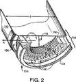
図1は、本発明の好ましい実施形態に従う、加熱容器100の組立図である。加熱容器100は、加熱の間、内容物を保持するためのチャンバ110を備える。好ましい形態において、このチャンバは、アノード処理した(anodized)アルミニウムを含むが、このチャンバは、他の実施形態において、他の熱伝導性の材料または複合材料(例えば、ステンレス鋼または銅を含むものなど)から作製され得る。チャンバ110の面は、円筒形部材112から形成され、この部材は、閉じた底端部114から頂端部115まで延びる。蓋102は、頂端部115を覆ってぴったりと嵌り、チャンバ110を閉じる。蓋102は、例えば、熱可塑性材料から作製され得る。この実施形態において、必須ではないが、チャンバ110は、蓋102をはめた状態で、約1リットル程度の容積を有し、すなわち、一般に、ほんの2つの例としては、1人分の飲料または1缶のスープを保持および加熱するために十分である。チャンバ110の高さhは、約5.5インチ(図3を参照のこと)であり、そして内径dは、約4インチ未満(図2を参照のこと)である。
FIG. 1 is an assembly view of a
本発明に従って、ヒータ130は、高効率の熱交換器を備える。ヒータ130、またはその一部は、チャンバ110の底端部114の外面(図2の外側底面と称される)に、永続的にかまたは取り外し可能に結合され得る。代表的なキャンプ用ヒータまたはストーブヒータは、非常に良好な条件下で、約35〜45%の熱移動効率(すなわち、熱源(例えば、バーナー)によって排出される熱の、チャンバの内側に移動される量の百分率)を達成し得る。しかし、本発明の熱交換器によって達成される熱移動は、同じ条件下で、50%を超え、そして好ましくは、75%以上である。標準条件において、本発明に従う熱交換器の効率は、約90%より高い。
In accordance with the present invention,
好ましい実施形態において、ヒータ130は、頂部150および底部(または基部)140を備える。頂部150は、頂部ハウジング158を備え、これは、スカートの形態を採り得、このスカートは、チャンバ110の底端部114に結合されるように構成された頂部リム152、および底部140の頂部リム146に結合されるように構成された底部リム154を備え、この底部140は、基部の形態を採り得る。この実施形態において、頂部150および底部140は、不使用時に、チャンバ110内の底部140の格納を容易にするように、結合を外され得ることが好ましい(図4を参照のこと)。従って、頂部150と底部140との間の結合は、例えば、差し込み結合、スナップ結合、または螺合結合であり得る。頂部ハウジング158は、アノード処理されたアルミニウム材料から作製され得るが、熱伝導性が高い必要はない。
In a preferred embodiment, the
他の実施形態において、頂部150、またはその少なくともいくらかの構成要素は、底部140、またはその少なくともいくらかの構成要素と一体であり得る。例えば、頂部ハウジング158は、底部140と一体であり得る。他の形態において、突出物160が、チャンバ110の外部底面116と嵌合するように構成された、熱伝導性プレートに結合され得、これによってまた、スカート158と一体であり得るか、または外部底面116から少なくとも取り外し可能であり得る。
In other embodiments, the top 150, or at least some of its components, can be integral with the bottom 140, or at least some of its components. For example, the
底部140は、バーナーまたはバーナーヘッド(図3のバーナー302を参照のこと)の形態をとる、熱源を備える。このバーナーは、ヒータ130の燃料取り込みポート144に結合される燃料源104から、燃料を受容する。この実施形態において、燃料源104は、ガス源であり、例えば、混合されたプロパンおよびブタンの加圧キャニスターである。このような燃料源は、当該分野において、特に、キャンプおよびハイキングの分野において、公知である。他の実施形態において、燃料源は、異なる型のもの(例えば、白色ガス(white gas)、燈油、アルコール、またはガソリン)であり得る。なお他の実施形態において、燃料源は、電気または固形燃料を含み得る。
The bottom 140 comprises a heat source in the form of a burner or burner head (see
図1の実施形態において、燃料弁ノブ149は、使用者が、バーナーに供給される燃料を調節することを可能にし、そして点火ボタン148は、バーナーの点火を引き起こす内部点火器(図3を参照のこと)と連絡する。このバーナーは、火炎を生じ、そして維持するために、特定の量の酸素を必要等する。この火炎は、燃焼するにつれて、熱放出を生じる。従って、ヒータ130は、バーナーへの酸素の供給、およびバーナーからの排気ガスの流れを可能にするように構成された、ガス流路を備える。操作において、減圧が、ガス流路を通して形成され、これは、この結果を達成する。
In the embodiment of FIG. 1, the
ヒータの頂部150および底部140は、組み合わさって、ガス流路を形成する。底部140は、底部ハウジング147を備え、この底部ハウジングは、複数の空気入口ベント142を備え、これらのベントは、空気が、外部環境からバーナーに流れることを可能にする。この実施形態において、底部ハウジング147は、熱可塑性材料から作製され得、そしてまた、燃料源104が取り付けられていない場合に加熱容器100を支持する、脚部を形成する。頂部部分150の頂部ハウジング158は、一連の排気ベント156を備え、これらの排気ベントは、バーナーから外部環境(すなわち、ヒータの外側)への排気通路を提供するように構成される。ガス流路のさらなる詳細は、図3に関する議論から明らかになり得る。
The
図2は、チャンバ110およびヒータ130の頂部150の切り取り斜視図を提供する。見られ得るように、頂部ハウジング158は、ほぼ円筒形であり、そして熱伝導性の半径方向に配置された一連のフィン160(ここでは、リングの形態で示されている)を囲む。好ましい形態において、フィン160は、アノード処理されたアルミニウムから作製されるが、他の熱伝導性材料(例えば、銅または鋼鉄)が使用され得る。図2のフィンは、円形のフィン配置に形成された、材料の単一ストリップから作製されるが、これらが材料の単一片から構成されることは、必須ではない。フィン160は、チャンバ底端部114の外側底面116に結合される。図2の実施形態において、これらのフィンは、外部底面116に鑞付けされるが、はんだ付けされても、接着されても、または電気的に溶接されても超音波溶接されてもよい。底端部114の反対側は、チャンバ110の内部の一部を収容する、内部底面(見えない)である。
FIG. 2 provides a cut-away perspective view of the
外側底面116の中心領域118は、フィン160によって囲まれている。中心領域118は、バーナーからの熱のかなりの部分を受容する。熱の残りの大部分は、例えば、矢印Aによって示されるように、バーナーからフィンを通って、ベント156を介して頂部ハウジング158へと出る、熱排気ガスとして、フィン160によって受容される。
A
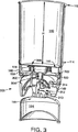
図3は、図1のヒータ130を示す切取図である。頂部ハウジング158は、チャンバ110に結合され、そしてフィン160を囲んで示されており、これらのフィンは、チャンバ110の底端部114の外部底面116に結合されている。示されるように、フィン160は、チャンバ底端部114の外部底面116から高さHだけ延び、この高さは、この実施形態において、約1/2インチである。
FIG. 3 is a cutaway view showing the
ヒータ130の底部140は、燃料弁アセンブリ300に結合されたバーナー(またはバーナーヘッド)302を備える。燃料弁アセンブリ300は、燃料/空気混合管304を備え、この管は、燃料弁本体310から延びる。燃料弁本体310の内部に、弁棒312が配置され、この弁棒は、弁棒ノブ149(図1もまた参照のこと)を備える。弁棒312および弁棒ノブ149は、一緒になって、使用者が、燃料源104(これは、燃料取り込みポート144に結合された)からの燃料の流れを制御することを可能にする。燃料は、燃料タンク104から圧力解放され、燃料弁本体310を通り、そして弁棒312を通って、開口部314に入り、次いで、燃料/空気混合管304に入る。当該分野において公知であるように、燃料/空気混合管304は、開口部を備え、この開口部は、周囲の空気が、管内に圧力解放される燃料と混合することを可能にする。周囲の空気は、ガス流路を介して受容され、そして底部140に形成された空気入口ベント142から引き込まれる。点火器306は、バーナー302に火花を提供し、これにより、バーナーでの燃焼が引き起こされる。点火器306は、使用者が点火ボタン148(図1に示される)を作動させることに応答して、火花を発生させる。
The
好ましい実施形態において、ディスク形状の基部プレート320が、バーナー302の下方に配置され、点火器306が、基部プレート320を通過し、その結果、この点火器は、バーナー302に火花を提供し得る。ヒータ底部140が頂部150に結合された状態で、バーナー302およびフィン160は、チャンバ110の基部プレート320、頂部ハウジング158および外部底面116によって形成される空洞内に収容される。基部プレート320におけるベント322は、さらなる酸素(または燃焼を完了させるために必要とされる二次的燃焼空気)のガス流路が、ヒータ130の底部ハウジング140内のベント142からヒータの頂部ハウジング158内のベント156を通して維持されることを可能にする。必要に応じて、底部140のベント142および基部プレート320のベント322は、バーナー302の所望の最大燃焼速度を達成するように選択される。好ましい形態において、バーナー排出は、約7,000BTUHであるように選択されるが、他のバーナーにより望まれる最大排出が選択され得、そしてそれに従ってベントの大きさが決められ得る。対応する燃焼速度について、基部プレート320における全空気ベント面積は、約1.38平方インチである。より高い燃焼速度が容易に達成される一方で、食品の準備においては、より高い燃焼速度は、食品を焦がし得る。好ましくは、所望の最大燃焼速度にかかわらず、ベントは、燃料の最も効率的な燃焼および可能な限り高い熱移動を確実にするように、選択される。基部プレート320における過剰の空気ベントの総面積は、過剰の空気を導入し、バーナー排気の温度を下げ、従って、加熱効率を下げる。不十分な空気ベント面積は、バーナーへの必要な二次燃焼空気を制限し、不完全燃焼を生じる。一例として、本明細書中に記載されるパラメータを使用すると、加熱容器100は、約2分間で、1リットルの水を沸騰させ得る。
In a preferred embodiment, a disk-shaped
また、組み立てられた形態で、バーナー302は、フィン160のリングの内周内に配置される。この実施形態において、バーナーは、約1と3/8インチの直径を有し、フィンの内径は、約1と7/8インチであり、そしてフィンの外径は、約3と5/16インチであり、フィンの高さHは、約1/2インチである。この実施形態において、フィン160の内径は、バーナー302および点火器306を囲むために十分に大きくされる。バーナー302はまた、チャンバ110の底端部114の外側底面116から約H未満の距離に固定される。この構成において、バーナー302によって発生される火炎は、フィン160によって囲まれる。この構成から、高い熱移動が達成され、ここで、バーナー302によって提供される熱の大部分は、加熱チャンバの外側底面116の中心領域118およびフィン160に移動され、排気ガスは、フィン160を通って、およびフィン160の周りを通過する。
Also, in an assembled form, the
図4は、燃料源104に結合され、そしてチャンバ110内に嵌められた、ヒータ130の底部140の図を示す。これらの要素を入れ子状にする能力は、必須ではないが、格納および移動のための加熱容器100の簡潔な包装を提供する。蓋102は、点火器306およびバーナー302を受けるための突出物400を備え得る。蓋はまた、ベント穴404を備え、チャンバ110内に蓄積された圧力に対する解放弁として働き得る。蓋102はまた、丸い開口部406(図面では見えない)を備え、チャンバ110からの飲料の引用に適応され得る。他の実施形態において、突出物402によって形成されたカップは、計量マークを備え得る(例えば、小さじ、大さじなど)。他の実施形態において、この蓋は、外側の、垂直方向に配置されるリッジまたは突出物を備えて、使用者に対するより良好な把持を提供し得る。
FIG. 4 shows a view of the bottom 140 of the
好ましい形態において、熱交換器の効率に大きく起因して、熱の大部分は、排気ベント156に逃れる代わりに、チャンバ110の内部に移動され、そして図5に示されるように、さらなる低温サービス範囲のさらなる快適さのために、チャンバスライド112およびヒータ頂部150のかなりの部分を覆って嵌められる、断熱材500が提供され得る。あるいは、プラスチックまたは金属のハンドルが、チャンバ側面112に取り付けられるように使用され得る。第一のセクション510は、チャンバ110の側面112を囲む。第二のセクション520は、ヒータ130の頂部150を囲む。第二のセクション520の損失を回避するために、第二のセクションは、好ましくは、第一のセクション510に結合される。この実施形態において、第一のセクション510および第二のセクション520は、ネオプレンから作製されるが、他の断熱材料(例えば、ゴム)が使用され得る。断熱材500は、ハンドル530を備え、このハンドルは、第一のセクション510を第二のセクション520に結合するヒンジとして働く。あるいは、ハンドル530は、加熱容器100を保持および運ぶために有用である。良好な閉鎖を確実にするために、第一のセクション510および第二のセクション520の両方が使用されている場合に、これらのセクションをしっかりと接合する、ジッパー532(例えば、マイクロジッパー)が、備えられ得る。「D」リング534もまた加熱容器100の容易なクリップ止めを可能にするために、備えられ得る。
In the preferred form, largely due to the efficiency of the heat exchanger, most of the heat is transferred to the interior of the
図6Aおよび6Bは、本発明に従う加熱容器600の別の実施形態を示す。図6Aは、完全に組み立てられた図であり、ここで、加熱容器は、燃料源(例えば、図1にもまた示される燃料源104)から燃料を得るように構成されている。チャンバ610は、加熱されるべき内容物を保持するように構成され、そして蓋602を受容するように構成された頂端部を備える。チャンバ610は、二重壁チャンバであり、外側壁612および内側壁614を備える(図6Bもまた参照のこと)。図1の加熱容器100は、単一壁チャンバ110を備えて示されたが、これはまた、二重壁の設計を利用し得る。外側壁612の外部表面には、断熱把持層604が配置される。断熱把持層604は、このユニットを把持する際の改善された安全および把持領域の温度の低下を提供する。一例として、断熱把持層604は、ゴム、ネオプレンまたは任意の多数の他の市販の断熱材料から作製され得る。
6A and 6B show another embodiment of a
この実施形態において、ヒータ630は、チャンバ610と一体である。ヒータ630は、基部ハウジング644を備える。基部ハウジング644は、一連の脚部(または支持体)646を備え、これらは、燃料源104が外された場合に、加熱容器600を支持する。ガス流路が、一連の複数の空気入口ベント642(図6Bを参照のこと)(基部ハウジング644内に位置する穴またはギャップとして形成される)と、一連の排気ベント656(チャンバ610の外側壁612の上部に形成される)の間に確立される。一次空気入口ベント642は、内部バーナーへの空気の一次供給源として働き(図6Bを参照のこと)、一方で、一連の二次空気入口ベント643もまた、バーナーへの空気供給を補助するために、提供され得る。
In this embodiment, the
図6Bは、図6Aの加熱容器600の断面切り取り図を示す。ヒータ630は、燃料源104に結合されるように構成された、燃料取り込みポート606を備える。バーナー632は、燃料源104の上方でありかつ一連の突出物の内部に配置され、燃料弁アセンブリ666が、これらの間に配置される。燃料弁アセンブリ666は、ヒータ630の一部を形成し、そして基部ハウジング644に収容される。燃料弁アセンブリ666は、図3の燃料弁アセンブリと実質的に同じであり、従って、加熱容器600に関しては詳細には記載しない。
FIG. 6B shows a cutaway view of the
ガス流路を達成するために、ガスは、矢印Bによって示されるように、空気入口ベント642、643からバーナー632へと移動し、そしてバーナー632から、燃焼排気が、突出物660の周りを移動し、そして外側壁612と内側壁614との間を上がり、次いで、排気ベント656から出る。一次空気入口ベント642は、基部プレート650の下方の堆積内(すなわち、バーナー632に供給する燃料/空気混合管646を備える領域)への一次燃焼空気の進入を可能にするように機能する。基部プレート650は、外側壁612の底部かつ内側、かつバーナー632および二次空気入口ベント643の下方に位置する。この構成は、二次空気入口ベント643からの空気が、バーナー632に直接行くことを可能にするように構成される。基部プレート650は、バーナー632およびバーナー点火器636のための切り込みを備え、基部プレートを通って上方に突出する。
To achieve the gas flow path, gas travels from the air inlet vents 642, 643 to the
基部プレート650は、バーナー632から発する熱い燃焼副生成物が、バーナー燃料−空気混合物(これは、発生されて、ヒータ基部のハウジング644および基部プレート650の内部に規定された、下部の空間内のバーナーに供給される)と混合し、そして/またはこの混合物を妨害することを防止する、障壁を提供する。従って、基部プレート650は、バーナー632の信頼性のある点火および全体の性能を提供する。二次空気入口ベント643は、より大きい空気の流れが、十分な燃焼のためにバーナー632において必要とされる場合には、任意である。他の実施形態において、ヒータ630、ハウジング644、またはこれらの種々の構成要素は、チャンバ610から取り外し可能であり得る。例えば、ヒータ630またはハウジング644は、任意の数の手段(例えば、先に議論されたもの)によって、取り付けられ得る。
The
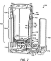
図7は、加熱容器700の別の実施形態の断面図であり、これは、一体的ユニットに形成されたチャンバ702およびヒータ704を使用し、遠隔位置で液体食料品を加熱するための、小型の、容易に持ち運び可能なデバイスを提供する。このような液体食料品としては、加熱料理用の熱湯、茶、コーヒー、ブロス、および一般に液体の濃度(液体食料品を通しての対流による熱移動を可能にする)を有する他の食料品(例えば、スープおよびシチュー)が挙げられる。
FIG. 7 is a cross-sectional view of another embodiment of a
ヒータ704は、燃料供給システム706を結合し、このシステムは、ガス燃料(例えば、加圧下のブタンまたはプロパン)を収容するための交換可能な燃料タンク708、内部に交換可能な燃料タンク708が受容され得る燃料タンク受容器710、ならびに燃料タンク受容器710に受容される場合に交換可能な燃料タンク708と連絡する、燃料供給および混合ライン712を有する。図示される実施形態において、燃料タンク受容器710は、チャンバ702からずらし、そしてチャンバ702と並べて燃料タンク708を配置するように構成され、その結果、燃料タンク708は、使用者のための、加熱容器700のハンドルとして働き得る。
The
ヒータ704は、周囲境界718によって境界を定められる上部支持構造体714およびバーナーヘッド716を有する。図示されるバーナーヘッド716は、オープンフレーム型であるが、放射型バーナーヘッドが使用され得ることが、理解されるべきである。燃料供給および混合ライン712は、バーナーヘッド716と連絡し、そしてガス燃料および一次燃焼空気を、バーナーヘッド716に提供する。燃料供給および混合ライン712は、燃料−空気混合管720を備え、この管の中で、ガス燃料のストリームが、一次燃焼のための空気を巻き込み、その後、バーナーヘッド716に達する。加熱容器700の全体の高さを最小にするために、燃料−空気混合管720は、その長さのかなりの部分にわたって水平である。この実施形態の上部支持構造体714は、多数の空気取り込みベント722を有し、これらは、周囲の空気の進入を可能にし、空気を燃料−空気混合管720内への導入のために利用可能にし、そして二次燃焼のための空気が、使用される特定のバーナーヘッド716によって要求される場合には、このような二次燃焼のための空気を提供する。取り込みベント722はまた、使用者が、マッチまたは他の点かデバイスを挿入してバーナーヘッド716に点火することを可能にするために、十分に大きい大きさにされ得る。
The
チャンバ702は、内側容器724を有し、この内側容器は、内側容器内部表面726および内側容器外部表面726を有する。内側容器724は、開口頂部730で終結し、そしてそこから下方へ、内側容器底部732まで延びる。内側容器724は、加熱されるべき液体を保持するための構造体を提供する。内側容器724は、伝導性が高い材料(例えば、アルミニウム)から形成され、そして内側容器の内部表面726は、好ましくは、洗浄の場合に比較的不活性な、非粘着性の表面を提供する傾向がある。このような表面は、アノード処理、Teflon(登録商標)などのコーティングの塗布、または当該分野において公知の類似の技術によって、形成され得る。内側容器724は、好ましくは、図示されるように、下部円筒形セクション734および上部切頭円錐セクション736を備え、これは、開口頂部730において終結する。
チャンバ702はまた、ハウジング738を備え、このハウジング内に、内側容器724が存在する。ハウジング738は、ハウジング側壁740を有し、このハウジング側壁は、ハウジング側壁外部表面742およびハウジング側壁内部表面74を備える。ハウジング側壁740は、任意の適切な耐熱材料から形成され得、1つの好ましい材料は、外観を魅力的にし、そして洗浄が容易な、ステンレス鋼である。ハウジング側壁740は、内側容器724に対して構成され、それによって、内側容器外側表面728とハウジング側壁内部表面744との間環状ギャップ746を提供する。ハウジング側壁740は、ハウジング側壁基部領域748およびハウジング側壁頂部領域750において終結する。ハウジング側壁頂部領域750は、多数の排気ベント752を有し、これらのベントは、環状ギャップ746と連絡して、このベントからの空気および気体の出現を可能にする。底部円筒形セクション734および上部切頭円錐セクション736を有する内側容器724を形成することにより、環状ギャップ746の提供を容易にし、同時に、ハウジング738について比較的一定の直径を維持し、その外観を改善し、そして吹き上がった液体が排気ベント752に入る可能性を最小にし、同時にまた、開口頂部730を比較的広く維持し、内側容器724へのアクセスを容易にする。
内側容器724は、ハウジング738内に配置され、そしてこの実施形態において、リム片754によって内部に固定される。このリム片は、内側容器724の開口頂部730と、ハウジング側壁頂部領域750との両方に付着する。リム片754は、好ましくは、低い熱伝導性を有する材料(例えば、耐熱プラスチック)から形成され、使用者が、内側容器724から、火傷の危険性なく液体を快適に吸うことを可能にする。
ハウジング738をヒータ704の上部支持構造体714に設置するための手段もまた提供される。この実施形態において、これらの手段は、側壁基部領域748を、上方支持構造体714と一体的に形成することによって、提供される。ヒータ704およびハウジング側壁740は、バーナーヘッド716が内側容器底部732の下方に配置され、そして好ましくは、内側容器底部に対して中心を合わせられるように構成される。従って、バーナーヘッド716が点火される場合、燃焼している燃料は、内側容器底部732を加熱する。内側容器724は、熱伝導性の高い材料から形成されるので、内側容器底部732は、熱を、液体を加熱するための内側容器724内に収容される液体に伝導する。バーナーヘッド716が作動する場合、このバーナーヘッドは、燃焼ガスを発生し、このガスは、環状ギャップ746内に通り、そして最終的に、排気ベント752を通って出、一方で、燃焼のための周囲の空気が、取り込みベント722を通って入る。
Means are also provided for installing the housing 738 on the
下向きに方向付けられた突出物756のアレイが、内側容器内部表面728に取り付けられる。これらの突出物756は、熱伝導性の高い材料(例えば、アルミニウムまたは銅)から形成される。突出物756は、内側容器底部732を越えて延び、そしてバーナーヘッド716の周囲境界718の周りに配置され、これによって、バーナーヘッド716の周囲境界718を囲む空洞758を規定する。空洞758の境界は、突出物756によって形成され、これらの突出物は、連続表面によってではなく、不連続な要素であることが注目されるべきである。従って、突出物756は、熱いガスが突出物756の間を通って環状ギャップ746へと入るにつれて、バーナーヘッド716によるガスの燃焼によって発生される熱の大部分を、燃焼ガスから取り出すように配置される。同様に、バーナーヘッド716が放射バーナーである場合、突出物756は、バーナーヘッド716から放出された任意の放射熱、およびバーナーヘッド716を囲む加熱された空気からの熱を集め、その後、この加熱された空気が、環状ギャップ746に入る。いずれの場合においても、突出物756によって収集される熱は、内側容器724およびそこに収容される液体に移動され、加熱容器700の燃焼効率を大いに増加させる。突出物756のさらなる利点は、増加した熱交換が、環状ギャップ746に入るガスの温度を低下させ、ハウジング側壁740に伝導される熱の量を減少させ、そしてハウジング側壁外部表面742を快適な温度に維持することを補助することである。
An array of downwardly oriented
この実施形態の突出物756は、構成が矩形であり、そして好ましくは、少なくとも約5、より好ましくは約10と20との間のアスペクト比(突出物756の有効直径で除算された、突出物756の高さとして定義される)を有する。好ましい範囲の下限は、突出物756が、有意な程度の熱移動を提供することを仮定する。上限は、突出物756の製造を過度に複雑にすることなく、突出物756になおより大きい熱移動を提供することを仮定することを補助し、そして野外での加熱容器700の使用に耐えられるために十分な構造的一体性を有することを仮定することを補助する。さらに、特定の製造方法は、突出物756のアスペクト比の上限を、容易に製造され得るように制限し得る。突出物756が、矩形の断面を有する場合、そのアスペクト比は、その突出物の有効高さ(すなわち、内側容器底部732を超えて延びる突出物756の距離)対有効直径(これは、突出物756の矩形の断面と同じ面積を有する円の直径である)の比として定義される。
The
図示される突出物756は、矩形のフィンとして形成され、そして第一のリングのフィン760および第二のリングのフィン762として配置される。第一のリングのフィン760および第二のリングのフィン762は、シートストックから切り出されて、それらの矩形の断面を提供する。この場合、突出物756の有効直径は、この矩形断面と同じ面積を有する円の直径である。あるいは、突出物756は、正方形、円形、または他の形状の断面を有し得る。
The illustrated
第一の(内側の)リングのフィン760は、内側容器底部732に配置され、これによって、空洞758を形成する。第一のリングのフィン760は、ディスク764の周囲に容易に形成され得る。第一のリングのフィン760およびディスク764は、一体的な片としてシートストックから切り出され得、そして第一のリングのリン760は、その後、ディスク764に対して垂直に曲げられる。次いで、ディスク764は、鑞付け、はんだ付け、高温接着剤での接着、または類似の技術によって、内側容器底部732に固定され得る。しかし、ディスク764を内側容器底部732に固定するための技術は、第一のリングのフィン760からディスク764を介しての内側容器底部732への熱の移動を妨害するべきではない。第一のリングのフィン760のフィンは、好ましくは、シートストックの厚さよりかなり広い幅で切り出され、矩形の断面を提供し、そしてこれらのフィンの各々は、切断縁部の1つが半径方向内側に面し、その結果、これらのフィンが実質的に半径方向の配向になり、矩形断面の長い方の片が、実質的に半径方向に延びるように、曲げられる。第一のリングのフィン760のこの配向は、バーナーヘッド716から外向きの熱いガスの流れの、半径方向での妨害を実質的に最小にする。
A first (inner)
第二(外側)のリングのフィン762は、内側容器の外部表面728に取り付けられ、そして内側容器底部732を越えて下方に延びる。第二のリングのフィン762は、ストリップ766の1つの縁部に容易に形成され得、第二のリングのフィン762およびストリップ766は、シートストックから、一体的な片として切り出される。ストリップ766は、内側容器の外部表面728に取り付けられ得、そして第二のリングのフィン762は、その後、実質的に半径方向の配向になるように曲げられる。ストリップ766は、ディスク764を内側容器底部732に取り付けることに関して上で議論された、任意の技術によって、内側容器の外部表面728に取り付けられ得る。第二のリングのフィン762は、内側容器の外部表面728の一部を横断し得るが、第二のリングのリン762が内側容器の外部表面728に沿って遠すぎて延びる場合、効率が低下することが見出された。好ましくは、第二のリングのフィン762は、内側容器の高さHの1/4より大きくは内側容器の外部表面728を越えて延びない。内側容器の高さHは、内側容器底部732からの開口頂部730を分離する距離として定義される。ここでまた、第二のリングのフィン762のフィンは、好ましくは、シートストックの厚さよりかなり広く切り出され、そして切断縁部の1つが半径方向内側に面し、その結果、フィンが実質的に半径方向の配向になるように、各々が曲げられる。
A second (outer)
突出物756の製造方法は、シートストックの片の縁部から突出物を切り出す工程を包含し得、これは、突出物756に、比較的大きいアスペクト比を容易に提供することを可能にする。しかし、この技術は、チャンバ702を製造するために形成され、そして組み立てられなければならない個々の部品の数を増加させる。
The method of manufacturing the
突出物756は、内側容器724への熱の移動を大いに増加させるが、絶縁層768はまた、なおさらに加熱容器700の効率を改善するために、ハウジング側壁内部表面744に提供され得る。断熱材層768は、排気ベント752の下方の環状ギャップ746の一部に存在し、これによって、加熱された気体が環状ギャップ746を通り、そして排気ベント752を出ることを可能にする。断熱材層768のための1つの好ましい断熱材料は、セラミック紙(例えば、例えば、Lydall 1535 LKであり、これは、50%のアルミナ繊維および50%のシリカ繊維から構成され、そしてLydall,Inc.から入手可能である)である。断熱材層768は、内側容器724からの熱損失を低下させ、そしてハウジング側壁外部表面742を、快適な温度に維持することを補助する。
Although the
図8A〜8Cは、図示されるガスストーブ802のような従来のキャンプ用ストーブと共に使用するために設計された、加熱容器800を示す。従来の軽量ガスストーブ(例えば、図示されるガスストーブ802)は、周知であり、そして遠隔位置で食品を加熱するために、キャンプ、ハイキング、および類似の活動において使用されている。加熱容器800は、上記加熱容器700と比較して、低下した燃料効率を有し得るが、専用のヒータの代わりにガスストーブ802を使用する能力は、加熱容器800を使用し、かつ従来の食料品を使用する状況において、使用者によって運ばれる設備の全体的な量を、減少させ得る。
8A-8C illustrate a
ガスストーブ802は、周囲境界812によって境界を定められた、交換可能な燃料タンク806、燃料供給および混合要素808、ならびにバーナーヘッド810を有する、燃料供給システム804を有する。ガスストーブ802のバーナーヘッド810は、オープンフレームバーナーである。なぜなら、キャンプ用ストーブは、頻繁に、反射性の食品と共に使用され、放射型バーナーヘッドの使用を非実用的にするからである。しかし、加熱容器800は、放射型バーナーと共に効果的に使用され得ることが、理解されるべきである。従来の加熱調理容器(例えば、シチューなべまたはフライパン)を支持するために、ガスストーブ802は、4つの支持部材816を有する上部支持構造体814を有し、これらの部材の上に、加熱調理容器が載り得る。
The
加熱容器800は、内側容器818を有するチャンバ819を備え、この内側容器は、内側容器内部表面820および内側容器外部表面822を有する。内側容器818は、開口頂部824および内側容器底部826において終結し、これらは、内側容器高さHによって分離されている。内側容器818は、本質的に、上記内側容器724に類似する。
The
チャンバ819はまた、ハウジング828を有し、このハウジングの中に、内側容器818が入る。ハウジング828は、上記ハウジング728との多くの共通する特徴を有し、そしてハウジング側壁外部表面832およびハウジング側壁内部表面834を有する、ハウジング側壁830を有する。ハウジング側壁830は、内側容器外部表面822とハウジング側壁内部表面834との間に、環状ギャップ836を提供するように構成される。ハウジング側壁830はまた、ハウジング側壁基部領域838およびハウジング側壁頂部領域840において終結し、このハウジング側壁頂部領域は、環状ギャップ836と連絡する、多数の排気ベント842を有する。リム片844が提供され、これは、内側容器818の開口頂部824とハウジング側壁頂部領域840との両方に付着し、内側容器818をハウジング828内に固定する。断熱材層846が、好ましくは、ハウジング側壁内部表面834に提供される。
The chamber 819 also has a
ハウジング828をガスストーブ802の上部支持構造体814に設置するための手段が提供される。この実施形態において、側壁基部領域838は、上部支持構造体814の4つの支持部材816を、係合させて、その上のチャンバ819を支持し、従って、ハウジングを支持するための手段として働く大きさおよび形状にされた、多数の凹部848を備える。ガスストーブ802およびハウジング側壁830は、バーナーヘッド810が内側容器底部826の下方に配置され、そして好ましくは、その下で中心を合わせられるように、構成される。ガスストーブ802が作動する場合、燃焼のための空気が、バーナーヘッド810の周囲境界802の周りの側壁基部領域838に入る。
Means are provided for installing the
図示されるガスストーブ802は、90°の角度で配置される4つの支持部材816を有するが、多くのキャンプ用ストーブは、120°の角度で配置された、3つのみの支持部材を有する。加熱容器800が3支持体ストーブまたは4支持体ストーブのいずれでも使用されるようにするために、側壁基部領域838は、図8Bおよび8Cに示されるように、4つの支持部材を係合するために90°の角度で間隔を空けた第一の一連の凹部848’、および3つの支持部材を係合するために120°の角度で間隔を空けた第二の一連の凹部848”を備え得る。
The illustrated
凹部848は、1つの凹部848が第一の一連の凹部848’および第二の一連の凹部848”の両方において使用されるように間隔を空けられ得るが、この実施形態において、2つの一連の凹部(848’、848”)が分離され、これらは、上部支持構造体814を係合して希釈空気の進入を制限しない凹部(848’または848”)をブロックすることを可能にする。これは、側壁基部領域838にスライド可能に回転可能に係合するブロッキングリング850を使用することによって、達成され得る。ブロッキングリング850は、側壁基部領域838にきつく嵌まり、摩擦によってそこに維持されるような大きさにされ得る。あるいは、さらなる固定付着が望ましい場合、環状保持縁部(図示せず)は、側壁基部領域838上に提供され得、この上に、ブロッキングリング850が嵌められる。
The
図8Bおよび8Cに最良に示されるように、ブロッキングリング850は、第一の一連のカットアウト852’および第二の一連のカットアウト852”を有する。第一の一連のカットアウト852’は、第一の一連の凹部848’に適合するように、90°の角度で配置され、一方で、第二の一連のカットアウト852”は、第二の一連の凹部848”に適合するように、120°の角度で配置される。ブロッキングリング850は、側壁基部領域838に対してスライドし得、図8Bに示されるように、第一の一連のカットアウト852’を第一の一連の凹部848’と整列させるか、または3支持体キャンプ用ストーブが使用される場合、図8Cに示されるように、第二の一連のカットアウト852”を第二の一連の凹部848”と整列させる。一連のカットアウト(852’または852”)と整列しない一連の凹部(848’または848”)は、ブロッキングリング850によってブロックされて、そこを通って希釈空気が侵入することを防止する。
As best shown in FIGS. 8B and 8C, the blocking
図8Aを参照すると、チャンバ819は、そこに結合された、下向きに方向付けられた突出物854の配置を有し、これらの突出物は、内側容器外部表面822に取り付けられる。突出物854は、内側容器の外部表面822に取り付けられたリングのフォイン856に形成され、そして内側容器の底部826を越えて延びる。突出物854は、図7に示され、そして上で議論される、第二のリングのフィン762と類似の様式で形成され得る。突出物854は、バーナーヘッド810の周囲境界812の周りに配置され、これによって、周囲境界812の突出物を囲む空洞858を規定する。
Referring to FIG. 8A, chamber 819 has an arrangement of downwardly oriented
ガスストーブ802は、従来の加熱調理容器(これは、代表的に、チャンバ819より直径が大きい)と共に使用されることが意図されるので、ガスストーブ802のバーナーヘッド810は、図7に示される実施形態において使用されるバーナーヘッド116の周囲境界118よりかなり大きい周囲境界812を有する。このような場合において、補助的な突出物860の配置を使用して、バーナーヘッド810によって発生される加熱されたガスを内側容器818へと移動させる際に補助することが、有利であり得る。補助突出物860は、空洞858内に延び、そして図示される実施形態において、図7に示され、そして上で議論される第一のリングのフィン760と実質的に類似の様式で形成され得る。
Since the
加熱容器800は、好ましくは、ハウジング828に取り付けられるハンドル862を有する。ハンドル862は、永続的に取り付けられ得るが、ハンドル862は、取り外し可能であり、加熱容器800に、格納のためのより小型の全体の大きさを提供することが好ましい。好ましくは、ハンドル862は、格納のために取り外される場合に、内側容器818に収容されるように構成される。
The
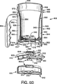
図9Aおよび9Bは、本発明の別の実施形態を示し、加熱容器900は、チャンバ919を備え、このチャンバは、専用のヒータ902とともに使用されるために設計され、小型の、容易に持ち運び可能な加熱デバイスを提供するが、チャンバ919およびヒータ902が、一体的なユニットを作製しない。このことは、チャンバ919が、洗浄が容易になるようにヒータ902から取り外されることを可能にし、押して引き続く、複数のチャンバの、単一のヒータ902での使用を可能にする。加熱容器900はまた、以下でさらに詳細に議論されるように、能動的な空気フローを使用して、加熱容器900の外側を断熱する。チャンバ919およびヒータ902の特定の詳細は、図9Bの断面図に最もよく示されている。
FIGS. 9A and 9B illustrate another embodiment of the present invention, wherein the
ヒータ902は、取り外し可能な燃料タンク906を使用する燃料供給システム904を有する。図9に示されるように燃料タンク継手908は、交換可能な燃料タンク906と燃料調節および混合アセンブリ910との間を連絡させる。燃料タンク継手(または燃料取り込みポート)908は、好ましくは、キャンプ用ガスストーブにおいて使用される、従来の燃料タンク継手と類似であり、標準的な燃料キャニスターが、燃料タンク906として使用されることを可能にする。このような従来の燃料キャニスターの1つの例が、図8において、ガスストーブ802の燃料タンク806として示されている。標準的な燃料キャニスターが使用され得るが、専用の燃料タンクが提供されて、燃料タンク906として働き得、燃料タンク906が、減少した高さを有し、より大きい燃料供給が必要とされない状況において、より軽い重量、より小型のヒータ902を提供することを可能にする。専用の燃料タンク906は、当該分野において公知の様式で再充填され得る。実用的な量の燃料を燃料タンク906内に保持するために必要とされる高圧に適合することを補助するために、図示される燃料タンク906は、そこに形成された多数の強化リッジ914を有する底部部材912を有し、従来の燃料キャニスターよりも大きい体積を、高さに対して有することを可能にする。
The
この実施形態の燃料混合および調節アセンブリ910は、ヒータ902が、従来のガスストーブを用いる場合より有意により小型になることを可能にする。燃料タンク継手908は、バーナーハウジング916の中心に位置し、その結果、燃料タンク906が燃料タンク906に取り付ける場合、バーナーハウジング916によって投影されるフットプリントは、燃料タンク906のフットプリントと実質的に同程度である。燃料混合および調節アセンブリ910は、燃料タンク継手908から燃料調節器920まで延びる燃料ライン918を有し、これは、そこを通り得る燃料の量を制御し得、そして燃料の供給を遮断するために閉じられ得る。使用者が燃料調節器920に容易にアクセスすることを可能にするために、燃料調節器は、好ましくは、バーナーハウジング916の周囲またはその近くに位置し、従って、燃料ライン918は、半径方向外向きに延びる。燃料調節器918から、燃料は、燃料−空気混合管922を通過し、この管の中で、ガス燃料のストリームが、一次燃焼のための空気を巻き込み、その後、バーナーヘッド924に達する。燃料−空気混合管922は、半径方向内向きに延びて、バーナーヘッド924を、バーナーハウジング916内で実質的に中心に配置する。ヒータ902に対する小型の構造を維持するために、燃料−空気混合管922は、その長さのかなりの部分にわたって、水平である。好ましい実施形態において、燃料混合および調節アセンブリ910は、燃料混合および調節アセンブリの頂部および燃料混合および調節アセンブリの底部を有する、クラムシェルアセンブリとして構成される。
The fuel mixing and
バーナーヘッド924における点火を容易にするために、点火器926が提供される。点火器926は、当該分野において周知であるような、バーナーヘッド924に供給される燃料/空気混合物に点火するための火花を提供するための、圧電点火器であり得る。好ましくは、点火器926は、燃料混合および調節アセンブリ910が作動されて燃料がバーナーヘッド924に供給される場合に、自動的に達成される。
An
バーナーハウジング916は、上部支持構造体928を有し、これは、この実施形態において、リングとして形成される。バーナーハウジング916はまた、多数の取り込みベント930を有し、これは、チャンバがヒータ902に取り付けられる場合に、バーナーハウジング916およびチャンバ919によって閉じ込められた領域への周囲の空気の進入を可能にする。
The
チャンバ919はまた、内側容器932を有し、この内側容器は、上に記載され、そして図7に示された内側容器724と実質的に類似である。内側容器932は、内側容器内部表面934、内側容器外部表面936を有し、そして開口頂部938および内側容器底部940において終結する。
The
チャンバ919はまた、ハウジング942を有し、このハウジング内に、内側容器932があり、ハウジング942は、ハウジング側壁944を有し、このハウジング側壁は、ハウジング側壁外部表面946およびハウジング側壁内部表面948を有する。ハウジング側壁944は、内側容器外部表面936とハウジング側壁内部表面948との間に、環状ギャップ950を提供するように構成される。ハウジング側壁944は、ハウジング側壁基部領域952およびハウジング側壁頂部領域954において終結する。ハウジング側壁頂部領域954は、それを通る多数の排気ベント956を有し、これらのベントは、環状ギャップ950と連絡する。リム片958が、内側容器932の開口頂部938およびハウジング側壁頂部領域954に付着して、内側容器932をハウジング942内で位置決めし、そして固定する。
The
この実施形態のハウジング側壁944は、ハウジング側壁944がハウジング側壁外部表面946とハウジング側壁内部表面948との間に環状通路960を有して形成されるという点で、先に議論された実施形態とは異なる。ハウジング側壁944は、外側壁部材962(ここに、ハウジング側壁外部表面946が部分的に提供される)および内側壁部材964(ここに、ハウジング側壁内部表面948が提供される)を有する。ハウジング側壁944は、ハウジング側壁基部領域952において、環状通路960内への空気の侵入を可能にし、そして環状ギャップ950と環状通路960との両方が、ハウジング側壁頂部領域954における排気ベント956と連絡することを可能にする。以下にさらに詳細に議論されるように、環状通路960を通る空気の流れを可能にすることによって、ハウジング側壁外部表面946を、快適な温度に維持することが補助される。
The
図示される実施形態において、上部ノッチ付きリング966および下部ノッチ付きリング968は、内側壁部材964を、外側壁部材962に対して位置決めするように働き、そしてハウジング側壁基部領域952内の環状通路960内への空気の流れ、および環状通路960からハウジング側壁頂部領域954における排気ベント956を通る空気の流れを可能にするように、構成される。好ましくは、上部ノッチ付きリング966および下部ノッチ付きリング968は、熱耐性材料(例えば、高温プラスチック)から形成されるが、内部壁部材964および外部壁部材962は、金属シートストックから形成される。
In the illustrated embodiment, upper notched
上部ノッチ付きリング966は、ハウジング側壁頂部領域954において、内部壁部材964と外部壁部材962との両方に付着する。上部ノッチ付きリング966は、上部リング連続領域970(これは、排気ベント956の上方にある)およびそこから下向きに延びる一連のリングポスト部材972(これは、排気ベント956を分離し、そして部分的に規定する)を有する。この実施形態において、外部壁部材962は、排気ベント956において終結し、そしてそれらの下縁部を規定し、一方で、上部リング連続領域970は、排気ベント956の上縁部を規定する。従って、ハウジング側壁外部表面946の一部は、上部ノッチ付きリング966によって形成され、そして好ましくは、リム片958は、上部リング連続領域970に取り付けられるか、またはこの領域と一体的に形成される。環状通路960内の空気は、上部リングポスト部材972の間の空間(これは、排気ベント956を形成する)を通って自由に流れる。内部壁部材946は、外部壁部材962の高さよりいくらか低く延び、従って、上部リング連続領域970の下方にあり、環状ギャップ950が排気ベント956と連絡することを可能にする。
The upper notched
下部ノッチ付きリング968は、下部リング連続領域974、およびそこから上向きに延びる一連の下部リングポスト部材976を有する。下部リング連続領域974は、外部壁部材962を密封して係合し、そして内部壁部材964の下で終結する。従って、下部リングポスト部材976は、環状通路取り込みポート978を分離し、そしてこのポートを部分的に規定し、これによって、空気が、内部壁部材964の下方の環状通路960に入ることを可能にする。下部リングポスト部材976は、環状通路取り込みポート978の垂直縁部を規定し、一方で、下部リング連続領域974および内部壁部材964は、環状通路取り込みポート978の水平縁部を規定する。あるいは、環状通路取り込みポート978は、外部壁部材962を通して提供され得、この場合、連続リングは、図示される下部ノッチ付きリング968を置き換え得る。
The lower notched
ヒータ902が作動する場合、環状ギャップ950内に通る加熱されたガスが、内部壁部材964を加熱する。内部壁部材964を通る熱の伝導は、環状通路960内にある空気のいくらかの加熱を引き起こす。この加熱された空気は上昇し、そして最終的に、排気ベント956を通って出、一方で、加熱されていない空気は、バーナーハウジング916およびチャンバ919によって囲まれる領域から引き出され、環状通路取り込みポート978を通る。環状通路960を通る空気の対流は、環状通路960内の熱の蓄積を防止し、そしてハウジング側壁外部表面946を、快適な温度で維持するように働き、使用者が、ヒータ902の作動の間に加熱容器900を取り扱うことを可能にする。
When the
ハウジング942をヒータ902の上部支持構造多928に設置するための手段が提供される。この実施形態において、これらの手段は、下部リング連続領域974によって提供され、これは、ヒータ902のリング形状の上部支持構造体928に取り外し可能に取り付けられるように設計される。下部リング連続領域974の、上部支持構造体928への取り付けは、ねじのねじ山、差込型設置具、周囲に配置されたクリップ、または当該分野において公知の類似の取り付け構造体によって、達成され得る。
Means are provided for installing the
下向きに方向付けられた突出物980の配置が、内側容器外部表面728に取り付けられ、そして図7に示される突出物980と類似であり、第一のリングのフィン982および第二のリングのフィン984内に配置される。ここでまた、第一のリングのフィン982は、バーナーヘッド924の周囲境界988を囲む空洞986を規定する。突出物980は、バーナーヘッドによって生じる加熱されたガスが突出物980を通って環状ギャップ950に入るにつれて、バーナーヘッド924によって生じる熱の大部分を集める。
The orientation of the downwardly oriented protrusions 980 is similar to the protrusions 980 attached to the inner container
バッフル(または基部)板990が、この実施形態において提供され、これは、内部壁964に取り付けられる。バッフル板990は、突出物980の下にあり、そして環状通路取り込みポート978の上方にある。バッフル板990は、プレート中心開口部992を備え、これは、この実施形態において、バーナーヘッド924の周囲境界988よりいくらか大きくされ、チャンバ919がヒータ902に設置される場合、バーナーヘッド924が、プレート中心開口部922を少なくとも部分的に通して挿入されることが可能である。プレート中心開口部992は、希釈空気が、バーナーヘッド924および突出物980がある領域に達することを制限する。バッフル板990は、好ましくは、金属シートストックから形成され、そして鑞付け、溶接、高温接着剤での接着、または類似の技術によって、内部壁部材964に固定され得る。あるいは、バッフル板990は、内部壁部材964と一体的な部分として形成され得る。
A baffle (or base)
この実施形態において、バッフル板990はまた、バーナーヘッド924によって発生された加熱された気体が、環状通路取り込みポート978を通って環状通路960に入ることを防止するために働く。バッフル板990は、突出物980の下方に位置するので、これはまた、突出物980を、チャンバ919がヒータ902から取り外される場合の損傷から保護するように働く。
In this embodiment,
環状通路960は、ハウジング側壁外部表面946が、不快に熱くなることを防止するが、加熱容器900は、好ましくは、使用者によるより容易な加熱容易900の把持のために、ハウジングに取り付けられたハンドル994を有する。ハンドル994は、好ましくは、取り外し可能であり、そして内側容器932内に格納されるように構成される。
Although the
図10は、上で議論された二重壁の実施形態のいずれかにおいて使用され得る、内側容器1000の部分を示し、これは、その上に設置される突出物1002の配置の細部が、上で議論された内側容器(724、818、932)とは異なる。内側容器1000は、内側容器底部1004を有し、ここに、突出物1002が固定される。好ましくは、内側容器1000は、ダイキャスティングによって形成され、突出物1002が、その内部に一体的に形成される。この理由により、突出物1002は、いくらかテーパ状であり、ある程度の隙間を提供し、内側容器1000および突出物1002をダイから取り外すことを容易にする。図示される突出物1002は、断面が円形であり、従って、突出物1002の有効直径は、断面の平均直径である。他の形状の突出物1002が、ダイキャスティングによって形成され得るが、突出物102のアスペクト比は、内側容器1000および突出物1002の、ダイからの取り外しを可能にするための必要性によって、制限され得る。
FIG. 10 shows a portion of the
突出物1002は、ダイキャスティングによって形成されるので、これらは、内側容器底部1004の任意の所望の配置で配置され得、図10に示される特定の配置は、ほんの一例である。この実施形態における突出物1002は、第一の(内側の)リングの突出物1006、第二の(中間の)リングの突出物1008、および第三の(外側の)リングの突出物1010に配置される。第一のリングの突出物1006の突出物1002は、内側容器底部1004上で中心を合わせられた空洞1012の境界を規定する。第二のリングの突出物1008の突出物1002は、第一のリングの突出物1006の突出物1002の間で、角度を付けて配置される。従って、空洞1012から半径方向外向きに流れる加熱されたガスは、最初に、第一のリングの突出物1006における突出物1002によって、個々のストリームに分離され、次いで、各ストリームが、第二のリングの突出物1008の突出物1002によって分離される。同様に、第三のリングの突出物1010の突出物1002は、第二のリングの突出物1008の突出物の間で、角度を付けて配置され、そして加熱されたガスのストリームが、再び第三のリングの突出物1010の突出物1020によって分離される。流れ込むガスを次第に小さくなるストリームに分離する作用は、突出部1002を、熱が最大であるストリームの中心に配置することによる熱移動を増強する。
Since the
図11は、突出物1100の別の構成を図示し、これは、図1に示されるような内部容器1102に対して、または図1に示されるようなチャンバに対して働き得る。突出物1100は、突出物片1106における波形1104によって形成される。波形1104は、空洞軸1110を有する空洞1108の周りに分布し、そして突出物1100のリング内に突出物片1106を形成し、これは、空洞軸1110に対して実質的に平行に延び、そして一連の接続セグメント1112が、隣接する突出物1100の間にある。突出物1100は、空洞軸1110に対して実質的に半径方向に配向される、フィンとして形成される。ここで、波形1104は、方形波の形状であり、そして接続セグメント1112は、空洞軸1110に対して実質的に垂直に延びる。このことは、代替の接続セグメント1112’が、内側容器1102(またはチャンバ)に対する取り付けのためのかなりの平坦な領域を提供することを可能にする。
FIG. 11 illustrates another configuration of
このような波形の突出物1106は、約0.012”の厚さTおよび約0.30”の幅Wを有する、アルミニウムストリップから形成され得る。この実施例における波形1104は、約0.55”の高さおよび約0.05”の突出物1100間の間隔Sを有する。幅W、厚さT、および高さHについてのこれらの値を使用すると、約8:1のアスペクト比を生じる。
Such
図12に示されるように、図11の突出物1100を有する内側容器1202は、ハウジング1214内に収容されて、環状ギャップ1218を有する二重壁のチャンバ1216を形成し得る。突出物1100が、そこを通過する熱い排気ガスから熱を取り出す際の効率に起因して、断熱材を、環状ギャップ1118に配置することが必要であることが見出された。断熱材を欠くこともまた、環状ギャップ1218を介してのフローを促進し得、さらに、ハウジング1214の温度を制限する。しかし、ハウジング1214を断熱することはまだ、加熱後に内部容器1202の内容物を冷却することを減少させる点で、非常に有利であり得る。
As shown in FIG. 12, the
上記は、最良の様式であるとみなされている実施形態および/または他の好ましい実施形態を記載したが、種々の改変がそこになされ得、そして本発明は、種々の形態および実施形態で実施され得、そして多数の適用において、適用可能であり得、これらのうちのほんの一部が、本明細書中に記載されたことが、理解される。本明細書中で使用される場合、用語「備える(includes)」および「備える(including)」は、限定なしであることを意味する。添付の特許請求の範囲によって、本発明の概念の範囲内に入る任意の全ての改変およびバリエーションが特許請求されることが、意図される。 While the above describes embodiments and / or other preferred embodiments that are considered to be the best mode, various modifications may be made therein and the invention may be practiced in various forms and embodiments. It will be appreciated that, and in a number of applications, it may be applicable, only a few of which are described herein. As used herein, the terms “includes” and “including” mean without limitation. It is intended by the appended claims to claim any and all modifications and variations that fall within the scope of the inventive concept.
Claims (36)
囲まれた面、熱伝導性底端部、および頂端部を有する容器であって、該頂端部は、加熱されるべき内容物の導入および取り出しのための開口部を形成し、該底端部は、熱を受容するための外部底面を有する、容器;
ヒータ
を備え、
該ヒータは、以下:
円周方向で該容器の該外部底面に結合されている頂部リム、該頂部リムから下向きに延び、そしてその中に形成されている複数の排気ベントを有する側面構造体、および底部リムを有する、頂部ハウジング;
単一の熱伝導性部材であって、該単一の熱伝導性部材は、連続片の材料を含み、該連続片の材料は、該外部底面の周辺端部の範囲全体に固定して取り付けられ、該外部底面の周辺端部の範囲全体に隣接して配置され、そして該外部底面の周辺端部の範囲全体に沿って連続的に延び、かつ、内径を規定する内部周辺端部および外径を規定する外部周辺端部を有し、該伝導性部材は、該外部底面から下向きに延びる複数の波状突出部を有する、単一の熱伝導性部材;
バーナーであって、該バーナーは、該外部底面の下に、該外部底面に対して中心の位置で配置される熱出口ヘッドを有し、そして燃料源に結合されるように構成された燃料取り込みポートを有し、該熱出口ヘッドは、該熱伝導性部材の内径よりも小さい直径を有し、そして該外部底面の中心領域に熱を送達するように構成されている、バーナー;
該底部リムと結合するように構成され、そして該熱源を実質的に囲む、底部ハウジングであって、該底部ハウジングは、その中に形成された複数の空気入口ベントを有する、底部ハウジング、
を備える、携帯型加熱システム。A portable heating system, which:
A container having an enclosed surface, a thermally conductive bottom end, and a top end, the top end forming an opening for introducing and removing contents to be heated, the bottom end A container having an outer bottom surface for receiving heat;
With a heater,
The heater is:
Top rim circumferentially coupled to the external bottom surface of the container, extending downwardly from said top rim and having a side structure Zotai, and bottom rim having a plurality of exhaust vents formed therein , Top housing;
A single thermally conductive member, the single thermally conductive member comprising a continuous piece of material, the continuous piece of material being fixedly attached to the entire area of the peripheral edge of the outer bottom surface An inner peripheral edge and an outer edge disposed adjacent to the entire peripheral edge region of the outer bottom surface and continuously extending along the entire peripheral edge region of the outer bottom surface and defining an inner diameter A single thermally conductive member having an outer peripheral edge defining a diameter, the conductive member having a plurality of undulating protrusions extending downwardly from the outer bottom surface;
A burner, wherein the burner has a heat outlet head disposed below the outer bottom surface at a central location relative to the outer bottom surface and configured to be coupled to a fuel source A burner having a port, the heat outlet head having a diameter smaller than the inner diameter of the thermally conductive member and configured to deliver heat to a central region of the outer bottom surface;
A bottom housing configured to couple with the bottom rim and substantially surrounding the heat source, the bottom housing having a plurality of air inlet vents formed therein;
A portable heating system comprising:
バーナーであって、該バーナーは、加熱されるべき表面の下の中心に配置される熱出口ヘッドを有し、そして燃料源に結合されるように構成された燃料取り込みポートを有し、該熱出口は、ほぼ丸い形態であり、一定の直径を有し、そして該表面の中心領域に熱を送達するように構成されている、バーナー;
単一の熱伝導性部材であって、該単一の熱伝導性部材は、連続片の材料を含み、該連続片の材料は、該表面の周辺端部の範囲全体に固定して取り付けられ、該外部底面の周辺端部の範囲全体に隣接して配置され、そして該外部底面の周辺端部の範囲全体に沿って連続的に延び、かつ、内径を規定する内部周辺端部および外径を規定する外部周辺端部を有し、該内径は、該一定の直径よりも大きく、該伝導性部材は、該表面から下向きに延びる複数の波状突出部を有する、単一の熱伝導性部材;
頂部リムを有するスカートであって、該頂部リムは、円周方向で、該表面に結合されており、そして該突出物を囲んでおり、該スカートは、その内部に形成された一連の排気ベントを有し、そして底部リムを有する、スカート;
該底部リムと結合するように構成され、そして該バーナーを実質的に囲む、基部であって、該基部は、その中に形成された一連の空気入口ベントを有する、基部
を備える、携帯型加熱システム。A portable heating system, the portable heating system:
A burner having a heat outlet head disposed centrally below the surface to be heated and having a fuel intake port configured to be coupled to a fuel source; The outlet is in a generally round form, has a constant diameter and is configured to deliver heat to a central region of the surface;
A single thermally conductive member, the single thermally conductive member comprising a continuous piece of material, the continuous piece of material being fixedly attached to the entire area of the peripheral edge of the surface. An inner peripheral edge and an outer diameter disposed adjacent to the entire peripheral edge range of the outer bottom surface and extending continuously along the entire peripheral edge range of the outer bottom surface and defining an inner diameter A single thermally conductive member having an outer peripheral edge defining the inner diameter, the inner diameter being greater than the constant diameter, and the conductive member having a plurality of undulating protrusions extending downwardly from the surface ;
A skirt having a top rim, the top rim being circumferentially coupled to the surface and surrounding the protrusion, the skirt being a series of exhaust vents formed therein And a skirt having a bottom rim;
A portable heating comprising a base configured to couple with the bottom rim and substantially surrounding the burner, the base having a series of air inlet vents formed therein system.
囲まれた面、熱伝導性底端部、および頂端部を有する容器であって、該頂端部は、該物質の導入および取り出しのための開口部を形成し、該底端部は、熱を受容するための中心領域を有する外部底面を有する、容器;
一連の一体化して接続された熱伝導性突出部であって、該突出部は、連続片の材料を含み、該連続片の材料は、該外部底面の周辺端部の範囲全体に固定して取り付けられ、該外部底面の周辺端部の範囲全体に隣接して配置され、そして該外部底面の周辺端部の範囲全体に沿って連続的に延び、該突出部は、該容器の外部底面から延び、そして該中心領域と一緒に一定の直径を有する空洞を規定する、突出部;ならびに
熱源を備えるヒータであって、該熱源は、該空洞の下に配置された熱出口ヘッダーを有し、そして該空洞へ熱を送達するように構成されており、該ヘッダーは、ほぼ丸の形状であり、そして該一定の直径よりも小さい直径を有する、ヒータ
を備える、システム。A system for heating a material, the system comprising:
A container having an enclosed surface, a thermally conductive bottom end, and a top end, the top end forming an opening for introduction and removal of the material, and the bottom end A container having an outer bottom surface with a central region for receiving;
A series of integrally connected thermal conductive protrusions, the protrusions comprising a continuous piece of material, the continuous piece of material being secured to the entire extent of the peripheral edge of the outer bottom surface. Attached, disposed adjacent to the entire peripheral edge region of the outer bottom surface, and continuously extending along the entire peripheral edge region of the outer bottom surface, the protrusion extending from the outer bottom surface of the container A heater that includes a protrusion that extends and defines a cavity having a constant diameter with the central region; and a heat source, the heat source having a heat outlet header disposed under the cavity; And a system configured to deliver heat to the cavity, the header comprising a heater having a generally round shape and having a diameter smaller than the constant diameter.
Applications Claiming Priority (4)
| Application Number | Priority Date | Filing Date | Title |
|---|---|---|---|
| US39148002P | 2002-06-25 | 2002-06-25 | |
| US42030502P | 2002-10-22 | 2002-10-22 | |
| US42980002P | 2002-11-27 | 2002-11-27 | |
| PCT/US2003/019957 WO2004000082A2 (en) | 2002-06-25 | 2003-06-25 | Heating vessel |
Related Child Applications (1)
| Application Number | Title | Priority Date | Filing Date |
|---|---|---|---|
| JP2009002034A Division JP5065308B2 (en) | 2002-06-25 | 2009-01-07 | Heating container |
Publications (3)
| Publication Number | Publication Date |
|---|---|
| JP2005530564A JP2005530564A (en) | 2005-10-13 |
| JP2005530564A5 JP2005530564A5 (en) | 2006-07-27 |
| JP4295724B2 true JP4295724B2 (en) | 2009-07-15 |
Family
ID=30003829
Family Applications (3)
| Application Number | Title | Priority Date | Filing Date |
|---|---|---|---|
| JP2004516214A Expired - Lifetime JP4295724B2 (en) | 2002-06-25 | 2003-06-25 | Heating container |
| JP2009002034A Expired - Lifetime JP5065308B2 (en) | 2002-06-25 | 2009-01-07 | Heating container |
| JP2012004986A Withdrawn JP2012106003A (en) | 2002-06-25 | 2012-01-13 | Heating container |
Family Applications After (2)
| Application Number | Title | Priority Date | Filing Date |
|---|---|---|---|
| JP2009002034A Expired - Lifetime JP5065308B2 (en) | 2002-06-25 | 2009-01-07 | Heating container |
| JP2012004986A Withdrawn JP2012106003A (en) | 2002-06-25 | 2012-01-13 | Heating container |
Country Status (8)
| Country | Link |
|---|---|
| US (1) | US20040011350A1 (en) |
| EP (1) | EP1521540B1 (en) |
| JP (3) | JP4295724B2 (en) |
| AT (1) | ATE410100T1 (en) |
| AU (1) | AU2003245665A1 (en) |
| DE (1) | DE60323978D1 (en) |
| DK (1) | DK1521540T3 (en) |
| WO (1) | WO2004000082A2 (en) |
Cited By (1)
| Publication number | Priority date | Publication date | Assignee | Title |
|---|---|---|---|---|
| KR101909334B1 (en) * | 2015-03-11 | 2018-12-10 | 정-옌 청 | Stockpot |
Families Citing this family (39)
| Publication number | Priority date | Publication date | Assignee | Title |
|---|---|---|---|---|
| US7205509B2 (en) * | 2004-04-26 | 2007-04-17 | Goulet N Kay | Heated food serving apparatus and method therefor |
| JP2008536265A (en) * | 2005-03-29 | 2008-09-04 | ザ・コールマン・カンパニー・インコーポレイテッド | Lantern with removable glove assembly |
| US7147634B2 (en) | 2005-05-12 | 2006-12-12 | Orion Industries, Ltd. | Electrosurgical electrode and method of manufacturing same |
| US8814861B2 (en) | 2005-05-12 | 2014-08-26 | Innovatech, Llc | Electrosurgical electrode and method of manufacturing same |
| US20070107715A1 (en) * | 2005-10-27 | 2007-05-17 | Daniel Grunberg | Apparatus and Method for a Self-Contained Heating Vessel |
| US20090090353A1 (en) * | 2005-10-27 | 2009-04-09 | Daniel Grunberg | Apparatus and Method for a Self-Contained Heating Vessel |
| US20080029082A1 (en) * | 2006-08-04 | 2008-02-07 | Dowst W Perry | Interchangeable system for high-efficiency heating and cooking |
| CN101611265B (en) * | 2006-11-10 | 2012-10-10 | 烧烤用具有限责任公司 | Radiant tube broiler |
| US20090092939A1 (en) * | 2007-10-03 | 2009-04-09 | Irwin Industrial Tool Company | Torch and canister |
| WO2010065155A1 (en) * | 2008-12-01 | 2010-06-10 | Best Willie H | Methods and apparatus for generating infrared radiation from convective products of combustion |
| US8037602B2 (en) | 2009-03-27 | 2011-10-18 | Eneron, Inc. | Methods of making energy efficient cookware |
| WO2011002714A1 (en) * | 2009-06-29 | 2011-01-06 | W.C. Bradley Co. | Single cavity radiant cooking apparatus |
| EP2613679B1 (en) * | 2010-09-10 | 2014-07-30 | Koninklijke Philips N.V. | Apparatus for preparing food |
| GB201020818D0 (en) * | 2010-12-08 | 2011-01-19 | Jenkins Thomas B | A portable stove |
| GB2473560B (en) * | 2010-12-08 | 2011-08-10 | Thomas Barry Jenkins | A portable stove |
| US20130019816A1 (en) * | 2011-07-21 | 2013-01-24 | Claude Lesage | Fuel-fired water heater with air draft inducer and flue heat exchanger |
| US20140178548A1 (en) * | 2012-11-14 | 2014-06-26 | Biolite Llc | Efficiency pot and kettle for use with cooking stoves |
| CA2883537A1 (en) | 2012-11-15 | 2014-05-22 | W.C. Bradley Co. | Electric roaster and smoker |
| US20140197180A1 (en) * | 2013-01-16 | 2014-07-17 | Jean LaPoint | Heated mug |
| EP2803303B1 (en) * | 2013-05-14 | 2015-07-08 | Fenix Outdoor AB | Vessel attachment system for a portable stove |
| CN105451567B (en) | 2013-06-17 | 2021-08-03 | W.C.布拉德利公司 | Outdoor cooker and smoker and fuel burner therefor |
| US9668613B2 (en) | 2013-06-17 | 2017-06-06 | W.C. Bradley Co. | High efficiency apparatus and method for cooking, heating and drying |
| US9943186B2 (en) * | 2013-08-08 | 2018-04-17 | Get-A-Grip Chafing Pans, Llc | Rugged, one-piece, portable, collapsible, insulating chafing dish frame with integral wind screen applicable for elegant formal events |
| US9709281B2 (en) | 2014-03-31 | 2017-07-18 | W.C. Bradley Co. | High efficiency side burner and outdoor cooker |
| EP2974629A1 (en) | 2014-07-14 | 2016-01-20 | Norman & Jensen IVS | A cooking vessel and a method of producing a cooking vessel |
| CA2977120C (en) | 2015-03-25 | 2023-02-21 | William A. Dixon | Vertical electric cooker and smoker and smoke box |
| US11730173B2 (en) * | 2016-08-01 | 2023-08-22 | Toddy, Llc | Raised bottom cold brewer and method using same |
| US10557635B1 (en) * | 2017-03-07 | 2020-02-11 | Robert Wanderscheid | Portable cooking assemblies |
| KR102014021B1 (en) | 2018-01-29 | 2019-08-23 | 장길현 | Stove assembly for heating and cooking |
| KR20190091740A (en) | 2018-01-29 | 2019-08-07 | 장길현 | Stove assembly for heating and cooking |
| US10697646B2 (en) * | 2018-02-08 | 2020-06-30 | Haier Us Appliance Solutions, Inc. | Exhaust gas collection system for a gas burner assembly |
| US20200170438A1 (en) * | 2018-12-03 | 2020-06-04 | The Broaster Company | Pressure fryer |
| EP3698686B1 (en) | 2019-02-20 | 2022-03-30 | Primus Ab | Heating chamber of an outdoor stove |
| ES2785309B2 (en) * | 2020-04-02 | 2021-04-28 | Innovacion Y Tecnologia Para La Sostenibilidad S L | Industrial method of food processing in a unique multi-functional container |
| KR102342276B1 (en) * | 2020-04-22 | 2021-12-22 | 주식회사 제이온 | Dual layer cooking receptacle with increased induction structure |
| US20210388995A1 (en) * | 2020-06-11 | 2021-12-16 | Ovention, Inc. | Systems and methods for cookware having heat conductive elements, and an oven utilizing the cookware |
| US11412887B2 (en) | 2020-10-06 | 2022-08-16 | Johnson Outdoors Inc. | Compact packable cooking system |
| WO2022109160A1 (en) | 2020-11-18 | 2022-05-27 | Johnson Outdoors Inc. | Backpacking stove having tip valve |
| JP7398628B1 (en) * | 2022-09-06 | 2023-12-15 | 有限会社 田村工機 | Cooker with improved thermal conductivity |
Family Cites Families (79)
| Publication number | Priority date | Publication date | Assignee | Title |
|---|---|---|---|---|
| US305790A (en) * | 1884-09-30 | Bush euegess | ||
| US2014931A (en) * | 1935-09-17 | Cooking utensil | ||
| US26595A (en) * | 1859-12-27 | Apparatus fob | ||
| US76390A (en) * | 1868-04-07 | Improvement in devices for keeping food warm | ||
| US175263A (en) * | 1876-03-28 | Improvement in dinner-pails | ||
| US376119A (en) * | 1888-01-10 | Chusetts | ||
| US177978A (en) * | 1876-05-30 | Ximprovement i in dlnneir buckets and cookers | ||
| US146906A (en) * | 1874-01-27 | Improvement in dinner-pails | ||
| US460860A (en) * | 1891-10-06 | Island | ||
| US221749A (en) * | 1879-11-18 | Improvement in camp-stoves | ||
| US261891A (en) * | 1882-08-01 | Dinner-pail | ||
| US208251A (en) * | 1878-09-24 | Improvement in heating and cooking furniture | ||
| US584162A (en) * | 1897-06-08 | Arthur langerfeld | ||
| US33909A (en) * | 1861-12-10 | Improvement in portable cooking apparatus | ||
| US152504A (en) * | 1874-06-30 | Improvement in lamp cooking apparatus | ||
| US132793A (en) * | 1872-11-05 | Improvement in gas-heaters | ||
| US480395A (en) * | 1892-08-09 | Lamp-stove | ||
| US451444A (en) * | 1891-04-28 | Combined milk measure and heater | ||
| US222673A (en) * | 1879-12-16 | Improvement in attachments for domestic boilers | ||
| US651952A (en) * | 1900-02-16 | 1900-06-19 | Abraham Pearlstine | Combined flask and heater. |
| US679928A (en) * | 1900-10-26 | 1901-08-06 | Charles E Warren | Tea-kettle attachment. |
| US785354A (en) * | 1904-11-07 | 1905-03-21 | Horace N Fowler | Sterilizer. |
| US913567A (en) * | 1908-05-26 | 1909-02-23 | Peter Weinkauf | Gas-burner baffle. |
| US941915A (en) * | 1908-11-23 | 1909-11-30 | William Abraham Edwards | Dinner-pail. |
| US986272A (en) * | 1909-11-08 | 1911-03-07 | Frank B Ellis | Portable heater. |
| US945302A (en) * | 1909-12-02 | 1910-01-04 | Almon W Brown | Dinner-pail. |
| US1080775A (en) * | 1910-09-10 | 1913-12-09 | Sternau & Company S | Support for culinary articles. |
| US1034563A (en) * | 1911-03-27 | 1912-08-06 | Axel B Arctander | Cooking utensil. |
| US1022246A (en) * | 1911-10-02 | 1912-04-02 | Emerick Koretz | Dinner-bucket. |
| US1058601A (en) * | 1912-06-21 | 1913-04-08 | Lawrence J Knittel | Dinner-pail. |
| US1090056A (en) * | 1913-04-18 | 1914-03-10 | James A Hildum | Self-heating dinner-pail. |
| US1203774A (en) * | 1915-03-06 | 1916-11-07 | James L Ogden Jr | Dinner-pail. |
| US1167142A (en) * | 1915-10-12 | 1916-01-04 | Whitelaw R Wright | Dinner-pail. |
| US1232227A (en) * | 1916-07-21 | 1917-07-03 | Clauson P Corbitt | Dinner-pail. |
| US1260798A (en) * | 1917-11-02 | 1918-03-26 | Isaac C Popper | Portable cooking apparatus. |
| US1578741A (en) * | 1924-10-03 | 1926-03-30 | Lack Sydney Walter | Vessel for heating liquids |
| US2036611A (en) * | 1932-10-12 | 1936-04-07 | Charles A Simmons | Container |
| US2154305A (en) * | 1936-03-09 | 1939-04-11 | Conrad P Goerl | Cooking kit |
| US2213378A (en) * | 1939-02-25 | 1940-09-03 | Matthew E Benesh | Heating utensil |
| US2263432A (en) * | 1939-03-03 | 1941-11-18 | Frank E Wood | Radiant mantle |
| US2280061A (en) * | 1940-01-29 | 1942-04-21 | William G Cartter | Radiant mantle |
| US2350500A (en) * | 1941-03-04 | 1944-06-06 | Jr George J Eltz | Gas range |
| US2448326A (en) * | 1944-05-29 | 1948-08-31 | Llewellyn M Roberts | Heating attachment for lamps |
| US2505434A (en) * | 1944-08-08 | 1950-04-25 | Benjamin F Schmidt | Reduction gearing |
| US2575299A (en) * | 1946-11-26 | 1951-11-13 | Manuel Blanco | Lunch pack |
| US2595527A (en) * | 1947-03-05 | 1952-05-06 | Edward L Kells | Jacketed cooking vessel |
| US2569112A (en) * | 1947-07-31 | 1951-09-25 | Glen W Miller | Heat exchange surface construction and device embodying the same |
| US2570508A (en) * | 1948-07-01 | 1951-10-09 | Travelers Equipment Co | Grille unit and carrying case for portable stoves |
| US2641245A (en) * | 1948-10-18 | 1953-06-09 | Chambers Corp | Heating unit |
| US2678644A (en) * | 1949-11-29 | 1954-05-18 | Banks Cyril | Food-warming stove or apparatus |
| US2756738A (en) * | 1952-10-16 | 1956-07-31 | Kratz Wilde Machine Company In | Field stove |
| GB882881A (en) * | 1959-03-26 | 1961-11-22 | Prestige Group Ltd | Improvements in or relating to heating appliances |
| US3069148A (en) * | 1961-01-31 | 1962-12-18 | Pittsburgh Annealing Box Compa | Coil separators for annealing stacks |
| US3709197A (en) * | 1971-01-07 | 1973-01-09 | C Moseley | Exercising apparatus for horses |
| US3730165A (en) * | 1971-06-28 | 1973-05-01 | G Williams | Portable liquid heater and food warmer |
| US3709198A (en) | 1971-07-22 | 1973-01-09 | G Williams | Liquid heater and storage means |
| US3804076A (en) * | 1973-03-30 | 1974-04-16 | J Fant | Baby bottle warmer |
| US3978844A (en) | 1975-04-07 | 1976-09-07 | Lawrence Peska Associates, Inc. | Cooking vessels having integral gas and burner assembly |
| FR2325343A1 (en) * | 1975-09-23 | 1977-04-22 | Applic Gaz Sa | IMPROVEMENTS TO STOOLS, PARTICULARLY TO PORTABLE STOOLS |
| US4059092A (en) * | 1976-10-29 | 1977-11-22 | Bourboulis Cedric D | Heat deflector |
| US4191173A (en) * | 1978-06-12 | 1980-03-04 | Charles Dedeian | Self-heating cup |
| FR2446097A1 (en) * | 1979-03-12 | 1980-08-08 | Applic Gaz Sa | Portable cooker with gas cylinder and burner - uses cooking receptacle with double wall and burner fitting into aperture in its base |
| FR2493125A1 (en) * | 1980-11-05 | 1982-05-07 | Faurie Bernard | Cooking vessel with increased heat exchange area - has radial fins on base extending vertically along cylindrical side walls |
| US4374489A (en) * | 1981-06-15 | 1983-02-22 | Ole-Arkie Corp. | Adaptable food smoker attachment |
| IL66538A (en) * | 1982-08-13 | 1985-07-31 | Univ Ben Gurion | Burner for gaseous fuel |
| US4643164A (en) * | 1986-01-23 | 1987-02-17 | Environments, Limited | Portable stove assembly |
| US4829981A (en) * | 1988-03-07 | 1989-05-16 | Burrell Alona R | Portable warming apparatus for a cup |
| JPH05119Y2 (en) * | 1990-10-06 | 1993-01-05 | ||
| US5125393A (en) | 1990-12-20 | 1992-06-30 | Isaak Levitin | Stove top vessel with energy conserving casing |
| US5408987A (en) * | 1992-02-12 | 1995-04-25 | Tokai Corporation | Portable heater |
| US5373836A (en) * | 1992-09-29 | 1994-12-20 | Tokai Corporation | Water heater |
| US5690094A (en) * | 1993-09-09 | 1997-11-25 | Etzion Metal Works | Gas flame kettle |
| US5564589A (en) * | 1995-02-07 | 1996-10-15 | Fu; Hseuh-Chien | Pot or pan |
| US5881905A (en) * | 1997-08-18 | 1999-03-16 | Brady; John B. | Cooking vessel lid |
| JPH11206572A (en) * | 1998-01-27 | 1999-08-03 | Toshiichi Furusawa | Heating vessel and fin for heating vessel |
| JPH11244135A (en) * | 1998-03-03 | 1999-09-14 | Shin Nippon Machinery Co Ltd | Heating kitchen utensils |
| US5992407A (en) * | 1999-03-09 | 1999-11-30 | Tsai; Tien-Shen | Miniature gas stove support |
| JP2001149225A (en) * | 1999-11-26 | 2001-06-05 | Takeo Saito | High thermal efficiency kettle for outdoor use |
| KR100370373B1 (en) * | 2000-02-29 | 2003-01-29 | 주식회사 피앤티기술 | A Portable Boiler Which Boiles instantly |
-
2003
- 2003-06-25 WO PCT/US2003/019957 patent/WO2004000082A2/en active Application Filing
- 2003-06-25 DE DE60323978T patent/DE60323978D1/en not_active Expired - Lifetime
- 2003-06-25 AT AT03739294T patent/ATE410100T1/en not_active IP Right Cessation
- 2003-06-25 JP JP2004516214A patent/JP4295724B2/en not_active Expired - Lifetime
- 2003-06-25 DK DK03739294T patent/DK1521540T3/en active
- 2003-06-25 AU AU2003245665A patent/AU2003245665A1/en not_active Abandoned
- 2003-06-25 EP EP03739294A patent/EP1521540B1/en not_active Revoked
- 2003-06-25 US US10/603,947 patent/US20040011350A1/en not_active Abandoned
-
2009
- 2009-01-07 JP JP2009002034A patent/JP5065308B2/en not_active Expired - Lifetime
-
2012
- 2012-01-13 JP JP2012004986A patent/JP2012106003A/en not_active Withdrawn
Cited By (1)
| Publication number | Priority date | Publication date | Assignee | Title |
|---|---|---|---|---|
| KR101909334B1 (en) * | 2015-03-11 | 2018-12-10 | 정-옌 청 | Stockpot |
Also Published As
| Publication number | Publication date |
|---|---|
| WO2004000082A3 (en) | 2004-10-07 |
| US20040011350A1 (en) | 2004-01-22 |
| AU2003245665A1 (en) | 2004-01-06 |
| JP2009106780A (en) | 2009-05-21 |
| EP1521540B1 (en) | 2008-10-08 |
| JP2005530564A (en) | 2005-10-13 |
| ATE410100T1 (en) | 2008-10-15 |
| DK1521540T3 (en) | 2009-02-02 |
| WO2004000082A2 (en) | 2003-12-31 |
| AU2003245665A8 (en) | 2004-01-06 |
| JP5065308B2 (en) | 2012-10-31 |
| DE60323978D1 (en) | 2008-11-20 |
| EP1521540A2 (en) | 2005-04-13 |
| EP1521540A4 (en) | 2006-11-22 |
| WO2004000082A9 (en) | 2004-02-19 |
| JP2012106003A (en) | 2012-06-07 |
Similar Documents
| Publication | Publication Date | Title |
|---|---|---|
| JP4295724B2 (en) | Heating container | |
| US7967003B2 (en) | Windscreen for backpacking stoves | |
| US20180160849A1 (en) | Portable multi-function cooking system | |
| US6276356B1 (en) | Portable gas grill | |
| CA2752093C (en) | Door with a built-in burner for a heating appliance | |
| JP2005530564A5 (en) | ||
| US7600510B2 (en) | Lightweight, portable cooking stove | |
| US20130180515A1 (en) | Windscreen for Backpacking Stoves | |
| US5632197A (en) | Commercial cooking vessel with improved heat transfer | |
| US9161660B2 (en) | Burner | |
| US5373836A (en) | Water heater | |
| KR200204601Y1 (en) | Cooker | |
| US20030140798A1 (en) | Sealed infrared broiler for outdoor barbecue | |
| US20140197180A1 (en) | Heated mug | |
| US20160255995A1 (en) | Stove-top barbecue | |
| WO2012076845A2 (en) | A portable stove | |
| JPS62125210A (en) | Heat generating device utilizing contact reaction | |
| EP1479331A1 (en) | Portable gas grill | |
| CN219656125U (en) | Firewood stove | |
| US20160298855A1 (en) | Stove | |
| GB2473560A (en) | Portable stove base that can also insulate a receptacle bottom | |
| GB2177285A (en) | Energy saving cooking pot | |
| CN115183233A (en) | Gas stove | |
| US20200093328A1 (en) | Pots, pans, and frying pans with insulated bottom | |
| KR200299690Y1 (en) | Gas storage vessel and gas burner make use of that |
Legal Events
| Date | Code | Title | Description |
|---|---|---|---|
| A521 | Request for written amendment filed |
Free format text: JAPANESE INTERMEDIATE CODE: A523 Effective date: 20060606 |
|
| A621 | Written request for application examination |
Free format text: JAPANESE INTERMEDIATE CODE: A621 Effective date: 20060606 |
|
| A131 | Notification of reasons for refusal |
Free format text: JAPANESE INTERMEDIATE CODE: A131 Effective date: 20081008 |
|
| A521 | Request for written amendment filed |
Free format text: JAPANESE INTERMEDIATE CODE: A523 Effective date: 20090107 |
|
| TRDD | Decision of grant or rejection written | ||
| A01 | Written decision to grant a patent or to grant a registration (utility model) |
Free format text: JAPANESE INTERMEDIATE CODE: A01 Effective date: 20090325 |
|
| A01 | Written decision to grant a patent or to grant a registration (utility model) |
Free format text: JAPANESE INTERMEDIATE CODE: A01 |
|
| A61 | First payment of annual fees (during grant procedure) |
Free format text: JAPANESE INTERMEDIATE CODE: A61 Effective date: 20090410 |
|
| FPAY | Renewal fee payment (event date is renewal date of database) |
Free format text: PAYMENT UNTIL: 20120417 Year of fee payment: 3 |
|
| R150 | Certificate of patent or registration of utility model |
Ref document number: 4295724 Country of ref document: JP Free format text: JAPANESE INTERMEDIATE CODE: R150 Free format text: JAPANESE INTERMEDIATE CODE: R150 |
|
| FPAY | Renewal fee payment (event date is renewal date of database) |
Free format text: PAYMENT UNTIL: 20130417 Year of fee payment: 4 |
|
| R250 | Receipt of annual fees |
Free format text: JAPANESE INTERMEDIATE CODE: R250 |
|
| FPAY | Renewal fee payment (event date is renewal date of database) |
Free format text: PAYMENT UNTIL: 20140417 Year of fee payment: 5 |
|
| R250 | Receipt of annual fees |
Free format text: JAPANESE INTERMEDIATE CODE: R250 |
|
| R250 | Receipt of annual fees |
Free format text: JAPANESE INTERMEDIATE CODE: R250 |
|
| R250 | Receipt of annual fees |
Free format text: JAPANESE INTERMEDIATE CODE: R250 |
|
| R250 | Receipt of annual fees |
Free format text: JAPANESE INTERMEDIATE CODE: R250 |
|
| R250 | Receipt of annual fees |
Free format text: JAPANESE INTERMEDIATE CODE: R250 |
|
| R250 | Receipt of annual fees |
Free format text: JAPANESE INTERMEDIATE CODE: R250 |
|
| R250 | Receipt of annual fees |
Free format text: JAPANESE INTERMEDIATE CODE: R250 |
|
| R250 | Receipt of annual fees |
Free format text: JAPANESE INTERMEDIATE CODE: R250 |
|
| R250 | Receipt of annual fees |
Free format text: JAPANESE INTERMEDIATE CODE: R250 |
|
| R250 | Receipt of annual fees |
Free format text: JAPANESE INTERMEDIATE CODE: R250 |
|
| R250 | Receipt of annual fees |
Free format text: JAPANESE INTERMEDIATE CODE: R250 |
|
| EXPY | Cancellation because of completion of term |