JP4295663B2 - Image forming apparatus - Google Patents
Image forming apparatus Download PDFInfo
- Publication number
- JP4295663B2 JP4295663B2 JP2004142378A JP2004142378A JP4295663B2 JP 4295663 B2 JP4295663 B2 JP 4295663B2 JP 2004142378 A JP2004142378 A JP 2004142378A JP 2004142378 A JP2004142378 A JP 2004142378A JP 4295663 B2 JP4295663 B2 JP 4295663B2
- Authority
- JP
- Japan
- Prior art keywords
- charge
- paper
- recording medium
- conveying member
- charging
- Prior art date
- Legal status (The legal status is an assumption and is not a legal conclusion. Google has not performed a legal analysis and makes no representation as to the accuracy of the status listed.)
- Expired - Fee Related
Links
- 230000003068 static effect Effects 0.000 claims description 123
- 230000008030 elimination Effects 0.000 claims description 106
- 238000003379 elimination reaction Methods 0.000 claims description 106
- 230000003472 neutralizing effect Effects 0.000 claims description 39
- 238000007599 discharging Methods 0.000 claims description 17
- 238000000926 separation method Methods 0.000 claims description 15
- 238000011144 upstream manufacturing Methods 0.000 claims description 11
- 238000010438 heat treatment Methods 0.000 claims description 6
- 230000032258 transport Effects 0.000 description 83
- 230000005684 electric field Effects 0.000 description 45
- 230000000694 effects Effects 0.000 description 20
- 238000010586 diagram Methods 0.000 description 18
- 239000010410 layer Substances 0.000 description 15
- 238000006386 neutralization reaction Methods 0.000 description 15
- 239000003595 mist Substances 0.000 description 9
- 230000010287 polarization Effects 0.000 description 7
- 238000009434 installation Methods 0.000 description 6
- 230000008034 disappearance Effects 0.000 description 5
- 229920005989 resin Polymers 0.000 description 4
- 239000011347 resin Substances 0.000 description 4
- 230000015572 biosynthetic process Effects 0.000 description 3
- 210000000078 claw Anatomy 0.000 description 3
- 238000000034 method Methods 0.000 description 3
- 230000002093 peripheral effect Effects 0.000 description 3
- 238000004904 shortening Methods 0.000 description 3
- OKTJSMMVPCPJKN-UHFFFAOYSA-N Carbon Chemical compound [C] OKTJSMMVPCPJKN-UHFFFAOYSA-N 0.000 description 2
- 229920000049 Carbon (fiber) Polymers 0.000 description 2
- 229910052799 carbon Inorganic materials 0.000 description 2
- 239000004917 carbon fiber Substances 0.000 description 2
- 239000004020 conductor Substances 0.000 description 2
- 229920001971 elastomer Polymers 0.000 description 2
- 239000000806 elastomer Substances 0.000 description 2
- 238000002474 experimental method Methods 0.000 description 2
- 239000000835 fiber Substances 0.000 description 2
- 239000007788 liquid Substances 0.000 description 2
- 239000000463 material Substances 0.000 description 2
- 239000002184 metal Substances 0.000 description 2
- VNWKTOKETHGBQD-UHFFFAOYSA-N methane Chemical compound C VNWKTOKETHGBQD-UHFFFAOYSA-N 0.000 description 2
- 239000004677 Nylon Substances 0.000 description 1
- 239000002033 PVDF binder Substances 0.000 description 1
- NIXOWILDQLNWCW-UHFFFAOYSA-N acrylic acid group Chemical group C(C=C)(=O)O NIXOWILDQLNWCW-UHFFFAOYSA-N 0.000 description 1
- 239000000853 adhesive Substances 0.000 description 1
- 230000001070 adhesive effect Effects 0.000 description 1
- 230000008033 biological extinction Effects 0.000 description 1
- 229920000840 ethylene tetrafluoroethylene copolymer Polymers 0.000 description 1
- 238000012840 feeding operation Methods 0.000 description 1
- 230000007257 malfunction Effects 0.000 description 1
- 238000000465 moulding Methods 0.000 description 1
- 229920001778 nylon Polymers 0.000 description 1
- 238000007747 plating Methods 0.000 description 1
- 229920000728 polyester Polymers 0.000 description 1
- 239000004810 polytetrafluoroethylene Substances 0.000 description 1
- 229920001343 polytetrafluoroethylene Polymers 0.000 description 1
- 229920002981 polyvinylidene fluoride Polymers 0.000 description 1
- 239000000843 powder Substances 0.000 description 1
- 239000002356 single layer Substances 0.000 description 1
- 238000001179 sorption measurement Methods 0.000 description 1
- 229910001220 stainless steel Inorganic materials 0.000 description 1
- 239000010935 stainless steel Substances 0.000 description 1
- 230000003313 weakening effect Effects 0.000 description 1
Images


Classifications
-
- B—PERFORMING OPERATIONS; TRANSPORTING
- B41—PRINTING; LINING MACHINES; TYPEWRITERS; STAMPS
- B41J—TYPEWRITERS; SELECTIVE PRINTING MECHANISMS, i.e. MECHANISMS PRINTING OTHERWISE THAN FROM A FORME; CORRECTION OF TYPOGRAPHICAL ERRORS
- B41J11/00—Devices or arrangements of selective printing mechanisms, e.g. ink-jet printers or thermal printers, for supporting or handling copy material in sheet or web form
- B41J11/0015—Devices or arrangements of selective printing mechanisms, e.g. ink-jet printers or thermal printers, for supporting or handling copy material in sheet or web form for treating before, during or after printing or for uniform coating or laminating the copy material before or after printing
- B41J11/002—Curing or drying the ink on the copy materials, e.g. by heating or irradiating
- B41J11/0024—Curing or drying the ink on the copy materials, e.g. by heating or irradiating using conduction means, e.g. by using a heated platen
- B41J11/00244—Means for heating the copy materials before or during printing
-
- B—PERFORMING OPERATIONS; TRANSPORTING
- B41—PRINTING; LINING MACHINES; TYPEWRITERS; STAMPS
- B41J—TYPEWRITERS; SELECTIVE PRINTING MECHANISMS, i.e. MECHANISMS PRINTING OTHERWISE THAN FROM A FORME; CORRECTION OF TYPOGRAPHICAL ERRORS
- B41J11/00—Devices or arrangements of selective printing mechanisms, e.g. ink-jet printers or thermal printers, for supporting or handling copy material in sheet or web form
- B41J11/007—Conveyor belts or like feeding devices
-
- B—PERFORMING OPERATIONS; TRANSPORTING
- B41—PRINTING; LINING MACHINES; TYPEWRITERS; STAMPS
- B41J—TYPEWRITERS; SELECTIVE PRINTING MECHANISMS, i.e. MECHANISMS PRINTING OTHERWISE THAN FROM A FORME; CORRECTION OF TYPOGRAPHICAL ERRORS
- B41J13/00—Devices or arrangements of selective printing mechanisms, e.g. ink-jet printers or thermal printers, specially adapted for supporting or handling copy material in short lengths, e.g. sheets
- B41J13/0009—Devices or arrangements of selective printing mechanisms, e.g. ink-jet printers or thermal printers, specially adapted for supporting or handling copy material in short lengths, e.g. sheets control of the transport of the copy material
- B41J13/0045—Devices or arrangements of selective printing mechanisms, e.g. ink-jet printers or thermal printers, specially adapted for supporting or handling copy material in short lengths, e.g. sheets control of the transport of the copy material concerning sheet refeed sections of automatic paper handling systems, e.g. intermediate stackers
-
- B—PERFORMING OPERATIONS; TRANSPORTING
- B41—PRINTING; LINING MACHINES; TYPEWRITERS; STAMPS
- B41J—TYPEWRITERS; SELECTIVE PRINTING MECHANISMS, i.e. MECHANISMS PRINTING OTHERWISE THAN FROM A FORME; CORRECTION OF TYPOGRAPHICAL ERRORS
- B41J2/00—Typewriters or selective printing mechanisms characterised by the printing or marking process for which they are designed
- B41J2/005—Typewriters or selective printing mechanisms characterised by the printing or marking process for which they are designed characterised by bringing liquid or particles selectively into contact with a printing material
- B41J2/01—Ink jet
- B41J2/21—Ink jet for multi-colour printing
- B41J2/2132—Print quality control characterised by dot disposition, e.g. for reducing white stripes or banding
-
- B—PERFORMING OPERATIONS; TRANSPORTING
- B41—PRINTING; LINING MACHINES; TYPEWRITERS; STAMPS
- B41J—TYPEWRITERS; SELECTIVE PRINTING MECHANISMS, i.e. MECHANISMS PRINTING OTHERWISE THAN FROM A FORME; CORRECTION OF TYPOGRAPHICAL ERRORS
- B41J29/00—Details of, or accessories for, typewriters or selective printing mechanisms not otherwise provided for
- B41J29/38—Drives, motors, controls or automatic cut-off devices for the entire printing mechanism
-
- B—PERFORMING OPERATIONS; TRANSPORTING
- B41—PRINTING; LINING MACHINES; TYPEWRITERS; STAMPS
- B41J—TYPEWRITERS; SELECTIVE PRINTING MECHANISMS, i.e. MECHANISMS PRINTING OTHERWISE THAN FROM A FORME; CORRECTION OF TYPOGRAPHICAL ERRORS
- B41J3/00—Typewriters or selective printing or marking mechanisms characterised by the purpose for which they are constructed
- B41J3/60—Typewriters or selective printing or marking mechanisms characterised by the purpose for which they are constructed for printing on both faces of the printing material
-
- B—PERFORMING OPERATIONS; TRANSPORTING
- B65—CONVEYING; PACKING; STORING; HANDLING THIN OR FILAMENTARY MATERIAL
- B65H—HANDLING THIN OR FILAMENTARY MATERIAL, e.g. SHEETS, WEBS, CABLES
- B65H5/00—Feeding articles separated from piles; Feeding articles to machines
- B65H5/004—Feeding articles separated from piles; Feeding articles to machines using electrostatic force
-
- B—PERFORMING OPERATIONS; TRANSPORTING
- B65—CONVEYING; PACKING; STORING; HANDLING THIN OR FILAMENTARY MATERIAL
- B65H—HANDLING THIN OR FILAMENTARY MATERIAL, e.g. SHEETS, WEBS, CABLES
- B65H5/00—Feeding articles separated from piles; Feeding articles to machines
- B65H5/02—Feeding articles separated from piles; Feeding articles to machines by belts or chains, e.g. between belts or chains
- B65H5/021—Feeding articles separated from piles; Feeding articles to machines by belts or chains, e.g. between belts or chains by belts
- B65H5/025—Feeding articles separated from piles; Feeding articles to machines by belts or chains, e.g. between belts or chains by belts between belts and rotary means, e.g. rollers, drums, cylinders or balls, forming a transport nip
-
- B—PERFORMING OPERATIONS; TRANSPORTING
- B65—CONVEYING; PACKING; STORING; HANDLING THIN OR FILAMENTARY MATERIAL
- B65H—HANDLING THIN OR FILAMENTARY MATERIAL, e.g. SHEETS, WEBS, CABLES
- B65H2301/00—Handling processes for sheets or webs
- B65H2301/40—Type of handling process
- B65H2301/44—Moving, forwarding, guiding material
- B65H2301/443—Moving, forwarding, guiding material by acting on surface of handled material
- B65H2301/4433—Moving, forwarding, guiding material by acting on surface of handled material by means holding the material
- B65H2301/44334—Moving, forwarding, guiding material by acting on surface of handled material by means holding the material using electrostatic forces
-
- B—PERFORMING OPERATIONS; TRANSPORTING
- B65—CONVEYING; PACKING; STORING; HANDLING THIN OR FILAMENTARY MATERIAL
- B65H—HANDLING THIN OR FILAMENTARY MATERIAL, e.g. SHEETS, WEBS, CABLES
- B65H2301/00—Handling processes for sheets or webs
- B65H2301/50—Auxiliary process performed during handling process
- B65H2301/51—Modifying a characteristic of handled material
- B65H2301/513—Modifying electric properties
- B65H2301/5133—Removing electrostatic charge
-
- B—PERFORMING OPERATIONS; TRANSPORTING
- B65—CONVEYING; PACKING; STORING; HANDLING THIN OR FILAMENTARY MATERIAL
- B65H—HANDLING THIN OR FILAMENTARY MATERIAL, e.g. SHEETS, WEBS, CABLES
- B65H2301/00—Handling processes for sheets or webs
- B65H2301/50—Auxiliary process performed during handling process
- B65H2301/53—Auxiliary process performed during handling process for acting on performance of handling machine
- B65H2301/532—Modifying characteristics of surface of parts in contact with handled material
- B65H2301/5321—Removing electrostatic charge generated at said surface
Landscapes
- Engineering & Computer Science (AREA)
- Mechanical Engineering (AREA)
- Quality & Reliability (AREA)
- Feeding Of Articles By Means Other Than Belts Or Rollers (AREA)
- Ink Jet (AREA)
- Accessory Devices And Overall Control Thereof (AREA)
Description
本発明は、インクを吐出する吐出口を備えたヘッド部と、該ヘッド部と対向し記録媒体を該ヘッド部と対向する位置に搬送する搬送部材とを備え、該吐出口からインクを吐出して該記録媒体上に画像を形成する画像形成装置に関するものである。 The present invention includes a head unit having an ejection port for ejecting ink, and a transport member that opposes the head unit and transports a recording medium to a position facing the head unit, and ejects ink from the ejection port. The present invention relates to an image forming apparatus that forms an image on the recording medium.
従来から、ヘッドの吐出口からインク滴を吐出して記録媒体上に画像を形成する画像形成装置としてのインクジェットプリンタが知られている。このインクジェットプリンタは、吐出口から吐出されたインク滴が直接用紙に着弾して画像を形成するため、画像の高画質化を実現するためには、インク滴の用紙に対する着弾位置精度を高める必要がある。着弾位置精度を高める方法としては、ヘッドと用紙との距離を一定に保つことや、用紙の搬送を高精度に行うことなどが考えられる。そこで、特許文献1、2では、用紙を高精度に搬送するため、用紙をヘッドと対向する位置に搬送する搬送ベルトを一様に帯電させ、用紙を静電吸着させて搬送させている。しかしながら、搬送ベルトを一様に帯電させた結果、用紙が搬送ベルトに静電吸着した際、搬送ベルトの電界の影響により用紙が誘電分極する。そして、この誘電分極により、用紙の搬送ベルト側には搬送ベルトと反対極性の電荷が誘起され、用紙の印字面側には搬送ベルトと同極性の電荷が誘起される。また、これと同時に搬送ベルト用紙の搬送ベルト側に搬送ベルトと反対極性の真電荷が用紙内部から徐々に移動し、用紙の印字面側に搬送ベルトと同極性の真電荷が用紙内部から徐々に移動してくる。すると、搬送ベルト上の電荷と用紙の搬送ベルト側の電荷が除々に釣り合うとともに搬送ベルトの電界が弱まり、用紙への誘電分極による電荷量も小さくなる。搬送ベルトによってヘッドと対向する位置まで用紙が搬送される間に、用紙の印字面側は、ほとんど真電荷となっている。そして、図21(a)に示すように、用紙印字面側の真電荷の影響により用紙とヘッド130との間に電位差が生じ、電界が発生してしまう。すると、ヘッド130の吐出口131から吐出したインク滴が電界の影響を受けて図21(b)に示すように帯電してしまう。その結果、用紙とヘッド130との電界の影響を受けてインク液滴の飛翔が乱れ、着弾位置がずれてしまう。また、図21の(c)、(d)に示すように、インクミストが逆流してヘッド130の吐出口に付着して、インクの正常な吐出を妨げる不具合があった。そこで、特許文献3には、搬送ベルトにACバイアスを印加し、搬送ベルトを正極性と負極性とに交互に帯電させるものが提案されている。このように、搬送ベルトを正極性と負極性とに交互に帯電させることで、搬送ベルト上の正電荷から搬送ベルトに対して垂直方向に発生し、途中で屈曲して搬送ベルト上の負電荷に向かうような不平等電界が発生する。このように、搬送ベルト上で閉じた電界を発生させることで、用紙の印字面側は、搬送ベルトからの電界の影響が弱まる。その結果、用紙印字面側に誘起される電荷が減少する。さらに、時間が径過すると、用紙印字面側に移動したきた正の真電荷と負の真電荷とがお互いに引き合い、打ち消し合う。その結果、用紙がヘッドと対向する位置に搬送されるまでに用紙印字面側に電荷がほとんど存在しなくなり、用紙とヘッドとの間に電位差が生じず、電界が発生しなくなる。よって、インク滴が帯電してインク滴の飛翔が乱れ着弾位置がずれたり、インクミストが逆流してヘッドの吐出口に付着したりすることが抑制される。
2. Description of the Related Art Conventionally, an ink jet printer as an image forming apparatus that forms an image on a recording medium by discharging ink droplets from a discharge port of a head is known. In this ink jet printer, the ink droplets ejected from the ejection orifices land directly on the paper to form an image. Therefore, in order to achieve high image quality, it is necessary to improve the landing position accuracy of the ink droplets on the paper. is there. As a method for improving the landing position accuracy, it is conceivable to keep the distance between the head and the paper constant or to carry the paper with high accuracy. Therefore, in
用紙の印字面側の真電荷を消滅させるためにはある程度の時間が必要である。このため、用紙がヘッドと対向する位置に搬送されても電位差が生じないレベルまでに用紙の真電荷を消滅させるためには、用紙が搬送ベルトに静電吸着してからヘッドと対向する位置に到達するまでの時間を確保する必要がある。プリントの高速化のために、用紙の搬送スピードを上げてしまうと、用紙がヘッドと対向する位置に到達するまでに用紙の印字面側の真電荷を消滅させることができなかった。よって、用紙の印字面側に真電荷が残り、用紙とヘッドとの間に電界が発生し、インク滴の着弾位置がずれてしまったり、インクミストがヘッドに付着してしまったりして高品位な画像を得ることができないという問題があった。 A certain amount of time is required to eliminate the true charge on the printing surface side of the paper. For this reason, in order to eliminate the true charge of the paper to a level where no potential difference occurs even when the paper is transported to the position facing the head, the paper is electrostatically attracted to the transport belt and then moved to the position facing the head. It is necessary to secure time to reach. If the paper transport speed is increased to increase the printing speed, the true charge on the printing surface side of the paper cannot be eliminated before the paper reaches the position facing the head. Therefore, a true charge remains on the printing surface side of the paper, an electric field is generated between the paper and the head, the ink droplet landing position is shifted, and ink mist adheres to the head, resulting in high quality. There was a problem that it was not possible to obtain a correct image.
本発明は、上記問題に鑑みなされたものであり、その目的とするところは、プリントの高速化のために、用紙の搬送スピードを上げても、着弾位置のズレや、インクミストがヘッドの吐出口に付着することを抑制し、高品位な画像を得ることができる画像形成装置を提供することである。 The present invention has been made in view of the above-described problems, and the object of the present invention is to prevent landing position deviations and ink mist from being ejected from the head even when the paper conveyance speed is increased in order to increase printing speed. An object of the present invention is to provide an image forming apparatus capable of suppressing the adhesion to the outlet and obtaining a high-quality image.
上記目的を達成するために、請求項1の発明は、インクを吐出する吐出口を備えたヘッド部と、該ヘッド部と対向し記録媒体を該ヘッド部と対向する位置に搬送する搬送部材とを備え、該吐出口からインクを吐出して該記録媒体上に画像を形成する画像形成装置において、該搬送部材にACバイアスを印加する帯電手段を有し、該搬送部材の移動方向において該帯電手段より下流側でかつ該ヘッド部より上流側に該記録媒体の記録面の電荷を除去する除電手段を備え、上記除電手段は、導電ブラシであり、該帯電手段により該搬送部材に1周期以上の交流電圧を印加し、上記搬送部材の移動方向において上記搬送部材の正帯電部分が始まる位置から次の正帯電部分が始まる位置、または、負帯電部分が始まる位置から次の負帯電部分が始まる位置までの距離をXとしたとき、上記導電ブラシの記録媒体搬送方向の幅は、(1/2)X以上であることを特徴とするものである。
また、請求項2の発明は、インクを吐出する吐出口を備えたヘッド部と、該ヘッド部と対向し記録媒体を該ヘッド部と対向する位置に搬送する搬送部材とを備え、該吐出口からインクを吐出して該記録媒体上に画像を形成する画像形成装置において、該搬送部材にACバイアスを印加する帯電手段を有し、該搬送部材の移動方向において該帯電手段より下流側でかつ該ヘッド部より上流側に該記録媒体の記録面の電荷を除去する除電手段と、上記除電手段と上記帯電手段とに上記ACバイアスを印加する印加手段とを備え、上記印加手段は、上記帯電手段に印加されるACバイアスと同位相で同極性の交流電圧を上記除電手段に印加し、該帯電手段により該搬送部材に1周期以上の交流電圧を印加し、上記搬送部材の移動方向において上記搬送部材の正帯電部分が始まる位置から次の正帯電部分が始まる位置、または、負帯電部分が始まる位置から次の負帯電部分が始まる位置までの距離をXとしたとき、上記帯電手段から上記除電手段までの搬送部材の移動距離が、Xの整数倍から(1/2)X引いた距離であることを特徴とするものである。
また、請求項3の発明は、請求項2の画像形成装置において、上記搬送部材の停止時には、上記帯電手段および上記除電手段に電圧を印加しないように制御する制御手段を備えたことを特徴とするものである。
また、請求項4の発明は、請求項2または3の画像形成装置において、上記記録媒体の種類に応じて上記除電手段および上記帯電手段に印加する電圧を異ならせるよう制御する制御手段を備えたことを特徴とするものである。
また、請求項5の発明は、インクを吐出する吐出口を備えたヘッド部と、該ヘッド部と対向し記録媒体を該ヘッド部と対向する位置に搬送する搬送部材とを備え、該吐出口からインクを吐出して該記録媒体上に画像を形成する画像形成装置において、該搬送部材にACバイアスを印加する帯電手段を有し、該搬送部材の移動方向において該帯電手段より下流側でかつ該ヘッド部より上流側に該記録媒体の記録面の電荷を除去する除電手段と、上記搬送部材の移動方向において上記除電手段より上流側の上記搬送部材上の上記記録媒体を加熱する加熱手段を備えたことをと特徴とする画像形成装置。
また、請求項6の発明は、請求項1乃至5いずれかの画像形成装置において、上記ヘッド部の近傍に上記除電手段を備えたことを特徴とするものである。
また、請求項7の発明は、請求項6の画像形成装置において、上記記録媒体を反転させる反転機構を備え、該記録媒体の記録面に画像を形成した後、上記搬送部材を逆回転させて該反転機構に該記録媒体を搬送させるとき、上記除電部材を該記録媒体から離間させる離間機構を備えたことを特徴とするものである。
また、請求項8の発明は、インクを吐出する吐出口を備えたヘッド部と、該ヘッド部と対向し記録媒体を該ヘッド部と対向する位置に搬送する搬送部材とを備え、該吐出口からインクを吐出して該記録媒体上に画像を形成する画像形成装置において、該搬送部材にACバイアスを印加する帯電手段と、該搬送部材の移動方向において該帯電手段より下流側でかつ該ヘッド部より上流側で該ヘッド部の近傍に該記録媒体の記録面の電荷を除去する除電手段とを備え、上記搬送部材は、少なくとも2つのローラに張架された無端または有端のベルトであり、上記記録媒体が該搬送部材によって該搬送部材を張架するローラの曲率にそって移動するよう構成するとともに、上記記録媒体を反転させる反転機構と、該記録媒体の記録面に画像を形成した後、上記搬送部材を逆回転させて該反転機構に該記録媒体を搬送させるとき、上記除電部材を該記録媒体から離間させる離間機構とを備えたことを特徴とするものである。
To achieve the above object, the conveying member of the invention according to
According to a second aspect of the present invention, there is provided a head portion having a discharge port for discharging ink, and a transport member that faces the head portion and transports a recording medium to a position facing the head portion. In the image forming apparatus for forming an image on the recording medium by ejecting ink from the recording medium, the image forming apparatus includes a charging unit that applies an AC bias to the conveying member, and is downstream of the charging unit in the moving direction of the conveying member and A discharging unit for removing charges on the recording surface of the recording medium upstream from the head unit; and an applying unit for applying the AC bias to the discharging unit and the charging unit. An AC voltage having the same phase and polarity as the AC bias applied to the means is applied to the static elimination means, an AC voltage of one cycle or more is applied to the transport member by the charging means, and the transport member moves in the moving direction. Carrying When the distance from the position where the positively charged part of the member starts to the position where the next positively charged part starts or the position where the negatively charged part starts to the position where the next negatively charged part starts is X, The moving distance of the conveying member to the means is a distance obtained by subtracting (1/2) X from an integral multiple of X.
According to a third aspect of the present invention, in the image forming apparatus according to the second aspect of the present invention, the image forming apparatus further comprises a control unit that controls the charging unit and the neutralizing unit not to apply a voltage when the conveying member is stopped. To do.
According to a fourth aspect of the present invention, in the image forming apparatus according to the second or third aspect , the image forming apparatus further includes a control unit that controls the voltage applied to the charge eliminating unit and the charging unit to be different depending on the type of the recording medium. It is characterized by this.
According to a fifth aspect of the present invention, there is provided a head portion having an ejection port for ejecting ink, and a transport member that faces the head portion and transports a recording medium to a position facing the head portion. In the image forming apparatus for forming an image on the recording medium by ejecting ink from the recording medium, the image forming apparatus includes a charging unit that applies an AC bias to the conveying member, and is downstream of the charging unit in the moving direction of the conveying member and A discharging unit that removes electric charges on the recording surface of the recording medium upstream from the head unit; and a heating unit that heats the recording medium on the conveying member upstream of the discharging unit in the moving direction of the conveying member. An image forming apparatus including the image forming apparatus.
According to a sixth aspect of the present invention, in the image forming apparatus according to any one of the first to fifth aspects, the static eliminator is provided in the vicinity of the head portion.
According to a seventh aspect of the present invention, in the image forming apparatus of the sixth aspect , the image forming apparatus further comprises a reversing mechanism for reversing the recording medium, and after the image is formed on the recording surface of the recording medium, the conveying member is rotated in the reverse direction. When the recording medium is transported to the reversing mechanism, a separation mechanism for separating the charge eliminating member from the recording medium is provided.
According to an eighth aspect of the present invention, there is provided a head portion having an ejection port for ejecting ink, and a transport member that faces the head portion and transports a recording medium to a position facing the head portion. In an image forming apparatus that forms an image on the recording medium by discharging ink from the charging member, a charging unit that applies an AC bias to the conveying member, and a downstream side of the charging unit in the moving direction of the conveying member and the head A discharging means for removing the charge on the recording surface of the recording medium in the vicinity of the head portion on the upstream side of the head portion, and the transport member is an endless or endless belt stretched around at least two rollers. The recording medium is configured to move along the curvature of a roller that stretches the conveying member by the conveying member, and a reversing mechanism that reverses the recording medium and an image is formed on the recording surface of the recording medium. After, when the conveying member is reversely rotated to convey the recording medium to the reversing mechanism, is the discharging member which is characterized in that a separation mechanism for separating from the recording medium.
請求項1乃至8の発明によれば、搬送部材にACバイアスを印加し、搬送部材を正極性と負極性とに交互に帯電させて、搬送ベルト上で閉じた電界を発生させる。これにより、記録媒体の記録面に誘起される電荷を減少させるとともに、記録媒体の記録面に正電荷と負電荷とを誘起させ、互いに電荷を打ち消し合わせる。これにより、用紙印字面側に電荷が除去され、用紙とヘッドとの間の電界の発生を抑制する。さらに、記録媒体が搬送部材に静電吸着してヘッドと対向する位置に搬送されるまでに除電手段によって記録媒体の記録面の電荷を除去する。これにより、搬送スピードが上がって、記録媒体が搬送部材に静電吸着してヘッド部と対向する位置に到達するまでの時間が早まって、記録媒体の記録面の電荷が十分打ち消しあうことできなくても、除電手段によって電荷を除去するので、ヘッドと対向する位置に到達した記録媒体の記録面に電荷をほとんど存在させないようにすることができる。このように、搬送部材へACバイアスを印加することによる記録媒体の記録面の電荷除去と、除電手段による記録媒体の記録面の電荷除去とによって、搬送スピードを上げても記録媒体とヘッドとの間に電界が発生することが抑制される。これにより、インク滴が帯電して着弾位置がずれたり、インクミストが逆流してヘッドの吐出口に付着してインクの正常な吐出を妨げたりすることが抑制される。その結果、高速プリント化しても画像に乱れのない高品位な画像を得ることができる。 According to the first to eighth aspects of the present invention, an AC bias is applied to the conveying member, and the conveying member is alternately charged to positive polarity and negative polarity to generate a closed electric field on the conveying belt. As a result, the charge induced on the recording surface of the recording medium is reduced, and a positive charge and a negative charge are induced on the recording surface of the recording medium to cancel each other out. As a result, electric charges are removed on the paper printing surface side, and the generation of an electric field between the paper and the head is suppressed. Further, the charge on the recording surface of the recording medium is removed by the charge eliminating means until the recording medium is electrostatically attracted to the conveying member and conveyed to a position facing the head. As a result, the conveyance speed is increased, the time until the recording medium is electrostatically attracted to the conveyance member and reaches the position facing the head portion is accelerated, and the charge on the recording surface of the recording medium cannot be sufficiently canceled out. However, since the charge is removed by the charge eliminating means, it is possible to make the charge hardly exist on the recording surface of the recording medium that has reached the position facing the head. As described above, even if the conveyance speed is increased by removing the electric charge on the recording surface of the recording medium by applying an AC bias to the conveying member and removing the electric charge on the recording surface of the recording medium by the charge eliminating means, Generation of an electric field in the meantime is suppressed. As a result, it is possible to prevent the ink droplet from being charged and the landing position from being shifted, or the ink mist from flowing backward and adhering to the ejection port of the head to prevent normal ejection of the ink. As a result, it is possible to obtain a high-quality image with no image disturbance even when printing at high speed.
以下、本発明を適用した画像形成装置の一実施形態として、インクジェットプリンタ(以下、プリンタ)について説明する。
まず、本プリンタの基本的な構成について説明する。図1は、本実施形態に係るプリンタの概略構成図である。このプリンタ100は、図示しない駆動手段により用紙の搬送方向に対して横切る方向(以下、主走査線方向)に移動可能に保持されたキャリッジ9を備えた印字機構部23を有している。また、プリンタ100は、印字機構部23と対向する位置を経由して給紙トレイ18の用紙を排紙トレイ26に搬送する搬送部21を備えている。
印字機構部23のキャリッジ9には、Y(イエロー)、M(マゼンタ)、C(シアン)、B(ブッラク)色のそれぞれインク液を用紙に吐出する吐出口を備えたヘッド13がそれぞれ設けられている。
搬送部21は、多数の用紙を積載した給紙トレイ18、給紙トレイ18内の用紙を搬送ローラ10へ送り出す給紙ローラ19、給紙トレイ18内の複数の用紙のうち一枚だけを搬送ローラ10に送り出すための分離パッド20、給紙トレイ18から給紙された用紙を案内する給紙ガイド27を備えている。搬送ローラ10は、テンションローラ11とで搬送ベルト12を張架している。搬送ベルト12は、搬送された用紙をヘッド13との対向位置に搬送する。搬送ローラ10は、図示しない駆動手段によって図中の時計周りに回転しており、これにより搬送ベルト12が図示Aの方向に無端移動する。また、搬送部21は、用紙を搬送ローラ10に押し付ける加圧ローラ16、用紙を案内する案内ガイド22および案内ローラ28、搬送ベルト12表面を帯電させる帯電ローラ15を有している。案内ガイド22は、ほぼ鉛直方向に上方に向けて搬送された用紙を搬送ローラ10の曲率に沿ってほぼ90°方向転換させるための搬送経路を形成するため、搬送ローラ10の曲率よりも大きな曲率半径を有している。加圧ローラ16は、搬送ベルト12を搬送ローラ10に押し付けているので、搬送ベルト12と搬送ローラ10との摩擦力が増加する。このため、搬送ベルト12が搬送ローラ10に対して滑ることが防止され、用紙を精度良く搬送させることができる。また、帯電ローラ15とヘッド13との間には、用紙の印字面側の電荷を除去する除去部材29が設けられている。ヘッド13と対向する位置には、搬送ベルト12をガイドする搬送ガイド板14が搬送ベルト12の内周面側に設けられている。また、搬送部21は、画像が記録された用紙を搬送ベルト12から分離する分離爪17と、排紙トレイ26に排出するための排紙ローラ25および断面星型形状の拍車24を備えている。本実施形態のプリンタには、用紙を反転させる反転機構30が設けられており、用紙の両面にプリントができるようにしている。
Hereinafter, an ink jet printer (hereinafter referred to as a printer) will be described as an embodiment of an image forming apparatus to which the present invention is applied.
First, the basic configuration of the printer will be described. FIG. 1 is a schematic configuration diagram of a printer according to the present embodiment. The
The
The
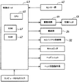
図2は、プリンタ100の制御ボード43を示すブロック図である。この制御ボード43は、CPU40と、ROM41と、RAM42とを有している。この制御ボード43には、センサー群40、ヘッド13を駆動させる駆動回路41、搬送部21、帯電ローラ15に接続されている後述するACバイアス供給部32等が接続されている。
FIG. 2 is a block diagram showing the
次に、本実施形態のプリンタのプリント動作について説明する。パーソナルコンピュータから画像情報などの信号が送られ、プリントを実行する。まず、給紙トレイ18から給紙ローラ19によって搬送ローラ10へ用紙が給紙される。給紙トレイ18から給紙された用紙は、ガイド部材22や加圧ローラ16に案内されて、ほぼ鉛直方向に搬送ベルト12に搬送される。搬送ベルト12の表面は帯電ローラ15により帯電させられており、用紙を静電的に搬送ベルト12に吸着させる。搬送ベルトに吸着した用紙は、案内ガイド22、加圧ローラに案内されてほぼ90°方向転換し、ほぼ水平状態でヘッド13と対向する位置に搬送される。搬送ベルト12に搬送された用紙がヘッド13と対向する位置に達したら、搬送ベルト12を停止して用紙の移動を停止する。そして、キャリッジ9が画像信号に応じて主走査線方向に往復移動しなが、停止した用紙の所定箇所に所定のインク液を吐出して一行分の画像を用紙に形成する。ここで、1行とは、ヘッド13が用紙へ記録可能な副走査線方向の範囲を言う。主走査線方向に一行分の記録が終了したら、搬送ベルト12を所定時間駆動させ、用紙を一行分排紙トレイ26方向に移動させて停止する。そして、上述同様、キャリッジ9が画像信号に応じて主走査線方向に往復移動しなが一行分の画像を形成する。このような工程を所定回数繰り返し行い、用紙に所望の画像をプリントする。このように用紙の搬送と停止を繰り返して用紙に画像を形成しているとき、用紙は、搬送ベルトに静電吸着しているので、用紙を安定してヘッドと対向する位置に搬送することができる。また、加圧ローラ16によって用紙を搬送ベルトに押し付けているので、用紙を搬送ベルト12に確実に静電吸着させることができる。所望の画像がプリントされた用紙は、分離爪17で搬送ベルト12から分離され、排紙ローラ25及び拍車24によって搬送され、排紙トレイ26に排出される。
両面プリントの場合は、用紙の一方の面に所望の画像をプリントしたら、搬送ベルト12を逆回転させ、用紙を反転機構30に搬送する。反転機構30で反転した用紙は、再びガイド部材22や加圧ローラ16に案内されて搬送ベルト12に搬送される。用紙がヘッド部13と対向する位置に達したら、上述同様の動作を行い用紙の他方の面に所望の画像をプリントする。そして、両面に所望の画像がプリントされた用紙は、分離爪17で搬送ベルト12から分離され、排紙ローラ25及び拍車24によって搬送されて排紙トレイ26に排出される。
Next, the printing operation of the printer of this embodiment will be described. A signal such as image information is sent from the personal computer, and printing is executed. First, paper is fed from the
In the case of duplex printing, when a desired image is printed on one side of the paper, the
次に、搬送ベルト12について詳細に説明する。図3の(a)、(b)は、搬送ベルト12の断面図である。搬送ベルト12は、図3(a)に示すように絶縁層30のみからなる一層構造の無端状ベルトや、図3(b)に示すような、絶縁層30と導電層31とからなる2層構造の無端状ベルトを採用することができる。2層構造の搬送ベルト12は、絶縁層30が帯電ローラ15や用紙と接触する外周面となり、導電層31が搬送ローラ12やテンションローラ11と接触する内周面となるように形成する。搬送ベルト12は、成形型によって、無端状に形成してもよいし、両端を接着などでつないで無端状にしても良い。絶縁層30は、PET、PEI、PVDF、PC、ETFE、PTFEなどの樹脂やエラストマーで導電制御材を含まない材料により形成される。この絶縁層30の体積抵抗率は、1012[Ωcm]以上が好ましく、より好ましくは1015[Ωcm]である。導電層31は、絶縁層30と同一の樹脂やエラストマーからなり、導電制御材としてカーボンを含有させて、体積抵抗率が105〜107[Ωcm]となるように調整されている。
帯電ローラ15は、体積抵抗率が106〜109[Ωcm]の導電性部材で形成されている。また、帯電ローラ15には、例えば±2kVのACバイアスを帯電ローラ15に印加するACバイアス供給部32が接続されている。帯電ローラ15に印加するACバイアスは、正弦波や三角波など種々の波形を採用することができるが、方形波とするのが好ましい。そして、帯電ローラ15によって搬送ベルト12の絶縁層30に交互に極性の異なる電圧が印加され、搬送ベルト12の絶縁層30に異なる極性の電荷が交互に帯電する。すると、図4(a)に示すように、搬送ベルト上には、搬送ベルト12上の正電荷から搬送ベルトに対して垂直方向に発生し、途中で屈曲して搬送ベルト12上の負電荷に向かうような微小電界が発生している。このとき、絶縁層30の体積抵抗率が1012[Ωcm]以上に設定されているので、絶縁層30上に帯電した正と負の電荷が移動して、互いの電荷を打ち消すことがない。よって、搬送ベルト12上に安定した正と負の帯電を交互に得ることができる。
Next, the
The charging
給紙トレイ18から搬送された用紙が搬送ベルト12に搬送されると、図4に示すように搬送ベルト12から発生する電界50によって用紙が誘電分極する。そして、この誘電分極によって対向する搬送ベルト12上の帯電極性と逆極性の電荷が用紙の搬送ベルト12側に発生し、用紙が搬送ベルト12上に静電吸着する。一方、用紙の印字面側は、搬送ベルト12から発生する電界の影響が少ないため、用紙の印字面側に搬送ベルトの電界によって発生する電荷は、搬送ベルト12側に発生する電荷に比べて少ない。搬送ベルトからの電界は、搬送ベルト上方で円弧状に屈曲している。このため、搬送ベルトの正帯電した部分と負帯電した部分の境界付近の電界は、用紙と平行となり用紙印字面に電位が発生しない。その結果、搬送ベルト12の正帯電した部分と負帯電した部分の境界付近に位置する用紙印字面側には、電荷が誘起されない。よって、用紙の印字面側に誘起される電荷が、搬送ベルト12側に誘起される電荷に比べて少なくなる。そして、時間が径過すると、対向する搬送ベルト12上の帯電極性と逆極性の真電荷が用紙内部から用紙の搬送ベルト側に除々に移動してきて、搬送ベルトの電界の影響を弱める。そして、搬送ベルトの電界の影響で誘電分極によって誘起した電荷量を減少させる。また、これと同時に対向する搬送ベルト12上の帯電極性と同極性の真電荷が用紙内部から用紙の印字面側に除々に移動してくる。
また、用紙の表面抵抗は1011〜1013[Ω/□]であり高抵抗であるが、導電性の性質を有しているため、印字面側に移動したきた真電荷は不安定な状態にある。そのため、時間とともに用紙の印字面側の真電荷は、異なる極性と引き付け合い消滅して用紙印字面側の電位を低下させる。一方、用紙の搬送ベルト側は、搬送ベルトからの強力な電界が作用しているため、用紙の印字面側のように真電荷が打ち消しあって消滅することがない。このように用紙印字面側の真電荷がなくなるため、用紙と搬送ベルトとの静電吸着力が高まる。また、用紙の印字面側の真電荷が打ち消されて、用紙の印字面側の電位が低くなった結果、用紙の印字面側とヘッドとの間で電界が発生しなくなる。よって、ヘッドから吐出したインク滴が電界の影響を受けて着弾位置にずれを生じたり、インクミストがヘッドに付着したりすることを抑制することができる。
When the paper transported from the
Further, the surface resistance of the paper is 10 11 to 10 13 [Ω / □], which is high resistance. However, since it has a conductive property, the true charge that has moved to the printing surface side is unstable. It is in. Therefore, over time, the true charge on the printing surface side of the sheet attracts and disappears with a different polarity, and lowers the potential on the printing surface side of the sheet. On the other hand, since a strong electric field from the conveyance belt acts on the conveyance belt side of the sheet, the true charges do not disappear due to the cancellation of the true charges unlike the printing surface side of the sheet. In this way, since there is no true charge on the paper printing surface side, the electrostatic attraction between the paper and the conveyor belt is increased. Further, as a result of the true charge on the printing surface side of the paper being canceled and the potential on the printing surface side of the paper being lowered, no electric field is generated between the printing surface side of the paper and the head. Therefore, it is possible to suppress the ink droplets ejected from the head from being shifted in the landing position due to the influence of the electric field and the ink mist from adhering to the head.
図5は、用紙表面電位の消滅時間と帯電周期長との関係を示すグラフである。搬送ベルト12への印加電圧は±2kVとし、このときの用紙表面電位を500V以下に設定した。なお、帯電周期長とは、図4に示すように、搬送ベルト12の負(正)帯電から正(負)帯電に切り替わる位置から、次の負(正)帯電から正(負)帯電に切り替わる位置までの距離である。また、帯電周期長は、搬送ベルト12の搬送スピードを変えることで異ならせた。すなわち、帯電周期長を短くする場合は、搬送スピードを遅くし、帯電周期長を長くする場合は、搬送スピードを早くした。図5からわかるように、表面電位の消滅時間は、帯電周期長の約2乗に比例することがわかる。よって、帯電周期長を短くすれば、電位消滅時間を短くできることがわかる。これは、帯電周期長が長くなればなるほど、正(負)極性の帯電部分が長くなる。その結果、正(負)極性の帯電部分の中央付近の真電荷が負(正)極性の真電荷と打ち消すために移動する距離が長くなり、真電荷が移動するための実質抵抗は高くなる。このように、正負極性の真電荷の距離が離れた結果、正と負の真電荷が引き合って打ち消し合うまでの時間が増加する。その結果、電位の消滅時間が長くなったと考えられる。
FIG. 5 is a graph showing the relationship between the disappearance time of the sheet surface potential and the charging cycle length. The voltage applied to the
図6は、実験より求めた表面抵抗率が異なる3種類の用紙表面電位と帯電周期長の関係を示すグラフである。用紙Aの表面抵抗率は、1.8×10¹³[Ω/□]であり、用紙Bの表面抵抗率は、1.2×1012[Ω/□]であり、用紙Cの表面抵抗率は、5×1011[Ω/□]である。また、搬送ベルト12への印加電圧は±2kVとし、用紙が搬送ベルト12に接触して、1.6秒後の表面電位を計測した。図6に示すように、用紙の表面抵抗率に係わらず、帯電周期長を短くすれば、用紙の表面電位を低くできることがわかる。これは、上述したように帯電周期長の短い方が、用紙表面電位の消滅時間が短いため、帯電周期長が短くなるにつれ、表面電位が低くなったと考えられる。また、帯電周期長が長いほど、用紙表面に発生する電界が増加し、用紙表面に移動する真電荷の量が多くなる。よって、帯電周期長が長いほど表面電位が高くなったと考えられる。また、表面抵抗率が高い用紙は、表面抵抗率が低い用紙に比べて表面電位が高いことがわかる。これは、用紙の表面抵抗が高いほど、用紙表面の真電荷が移動しにくくなり、単位時間あたりの真電荷の移動量が小さくなる。その結果、用紙表面の真電荷が打ち消される時間が長くなるため、表面抵抗率が高い用紙は、表面抵抗率が低い用紙に比べて表面電位が高くなったと考えられる。
FIG. 6 is a graph showing the relationship between the three types of paper surface potentials having different surface resistivity values obtained from experiments and the charging cycle length. The surface resistivity of the paper A is 1.8 × 10 13 [Ω / □], the surface resistivity of the paper B is 1.2 × 10 12 [Ω / □], and the surface resistivity of the paper C. Is 5 × 10 11 [Ω / □]. The voltage applied to the
図5、図6の結果から、帯電周期長を短くすれば、用紙の印字面側の電位を低くすることができ、インク滴が電界の影響を受けて着弾位置のずれを生じたり、インクミストがヘッドの吐出口に付着したりすることを抑制できる。帯電周期長を短くする方法としては、搬送ベルト12の搬送スピードを遅くすることが考えられる。しかしながら搬送ベルト12の搬送スピードを遅くすると、プリント時間が遅くなってしまい、高速プリントをすることができない。また、ACバイアスの1周期の時間を短くすることも考えられるが、ACバイアス供給部32が0Vから±2kVまで電圧を立ち上げるのに10mSec必要であり、少なくと一周期40mSec必要となる。ACバイアス供給部32の電源供給容量を増加させることで、電圧立ち上げ時間を速くすることも可能であるが、この場合ACバイアス供給部32が大型化して、装置の大型化、コストアップに繋がってしまう。しかしながら、本実施形態においては、帯電ローラ15とヘッド13との間に用紙印字面側の真電荷を除去する除電部材29を設けて用紙印字面側の真電荷を除去している。これにより、高速プリントのために搬送スピードを速めて帯電周期長が長くなっても、用紙がヘッド13と対向するまでの間に用紙の印字面側の電位を低くすることができる。よって、高速プリントができ、しかもヘッドから吐出したインク滴が電界の影響を受けて着弾位置にずれを生じたり、インクミストがヘッド吐出口に付着したりすることを抑制することができる。
From the results shown in FIGS. 5 and 6, if the charging cycle length is shortened, the potential on the printing surface side of the paper can be lowered, and the ink droplets are affected by the electric field, causing the landing position to shift, or the ink mist. Can be prevented from adhering to the ejection opening of the head. As a method for shortening the charging cycle length, it is conceivable to reduce the conveying speed of the conveying
上記、用紙印字面側の真電荷を除去する除電部材29としては、除電ブラシや導電性ローラ等を用いることができる。また、搬送ベルト12に印加するACバイアスと半周期ずらしたACバイアスを用紙印字面側に印加させる部材を除電部材29として用いることもできる。
As the charge eliminating member 29 for removing the true charge on the paper printing surface side, a charge eliminating brush, a conductive roller, or the like can be used. In addition, a member that applies an AC bias that is shifted from the AC bias applied to the
まず、除電ブラシを除電部材29として適用した例について実施例1に基づき説明する。図7は、除電部材として、除電ブラシ129を用いた概略構成図である。図7に示す、除電ブラシ129は、導電性の材質のものが使用される。例えば、直径8〜20μm程度のステンレス繊維や、アクリル、ポリエステル等の樹脂繊維に金属メッキを施したものを使用することができる。また、樹脂にカーボン、金属粉等を炭化し、導電性を付与した炭素繊維等を使用することができる。除電ブラシの体積抵抗は、1011[Ωcm]以下、望ましくは108[Ωcm]以下とする。本実施形態の除電ブラシは、太さ15μm、長さ10mmのナイロン(登録商標)にカーボン繊維を混入したものを用いた。また、本実施形態の除電ブラシは、帯電周期長の(1/2)以上の幅の除電ブラシとしている。
First, an example in which the static elimination brush is applied as the static elimination member 29 will be described based on the first embodiment. FIG. 7 is a schematic configuration diagram using a
次に、図8に示す帯電周期長の(1/2)以下の幅狭の除電ブラシ129aと、図7に示す帯電周期長の(1/2)以上の幅広の本実施形態の除電ブラシををそれぞれ、本実施形態のプリンタ設置して除電効果を調べた。その結果を図9に示す。なお、図9に示す現状とは、除電ブラシを設けなかった場合の結果である。図9に示すように、幅狭の除電ブラシ129aに比べて幅広の除電ブラシ129の方が、除電効果が高いことがわかる。幅狭の除電ブラシ129aによって用紙から除去された真電荷は、除電ブラシに接続されたアースに移動することで真電荷が打ち消される。このため、除電ブラシの除電までに時間がかかり、除電ブラシが帯電しやすい。除電ブラシが帯電してしまうと、電荷除去能力が低下してしまう。その結果、幅広の除電ブラシ129に比べ、除電効果が低下したと考えられる。一方、幅広の除電ブラシ129は、搬送方向に対して帯電周期長の1/2以上の幅を有しているので、用紙の負帯電部分と正帯電部分とを跨って接触する。つまり、ひとつの除電ブラシ129で負の真電荷と正の真電荷を除去することとなる。その結果、除電ブラシ内で電荷が打ち消されるので、除電ブラシが帯電しにくい。よって、除電能力が低下しないので、幅狭の除電ブラシに比べて除電効果が高くなったと考えられる。
Next, the
次に、除電ブラシの設置位置について説明する。図10は、除電ブラシの設置位置を示す概略図であり、図中のA、B、Cは、除電ブラシの設置位置を示している。図10に示すA、B、Cの各位置における除電ブラシの除電効果を抵抗の異なる2つの用紙を用いて調べた。その結果を図11に示す。用紙Aは、表面抵抗率が1.8×1013[Ω/□]であり、用紙Bは、表面抵抗率が1.2×1012[Ω/□]である。また、図11中の現状とは、除電ブラシを設けない場合の用紙の表面電位である。また、表面電位の測定はヘッドが位置する位置で行った。図11に示すように用紙の種類に関係なくヘッドに近い除電ブラシの方が、除電効果が高いことがわかる。これは、搬送ベルト12に用紙が吸着したばかりのときは、まだ用紙内部の真電荷が電界によって用紙表面に十分析出していない。このため、搬送ベルト12に用紙が吸着したばかりのときに用紙に接触するAの位置に配置した除電ブラシAは、十分な除電効果を得ることができなかったと考えられる。また、用紙が搬送ローラの曲率に沿うようにして移動した後に用紙に接触するBの位置に配置した除電ブラシBは、除電ブラシAに比べて除電効果が高い。これは、搬送ベルト12に用紙が吸着していた時間がAの位置に比べて長いため、その分用紙中の真電荷が表面に析出したため、除電効果が高まったと考えられる。また、真電荷は、振動や熱などのエネルギーによって移動が促進される。Aの位置からBの位置へ移動する間に、用紙は搬送ローラの曲率に沿って移動するため、用紙が変形する。このような用紙の変形によって真電荷の移動が促進され、表面へ析出する真電荷が多くなり、Aの位置の除電ブラシAに比べBの位置の除電ブラシBの方の除電効果が高まったと考えられる。また、Cの位置にある除電ブラシCは、除電ブラシBに比べて除電効果が高い。これは、搬送ベルト12に用紙が吸着して時間が径過したため、用紙中の真電荷の多くが表面に析出し、除電効果が高まったと考えられる。また、キャリッジを移動させる駆動モータから発する熱や、回路の熱などによって、用紙中の真電荷の移動が促進された結果、用紙中の真電荷の多くが表面に析出し、Cの位置にある除電ブラシCの除電効果が高まったとも考えられる。
Next, the installation position of the static eliminating brush will be described. FIG. 10 is a schematic diagram showing the installation position of the static elimination brush, and A, B, and C in the figure indicate the installation position of the static elimination brush. The neutralizing effect of the neutralizing brush at each of the positions A, B, and C shown in FIG. 10 was examined using two sheets having different resistances. The result is shown in FIG. The sheet A has a surface resistivity of 1.8 × 10 13 [Ω / □], and the sheet B has a surface resistivity of 1.2 × 10 12 [Ω / □]. Also, the current state in FIG. 11 is the surface potential of the paper when no static eliminating brush is provided. The surface potential was measured at the position where the head was located. As shown in FIG. 11, it can be seen that the neutralization brush closer to the head has a higher neutralization effect regardless of the type of paper. This is because when the sheet is just adsorbed on the conveying
上記実験により除電ブラシ129は、ヘッド近傍に設けた方が除電効果を高めることができることがわかる。しかし、ヘッド近傍に除電ブラシ129を設けると、両面プリント時に搬送ベルト12を逆回転させ用紙を反転機構30に搬送する際、用紙の印字面が十分乾いていない場合があり、除電ブラシ129によって印字面が汚されることがある。そこで、除電ブラシ129をヘッド近傍に設ける場合は、搬送ベルト12を逆回転させた時に除電ブラシを用紙から離間させる離間機構51を設ける。図12(a)、(b)は、離間機構51を説明する概略構成図であり、図12(a)は、搬送ローラ10の正回転時の状態を示す図であり、図12(b)は、搬送ローラ10の逆回転時の状態を示す図である。図12に示すように、搬送ローラ10の一端に第1のギヤ52が取り付けられている。第1のギヤ52には、第2のギヤ53が噛み合っており、第2のギヤ53には、第3のギヤ54が噛み合っている。第3のギヤ54には、バー55を介して除電ブラシ129が取り付けられている。また、離間機構51には、搬送ローラ10が正回転時にバー55と当接する第1の当接部56と、搬送ローラ10が逆回転時にバー55と当接する第2の当接部57がそれぞれ設けられている。
From the above experiment, it can be seen that the
図12(a)に示すように、搬送ローラ10の正回転時には、搬送ローラ10の回転駆動力が第1、第2のギヤ52、53を介して第3のギヤ54の伝達される。すると、除電ブラシ129が図中時計周りに回転し、バー55が第1の当接部56と当接する。これにより、除電ブラシ129が必要以上に用紙側に移動することが防止される。バー55が第1の当接部56に当接して除電ブラシ129が移動しなくなると、各ギヤにトルクがかかる。すると、図示しないクラッチを切って、搬送ローラ10の回転駆動力が除電ブラシ129に伝達されなくなる。
用紙を反転機構部30に送るために搬送ローラ10が逆回転すると、図示しないクラッチを繋いで、搬送ローラ10の駆動力が各ギヤを介して除電ブラシ129に伝達される。すると、図12(b)に示すように、除電ブラシ129が反時計周りに回転し、用紙から離間する。そして、バー55が第2の当接部57に当接して除電ブラシ129が必要以上に移動しないようにする。バー55が第2の当接部57に当接して除電ブラシ129が移動しなくなると、ギヤにトルクがかかる。すると、図示しないストッパ手段が作動して、除電ブラシ129を図12(b)に示す位置に維持する。これとともに図示しないクラッチを切って、搬送ローラ10の駆動力が除電ブラシ129に伝達されないようにする。そして、用紙が反転機構30に送られ、搬送ローラ10の正回転すると、図示しないストッパ手段のストッパが解除される。これとともに図示じないクラッチが繋がって、搬送ローラの駆動力が各ギヤを介して除電ブラシ129に伝達される。すると、除電ブラシ129が移動し第1の当接部56に当接して除電ブラシ129が用紙と接触する。
これにより、用紙を反転機構部30に送るために搬送ローラ10を逆回転させ用紙が引き戻されるとき、除電ブラシ129は用紙から離間する。その結果、用紙の印字部が除電ブラシ129によって汚されることがない。
As shown in FIG. 12A, during the forward rotation of the
When the conveying
As a result, when the
次に、実施例2の除電部材について説明する。この除電部材は、上記除電ブラシ129に搬送ベルト上の帯電極性と逆極性のバイアスを印加することで用紙の印字面側の電荷を除去するようにしている。図13は、この実施例の概略構成図である。図12に示すように、除電ブラシ129は、帯電周期長をXとすると、帯電ローラ15から1.5Xの位置に配置され、帯電周期長Xに対して(1/2)Xずらしている。また、除電ブラシ129は、抵抗Rを介して帯電ローラ15と同一のACバイアス供給部32に接続されている。この抵抗Rによって除電ブラシ129に印加される電圧は、帯電ローラ15に印加される電圧の約(1/2)程度弱められる。除電ブラシ129と帯電ローラ15とは同一電源に接続されているので、同一のタイミングで同一極性のバイアスがそれぞれ除電ブラシ129と帯電ローラ15とに印加される。除電ブラシ129は、上述のとおり、帯電ローラ15から1.5Xの位置に配置し、帯電周期長に対して(1/2)Xずらしている。よって、帯電ローラ15と同一のタイミングで同一極性のバイアスを除電ブラシ129に印加すれば、このとき除電ブラシ129と対向する位置にある搬送ベルト12上の帯電極性と除電ブラシ129に印加される極性とを異ならせることができる。図4に示すように、搬送ベルト12上の帯電極性と用紙印字面側の真電荷の極性は、同極性となっている。このため、除電ブラシ129と対向する搬送ベルト12上の帯電極性と逆極性のバイアスを除電ブラシ129に印加すれば、用紙印字面側の真電荷が除電ブラシ129に印加されたバイアスと打ち消し合い、用紙印字面側の真電荷を消滅することができる。また、用紙印字面側の電位は、搬送ベルト12の電位に比べ弱いので除電ブラシ129に印加する電圧値を帯電ローラ15の電圧値と同一とすると、除電ブラシ129によって用紙印字面側を帯電させてしまう場合がある。しかし、実施例2においては、除電ブラシ129に印加する電圧値を帯電ローラ15の電圧値に比べて約(1/2)程度弱めているので、除電ブラシ129によって用紙印字面側を帯電させてしまうことなく、用紙印字面側の真電荷を除去することができる。また、帯電ローラ15から除電ブラシ129までの距離を、帯電周期長Xの整数倍に対して(1/2)Xずらすことで、同一のACバイアス供給電源を用いることができる。これにより、装置の省スペース化、コストを低減することができる。また、上記帯電周期に合うように電圧の制御をする必要がない。これにより、制御の複雑化や装置の複雑化を抑制できる。
実施例2の除電ブラシ129は、図13に示すように搬送ローラ10と対向する位置に設けた例について説明したが、これに限られない。例えば、この除電ブラシ129をヘッドの近傍に設ければ、除電効果を高めることができる。
Next, the static elimination member of Example 2 is demonstrated. The charge removing member applies a bias having a polarity opposite to the charge polarity on the conveying belt to the
Although the
次に、実施例3の除電部材について説明する。この実施例3の除電部材は、図14に示すように加圧ローラ16や案内ローラ28に搬送ベルト上の帯電極性と逆極性のバイアスを印加して除電ローラ29として、用紙の印字面側の真電荷を除去するようにしている。図14(a)は、案内ローラ28を除電ローラ29とした例であり、図14(b)は、加圧ローラ15を除電ローラ29とした例である。図14(a)に示す除電ローラ29においても、帯電周期長をXとしたとき、帯電ローラ15から除電ローラ29までの距離を1.5Xとして、(1/2)ずらしている。また、図14(b)に示す除電ローラ29においても、帯電ローラ15から除電ローラ29までの距離を3.5Xとして、(1/2)ずらしている。また、図14(a)、(b)に示す除電ローラ29は、抵抗Rを介して帯電ローラ15と同一のACバイアス供給部32に接続されている。この抵抗Rによって除電ローラ29に印加される電圧は、帯電ローラ15に印加される電圧の約(1/2)程度弱められる。除電ローラ29と帯電ローラ15とは同一電源に接続されているので、同一のタイミングで同一極性のバイアスがそれぞれ除電ローラ29と帯電ローラ15とに印加される。除電ローラ29は、上述のとおり、帯電周期長Xに対して(1/2)Xずらしている。よって、帯電ローラ15と同一のタイミングで同一極性のバイアスを除電ローラ29に印加すれば、除電ローラ29と対向する搬送ベルト上の帯電極性と逆極性のバイアスを除電ローラ29に印加することとなる。用紙印字面側には、搬送ベルト12上の帯電極性と同一極性の真電荷が析出するので、除電ローラ29に搬送ベルト12上の帯電極性と逆極性のバイアスを印加することで、用紙印字面側の真電荷を打ち消すことができる。
Next, the static elimination member of Example 3 is demonstrated. As shown in FIG. 14, the neutralizing member of the third embodiment applies a bias having a polarity opposite to the charging polarity on the conveying belt to the
次に、除電ローラ29の設置位置について調べた。図15は、除電ローラの設置位置を示す概略図であり、図中のA、B、Cは、除電ローラ29の設置位置を示している。図15に示すA、B、Cの各位置における除電ローラ29の除電効果を抵抗の異なる2つの用紙A、Bを用いて調べた。用紙Aは、表面抵抗率が1.8×10¹³[Ω/□]であり、用紙Bは、表面抵抗率が1.2×1012[Ω/□]である。その結果を図16に示す。なお、図16中の現状とは、除電ローラを設けない場合の用紙の表面電位である。また、表面電位の測定はヘッドが位置する位置で行った。図16に示すように、除電ローラ29においても、上述の除電ブラシ同様に、用紙が搬送ローラ10の曲率に沿って移動する前の位置Aに配置した除電ローラAに比べ、用紙が搬送ローラ10の曲率に沿って移動した後の位置B、Cに配置した除電ローラB、Cの方の除電効果が高いことがわかる。これは、除電ブラシと同様に、用紙が搬送ローラ10の曲率に沿って移動した結果、用紙中の真電荷の移動が促進され、用紙表面に多くの真電荷が析出した後に用紙表面の真電荷を除去したためと考えられる。
Next, the installation position of the static eliminating roller 29 was examined. FIG. 15 is a schematic diagram showing the installation position of the static elimination roller, and A, B, and C in the figure indicate the installation positions of the static elimination roller 29. The neutralization effect of the neutralization roller 29 at each of the positions A, B, and C shown in FIG. 15 was examined using two sheets A and B having different resistances. The sheet A has a surface resistivity of 1.8 × 10 13 [Ω / □], and the sheet B has a surface resistivity of 1.2 × 10 12 [Ω / □]. The result is shown in FIG. Note that the current state in FIG. 16 is the surface potential of the paper when no static eliminating roller is provided. The surface potential was measured at the position where the head was located. As shown in FIG. 16, in the static elimination roller 29, similarly to the above-described static elimination brush, the paper is higher in the
このように、除電ローラ29においても、ヘッド近傍に設けた方が、除電効果が高いことがわかる。しかし、除電ブラシ129同様、両面プリント時に除電ローラ29が用紙の印字面を汚す場合がある。そこで、除電ローラ29においても反転機構部30に用紙を搬送する際、除電ローラ29が用紙から離間する除電ブラシ同様の離間機構を設ける。すなわち、上述した図12の離間機構51のバー55に取り付けられている除電ブラシ129を除電ローラ29に変える。これにより、反転機構部30に用紙を搬送する際、用紙から除電ローラ29が離間する。よって、用紙の印字面を汚すことがない。
Thus, it can be seen that the neutralization roller 29 also has a higher neutralization effect if it is provided near the head. However, like the
上記実施形態のプリンタにおいては、搬送ベルト12を停止して用紙へ画像を記録している。搬送ベルト12が停止している状態のときに帯電ローラ15や除電部材29等にACバイアスを印加し続けていると帯電周期長にずれが生じてしまう場合がある。すなわち、図17に示すように、搬送ベルト12が移動を再開するタイミングによっては、帯電周期長Xが短いあるいは長い部分X´が生じてしまう。その結果、除電部材29から用紙へ印加するACバイアスの極性と搬送ベルトとの極性がずれ、用紙表面の真電荷を除去できない場合がある。また、搬送ベルト12が停止中は除電部材29から用紙の同じ部分に電圧が連続して印加されるため、逆に除電部材29から用紙へ電荷が供給されてしまう場合がある。また、帯電ローラ15から搬送ベルト12の同じ部分に電圧が連続して印加されるため、搬送ベルト12が発熱してしまう場合がある。このように搬送ベルト12が発熱すると、ピンホールを誘発しリークに発展する場合があった。
そこで、実施例4においては、図18に示すように、除電部材29とACバイアス供給部32、および帯電ローラ15とACバイアス供給部32との間にそれぞれスイッチ61、62を設けて、搬送ベルト12が停止するときは、各スイッチ61、62をOFFするようにする。図19は、スイッチのON、OFFのタイミングを示す図である。図19に示すように、搬送ベルト12の移動が停止する(図19のA)と、各スイッチ61、62をOFFにして帯電ローラ15および除電部材29へのACバイアスの供給を停止する。このときの帯電ローラおよび除電部材に印加されていた電圧の極性およびこの極性の電圧の印加時間を記憶しておく。そして、ACバイアス供給部32が上記記憶した電圧の極性およびこの極性の電圧の印加時間になったとき(図19のB)に各スイッチ61、62をONにし、帯電ローラ15および除電部材29にACバイアスを供給する。これと同時に搬送ベルトの移動を再開させる。これにより、図19に示すように、搬送ベルトの帯電周期にずれが生じることがない。
In the printer of the above embodiment, the conveying
Therefore, in the fourth embodiment, as shown in FIG. 18, switches 61 and 62 are provided between the charge removal member 29 and the AC
図20は、上記スイッチ61、62のタイミングを制御するフローチャトである。図20に示すように、まず、例えばパーソナルコンピュータなどからプリンタに画像信号が入力されて印刷を開始する(S1)。印刷が開始されると、搬送ローラ10の駆動スイッチがONとなり搬送ローラが駆動する(S2)。この搬送ローラが駆動した結果、搬送ローラとテンションローラとに張架されている搬送ベルト12が駆動する。次に、ACバイアス供給部32と帯電ローラ15とのスイッチ62がONとなり、帯電ローラ15にACバイアスを印加する(S3)。一方、印刷が開始されると、給紙動作が作動して、給紙トレイ18から用紙が搬送ベルト12へ搬送される(S4)。そして、用紙先端が除電部材29に到達したかどうかを調べる(S5)。用紙先端が除電部材29に到達したら(S5YES)、除電部材29とACバイアス供給部32とのスイッチ61をONにして除電部材29にACバイアスを印加する(S6)。そして、用紙先端がヘッド13と対向する位置まで搬送されたら、記録動作を開始する(S7)。具体的には、搬送ベルト12の移動を停止しキャリッジ9を主走査線方向に移動させて用紙に一行分の画像を形成する。記録動作が開始されたら、搬送ベルト12が停止中であるかどうか調べる(S8)。搬送ベルト12の移動が停止している場合(S8YES)は、帯電ローラ15、除電部材29の各スイッチ61、62をOFFにして(S9)、ACバイアスを印加しないようにする。また、このときの帯電ローラ15および除電部材29に印加されていた電圧の極性およびこの極性の電圧の印加時間を記憶しておく。次に、一行分の画像を用紙に記録し終わり、搬送ベルト移動の信号があるかどうか調べる(S10)。搬送ベルト移動の信号がある場合、(S10YES)は、ACバイアスが記憶された電圧の極性およびこの極性の電圧の印加時間となるタイミングで帯電ローラ15および除電部材29の各スイッチ61、62をONにする(S11)。帯電ローラ15、除電部材29にACバイアスが印加されると同時に、搬送ベルト12の移動を開始する(S12)。次に、記録終了かどうかを調べる(S13)。次行に記録する画像がある場合(S13NO)は、S8以降のステップを繰り返す。一方、次行に記録する画像がない場合(S13YES)は、記録終了であるので、排出動作を実行し(S14)、印刷を終了する(S15)。また、記録動作が開始される(S7)と、用紙後端が除電部材29を通過したかどうか調べる(S16)。用紙後端が除電部材29を通過した場合(S16)は、帯電ローラ15、除電部材29の各スイッチ61、62をOFFにして(S17)、印刷を終了する(S15)。
FIG. 20 is a flowchart for controlling the timing of the switches 61 and 62. As shown in FIG. 20, first, for example, an image signal is input to a printer from a personal computer or the like, and printing is started (S1). When printing is started, the drive switch of the
このように、搬送ベルト12が停止中は、除電部材29および帯電ローラ15にACバイアスが印加されれないので、同じ部分に連続して電圧が印加されない。これにより、除電部材29から用紙へ電荷が供給されてしまったり、搬送ベルト12が発熱してピンホールを誘発しリークに発展しまったりすることがない。また、スイッチ61、62をOFFにしたときのACバイアスの極性およびこの極性の印加時間を記憶し、ACバイアス供給部32のACバイアスが上記記憶した極性およびこの極性印加時間となったときにスイッチONにするとともに搬送ベルト12の駆動を再開するようにしている。これにより、帯電周期がずれることがなく、用紙表面の電荷を確実に除去することができる。
As described above, while the conveying
また、用紙の種類によって、各スイッチ61、62をON、OFFさせるようにしても良い。例えば、OHPなどの高抵抗用紙の場合、搬送ベルトの電界により、用紙が誘電分極した後、用紙の印字面側に真電荷が移動するまで時間がかかってしまう。その結果、除電部材から用紙表面に打ち消し合う以上の電荷が付与され、逆に用紙表面を帯電させる場合があった。また、用紙がヘッドと対向する位置に到達するまでに十分な真電荷が移動せず、搬送ベルトの電界の影響が弱まらない。その結果、用紙の印字面側には、誘電分極によって誘起された電荷が存在し用紙印字面側に電位が発生してしまう。よって、用紙とヘッドとの間に電界が発生してしまう。そこで、各スイッチ61、62をON、OFFを制御してヘッドと用紙との間に電界が発生しないようにしている。具体的には、OHP用紙が搬送されてきて一定時間径過したタイミングで帯電ローラのスイッチ62をOFFにして、OHP用紙先端に搬送ベルトの電界が働くようにする。そして、OHPの後端が搬送ベルトと接触するタイミングより早いタイミングで帯電ローラのスイッチ62をONにして用紙後端に搬送ベルトの電界が働くようにする。その結果、OHP用紙の先端と後端のみが搬送ベルトの電界の影響を受けて搬送ベルトに静電吸着する。これにより、OHP用紙を高精度に搬送することができる。また、OHPの画像が記録される部分は、搬送ベルトの電界の影響がない。そのため、OHPの画像が記録される部分は、用紙とヘッドとの間に電界が発生してしまうことがない。また、OHP用紙が搬送される際は除電部材のスイッチ61をOFFにして、除電部材29にバイアスを印加させないように制御する。これにより、用紙に除電部材から必要以上に電荷が付与されることが防止され、除電部材によって用紙の印字面側が帯電することを防止することができる。 Further, the switches 61 and 62 may be turned on and off depending on the type of paper. For example, in the case of high resistance paper such as OHP, it takes time until the true charge moves to the printing surface side of the paper after the paper is dielectrically polarized by the electric field of the conveyor belt. As a result, there is a case where a charge more than the surface of the sheet is canceled out from the charge eliminating member, and the sheet surface is charged on the contrary. In addition, sufficient true charge does not move until the paper reaches a position facing the head, and the influence of the electric field of the conveyor belt is not weakened. As a result, charges induced by dielectric polarization exist on the printing surface side of the paper, and a potential is generated on the paper printing surface side. Therefore, an electric field is generated between the paper and the head. Therefore, the switches 61 and 62 are controlled to be ON and OFF so that an electric field is not generated between the head and the paper. Specifically, the charging roller switch 62 is turned OFF at a timing when the diameter of the OHP sheet is conveyed and the diameter of the OHP sheet is exceeded for a certain period of time, so that the electric field of the conveying belt acts on the leading edge of the OHP sheet. Then, the charging roller switch 62 is turned ON at a timing earlier than the timing at which the rear end of the OHP contacts the transport belt so that the electric field of the transport belt acts on the rear end of the sheet. As a result, only the leading edge and the trailing edge of the OHP sheet are electrostatically attracted to the conveying belt under the influence of the electric field of the conveying belt. Thereby, OHP paper can be conveyed with high accuracy. Further, the portion where the OHP image is recorded is not affected by the electric field of the conveyor belt. Therefore, an electric field does not occur between the paper and the head in the portion where the OHP image is recorded. Further, when the OHP sheet is transported, the neutralization member switch 61 is turned OFF to control so that no bias is applied to the neutralization member 29. Thereby, it is possible to prevent the sheet from being charged more than necessary from the charge removal member, and to prevent the sheet from being printed on the printing surface side by the charge removal member.
上記実施形態においては、除電ブラシ129および除電ローラ29などの除電部材を一箇所に設けているが、除電部材を複数設けても良い。また、加圧ローラ16や案内ローラ28を導電性のある材料で形成しアースに落として用紙の残留電荷を除去するようにしても良い。さらに、搬送ベルトの移動方向に対して除電部材よりも上流側にヒータなどの加熱手段を設け、用紙を加熱するようにしてもよい。このように用紙を加熱することで、用紙内部の真電荷が印字面側に移動するのを促進することができる。よって、用紙が加熱された後に印字面側の電荷を除電部材によって除去することで、用紙内部の真電荷を除去することができる。その結果、除電部材で印字面側の電荷を除去した後に、用紙内部から印字面側に移動してくる真電荷の量を抑えることができ、ヘッドと用紙との間に電界が形成されることが抑制され、インク滴が帯電することを抑制することができる。
In the above embodiment, the neutralizing members such as the neutralizing
以上、本実施形態の画像形成装置によれば、搬送ベルトにACバイアスを印加して、用紙の印字面側に誘起する電荷量を減少させるとともに、用紙の印字面側に正極性と負極性の異なる電荷を誘起させ、お互いに打ち消し合わせて用紙印字面側の電荷を除去する。さらに、搬送ベルトに静電吸着した用紙がヘッドと対向する位置に到達するまでの間に用紙の印字面側の電荷を除電部材によって除去する。これにより、搬送スピードが上がっても、ヘッドと対向する位置に到達した用紙の印字面側にほとんど電荷を存在させないようにすることができる。その結果、用紙とヘッドとの間に電界が発生することが抑制され、ヘッドから吐出したインクが帯電することが抑制される。よって、高速プリントにおいても、インク滴の着弾位置がずれることがなく、インクミストがヘッドの吐出口に付着して正常なインクの吐出を妨げることが抑制される。よって、高速プリントにおいても、高品位な画像を得ることができる。
また、本実施形態においては、除電部材を導電性の部材で構成している。これにより、用紙印字面側の電荷をスムーズに除去することができる。
また、除電部材を加圧ローラとすることで、用紙を搬送ベルトに押し付けるとともに、用紙の印字面の電荷を除去することができる。
また、除電部材を導電性ブラシとしての除電ブラシとすることで、用紙印字面側の電荷をスムーズに除去することができる。
また、除電ブラシの幅を帯電周期長の(1/2)以上とすることで、用紙の負帯電部分と正帯電部分とを跨って接触することができる。これにより、ひとつの除電ブラシで負の電荷と正の電荷を除去することができる。その結果、除電ブラシ内で電荷が打ち消されるので、除電ブラシが帯電しにくい。よって、除電能力が低下しないため、用紙印字面側の電荷をさらに、スムーズに除去することができる。
また、除電部材と対向する搬送ベルト上の帯電極性と逆極性のバイアスを除電部材に印加することで用紙の印字面側の電荷を除去する。搬送ベルトの負帯電している部分に対向する用紙の印字面側には負の電荷が表面に移動し、搬送ベルトの正帯電している部分に対向する用紙の印字面側には正の電荷が表面に移動する。よって、除電部材と対向する搬送ベルト上の帯電極性と逆極性のバイアスを除電部材に印加することで、除電部材と対向する用紙の印字面側の電荷の極性と逆極性の電圧が除電部材に印加されることとなる。その結果、用紙の印字面側の電荷が除電部材の電荷と打ち消しあって、用紙の印字面側の電荷を除去することができる。
また、帯電周期長をXとしたとき、帯電ローラから除電部材までの搬送ベルトの移動距離は、(a−0.5)Xとなるようにする(aは整数)。これにより、帯電ローラから除電部材までの搬送ベルトの移動距離が帯電周期長の整数倍から半周期ずれる。すると、帯電ローラと同一のタイミングで同一極性のバイアスを除電部材に印加すれば、このとき除電ブラシと対向する位置にある搬送ベルト上の帯電極性と除電ブラシに印加される極性とを異ならせることができる。よって、帯電ローラと除電部材とを同一の印加手段であるACバイアス供給部を用いることができる。よって、装置の省スペース化、コストを低減することができる。また、上記帯電周期に合うように電圧の制御をする必要がない。これにより、制御の複雑化や装置の複雑化を抑制できる。
また、搬送ベルトが停止中のときは、帯電ローラおよび除電部材に電圧を印加しないようにしている。これにより、帯電ローラから搬送ベルトの同じ部分に電圧が印加されることがない。よって、搬送ベルトが発熱してピンホールを誘発しリークに発展しまったりすることがない。また、除電部材から用紙の同じ部分に連続して電圧が印加されることがないので、除電部材29から用紙へ電荷が供給されて用紙の印字面側を帯電させてしまうことを防止することができる。
また、用紙がOHPなどの高抵抗部材の場合は、除電部材にバイアスを印加させないように制御する。これにより、用紙に除電部材から必要以上に電荷が付与されることが防止され、除電部材によって用紙の印字面側が帯電することを防止することができる。また、帯電ローラのスイッチを制御して、OHP用紙の先端と後端のみを搬送ベルトに静電吸着させるようにする。OHP用紙を搬送ベルトに静電吸着させることができる。高精度にOHP用紙を搬送することができる。また、OHP用紙の画像が記録される部分に対向する搬送ベルトには、搬送ベルトに電荷が付与されていない。これにより、OHP用紙の画像が記録される部分は、搬送ベルトの電界の影響を受けることがなく、静電分極により用紙の印字面側に電荷が誘起されることがない。その結果、OHP用紙の画像が記録される部分は、ヘッドと用紙との間に電界が発生することがなく、良好な画像を得ることができる。このように、OHPなどの高抵抗で真電荷が移動しにくく、ヘッドと対向するまでの間に搬送ベルトの電界の影響を弱めることができない用紙でも、高精度に用紙を搬送でき、また、高品位な画像を得ることができる。
また、用紙が搬送ベルトに静電吸着して搬送ローラ10の曲率に沿って移動した後に用紙の印字面側の電荷を除電部材によって除去するようにする。用紙が搬送ベルトに静電吸着すると、搬送ベルトの電界によって用紙が分極される。その結果、用紙の印字面側には、搬送ベルトの帯電極性と同極性の真電荷が移動し、用紙の搬送ベルト側には搬送ベルトの帯電極性と反対の極性の真電荷が移動する。しかし、用紙内部にある真電荷が印字面側に移動してくるのに時間がかかる。このため、除電部材で印字面側の電荷を除去した後に用紙内部の真電荷が印字面側に移動してくる場合がある。その結果、除電部材で印字面側の電荷を除去したにもかかわらず、ヘッドと対向する位置に搬送された用紙の印字面側に電荷が存在してしまう場合があった。
一方、用紙が搬送ローラの曲率に沿って移動することで、用紙内部の真電荷の移動が促進する。この結果、用紙が搬送ローラの曲率に沿って移動した後は、用紙内部の真電荷が印字面側に移動してくる。よって、用紙が搬送ローラの曲率に沿って移動した後に印字面側の電荷を除電部材によって除去することで、用紙内部の真電荷をも除去することができる。その結果、除電部材で印字面側の電荷を除去した後に、用紙内部から印字面側に移動してくる真電荷の量を抑えることができる。よって、ヘッドと対向する位置に搬送された用紙の印字面側には、真電荷がほとんど存在していない。これにより、ヘッドと用紙との間に電界が形成されることが抑制され、インク滴が帯電することを確実に抑制することができる。
また、除電部材をヘッド近傍に設けることで、除電部材によって用紙表面の電荷が除去されるまで用紙が搬送ベルト12に吸着する時間を長くすることができる。その結果、除電部材に到達するまでに用紙中の真電荷を用紙表面に多く析出させることができ、除電効果を高めることができる。
また、用紙を反転機構30に搬送させるために搬送ベルトを逆回転させたときに除電部材を用紙から離間させる離間機構を設けている。これにより、用紙の印字部が除電部材によって汚されることがなくなる。
また、搬送ベルトの移動方向において除電部材よりも上流側に加熱部材を備える。これにより、用紙が除電部材に到達する前に加熱部材によって用紙内部の真電荷の移動を促進させて、用紙内部の真電荷を印字面側に移動させることができる。その結果、除電部材で用紙内部の真電荷をも除去することができる。よって、ヘッドと対向する位置に搬送された用紙の印字面側に真電荷がほとんど存在しなくなる。これにより、ヘッドと用紙との間に電界が形成されることが抑制され、インク滴が帯電することを確実に抑制することができる。
As described above, according to the image forming apparatus of the present embodiment, an AC bias is applied to the conveying belt to reduce the amount of charge induced on the printing surface side of the paper, and positive and negative polarity on the printing surface side of the paper. Different charges are induced and cancel each other to remove the charge on the paper printing surface side. Further, the charge on the printing surface side of the paper is removed by the charge eliminating member until the paper electrostatically attracted to the transport belt reaches the position facing the head. As a result, even if the conveyance speed is increased, it is possible to make almost no electric charge exist on the printing surface side of the paper that has reached the position facing the head. As a result, the generation of an electric field between the paper and the head is suppressed, and the ink discharged from the head is suppressed from being charged. Therefore, even in high-speed printing, the landing positions of the ink droplets are not shifted, and the ink mist is prevented from adhering to the ejection port of the head and preventing normal ink ejection. Therefore, a high-quality image can be obtained even in high-speed printing.
Moreover, in this embodiment, the static elimination member is comprised with the electroconductive member. Thereby, the electric charge on the paper printing surface side can be removed smoothly.
Further, by using the pressure removing member as the pressure removing member, it is possible to press the paper against the conveying belt and to remove the charge on the printing surface of the paper.
Moreover, the charge on the sheet printing surface side can be smoothly removed by using the charge eliminating member as a conductive brush as the charge eliminating member.
In addition, by setting the width of the static eliminating brush to be equal to or greater than (1/2) of the charging cycle length, it is possible to make contact across the negatively charged portion and the positively charged portion of the paper. Thereby, a negative charge and a positive charge can be removed with one static elimination brush. As a result, the charge is canceled out in the static elimination brush, so that the static elimination brush is hardly charged. Therefore, since the charge removal capability does not decrease, the charge on the paper printing surface side can be removed more smoothly.
In addition, the charge on the printing surface side of the paper is removed by applying a bias having a polarity opposite to the charging polarity on the conveying belt facing the neutralizing member to the neutralizing member. Negative charge moves to the front side of the paper facing the negatively charged part of the conveyor belt, and positive charge on the side of the paper facing the positively charged part of the conveyor belt. Moves to the surface. Therefore, by applying a bias having a polarity opposite to the charging polarity on the conveying belt facing the neutralizing member to the neutralizing member, a voltage having a polarity opposite to the polarity of the charge on the printing surface side of the sheet facing the neutralizing member is applied to the neutralizing member. Will be applied. As a result, the charge on the printing surface side of the paper cancels out the charge on the charge eliminating member, and the charge on the printing surface side of the paper can be removed.
When the charging cycle length is X, the moving distance of the conveying belt from the charging roller to the charge removal member is set to (a−0.5) X (a is an integer). Thereby, the moving distance of the conveyance belt from the charging roller to the charge removal member is deviated from an integral multiple of the charging cycle length by a half cycle. Then, if a bias having the same polarity is applied to the neutralizing member at the same timing as the charging roller, the charging polarity on the conveying belt at the position facing the neutralizing brush at this time is different from the polarity applied to the neutralizing brush. Can do. Therefore, it is possible to use an AC bias supply unit that is the same application unit for the charging roller and the charge removal member. Therefore, space saving and cost of the apparatus can be reduced. Further, it is not necessary to control the voltage so as to match the charging cycle. Thereby, complication of control and complication of the apparatus can be suppressed.
Further, when the conveying belt is stopped, no voltage is applied to the charging roller and the charge removal member. As a result, no voltage is applied from the charging roller to the same portion of the conveyor belt. Therefore, the conveyor belt does not generate heat and induce a pinhole to develop a leak. In addition, since a voltage is not continuously applied from the static elimination member to the same portion of the paper, it is possible to prevent the charge surface from being supplied to the paper from the static elimination member 29 and charging the printing surface side of the paper. it can.
Further, when the sheet is a high resistance member such as OHP, control is performed so that a bias is not applied to the charge removal member. Thereby, it is possible to prevent the sheet from being charged more than necessary from the charge removal member, and to prevent the sheet from being printed on the printing surface side by the charge removal member. Further, the charging roller switch is controlled so that only the leading and trailing edges of the OHP sheet are electrostatically attracted to the transport belt. OHP paper can be electrostatically adsorbed to the transport belt. OHP paper can be conveyed with high accuracy. Further, no charge is applied to the conveyor belt on the conveyor belt facing the portion on which the image of the OHP sheet is recorded. As a result, the portion on which the image of the OHP paper is recorded is not affected by the electric field of the conveyor belt, and no charge is induced on the printing surface side of the paper due to electrostatic polarization. As a result, in the portion where the image of the OHP sheet is recorded, an electric field is not generated between the head and the sheet, and a good image can be obtained. In this way, even with paper that cannot resist the influence of the electric field of the transport belt until it faces the head due to the high resistance such as OHP, the true charge is difficult to move, and the paper can be transported with high precision. A quality image can be obtained.
Further, after the sheet is electrostatically attracted to the conveyance belt and moved along the curvature of the
On the other hand, the movement of the true charge inside the sheet is promoted by the sheet moving along the curvature of the conveying roller. As a result, after the sheet moves along the curvature of the conveying roller, the true charge inside the sheet moves to the printing surface side. Therefore, after the sheet moves along the curvature of the conveying roller, the charge on the printing surface side is removed by the charge eliminating member, so that the true charge inside the sheet can also be removed. As a result, it is possible to suppress the amount of true charge that moves from the inside of the paper to the print surface side after the charge removal member removes the charge on the print surface side. Therefore, there is almost no true charge on the printing surface side of the paper conveyed to the position facing the head. Thereby, it is possible to suppress the formation of an electric field between the head and the paper, and to reliably prevent the ink droplet from being charged.
Further, by providing the neutralizing member in the vicinity of the head, it is possible to lengthen the time for the sheet to be attracted to the
In addition, a separation mechanism is provided that separates the charge removal member from the sheet when the conveyance belt is rotated in reverse to convey the sheet to the reversing
In addition, a heating member is provided on the upstream side of the static elimination member in the moving direction of the conveyor belt. As a result, the movement of the true charge inside the sheet can be promoted by the heating member before the sheet reaches the charge eliminating member, and the true charge inside the sheet can be moved to the printing surface side. As a result, the true charge inside the paper can be removed by the charge eliminating member. Therefore, there is almost no true charge on the printing surface side of the sheet conveyed to the position facing the head. Thereby, it is possible to suppress the formation of an electric field between the head and the paper, and to reliably prevent the ink droplet from being charged.
9 キャリッジ
10 搬送ローラ
12 搬送ベルト
13 ヘッド
15 帯電ローラ
16 加圧ローラ
26 排紙トレイ
28 案内ローラ
29 除電部材
32 ACバイアス供給部
DESCRIPTION OF
Claims (8)
該帯電手段により該搬送部材に1周期以上の交流電圧を印加し、
上記搬送部材の移動方向において上記搬送部材の正帯電部分が始まる位置から次の正帯電部分が始まる位置、または、負帯電部分が始まる位置から次の負帯電部分が始まる位置までの距離をXとしたとき、上記導電ブラシの記録媒体搬送方向の幅は、(1/2)X以上であることを特徴とする画像形成装置。 Comprising a head portion having a discharge port for discharging Lee ink, and a conveying member for conveying the head portion opposite to the recording medium at a position opposed to the head portion, the recording by discharging ink from the discharge port An image forming apparatus that forms an image on a medium includes a charging unit that applies an AC bias to the conveying member, and the downstream side of the charging unit and the upstream side of the head unit in the moving direction of the conveying member. A charge removing means for removing charges on the recording surface of the recording medium, the charge removing means is a conductive brush;
An alternating voltage of one cycle or more is applied to the conveying member by the charging means;
The distance from the position where the positively charged part of the conveying member starts to the position where the next positively charged part starts or the position where the negatively charged part starts to the position where the next negatively charged part begins starts in the moving direction of the conveying member as X Then, the width of the conductive brush in the recording medium conveyance direction is (1/2) X or more.
上記除電手段と上記帯電手段とに上記ACバイアスを印加する印加手段とを備え、
上記印加手段は、上記帯電手段に印加されるACバイアスと同位相で同極性の交流電圧を上記除電手段に印加し、
該帯電手段により該搬送部材に1周期以上の交流電圧を印加し、
上記搬送部材の移動方向において上記搬送部材の正帯電部分が始まる位置から次の正帯電部分が始まる位置、または、負帯電部分が始まる位置から次の負帯電部分が始まる位置までの距離をXとしたとき、上記帯電手段から上記除電手段までの搬送部材の移動距離が、Xの整数倍から(1/2)X引いた距離であることを特徴とする画像形成装置。 A recording medium comprising: a head portion having an ejection port for ejecting ink; and a conveying member that opposes the head portion and conveys a recording medium to a position facing the head portion, and ejects ink from the ejection port. An image forming apparatus for forming an image on the image forming apparatus includes a charging unit that applies an AC bias to the conveying member, and the recording unit is disposed downstream of the charging unit and upstream of the head unit in the moving direction of the conveying member. Neutralizing means for removing the charge on the recording surface of the medium;
An application means for applying the AC bias to the static elimination means and the charging means,
The applying means applies an AC voltage having the same phase and polarity as the AC bias applied to the charging means to the static eliminating means,
An alternating voltage of one cycle or more is applied to the conveying member by the charging means;
The distance from the position where the positively charged part of the conveying member starts to the position where the next positively charged part starts or the position where the negatively charged part starts to the position where the next negatively charged part begins starts in the moving direction of the conveying member as X Then, the moving distance of the conveying member from the charging unit to the charge eliminating unit is a distance obtained by subtracting (1/2) X from an integral multiple of X.
上記搬送部材の移動方向において上記除電手段より上流側の上記搬送部材上の上記記録媒体を加熱する加熱手段を備えたことをと特徴とする画像形成装置。 A recording medium comprising: a head portion having an ejection port for ejecting ink; and a conveying member that opposes the head portion and conveys a recording medium to a position facing the head portion, and ejects ink from the ejection port. An image forming apparatus for forming an image on the image forming apparatus includes a charging unit that applies an AC bias to the conveying member, and the recording unit is disposed downstream of the charging unit and upstream of the head unit in the moving direction of the conveying member. Neutralizing means for removing the charge on the recording surface of the medium;
An image forming apparatus, comprising: a heating unit that heats the recording medium on the conveyance member upstream of the charge removal unit in the moving direction of the conveyance member.
該搬送部材にACバイアスを印加する帯電手段と、Charging means for applying an AC bias to the conveying member;
該搬送部材の移動方向において該帯電手段より下流側でかつ該ヘッド部より上流側で該ヘッド部の近傍に該記録媒体の記録面の電荷を除去する除電手段とを備え、A charge eliminating means for removing the charge on the recording surface of the recording medium in the moving direction of the conveying member, on the downstream side of the charging means and on the upstream side of the head portion, in the vicinity of the head portion;
上記搬送部材は、少なくとも2つのローラに張架された無端または有端のベルトであり、上記記録媒体が該搬送部材によって該搬送部材を張架するローラの曲率にそって移動するよう構成するとともに、The conveying member is an endless or endless belt stretched between at least two rollers, and the recording medium is configured to move along the curvature of the roller that stretches the conveying member by the conveying member. ,
上記記録媒体を反転させる反転機構と、A reversing mechanism for reversing the recording medium;
該記録媒体の記録面に画像を形成した後、上記搬送部材を逆回転させて該反転機構に該記録媒体を搬送させるとき、上記除電部材を該記録媒体から離間させる離間機構とを備えたことを特徴とする画像形成装置。A separation mechanism for separating the charge removal member from the recording medium when the conveying member is rotated in the reverse direction and the reversing mechanism conveys the recording medium after an image is formed on the recording surface of the recording medium; An image forming apparatus.
Priority Applications (7)
| Application Number | Priority Date | Filing Date | Title |
|---|---|---|---|
| JP2004142378A JP4295663B2 (en) | 2004-05-12 | 2004-05-12 | Image forming apparatus |
| KR1020077027255A KR20070118314A (en) | 2004-05-12 | 2005-05-09 | Image forming apparatus |
| PCT/JP2005/008813 WO2005108253A1 (en) | 2004-05-12 | 2005-05-09 | Image forming apparatus |
| KR1020067000792A KR20060031684A (en) | 2004-05-12 | 2005-05-09 | Image forming apparatus |
| EP05738755A EP1744980B1 (en) | 2004-05-12 | 2005-05-09 | Image forming apparatus |
| CNB2005800006238A CN100532224C (en) | 2004-05-12 | 2005-05-09 | Image forming apparatus |
| US10/563,698 US7591551B2 (en) | 2004-05-12 | 2005-05-09 | Image forming apparatus |
Applications Claiming Priority (1)
| Application Number | Priority Date | Filing Date | Title |
|---|---|---|---|
| JP2004142378A JP4295663B2 (en) | 2004-05-12 | 2004-05-12 | Image forming apparatus |
Publications (2)
| Publication Number | Publication Date |
|---|---|
| JP2005324877A JP2005324877A (en) | 2005-11-24 |
| JP4295663B2 true JP4295663B2 (en) | 2009-07-15 |
Family
ID=35320141
Family Applications (1)
| Application Number | Title | Priority Date | Filing Date |
|---|---|---|---|
| JP2004142378A Expired - Fee Related JP4295663B2 (en) | 2004-05-12 | 2004-05-12 | Image forming apparatus |
Country Status (6)
| Country | Link |
|---|---|
| US (1) | US7591551B2 (en) |
| EP (1) | EP1744980B1 (en) |
| JP (1) | JP4295663B2 (en) |
| KR (2) | KR20070118314A (en) |
| CN (1) | CN100532224C (en) |
| WO (1) | WO2005108253A1 (en) |
Families Citing this family (40)
| Publication number | Priority date | Publication date | Assignee | Title |
|---|---|---|---|---|
| JP2006175743A (en) * | 2004-12-22 | 2006-07-06 | Canon Inc | Recorder, method for collecting ink mist, and recording method |
| JP2007147983A (en) * | 2005-11-28 | 2007-06-14 | Kyocera Mita Corp | Image forming apparatus and method |
| JP4868834B2 (en) * | 2005-11-28 | 2012-02-01 | 京セラミタ株式会社 | Image forming apparatus and image forming method |
| JP2007147984A (en) * | 2005-11-28 | 2007-06-14 | Kyocera Mita Corp | Image forming apparatus and method |
| KR101079579B1 (en) | 2007-02-02 | 2011-11-03 | 삼성전자주식회사 | Image forming apparatus and image forming method thereof |
| US7641188B2 (en) * | 2007-04-24 | 2010-01-05 | Canon Kabushiki Kaisha | Sheet feeding apparatus and image forming apparatus |
| JP4921280B2 (en) * | 2007-08-10 | 2012-04-25 | 株式会社リコー | Image forming apparatus |
| JP5211596B2 (en) * | 2007-09-13 | 2013-06-12 | 株式会社リコー | Image forming apparatus |
| EP2037329B1 (en) * | 2007-09-13 | 2014-07-02 | Ricoh Company, Ltd. | Image forming apparatus belt unit, and belt driving control method |
| JP5347527B2 (en) | 2008-05-23 | 2013-11-20 | 株式会社リコー | Image forming device, foam coating device |
| JP5256902B2 (en) * | 2008-07-22 | 2013-08-07 | 株式会社リコー | Image forming apparatus |
| JP2010052417A (en) * | 2008-07-29 | 2010-03-11 | Ricoh Co Ltd | Image forming apparatus |
| JP2010064266A (en) * | 2008-09-08 | 2010-03-25 | Ricoh Co Ltd | Image forming apparatus |
| JP2010064469A (en) * | 2008-09-13 | 2010-03-25 | Ricoh Co Ltd | Image forming apparatus |
| JP5200802B2 (en) * | 2008-09-17 | 2013-06-05 | 株式会社リコー | Image forming apparatus, waste liquid management method, program, and recording medium |
| JP4678050B2 (en) * | 2008-11-11 | 2011-04-27 | ブラザー工業株式会社 | Conveying apparatus and recording apparatus |
| JP5365535B2 (en) * | 2009-02-14 | 2013-12-11 | 株式会社リコー | Image forming apparatus |
| JP5488205B2 (en) * | 2009-11-09 | 2014-05-14 | 株式会社リコー | Image forming apparatus |
| JP5627225B2 (en) * | 2009-12-16 | 2014-11-19 | キヤノン株式会社 | Inkjet recording device |
| JP5418279B2 (en) * | 2010-02-16 | 2014-02-19 | セイコーエプソン株式会社 | Liquid ejector |
| JP5589457B2 (en) * | 2010-03-13 | 2014-09-17 | 株式会社リコー | Image forming apparatus |
| JP5464492B2 (en) | 2010-06-16 | 2014-04-09 | 株式会社リコー | Image forming apparatus and processing liquid applying apparatus |
| MX2012015005A (en) | 2010-07-07 | 2013-01-29 | Sca Hygiene Prod Ab | Apparatus for dispensing absorbent sheet products and method for modifying such apparatus. |
| US20120069113A1 (en) * | 2010-09-17 | 2012-03-22 | Toshiba Tec Kabushiki Kaisha | Image forming apparatus, medium processing apparatus, and image forming method |
| JP5699552B2 (en) | 2010-11-09 | 2015-04-15 | 株式会社リコー | Image forming apparatus |
| JP5664145B2 (en) | 2010-11-09 | 2015-02-04 | 株式会社リコー | Image forming apparatus |
| JP5817281B2 (en) | 2011-07-19 | 2015-11-18 | 株式会社リコー | Image forming apparatus |
| PT2716462T (en) * | 2012-10-04 | 2017-07-11 | Akzenta Paneele + Profile Gmbh | Device and method for improved direct printing of decorative panels |
| JP5808304B2 (en) * | 2012-10-30 | 2015-11-10 | 京セラドキュメントソリューションズ株式会社 | Sheet conveying apparatus, image forming apparatus, sheet conveying method, charging control program, recording medium |
| JP6098253B2 (en) | 2013-03-14 | 2017-03-22 | 株式会社リコー | Image forming apparatus |
| US9108442B2 (en) | 2013-08-20 | 2015-08-18 | Ricoh Company, Ltd. | Image forming apparatus |
| JP6318906B2 (en) * | 2013-09-12 | 2018-05-09 | 株式会社リコー | Image forming apparatus |
| JP6476604B2 (en) | 2013-09-12 | 2019-03-06 | 株式会社リコー | Paper transport device, image forming device |
| JP6384064B2 (en) * | 2014-03-03 | 2018-09-05 | セイコーエプソン株式会社 | Recording device |
| US9527316B2 (en) | 2015-02-25 | 2016-12-27 | Seiko Epson Corporation | Printing apparatus |
| JP6728689B2 (en) * | 2015-02-25 | 2020-07-22 | セイコーエプソン株式会社 | Printer |
| JP6924362B2 (en) * | 2017-03-23 | 2021-08-25 | セイコーエプソン株式会社 | Media transfer device and recording device |
| JP7035691B2 (en) | 2018-03-26 | 2022-03-15 | コニカミノルタ株式会社 | Inkjet recording device |
| JP7115174B2 (en) | 2018-09-19 | 2022-08-09 | 株式会社リコー | Device for ejecting liquid |
| EP3819125B1 (en) * | 2019-11-11 | 2024-04-17 | Seiko Epson Corporation | Recording apparatus |
Family Cites Families (17)
| Publication number | Priority date | Publication date | Assignee | Title |
|---|---|---|---|---|
| US3717801A (en) * | 1971-04-12 | 1973-02-20 | Xerox Corp | Methods and apparatus for electrostatically performing a tacking operation |
| US5121170A (en) * | 1989-05-12 | 1992-06-09 | Ricoh Company, Ltd. | Device for transporting sheet members using an alternating voltage |
| JP3014815B2 (en) * | 1990-08-31 | 2000-02-28 | キヤノン株式会社 | Ink jet recording device |
| JPH04201469A (en) | 1990-11-30 | 1992-07-22 | Canon Inc | Apparatus for feeding material to be recorded and recording apparatus having the same |
| JPH05224571A (en) | 1992-02-13 | 1993-09-03 | Ricoh Co Ltd | Running device for photosensitive belt |
| JP3307472B2 (en) | 1993-08-06 | 2002-07-24 | キヤノンアプテックス株式会社 | Printing device and paper transport device |
| JP3411434B2 (en) * | 1994-12-27 | 2003-06-03 | シャープ株式会社 | Image forming device |
| JPH09244423A (en) | 1996-03-13 | 1997-09-19 | Hitachi Ltd | Color electrophotographic device |
| JPH09254460A (en) | 1996-03-22 | 1997-09-30 | Seiko Instr Inc | Ink jet recording device and paper transport mechanism used to the device |
| EP0921012A4 (en) * | 1997-01-08 | 2000-03-15 | Toshiba Tec Kk | Ink jet printer |
| JP2000351467A (en) | 1999-06-14 | 2000-12-19 | Sharp Corp | Paper sheet feeding device |
| US6695504B2 (en) * | 2000-07-11 | 2004-02-24 | Canon Kabushiki Kaisha | Conveying apparatus and recording apparatus |
| JP2002046310A (en) * | 2000-08-02 | 2002-02-12 | Noritsu Koki Co Ltd | Image forming apparatus |
| JP3825963B2 (en) * | 2000-08-30 | 2006-09-27 | キヤノン株式会社 | Image forming apparatus and image forming method |
| JP3804928B2 (en) | 2001-03-09 | 2006-08-02 | 株式会社リコー | Liquid jet recording device |
| US6909872B2 (en) * | 2002-10-30 | 2005-06-21 | Hewlett-Packard Development Company, L.P. | Multipath printers |
| JP2004198925A (en) * | 2002-12-20 | 2004-07-15 | Ricoh Co Ltd | Image forming apparatus |
-
2004
- 2004-05-12 JP JP2004142378A patent/JP4295663B2/en not_active Expired - Fee Related
-
2005
- 2005-05-09 CN CNB2005800006238A patent/CN100532224C/en active Active
- 2005-05-09 KR KR1020077027255A patent/KR20070118314A/en not_active Application Discontinuation
- 2005-05-09 KR KR1020067000792A patent/KR20060031684A/en not_active Application Discontinuation
- 2005-05-09 WO PCT/JP2005/008813 patent/WO2005108253A1/en not_active Application Discontinuation
- 2005-05-09 US US10/563,698 patent/US7591551B2/en not_active Expired - Fee Related
- 2005-05-09 EP EP05738755A patent/EP1744980B1/en active Active
Also Published As
| Publication number | Publication date |
|---|---|
| CN1819958A (en) | 2006-08-16 |
| EP1744980B1 (en) | 2011-07-06 |
| JP2005324877A (en) | 2005-11-24 |
| US20070109385A1 (en) | 2007-05-17 |
| WO2005108253A1 (en) | 2005-11-17 |
| EP1744980A1 (en) | 2007-01-24 |
| CN100532224C (en) | 2009-08-26 |
| US7591551B2 (en) | 2009-09-22 |
| KR20070118314A (en) | 2007-12-14 |
| EP1744980A4 (en) | 2009-04-08 |
| KR20060031684A (en) | 2006-04-12 |
Similar Documents
| Publication | Publication Date | Title |
|---|---|---|
| JP4295663B2 (en) | Image forming apparatus | |
| JP4204508B2 (en) | Image forming apparatus | |
| US7621632B2 (en) | Image forming apparatus | |
| JP4551289B2 (en) | Image forming apparatus | |
| JP5842546B2 (en) | Inkjet recording device | |
| JP2006273444A (en) | Ink jet printer | |
| JP4913711B2 (en) | Image forming apparatus | |
| JP4730963B2 (en) | Image forming apparatus | |
| JP4780217B2 (en) | Recording device | |
| JP2004175490A (en) | Image recording device | |
| JP5035379B2 (en) | Liquid ejection device | |
| JP4321407B2 (en) | Droplet discharge device | |
| JP2017132043A (en) | Printer | |
| JP4802757B2 (en) | Inkjet printer | |
| JP2004175494A (en) | Image recording device | |
| JP4366307B2 (en) | Recording medium conveying apparatus and image forming apparatus | |
| JP5316097B2 (en) | Image forming apparatus and image forming method | |
| JP4729882B2 (en) | Inkjet recording device | |
| JP2017128032A (en) | Printing apparatus | |
| JP5808304B2 (en) | Sheet conveying apparatus, image forming apparatus, sheet conveying method, charging control program, recording medium | |
| JP2001301134A (en) | Recorder and recording method | |
| JP2008110853A (en) | Ink jet printer | |
| JP2006264898A (en) | Sheet carrying device | |
| JP2005324918A (en) | Image forming device | |
| JP2006103022A (en) | Inkjet recording apparatus |
Legal Events
| Date | Code | Title | Description |
|---|---|---|---|
| A621 | Written request for application examination |
Free format text: JAPANESE INTERMEDIATE CODE: A621 Effective date: 20060721 |
|
| A131 | Notification of reasons for refusal |
Free format text: JAPANESE INTERMEDIATE CODE: A131 Effective date: 20080229 |
|
| A521 | Request for written amendment filed |
Free format text: JAPANESE INTERMEDIATE CODE: A523 Effective date: 20080430 |
|
| A131 | Notification of reasons for refusal |
Free format text: JAPANESE INTERMEDIATE CODE: A131 Effective date: 20080801 |
|
| A521 | Request for written amendment filed |
Free format text: JAPANESE INTERMEDIATE CODE: A523 Effective date: 20080925 |
|
| TRDD | Decision of grant or rejection written | ||
| A01 | Written decision to grant a patent or to grant a registration (utility model) |
Free format text: JAPANESE INTERMEDIATE CODE: A01 Effective date: 20090403 |
|
| A01 | Written decision to grant a patent or to grant a registration (utility model) |
Free format text: JAPANESE INTERMEDIATE CODE: A01 |
|
| A61 | First payment of annual fees (during grant procedure) |
Free format text: JAPANESE INTERMEDIATE CODE: A61 Effective date: 20090410 |
|
| FPAY | Renewal fee payment (event date is renewal date of database) |
Free format text: PAYMENT UNTIL: 20120417 Year of fee payment: 3 |
|
| R150 | Certificate of patent or registration of utility model |
Free format text: JAPANESE INTERMEDIATE CODE: R150 |
|
| FPAY | Renewal fee payment (event date is renewal date of database) |
Free format text: PAYMENT UNTIL: 20130417 Year of fee payment: 4 |
|
| FPAY | Renewal fee payment (event date is renewal date of database) |
Free format text: PAYMENT UNTIL: 20140417 Year of fee payment: 5 |
|
| LAPS | Cancellation because of no payment of annual fees |