JP5418279B2 - Liquid ejector - Google Patents
Liquid ejector Download PDFInfo
- Publication number
- JP5418279B2 JP5418279B2 JP2010031700A JP2010031700A JP5418279B2 JP 5418279 B2 JP5418279 B2 JP 5418279B2 JP 2010031700 A JP2010031700 A JP 2010031700A JP 2010031700 A JP2010031700 A JP 2010031700A JP 5418279 B2 JP5418279 B2 JP 5418279B2
- Authority
- JP
- Japan
- Prior art keywords
- charge amount
- liquid ejecting
- recording medium
- nozzle
- ejecting apparatus
- Prior art date
- Legal status (The legal status is an assumption and is not a legal conclusion. Google has not performed a legal analysis and makes no representation as to the accuracy of the status listed.)
- Active
Links
Images


Classifications
-
- B—PERFORMING OPERATIONS; TRANSPORTING
- B41—PRINTING; LINING MACHINES; TYPEWRITERS; STAMPS
- B41J—TYPEWRITERS; SELECTIVE PRINTING MECHANISMS, i.e. MECHANISMS PRINTING OTHERWISE THAN FROM A FORME; CORRECTION OF TYPOGRAPHICAL ERRORS
- B41J11/00—Devices or arrangements of selective printing mechanisms, e.g. ink-jet printers or thermal printers, for supporting or handling copy material in sheet or web form
- B41J11/36—Blanking or long feeds; Feeding to a particular line, e.g. by rotation of platen or feed roller
- B41J11/42—Controlling printing material conveyance for accurate alignment of the printing material with the printhead; Print registering
-
- B—PERFORMING OPERATIONS; TRANSPORTING
- B41—PRINTING; LINING MACHINES; TYPEWRITERS; STAMPS
- B41J—TYPEWRITERS; SELECTIVE PRINTING MECHANISMS, i.e. MECHANISMS PRINTING OTHERWISE THAN FROM A FORME; CORRECTION OF TYPOGRAPHICAL ERRORS
- B41J11/00—Devices or arrangements of selective printing mechanisms, e.g. ink-jet printers or thermal printers, for supporting or handling copy material in sheet or web form
- B41J11/0015—Devices or arrangements of selective printing mechanisms, e.g. ink-jet printers or thermal printers, for supporting or handling copy material in sheet or web form for treating before, during or after printing or for uniform coating or laminating the copy material before or after printing
Description
本発明は、液体噴射装置に関するものである。 The present invention relates to a liquid ejecting apparatus.
液体を噴射する液体噴射装置として、例えば記録媒体に文字や画像等を記録するインクジェット式記録装置などが知られている。インクジェット式記録装置は、記録媒体を搬送しつつ、噴射ヘッドに設けられたノズルから当該記録媒体にインクを噴射することで、記録媒体に記録を行う構成となっている。 As a liquid ejecting apparatus that ejects liquid, for example, an ink jet recording apparatus that records characters and images on a recording medium is known. An ink jet recording apparatus is configured to perform recording on a recording medium by ejecting ink onto the recording medium from a nozzle provided in an ejection head while conveying the recording medium.
ところで、記録媒体は搬送時に噴射ヘッドのノズル面に接触する場合がある。このとき、ノズル面は、記録媒体と擦れることで帯電するおそれがある。また、記録媒体として一般的に用いられる記録紙は、僅かながら表面に紙粉等の異物が付着している。この場合、帯電したノズル面に上記異物が付着することで吐出不良を招くおそれがある。 Incidentally, the recording medium may come into contact with the nozzle surface of the ejection head during conveyance. At this time, the nozzle surface may be charged by rubbing against the recording medium. Further, a recording paper generally used as a recording medium has a small amount of foreign matter such as paper dust adhered to the surface. In this case, the foreign matter may adhere to the charged nozzle surface, which may cause ejection failure.
これに対し、ノズル面下方への搬送途中の記録紙の表面を除電針部材により擦ることで異物を除去する技術が知られている(例えば、特許文献1参照)。 On the other hand, a technique is known in which foreign matter is removed by rubbing the surface of a recording sheet in the middle of conveyance below the nozzle surface with a static elimination needle member (see, for example, Patent Document 1).
しかしながら、上記特許文献1に開示の技術は、静電ブラシと紙面との接触により紙粉がより発生し易くなってしまい、紙粉が異物としてノズル面に付着することで吐出不良を招くおそれがあり、信頼性に欠けるものであった。 However, the technique disclosed in Patent Document 1 is more likely to generate paper dust due to contact between the electrostatic brush and the paper surface, and the paper powder may adhere to the nozzle surface as a foreign substance, which may lead to ejection failure. Yes, it was not reliable.
本発明はこのような事情に鑑みてなされたものであって、ノズル面に紙粉等の異物が付着することを防止し、信頼性の高い液体噴射を行うことができる液体噴射装置を提供することを目的とする。 The present invention has been made in view of such circumstances, and provides a liquid ejecting apparatus that can prevent foreign matters such as paper dust from adhering to the nozzle surface and perform highly reliable liquid ejecting. For the purpose.
上記の課題を解決するために、本発明の液体噴射装置は、記録媒体を搬送する搬送装置と、前記搬送装置により搬送される前記記録媒体にノズルから液体を噴射する液体噴射ヘッドと、前記液体噴射ヘッドをガイド部に沿って往復移動可能に保持するキャリッジと、前記記録媒体の帯電量を検出する帯電量検出部と、前記帯電量検出部により検出された前記帯電量が所定の値を超えたとき、前記記録媒体の搬送速度を相対的に低くするように前記搬送装置を制御すること、平面視した状態において前記記録媒体の端面に前記ノズルが重ならない位置で前記液体噴射ヘッドを折り返し動作させるように前記ガイド部に沿って前記キャリッジを往復させること、或いは前記搬送装置における前記記録媒体に当接する当接部を除電する除電機構を駆動することの少なくともいずれかを行う駆動制御部と、を備えることを特徴とする。 In order to solve the above problems, a liquid ejecting apparatus of the present invention includes a transport device that transports a recording medium, a liquid ejecting head that ejects liquid from nozzles onto the recording medium transported by the transport device, and the liquid A carriage that holds the ejection head in a reciprocating manner along the guide unit, a charge amount detection unit that detects the charge amount of the recording medium, and the charge amount detected by the charge amount detection unit exceeds a predetermined value The conveying device is controlled so as to relatively reduce the conveying speed of the recording medium, and the liquid ejecting head is folded back at a position where the nozzle does not overlap the end surface of the recording medium in a plan view. Driving the charge-removing mechanism that discharges the abutting portion that abuts against the recording medium in the transport device by reciprocating the carriage along the guide portion. Characterized in that it comprises a drive control unit for performing at least one of to.
記録媒体の帯電量が所定の値を超えると、記録媒体の表面に付着する異物が大きな電荷を持ち、クーロン力の影響によって液体噴射ヘッドのノズルに付着するおそれがある。そこで、本発明を採用すれば、記録媒体の帯電量が所定の値を超えたとき、記録媒体の搬送速度を遅くすることで記録媒体の帯電量を低下させ、異物がノズル周辺部に付着することを防止できる。また、本発明では、記録媒体の帯電量が所定の値を超えたとき、異物の付着量の多い記録媒体の端面にノズルが重ならない位置で液体噴射ヘッドの折り返し動作を行うようにキャリッジを往復動作させるので、異物がノズルに付着することを防止できる。また、本発明では、記録媒体の帯電量が所定の値を超えたとき、記録媒体に当接する当接部を除電することで記録媒体自体の帯電量を低下することができる。
したがって、ノズル面に異物が付着することによる液体の噴射不良の発生が防止され、ノズルから液体を精度良く噴射できる信頼性の高い装置となる。
When the charge amount of the recording medium exceeds a predetermined value, the foreign matter adhering to the surface of the recording medium has a large charge and may adhere to the nozzle of the liquid jet head due to the influence of Coulomb force. Therefore, if the present invention is adopted, when the charge amount of the recording medium exceeds a predetermined value, the charge amount of the recording medium is lowered by slowing down the conveyance speed of the recording medium, and foreign matter adheres to the periphery of the nozzle. Can be prevented. Further, according to the present invention, when the charge amount of the recording medium exceeds a predetermined value, the carriage is reciprocated so that the liquid ejecting head is folded back at a position where the nozzle does not overlap the end surface of the recording medium where a large amount of foreign matter adheres. Since it operates, it can prevent that a foreign material adheres to a nozzle. Further, in the present invention, when the charge amount of the recording medium exceeds a predetermined value, the charge amount of the recording medium itself can be reduced by removing the charge of the contact portion that contacts the recording medium.
Therefore, the occurrence of defective liquid ejection due to foreign matters adhering to the nozzle surface can be prevented, and the liquid can be accurately ejected from the nozzle.
また、上記液体噴射装置によれば、前記駆動制御部が、前記キャリッジを前記ガイド部に沿って往復させる場合において、前記液体噴射ヘッドと前記記録媒体とが平面的に重ならない位置で前記液体噴射ヘッドの折り返し動作を行うのが好ましい。
この構成によれば、液体噴射ヘッドのノズル面と異物の付着量の多い記録媒体の端面とが平面的に重ならない位置に配置されるので、異物がノズルに付着することをより確実に防止できる。
Further, according to the liquid ejecting apparatus, when the drive control unit reciprocates the carriage along the guide unit, the liquid ejecting head is positioned at a position where the liquid ejecting head and the recording medium do not overlap in a plane. It is preferable to perform a head folding operation.
According to this configuration, since the nozzle surface of the liquid ejecting head and the end surface of the recording medium having a large amount of foreign matter are arranged in a plane not overlapping, it is possible to more reliably prevent the foreign matter from adhering to the nozzle. .
また、上記液体噴射装置によれば、前記液体噴射ヘッドは、複数の前記ノズルが配列されてなるノズル列を複数含むノズル面を有しており、前記駆動制御部が、前記キャリッジを前記ガイド部に沿って往復させる場合において、平面視した状態で、前記媒体の端面が前記複数のノズル列の間に位置させるように前記液体噴射ヘッドの折り返し動作を行うのが好ましい。
この構成によれば、液体噴射ヘッドと記録媒体とが平面的に重なる位置でキャリッジを往復させる場合において、異物の付着量の多い記録媒体の端面とノズルとが平面的に重ならないので、異物がノズルに付着することを確実に防止できる。
Further, according to the liquid ejecting apparatus, the liquid ejecting head has a nozzle surface including a plurality of nozzle rows in which the plurality of nozzles are arranged, and the drive control unit moves the carriage to the guide unit. In the case of reciprocating along the line, it is preferable that the liquid ejecting head is folded back so that the end surface of the medium is positioned between the plurality of nozzle rows in a plan view.
According to this configuration, when the carriage is reciprocated at a position where the liquid ejecting head and the recording medium overlap in a planar manner, the end surface of the recording medium having a large amount of foreign matter and the nozzle do not overlap in a planar manner. It can be reliably prevented from adhering to the nozzle.
また、上記液体噴射装置によれば、前記除電機構は、前記当接部を接地させる接地構造を有するのが好ましい。
この構成によれば、当接部が接地されているため、当接部との接触により記録媒体自体を除電することができ、記録媒体の帯電量を低下させることができる。
According to the liquid ejecting apparatus, it is preferable that the static elimination mechanism has a grounding structure that grounds the contact portion.
According to this configuration, since the contact portion is grounded, the recording medium itself can be neutralized by contact with the contact portion, and the charge amount of the recording medium can be reduced.
また、上記液体噴射装置によれば、前記除電機構は、接地されてなる接地ブラシと、該接地ブラシを前記当接部に対して接触させる或いは退避させる駆動部と、を含むのが好ましい。
この構成によれば、接地ブラシを当接部に接触させることで記録媒体を除電することができ、該記録媒体の帯電量を低下させることができる。
Further, according to the liquid ejecting apparatus, it is preferable that the static elimination mechanism includes a grounding brush that is grounded and a driving unit that causes the grounding brush to contact with or retract from the contact portion.
According to this configuration, the recording medium can be neutralized by bringing the grounding brush into contact with the contact portion, and the charge amount of the recording medium can be reduced.
また、上記液体噴射装置によれば、前記駆動制御部は、前記帯電量検出部が検出した前記帯電量の大きさに応じて、前記搬送装置、前記キャリッジ、及び前記除電機構の制御を段階的に行うのが好ましい。
この構成によれば、帯電量の大きさに応じた最適な上述の処理を行うことができる。よって、記録媒体の帯電量を無駄なく効率的に低下させることができる。
Further, according to the liquid ejecting apparatus, the drive control unit controls the transport device, the carriage, and the static elimination mechanism in a stepwise manner according to the magnitude of the charge amount detected by the charge amount detection unit. It is preferable to carry out.
According to this configuration, it is possible to perform the above-described optimal process according to the amount of charge. Therefore, the charge amount of the recording medium can be efficiently reduced without waste.
また、上記液体噴射装置によれば、前記記録媒体が紙であるのが好ましい。
記録媒体として紙を用いると紙粉の発生を避けることができない。本発明によれば上述のように記録媒体の帯電量を低下させることで、帯電した紙粉が異物としてノズル面に付着することを防止できる。よって、紙粉に起因した液体の噴射不良を防止することができる。
According to the liquid ejecting apparatus, it is preferable that the recording medium is paper.
When paper is used as the recording medium, generation of paper dust cannot be avoided. According to the present invention, it is possible to prevent the charged paper powder from adhering to the nozzle surface as foreign matter by reducing the charge amount of the recording medium as described above. Therefore, it is possible to prevent liquid ejection failure caused by paper dust.
以下、本発明の液体噴射装置の一実施形態について説明する。なお、本実施形態は、発明の趣旨をより良く理解させるために具体的に説明するものであり、特に指定のない限り、本発明を限定するものではない。また、以下の説明で用いる図面は、本発明の特徴をわかりやすくするために、便宜上、要部となる部分を拡大して示している場合があり、各構成要素の寸法比率などが実際と同じであるとは限らない。
以下、本発明の液体噴射装置の一実施形態として、インクジェット式プリンタ(以下、プリンタと称す)を例示する。
Hereinafter, an embodiment of the liquid ejecting apparatus of the invention will be described. The present embodiment is specifically described for better understanding of the gist of the invention, and does not limit the invention unless otherwise specified. In addition, in the drawings used in the following description, in order to make the features of the present invention easier to understand, there is a case where a main part is shown in an enlarged manner for convenience, and the dimensional ratio of each component is the same as the actual one. Not necessarily.
Hereinafter, as an embodiment of the liquid ejecting apparatus of the present invention, an ink jet printer (hereinafter referred to as a printer) will be exemplified.
図1は、本発明のプリンター(液体噴射装置)を示す外観斜視図である。プリンター(液体噴射装置)1は、流体噴射ヘッドの一種である記録ヘッド(流体噴射ヘッド)2と、インクカートリッジ3とを保持するキャリッジ4を備えている。インクカートリッジ3は、記録ヘッド2から噴射されるインク(液体)貯留するものであり、キャリッジ4に対して着脱自在に取り付けられていれば良い。
FIG. 1 is an external perspective view showing a printer (liquid ejecting apparatus) of the invention. The printer (liquid ejecting apparatus) 1 includes a recording head (fluid ejecting head) 2 that is a kind of fluid ejecting head, and a
また、プリンター(液体噴射装置)1は、記録ヘッド2の下方に配設され記録紙(記録媒体)6を搬送するためのプラテン5、キャリッジ4を記録紙6の紙幅方向に沿って移動させるキャリッジ移動機構7、および記録紙6を紙送り方向に向けて搬送する紙送り機構(搬送装置)8を備えている。なお、ここで言う紙幅方向とは、主走査方向(ヘッド走査方向:同図中X方向)である。また、紙送り方向とは、副走査方向(主走査方向に直交する方向:同図中Y方向)である。
The printer (liquid ejecting apparatus) 1 is a carriage that is arranged below the
本実施形態のプリンター1は、インクカートリッジ3から、例えば、マゼンタ、イエロー、シアンの各インクが記録ヘッド2に供給されるようになっている。なお、これ以外に、例えばホワイトやブラックなどのインクを更に備えていても良い。
In the printer 1 of the present embodiment, for example, magenta, yellow, and cyan inks are supplied from the
また、インクカートリッジ3は、本実施形態のようにキャリッジ4に装着する形態以外にも、例えば、プリンター1の筐体側に装着してインク供給チューブを介して記録ヘッド2にインクを供給する形態であってもよい。
Further, the
キャリッジ4は、ガイドロッド(ガイド部)9に対して移動自在に取り付けられている。このガイドロッド9は、主走査方向Xに沿って架設された支持部材を成す。そして、キャリッジ4は、キャリッジ移動機構7によりガイドロッド9に沿って主走査方向Xに沿って移動する。
The
また、プリンター1には、リニアエンコーダ10が設けられている。このリニアエンコーダ10は、キャリッジ4の主走査方向Xにおける位置を検出する。そして、検出された信号は、位置情報として制御部(図示せず)に送信される。後述する制御装置(駆動制御部)58は、このリニアエンコーダ10によって検出された位置情報に基づき、記録ヘッド2の走査位置を認識し、記録ヘッド2による記録動作(吐出動作)等を制御する。
The printer 1 is provided with a
記録ヘッド2の主走査方向Xに沿った移動範囲のうち、プラテン5の外側の領域には、記録ヘッド2の走査起点となるホームポジションが設定されている。このホームポジションには、キャッピング機構11が設けられている。キャッピング機構11は、キャップ70によって記録ヘッド2のノズル開口形成面を封止し、インク溶媒の蒸発を防止する。このキャッピング機構11は、封止状態にある記録ヘッド2のノズル面に対して負圧を与え、インクを強制的に吸引排出するクリーニング動作等にも用いられる。
Of the moving range along the main scanning direction X of the
そして、キャッピング機構11に隣接して、記録ヘッド2のノズルが形成された噴射面を払拭するワイパー部12が設けられている。このワイパー部12は、記録ヘッド2が主走査方向Xに沿ってプラテン5の領域からキャッピング機構11に向けて移動する際に、このワイパー部12を記録ヘッド2の噴射面全体に摺接させ、ノズルの開口周辺に付着したインクを払拭することができる。ワイパー部12は、例えばエラストマー等の可撓性を有する部材から構成されている。
A
図2は、記録ヘッド(液体噴射ヘッド)を示す要部断面図である。
記録ヘッド2は、ヘッド本体48と、振動板19、流路基板20、及びノズル基板21を含む流路形成ユニット42とを備えている。ノズル24は、ノズル基板21に形成されている。
FIG. 2 is a cross-sectional view of a main part showing a recording head (liquid ejecting head).
The
流路形成ユニット42は、振動板19、流路基板20、及びノズル基板21を積層し、接着剤等で接合して一体にしたものである。また、こうした記録ヘッド2は、プリンター1が対象とする最大サイズの記録紙(記録媒体)の幅(最大記録紙幅)以上の長さに亘ってノズル24が多数配列された、所謂ラインヘッドとして使用しても良い。
The flow path forming unit 42 is a unit in which the
記録ヘッド2は、ヘッド本体48の内部に形成された収容空間63と、収容空間63に配置された駆動ユニット44とを備えている。駆動ユニット44は、複数の圧電素子65と、圧電素子65の上端を支持する固定部材26と、駆動信号を圧電素子65に供給する柔軟なケーブル27とを備えている。圧電素子65は、複数のノズル24のそれぞれに対応するように設けられている。
The
また、記録ヘッド2は、ヘッド本体48の内部に形成され、インクカートリッジからインク供給チューブを介して供給されたインク(液体)が流れる内部流路68と、振動板19、流路基板20、及びノズル基板21を含む流路形成ユニット42によって形成され、内部流路68と接続された共通インク室29と、流路形成ユニット42によって形成され、共通インク室29と接続されたインク供給口40と、流路形成ユニット42によって形成され、インク供給口40と接続された圧力室41とを備えている。圧力室41は、複数のノズル24に対応するように複数設けられている。複数のノズル24のそれぞれは、複数の圧力室41のそれぞれに接続されている。
The
ヘッド本体48は、例えば、合成樹脂で形成されていればよい。振動板19は、例えばステンレス鋼等の金属製の支持板上に弾性フィルムをラミネート加工したものであればよい。振動板19の圧力室41に対応する部分には、圧電素子65の下端と接合される島部45が形成されている。振動板19の少なくとも一部は、圧電素子65の駆動に応じて弾性変形する。振動板19と内部流路68の下端近傍との間にはコンプライアンス部43が形成されている。
The head
流路基板20は、内部流路68の下端とノズル24とを接続する共通インク室29、インク供給口40、及び圧力室41それぞれの空間を形成するための凹部を有する。流路基板20は、例えば、シリコンを異方性エッチングすることで得られる。
The
ノズル基板21は、所定方向に所定間隔(ピッチ)で形成された複数のノズル24を有する。本実施形態のノズル基板21は、例えばステンレス鋼等の金属で形成された板状の部材である。ノズル基板21の下面は、後述するように複数のノズル24の開口端が露呈した噴射面(ノズル面)23を構成している。また複数のノズル24は、所定の数毎に集合して配置されている。例えば、本実施形態では、ノズル列A,B,Cとして、所定の数ごとにまとめてノズル24が形成されている(図6(b)参照)。こうしたノズル列A,B,Cからは、それぞれマゼンタ、イエロー、シアンの各インクが噴射されるようになっている。
The
このように構成されたプリンター1は、インクを貯留するインク貯留部(流体貯留部)として、不図示のインクカートリッジを有し、このインクカートリッジからインク供給チューブを介して供給されたインクが図2に示した内部流路68の上端に流入するように構成されている。内部流路68の下端は、共通インク室29に接続されており、インクカートリッジからインク供給チューブ(不図示)を介して内部流路68の上端に流入したインクは、内部流路68を流れた後、共通インク室29に供給される。共通インク室29に供給されたインクは、インク供給口40を介して、複数の圧力室41のそれぞれに分配されるように供給される。
The printer 1 configured as described above has an ink cartridge (not shown) as an ink storage part (fluid storage part) for storing ink, and the ink supplied from the ink cartridge via the ink supply tube is shown in FIG. It is comprised so that it may flow into the upper end of the
ケーブル27を介して圧電素子65に駆動信号が入力されると、圧電素子65が伸縮する。そして、振動板19が圧力室41に接近する方向及び離れる方向に変形(移動)する。これにより、圧力室41の容積が変化し、インクを収容した圧力室41の圧力が変動する。この圧力の変動によって、ノズル24から、インクが噴射(吐出)される。このように、圧電素子65は、ノズル24よりインクを噴射するために、入力される駆動信号に基づいて、ノズル24に接続された圧力室41の圧力を変動させる。
When a drive signal is input to the
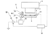
図3は、プリンター1の側面構造における断面を示す図である。図3に示されるように、紙送り機構8は、主動ローラー81及び該主動ローラー81の動作により従動される従動ローラー82とで構成される一対のローラー部(当接部)80を備えており、主動ローラー81及び従動ローラー82の回転により記録紙6をプラテン5上に給送するようになっている。
FIG. 3 is a diagram illustrating a cross section of the side structure of the printer 1. As shown in FIG. 3, the paper feed mechanism 8 includes a pair of roller portions (contact portions) 80 including a
ところで、上述したようなプリンター1では、紙送り機構8による給送時に、主動ローラー81及び従動ローラー82と擦れ合った記録紙6が摩擦により表面が帯電してしまう。このように記録紙6の表面が帯電すると、記録紙6に付着している紙粉が大きな電荷を持ち、クーロン力の影響が大きくなり、ノズル24に引き寄せられて異物として付着するおそれがある。すると、ノズル24からインクを良好に噴射できなくないといった不具合が発生してしまう。
By the way, in the printer 1 as described above, when the paper feeding mechanism 8 feeds, the surface of the
これに対し、本実施形態に係るプリンター1は、後述するように記録紙6の帯電量を測定しつつ、帯電量が所定の閾値を超えたときに、記録紙6の帯電量を低下させる処理を行うようにしている。
In contrast, the printer 1 according to the present embodiment measures the charge amount of the
具体的に本実施形態に係るプリンター1は、上記記録紙6の帯電量を検出する検出センサー(帯電量検出部)91と、上記ローラー部80を除電するための除電機構90と、を備えている。検出センサー91は、例えば静電気検出センサーを用いた。
Specifically, the printer 1 according to the present embodiment includes a detection sensor (charge amount detection unit) 91 that detects the charge amount of the
除電機構90は、主動ローラー81及び従動ローラー82に電気的に接続される導電部92と、導電部92に接続される配線部93と、配線部93の途中に設けられるスイッチング回路部94と、を備えている。配線部93の一端側は接地されている。また、制御装置58はスイッチング回路部94と電気的に接続されており、スイッチング回路部94をON/OFFすることで配線部93を介してローラー部80を接地可能となっている。
The
図4は、上述したプリンター(液体噴射装置)の電気的な構成を示すブロック図である。
プリンター1は、プリンター1全体の動作を制御する制御装置58を備えている。この制御装置58には、プリンター1の動作に関する各種情報を入力する入力装置59と、プリンター1の動作に関する各種情報を記憶した記憶装置60とが接続されている。
FIG. 4 is a block diagram illustrating an electrical configuration of the above-described printer (liquid ejecting apparatus).
The printer 1 includes a
また、制御装置58には、キャリッジ移動機構7、紙送り機構8、キャッピング機構11等が電気的に接続されている。また、制御装置58には、圧電素子65に入力する駆動信号を発生する駆動信号発生器62が電気的に接続されている。さらに、制御装置58には、上記ローラー部80、検出センサー91、及び除電機構90が電気的に接続されている。プリンター1は、検出センサー91により記録紙6の表面の帯電量を測定しつつ、その測定結果を制御装置58に通信するようになっている。
Further, the
続いて、プリンター1の動作について図5に示すフローチャートを参考しつつ、説明する。まず、プリンター1は、紙送り機構8を駆動し、記録ヘッド2の下方に搬送した記録紙6に対し、ノズル24からインクを吐出する。このとき、検出センサー91は、紙送り機構8により搬送される記録紙6の表面の帯電量を検出する(ステップS1)。
Next, the operation of the printer 1 will be described with reference to the flowchart shown in FIG. First, the printer 1 drives the paper feed mechanism 8 to eject ink from the
制御装置58は、検出センサー91による計測結果を予めメモリー内に記憶されている第1〜第4の閾値A1〜A4と比較する(ステップS2)。第1の閾値A1は、例えば帯電量が2KVの場合に設定されている。また、第2〜第4の閾値A2〜A4は、第1の閾値A1に対して10%刻みで高い帯電量に設定されている。すなわち、第4の閾値A4は、第1の閾値A1によりも30%高い帯電量(2.6KV)に設定されている。
The
制御装置58は、検出センサー91が検出した帯電量の値が第1の閾値A1よりも小さい場合、記録ヘッド2の記録紙6に対する印刷動作を継続する(ステップS2)。
When the charge amount detected by the
一方、制御装置58は、検出センサー91が検出した帯電量の値が第1の閾値A1よりも大きい場合、以下の判定を行う(ステップS2)。制御装置58は、検出センサー91が検出した帯電量の値が第1の閾値A1よりも大きく第2の閾値A2よりも小さい(第1の閾値A1以上第2の閾値A2未満)と判定した場合、記録紙6に対して印字動作を行うキャリッジ4のガイドロッド9に対する往復位置を制御する第1の処理を行う(ステップS3、4)。
On the other hand, when the value of the charge amount detected by the
通常、記録紙6の帯電量が上述したように比較的小さい場合、キャリッジ4がガイドロッド9に沿って移動する際に記録ヘッド2と記録紙6との間に生じる気流により記録紙6に付着している紙粉が噴射面23に付着することが防止される。
Usually, when the charge amount of the
一方、記録ヘッド2を保持するキャリッジ4は印字動作を行う際、ガイドロッド9に沿って往復運動している。キャリッジ4に保持される記録ヘッド2は折り返し位置で一旦停止した後、反対方向に移動する。このように記録ヘッド2が停止したタイミングでは、上述した気流が発生していないため、紙粉がクーロン力によって噴射面23に付着するおそれがある。
On the other hand, the
これに対し、制御装置58は平面視した状態において記録紙6の端面にノズル24が重ならない位置で記録ヘッド2を折り返し動作させるようにガイドロッド9に沿ってキャリッジ4を往復させるようにしている。記録紙6の端面6aは破断面であることから紙粉の付着量が特に多いため、ノズル24に紙粉を付着させる可能性が極めて高いからである。
On the other hand, the
制御装置58は、図6(a)に示すように、記録ヘッド2と記録紙6とが平面的に重ならない位置で記録ヘッド2の折り返し動作を行うのが望ましい。このように記録ヘッド2と記録紙6とを完全に離間させた位置で記録ヘッド2の往復動作を行うことで、記録ヘッド2が往復動作時において一時的に停止した際にも紙粉がノズル24に付着するのを防止できる。
As shown in FIG. 6A, the
また、例えば記録紙6の一部の領域にインクを吐出する場合、記録ヘッド2を記録紙6と平面的に重ならない位置までキャリッジ4を移動させる必要は無い。キャリッジ4の移動範囲を大きくすると、印刷速度が遅くなってしまうからである。この場合、記録ヘッド2と記録紙6とが平面的に視て重なる位置でキャリッジ4を往復動作させる。このとき、制御装置58は、図6(b)に示すように、噴射面23に形成されたノズル列A,B,Cのノズル24と記録紙6の端面6aとが重ならない位置(端面6aがノズル列A,B,C間に配置される位置)で、記録ヘッド2の折り返し動作を行うようにしている。この構成によれば、記録ヘッド2が記録紙6に対して平面的に重なる位置で往復運動する場合においても、紙粉付着量の多い記録紙6の端面6aにノズル24が平面的に重ならないため、紙粉がノズル24に付着するのを防止できる。
For example, when ink is ejected to a partial area of the
検出センサー91が測定した記録紙6の帯電量が第2の閾値A2よりも大きくなると、上述のようにキャリッジ4の往復位置を制御しただけではノズル24への紙粉の付着を十分に防止することが難しい。そこで、制御装置58は、検出センサー91が検出した帯電量の値が第2の閾値A2よりも大きく第2の閾値A2よりも小さい(第2の閾値A2以上第3の閾値A3未満)と判定した場合、記録紙6を搬送する主動ローラー81の回転速度を相対的に低くするように紙送り機構8を制御する第2の処理を行う(ステップS5、6)。
When the charge amount of the
主動ローラー81の回転速度を相対的に低くするとは、検出センサー91による検出前の主動ローラー81の回転速度を低下させることを意味する。記録紙6は主に主動ローラー81との摩擦によって帯電する。記録紙6の帯電量は主動ローラー81の回転速度に応じて増加し、やがて一定値に収束する。
Reducing the rotation speed of the
第2の処理においては、制御装置58は、主動ローラー81の回転速度を例えば10%程度低下させることで記録紙6の帯電量を低下させている。なお、回転速度を低下させる割合は一例であり、主動ローラー81と記録紙6との摩擦係数等によって適宜最適なものを選択可能である。
In the second process, the
これにより、記録紙6の帯電量が低下し、記録紙6の表面に付着している紙粉の帯電量を低下させることができる。よって、紙粉がクーロン力によって噴射面23のノズル24に付着するのを防止できる。
As a result, the charge amount of the
また、検出センサー91が測定した記録紙6の帯電量が第3の閾値A3よりも大きくなると、上述のように主動ローラー81の回転速度を相対的に低下させるように制御しただけではノズル24への紙粉の付着を十分に防止することが難しい。そこで、制御装置58は、検出センサー91が検出した帯電量の値が第3の閾値A3よりも大きく第4の閾値A4よりも小さい(第3の閾値A3以上第4の閾値A4未満)と判定した場合、上記除電機構90を駆動し、主動ローラー81を除電する第3の処理を行う(ステップS7、8)。
Further, when the charge amount of the
具体的に、制御装置58はスイッチング回路部94をON状態とする。これにより、ローラー部80は接地された状態となる。よって、主動ローラー81及び従動ローラー82は、接地されるため、記録紙6の帯電量を増加させることがなくなる。また、ローラー部80に接触する記録紙6は、ローラー部80を介して除電される。したがって、記録紙6の帯電量が低下し、記録紙6の表面に付着している紙粉の帯電量を低下させることができる。よって、紙粉がクーロン力によって噴射面23のノズル24に付着することを防止できる。
Specifically, the
なお、除電機構90としては、ローラー部80を直接接地させる機構に代えて、ローラー部80に除電ブラシを接触させる構成を採用することもできる。図7は除電機構190の変形例に係る構成を示す図である。図7に示されるように、除電機構190は主動ローラー81及び従動ローラー82に当接する除電ブラシ(接地ブラシ)95と、該除電ブラシ95を主動ローラー81及び従動ローラー82に対して接触或いは離間可能に駆動する駆動部96と、を備えている。また、駆動部96は制御装置58に電気的に接続されており、その駆動が制御されている。除電ブラシ95は導電性を有する樹脂性材料から構成され、且つ接地されたものとなっている。
In addition, as the
このような除電機構190を駆動する場合、制御装置58は駆動部96を駆動し、除電ブラシ95をローラー部80に接触させる。これにより、ローラー部80を接地した状態とすることができ、上述した場合と同様、記録紙6を除電することで紙粉がクーロン力によって噴射面23のノズル24に付着するのを防止できる。
When driving such a
ところで、記録紙6の帯電量が第4の閾値A4よりも大きくなると、記録紙6の表面に付着する紙粉がノズル24に引き寄せられる可能性が極めて高くなる。そこで、制御装置58は、検出センサー91が測定した記録紙6の帯電量が第4の閾値A4よりも大きい場合、上記第1〜第3の処理を全て同時に行う第4の処理を実行する(ステップS9)。
このように第1〜第3の処理を同時に行うことで記録紙6の帯電量を短時間で確実に低下させることができ、ノズル24に紙粉が付着するのを防止できる。
By the way, when the charge amount of the
By simultaneously performing the first to third processes in this way, the charge amount of the
上記第1〜第4の処理を行った後、記録紙6に対する一連の印字処理が終了したか否かについて判定する(ステップS10)。印刷処理が終了していない場合(Noの場合)、制御装置58はステップS1に戻り、検出センサー91が計測した記録紙6の帯電量を第1〜4の閾値A1〜A4と比較しつつ、判定の結果に応じて上述の処理を行う。一方、印刷処理が終了している場合(Yesの場合)、制御装置58は検出センサー91の動作を停止し、プリンター1の駆動を停止する。
After performing the first to fourth processes, it is determined whether or not a series of printing processes for the
以上述べたように、本実施形態に係るプリンター1によれば、紙送り機構8により搬送される記録紙6の帯電量が所定の値(第1〜第4の閾値)を超えた場合において、上述したように帯電量に応じて、適宜最適な第1〜第4の処理を実行することで帯電した紙粉が異物としてノズル24に付着することを防止できる。
したがって、紙粉がノズル24に付着することによるインク噴射不良の発生を防止することができる。
As described above, according to the printer 1 according to the present embodiment, when the charge amount of the
Therefore, it is possible to prevent the occurrence of defective ink ejection due to the paper dust adhering to the
上述の実施形態においては、記録紙6の帯電量に応じて第1〜第4の処理を実行したが、いずれか1つの処理だけでもよい。また、いずれか2つや3つの処理でもよい。
また、上述の実施形態においては、液体噴射装置がインクジェットプリンタである場合を例にして説明したが、インクジェットプリンタに限られず、複写機及びファクシミリ等の記録装置であってもよい。
In the above-described embodiment, the first to fourth processes are executed according to the charge amount of the
In the above-described embodiment, the case where the liquid ejecting apparatus is an ink jet printer has been described as an example. However, the liquid ejecting apparatus is not limited to the ink jet printer, and may be a recording apparatus such as a copying machine or a facsimile.
また、上述の各実施形態においては、液体噴射装置が、インク等の液体(液状体)を噴射する場合を例にして説明したが、本発明は、インク以外の他の流体を噴射したり吐出したりする液体噴射装置に適用することができる。液体噴射装置が噴射可能な流体は、液体、機能材料の粒子が分散又は溶解されている液状体、ジェル状の流状体、流体として流して噴射できる固体、及び粉体(トナー等)を含む。 In each of the above embodiments, the case where the liquid ejecting apparatus ejects a liquid (liquid material) such as ink has been described as an example. However, the present invention ejects or discharges fluid other than ink. The present invention can be applied to a liquid ejecting apparatus. Fluids that can be ejected by the liquid ejecting apparatus include liquids, liquids in which particles of functional materials are dispersed or dissolved, gel-like fluids, solids that can be ejected as fluids, and powders (toners, etc.) .
また、本発明は上述のように記録ヘッド2の噴射面23を除電することができるため、埃やインク噴射時に発生するミストが噴射面に23に付着することでインクの噴射不良が発生することを防止できる。したがって、紙粉の付着が問題とならないような紙粉を発生しない記録媒体、例えばフィルムや液晶ディスプレイ、EL(エレクトロルミネッセンス)ディスプレイ、及び面発光ディスプレイ(FED)の製造等に用いられる電極材、色材等の材料を所定の分散媒(溶媒)に分散(溶解)した液体(液状体)を噴射する液体噴射装置に適用可能である。
In addition, since the present invention can neutralize the
1…プリンター(液体噴射装置)、2…記録ヘッド(液体噴射ヘッド)、4…キャリッジ、6…記録紙(記録媒体)、6a…端面、8…紙送り機構(搬送装置)、9…ガイドロッド(ガイド部)、23…噴射面(ノズル面)、24…ノズル、58…制御装置(駆動制御部)、80…ローラー部(当接部)、81…主動ローラー、82…従動ローラー、90,190…除電機構、91…検出センサー(帯電量検出部)、95…除電ブラシ(接地ブラシ)、96…駆動部、A1〜A3…ノズル列
DESCRIPTION OF SYMBOLS 1 ... Printer (liquid ejecting apparatus), 2 ... Recording head (liquid ejecting head), 4 ... Carriage, 6 ... Recording paper (recording medium), 6a ... End surface, 8 ... Paper feed mechanism (conveyance apparatus), 9 ... Guide rod (Guide part), 23 ... Ejection surface (nozzle surface), 24 ... Nozzle, 58 ... Control device (drive control part), 80 ... Roller part (contact part), 81 ... Master drive roller, 82 ... Driven roller, 90, DESCRIPTION OF
Claims (7)
前記搬送装置により搬送される前記記録媒体にノズルから液体を噴射する液体噴射ヘッドと、
前記記録媒体の帯電量を検出する帯電量検出部と、
前記帯電量検出部により検出された前記帯電量が所定の値を超えたとき、
前記記録媒体の搬送速度を前記帯電量が前記所定の値より小さいときの搬送速度より低くするように前記搬送装置を制御すること、
或いは前記搬送装置における前記記録媒体に当接する当接部を除電する除電機構を駆動することの少なくともいずれかを行う駆動制御部と、を備えることを特徴とする液体噴射装置。 A transport device for transporting the recording medium;
A liquid ejecting head that ejects liquid from nozzles onto the recording medium transported by the transport device;
A charge amount detection unit for detecting the charge amount of the recording medium;
When the charge amount detected by the charge amount detection unit exceeds a predetermined value,
Controlling the transport device so that the transport speed of the recording medium is lower than the transport speed when the charge amount is smaller than the predetermined value ;
Alternatively, a liquid ejecting apparatus comprising: a drive control unit configured to drive at least one of a neutralization mechanism that neutralizes a contact portion that contacts the recording medium in the transport device.
前記帯電量検出部により検出された前記帯電量が所定の値を超えたとき、
前記駆動制御部が、平面視した状態において前記記録媒体の端面に前記ノズルが重ならない位置で前記液体噴射ヘッドを折り返し動作させるように前記ガイド部に沿って前記キャリッジを往復させることを特徴とする請求項1に記載の液体噴射装置。 A carriage that holds the liquid ejecting head so as to reciprocate along the guide portion;
When the charge amount detected by the charge amount detection unit exceeds a predetermined value,
The drive control unit reciprocates the carriage along the guide unit so that the liquid ejecting head is folded back at a position where the nozzle does not overlap the end surface of the recording medium in a plan view. The liquid ejecting apparatus according to claim 1.
前記駆動制御部が、前記キャリッジを前記ガイド部に沿って往復させる場合において、平面視した状態で、前記媒体の端面が前記複数のノズル列の間に位置させるように前記液体噴射ヘッドの折り返し動作を行うことを特徴とする請求項2に記載の液体噴射装置。 The liquid jet head has a nozzle surface including a plurality of nozzle rows in which a plurality of the nozzles are arranged,
When the drive control unit reciprocates the carriage along the guide unit, the liquid ejecting head is folded back so that the end surface of the medium is positioned between the plurality of nozzle rows in a plan view. The liquid ejecting apparatus according to claim 2 , wherein:
Priority Applications (3)
| Application Number | Priority Date | Filing Date | Title |
|---|---|---|---|
| JP2010031700A JP5418279B2 (en) | 2010-02-16 | 2010-02-16 | Liquid ejector |
| CN201110035478.4A CN102189770B (en) | 2010-02-16 | 2011-01-31 | Liquid injection apparatus |
| US13/028,080 US8556365B2 (en) | 2010-02-16 | 2011-02-15 | Liquid ejecting apparatus |
Applications Claiming Priority (1)
| Application Number | Priority Date | Filing Date | Title |
|---|---|---|---|
| JP2010031700A JP5418279B2 (en) | 2010-02-16 | 2010-02-16 | Liquid ejector |
Publications (3)
| Publication Number | Publication Date |
|---|---|
| JP2011167867A JP2011167867A (en) | 2011-09-01 |
| JP2011167867A5 JP2011167867A5 (en) | 2013-02-28 |
| JP5418279B2 true JP5418279B2 (en) | 2014-02-19 |
Family
ID=44369359
Family Applications (1)
| Application Number | Title | Priority Date | Filing Date |
|---|---|---|---|
| JP2010031700A Active JP5418279B2 (en) | 2010-02-16 | 2010-02-16 | Liquid ejector |
Country Status (3)
| Country | Link |
|---|---|
| US (1) | US8556365B2 (en) |
| JP (1) | JP5418279B2 (en) |
| CN (1) | CN102189770B (en) |
Families Citing this family (6)
| Publication number | Priority date | Publication date | Assignee | Title |
|---|---|---|---|---|
| JP5869314B2 (en) * | 2011-11-22 | 2016-02-24 | 株式会社Okiデータ・インフォテック | Inkjet recording apparatus and recording method |
| JP6225698B2 (en) * | 2013-12-26 | 2017-11-08 | セイコーエプソン株式会社 | Recording device |
| WO2015199642A1 (en) | 2014-06-23 | 2015-12-30 | Hewlett-Packard Development Company, L.P. | Printhead assembly |
| JP2016010865A (en) * | 2014-06-27 | 2016-01-21 | セイコーエプソン株式会社 | Recording device |
| JP7059532B2 (en) | 2017-07-26 | 2022-04-26 | セイコーエプソン株式会社 | Liquid discharge device |
| CN114603816A (en) * | 2022-03-25 | 2022-06-10 | 贺瑞峰 | Drip irrigation zone production traction assembly |
Family Cites Families (16)
| Publication number | Priority date | Publication date | Assignee | Title |
|---|---|---|---|---|
| JPH10193703A (en) * | 1997-01-08 | 1998-07-28 | Tec Corp | Ink jet printer |
| JP2000168191A (en) * | 1998-12-08 | 2000-06-20 | Fuji Photo Film Co Ltd | Image/data recording apparatus |
| JP2000289291A (en) * | 1999-04-06 | 2000-10-17 | Seiko Epson Corp | Recording apparatus |
| JP2002046310A (en) * | 2000-08-02 | 2002-02-12 | Noritsu Koki Co Ltd | Image forming apparatus |
| JP3552694B2 (en) * | 2000-10-17 | 2004-08-11 | セイコーエプソン株式会社 | Ink jet recording device |
| JP4022725B2 (en) * | 2002-01-31 | 2007-12-19 | リコープリンティングシステムズ株式会社 | Inkjet recording device |
| CN100429078C (en) * | 2002-10-03 | 2008-10-29 | 精工爱普生株式会社 | Printer and printing method |
| JP2004256299A (en) * | 2002-10-03 | 2004-09-16 | Seiko Epson Corp | Printer and printing method |
| JP4069794B2 (en) * | 2003-04-28 | 2008-04-02 | セイコーエプソン株式会社 | Recorded material transport device |
| JP4295663B2 (en) * | 2004-05-12 | 2009-07-15 | 株式会社リコー | Image forming apparatus |
| CN100496980C (en) * | 2004-06-02 | 2009-06-10 | 佳能株式会社 | Head substrate, recording head, head cartridge, and recorder |
| JP4890750B2 (en) * | 2004-07-30 | 2012-03-07 | 株式会社リコー | Image forming method and image forming apparatus |
| JP4848850B2 (en) * | 2006-06-14 | 2011-12-28 | パナソニック株式会社 | Inkjet image forming apparatus |
| JP2009007119A (en) * | 2007-06-28 | 2009-01-15 | Canon Inc | Image forming device |
| JP5239492B2 (en) * | 2008-05-08 | 2013-07-17 | セイコーエプソン株式会社 | Printing control method for serial ink jet printer and serial ink jet printer |
| JP2010137394A (en) * | 2008-12-10 | 2010-06-24 | Canon Inc | Inkjet recording apparatus |
-
2010
- 2010-02-16 JP JP2010031700A patent/JP5418279B2/en active Active
-
2011
- 2011-01-31 CN CN201110035478.4A patent/CN102189770B/en active Active
- 2011-02-15 US US13/028,080 patent/US8556365B2/en active Active
Also Published As
| Publication number | Publication date |
|---|---|
| CN102189770A (en) | 2011-09-21 |
| CN102189770B (en) | 2015-08-05 |
| JP2011167867A (en) | 2011-09-01 |
| US20110199411A1 (en) | 2011-08-18 |
| US8556365B2 (en) | 2013-10-15 |
Similar Documents
| Publication | Publication Date | Title |
|---|---|---|
| JP5418279B2 (en) | Liquid ejector | |
| JP4563650B2 (en) | Paper conveying apparatus and image forming apparatus | |
| JP2010099880A (en) | Liquid discharge head and image forming apparatus | |
| JP5760700B2 (en) | Liquid ejector | |
| JP4602786B2 (en) | Image forming apparatus | |
| US20120287208A1 (en) | Liquid ejecting apparatus | |
| JP2011161652A (en) | Liquid jetting device | |
| JP5222759B2 (en) | Fluid ejection device and fluid ejection device cleaning method | |
| US20120218332A1 (en) | Liquid ejecting apparatus | |
| JP2011161653A (en) | Liquid jetting device | |
| JP2007144673A (en) | Recorder | |
| JP2009012370A (en) | Fluid jet apparatus and maintenance method of fluid jet apparatus | |
| JP2010201788A (en) | Fluid jetting apparatus and cleaning method for the same | |
| JP2012218200A (en) | Liquid ejecting apparatus, and method of controlling the same | |
| JP4218035B2 (en) | Liquid ejector | |
| JP6953817B2 (en) | Device that discharges liquid | |
| JP2006315218A (en) | Liquid ejection head and image forming apparatus | |
| JP2007069545A (en) | Liquid discharge head and image forming apparatus | |
| JP2007055192A (en) | Droplet delivery device | |
| JP4439015B2 (en) | Paper conveying apparatus and image forming apparatus | |
| JP5719398B2 (en) | Fluid ejection device | |
| JP2012236340A (en) | Liquid ejecting apparatus | |
| JP6429635B2 (en) | Inkjet recording device | |
| JP2012232543A (en) | Liquid ejection apparatus | |
| JP2010173324A (en) | Liquid jet device |
Legal Events
| Date | Code | Title | Description |
|---|---|---|---|
| RD04 | Notification of resignation of power of attorney |
Free format text: JAPANESE INTERMEDIATE CODE: A7424 Effective date: 20120202 |
|
| A521 | Written amendment |
Free format text: JAPANESE INTERMEDIATE CODE: A523 Effective date: 20130111 |
|
| A621 | Written request for application examination |
Free format text: JAPANESE INTERMEDIATE CODE: A621 Effective date: 20130111 |
|
| A977 | Report on retrieval |
Free format text: JAPANESE INTERMEDIATE CODE: A971007 Effective date: 20131011 |
|
| TRDD | Decision of grant or rejection written | ||
| A01 | Written decision to grant a patent or to grant a registration (utility model) |
Free format text: JAPANESE INTERMEDIATE CODE: A01 Effective date: 20131022 |
|
| A61 | First payment of annual fees (during grant procedure) |
Free format text: JAPANESE INTERMEDIATE CODE: A61 Effective date: 20131104 |
|
| R150 | Certificate of patent or registration of utility model |
Ref document number: 5418279 Country of ref document: JP Free format text: JAPANESE INTERMEDIATE CODE: R150 |
|
| S531 | Written request for registration of change of domicile |
Free format text: JAPANESE INTERMEDIATE CODE: R313531 |
|
| R350 | Written notification of registration of transfer |
Free format text: JAPANESE INTERMEDIATE CODE: R350 |