JP6728689B2 - Printer - Google Patents
Printer Download PDFInfo
- Publication number
- JP6728689B2 JP6728689B2 JP2016004161A JP2016004161A JP6728689B2 JP 6728689 B2 JP6728689 B2 JP 6728689B2 JP 2016004161 A JP2016004161 A JP 2016004161A JP 2016004161 A JP2016004161 A JP 2016004161A JP 6728689 B2 JP6728689 B2 JP 6728689B2
- Authority
- JP
- Japan
- Prior art keywords
- printing
- print medium
- static elimination
- paper
- determination
- Prior art date
- Legal status (The legal status is an assumption and is not a legal conclusion. Google has not performed a legal analysis and makes no representation as to the accuracy of the status listed.)
- Active
Links
Images


Landscapes
- Handling Of Sheets (AREA)
- Accessory Devices And Overall Control Thereof (AREA)
- Dot-Matrix Printers And Others (AREA)
- Feeding Of Articles By Means Other Than Belts Or Rollers (AREA)
- Ink Jet (AREA)
Description
本発明は、搬送ベルトに静電吸着されている印刷媒体に印刷を施す印刷装置に関する。 The present invention relates to a printing apparatus that prints on a print medium that is electrostatically attracted to a conveyor belt.
特許文献1には、搬送ベルトと、印刷媒体に向けてインクなどの印刷材を吐出する印刷ヘッドとを備える印刷装置の一例が記載されている。こうした印刷装置では、帯電部によって搬送ベルトが帯電されると、同搬送ベルト上に給送された印刷媒体が同搬送ベルトに静電吸着される。そして、搬送ベルトの稼働によって印刷媒体が搬送されると、同印刷媒体の両面のうち、同搬送ベルトに接触していない面である印刷面に、印刷ヘッドからの印刷材が付着される。
ところで、搬送ベルトによる印刷媒体の静電吸着の効率を高めるためには、印刷媒体の印刷面から電荷を除去することが望ましい。そこで、こうした印刷装置には、印刷媒体の印刷面に接触することにより、同印刷面から電荷を除去する除電部が設けられていることもある。 By the way, in order to increase the efficiency of electrostatic attraction of the print medium by the transport belt, it is desirable to remove the charge from the print surface of the print medium. Therefore, such a printing apparatus may be provided with a charge removing unit that removes electric charges from the printing surface of the printing medium by contacting the printing surface of the printing medium.
しかしながら、この場合、印刷媒体の印刷面から電荷を除去するために、除電部を印刷媒体に接触させることとなるため、同除電部が徐々に劣化することとなる。そして、このように除電部の劣化が進むと、同除電部による印刷媒体からの電荷の除去効率が低下してしまう。 However, in this case, in order to remove the electric charge from the printing surface of the print medium, the charge eliminating portion is brought into contact with the print medium, so that the charge eliminating portion is gradually deteriorated. Then, when the deterioration of the charge eliminating portion progresses in this way, the efficiency of removing the charge from the print medium by the charge eliminating portion decreases.
本発明の目的は、除電部による印刷媒体からの電荷の除去効率の低下を抑制することができる印刷装置を提供することにある。 An object of the present invention is to provide a printing apparatus capable of suppressing a decrease in efficiency of removing charges from a print medium by a charge removing unit.
上記目的を達成するための印刷装置は、印刷媒体を搬送する搬送ベルトと、前記搬送ベルトに電荷を供給する帯電部と、印刷媒体の両面のうち前記搬送ベルトに接触している面を接触面とし、前記接触面の反対側の面を印刷面とした場合、前記搬送ベルトに静電吸着されている印刷媒体の前記印刷面に印刷材を付着させる印刷ヘッドと、前記搬送ベルトによって搬送されている印刷媒体に接触可能な位置である除電位置と前記印刷媒体に接触不能な位置である退避位置との間で変位可能であるとともに、前記印刷媒体の前記印刷面に接触することにより前記印刷面から電荷を除去する除電部と、前記除電部の位置を制御する除電制御装置と、を備え、前記除電制御装置は、前記搬送ベルトに静電吸着されて搬送される前記印刷媒体が前記除電部と接触可能な位置にあるとき、前記除電部を前記除電位置に配置する。 A printing apparatus for achieving the above object is a conveyor belt that conveys a printing medium, a charging unit that supplies an electric charge to the conveyor belt, and a surface of the both sides of the printing medium that is in contact with the conveyor belt. When the surface opposite to the contact surface is the printing surface, a print head that attaches a printing material to the printing surface of the print medium electrostatically attracted to the transport belt, and a print head that is transported by the transport belt The print surface that is displaceable between a static elimination position that is a position that can contact the print medium and a retracted position that is a position that cannot contact the print medium, and that is in contact with the print surface of the print medium. A static eliminator that removes electric charges from the static eliminator, and a static eliminator control device that controls the position of the static eliminator. The static eliminator is disposed at the static eliminator position when the static eliminator is in a position capable of contacting with.
上記構成によれば、印刷媒体への印刷に際し、搬送ベルトによって搬送されている印刷媒体に除電部を接触させること、及び、同印刷媒体に除電部を接触させないことを選択することができる。そのため、除電部が除電位置に常時配置されている場合と比較し、除電部が印刷媒体や搬送ベルトに接触する機会を減らすことができる分、除電部の劣化が遅くなる。そして、このように除電部の劣化を遅らせることにより、除電部による印刷媒体からの電荷の除去効率の低下を抑制することができるようになる。 According to the above configuration, when printing on the print medium, it is possible to select whether the charge eliminating unit is brought into contact with the print medium being conveyed by the convey belt, or not being brought into contact with the print medium. Therefore, as compared with the case where the static eliminator is always arranged at the static eliminator position, the chance of the static eliminator coming into contact with the print medium or the transport belt can be reduced, and the deterioration of the static eliminator is delayed. Then, by delaying the deterioration of the charge eliminating unit in this manner, it becomes possible to suppress a decrease in the efficiency of removing charges from the print medium by the charge eliminating unit.
上記印刷装置において、前記除電制御装置は、印刷対象となる印刷媒体の種類に応じ、前記搬送ベルトによって搬送されている印刷媒体に前記除電部を接触させるか否かを判定し、前記判定結果に基づいて前記除電部の位置を制御することが好ましい。 In the printing device, the static elimination control device determines whether to contact the static elimination unit with the print medium being conveyed by the conveyor belt according to the type of the print medium to be printed, and the determination result It is preferable to control the position of the static eliminator based on the above.
印刷媒体の種類を特定することにより、印刷材の付着によってカールの発生しやすい印刷媒体であるか否か、抵抗値が高い印刷媒体であるか否かなどを判断することが可能となる。そして、カールが発生しやすい印刷媒体であるとき、又は、抵抗値の高い印刷媒体であるときには、除電部によって印刷媒体の印刷面から電荷を除去することにより、搬送ベルトによる印刷媒体の静電吸着力を大きくすることが望ましい。その一方で、カールが発生しにくい印刷媒体であるとき、又は、抵抗値の低い印刷媒体であるときには、搬送ベルトによる印刷媒体の静電吸着力をそれほど高くしなくてもよい。そこで、上記構成では、印刷対象となる印刷媒体の種類に応じて除電部を除電位置に配置するか退避位置に配置するかを判定し、同判定結果に基づいて除電部の位置を制御するようにした。これにより、搬送ベルトによる印刷媒体の静電吸着力を大きくしなくてもよいと判断できるときには印刷媒体と除電部との接触を回避することができる。そのため、印刷対象となる印刷媒体の種類によっては印刷時に除電部を退避位置に配置することができるため、除電部が除電位置に常時配置されている場合と比較し、除電部が劣化しにくくなる。その結果、除電部による印刷媒体からの電荷の除去効率の低下を抑制することができる。 By specifying the type of the print medium, it is possible to determine whether or not the print medium is likely to curl due to the adhesion of the print material, or whether or not the print medium has a high resistance value. When the print medium is liable to curl or has a high resistance value, the charge removing unit removes electric charges from the print surface of the print medium to electrostatically adsorb the print medium by the conveyor belt. It is desirable to increase power. On the other hand, when the print medium does not easily curl or the print medium has a low resistance value, the electrostatic attraction force of the transport belt on the print medium does not have to be so high. Therefore, in the above-described configuration, it is determined whether the static elimination unit is placed at the static elimination position or the retracted position according to the type of print medium to be printed, and the position of the static elimination unit is controlled based on the determination result. I chose This makes it possible to avoid contact between the print medium and the static eliminator when it can be determined that the electrostatic attraction force of the transport belt on the print medium does not have to be increased. Therefore, depending on the type of print medium to be printed, the static eliminator can be placed in the retracted position during printing, so the static eliminator is less likely to deteriorate as compared to the case where the static eliminator is always placed in the static eliminator. .. As a result, it is possible to suppress a decrease in efficiency of removing charges from the print medium by the charge removing unit.
上記印刷装置において、前記除電制御装置は、前記印刷装置の設置環境の湿度に基づき、前記搬送ベルトによって搬送されている印刷媒体に前記除電部を接触させるか否かを判定し、前記判定結果に基づいて前記除電部の位置を制御することが好ましい。 In the printing device, the static elimination control device determines, based on the humidity of the installation environment of the printing device, whether or not to make the static elimination portion contact the print medium being conveyed by the conveying belt, and to the determination result. It is preferable to control the position of the static eliminator based on the above.
印刷装置の設置環境の湿度が高いほど印刷媒体の抵抗値が低くなりやすい。そして、印刷媒体の抵抗値が低いときには、除電部によって印刷媒体の印刷面から電荷を除去しなくても、印刷面の電荷が自然に中和されやすくなる。すなわち、除電部によって印刷媒体の印刷面から電荷を除去しなくても、搬送ベルトによる印刷媒体の静電吸着力が大きくなる。そこで、上記構成では、印刷装置の設置環境の湿度を鑑みて除電部の位置を制御するようにしている。そのため、印刷装置の設置環境の湿度によっては印刷時に除電部を退避位置に配置することができる。その結果、除電部が除電位置に常時配置されている場合と比較し、除電部が劣化しにくくなり、除電部による印刷媒体からの電荷の除去効率の低下を抑制することができる。 The higher the humidity of the installation environment of the printing apparatus, the lower the resistance value of the printing medium is likely to be. Then, when the resistance value of the print medium is low, the charge on the print surface is easily neutralized naturally without removing the charge from the print surface of the print medium by the charge removing unit. That is, even if the charge removing unit does not remove the charges from the printing surface of the printing medium, the electrostatic attraction force of the printing medium by the conveyor belt increases. Therefore, in the above-described configuration, the position of the static eliminator is controlled in consideration of the humidity of the installation environment of the printing apparatus. Therefore, depending on the humidity of the installation environment of the printing apparatus, the static eliminator can be placed in the retracted position during printing. As a result, the static eliminator is less likely to deteriorate as compared with the case where the static eliminator is always arranged at the static eliminator position, and it is possible to suppress a decrease in efficiency of removing charges from the print medium by the static eliminator.
上記印刷装置は、前記印刷装置の設置環境の温度と湿度とに基づき、印刷対象となる印刷媒体の抵抗値が高くなっているか否かを判定する判定装置を備え、前記除電制御装置は、前記判定装置によって印刷媒体の抵抗値が高くなっていると判定されているときには前記除電部を前記除電位置に配置する一方、前記判定装置によって印刷媒体の抵抗値が低くなっていると判定されているときには前記除電部を前記退避位置に配置することが好ましい。 The printing device, based on the temperature and humidity of the installation environment of the printing device, a determination device for determining whether the resistance value of the print medium to be printed is high, the static elimination control device, When the determination device determines that the resistance value of the print medium is high, the static elimination unit is arranged at the static elimination position, while the determination device determines that the resistance value of the print medium is low. It is sometimes preferable to dispose the static eliminator at the retracted position.
印刷装置の設置環境の温度及び湿度によって印刷媒体の抵抗値が変化する。そして、こうした設置環境の温度及び湿度と、印刷媒体の抵抗値との関係は実験やシミュレーションなどによってある程度把握することができる。すなわち、設置環境の温度及び湿度に基づいて印刷媒体の抵抗値を推定することができる。そこで、上記構成では、印刷装置の設置環境の温度及び湿度に基づいて印刷媒体の抵抗値が高くなっているか否かを判定し、同抵抗値が高くなっていると判定できるときには、搬送ベルトによって搬送されている印刷媒体に除電部を接触させるようにしている。反対に、印刷媒体の抵抗値が低くなっていると判定できるときには、搬送ベルトによって搬送されている印刷媒体に除電部を接触させないようにしている。すなわち、除電部によって印刷媒体の印刷面から電荷を除去しなくても同印刷面の電荷が自然に中和されやすいと予測できるときには、搬送ベルトによる印刷媒体の静電吸着力が比較的大きいため、除電部を印刷媒体に接触させない。そのため、印刷装置の設置環境の温度及び湿度とは関係なく除電部が除電位置に常時配置されている場合と比較し、除電部が劣化しにくくなる分、除電部による印刷媒体からの電荷の除去効率の低下を抑制することができる。 The resistance value of the print medium changes depending on the temperature and humidity of the installation environment of the printing apparatus. The relationship between the temperature and humidity of the installation environment and the resistance value of the print medium can be understood to some extent by experiments, simulations, and the like. That is, the resistance value of the print medium can be estimated based on the temperature and humidity of the installation environment. Therefore, in the above configuration, it is determined whether or not the resistance value of the print medium is high based on the temperature and humidity of the installation environment of the printing apparatus, and when it can be determined that the resistance value is high, the conveyance belt is used. The charge eliminating portion is brought into contact with the print medium being conveyed. On the other hand, when it can be determined that the resistance value of the print medium is low, the static eliminator is not brought into contact with the print medium conveyed by the conveyor belt. That is, when it can be predicted that the charge on the print surface of the print medium is likely to be neutralized naturally without removing the charge from the print surface of the print medium by the static eliminator, the electrostatic attraction force of the print medium by the conveyor belt is relatively large. , Do not let the static eliminator contact the print medium. Therefore, compared to the case where the static elimination unit is always placed in the static elimination position regardless of the temperature and humidity of the installation environment of the printing device, the static elimination unit is less likely to deteriorate, and the static elimination unit removes the charge from the print medium. It is possible to suppress a decrease in efficiency.
上記印刷装置は、印刷媒体の両面のうち第1の面への印刷が終了した後に、前記第1の面が前記接触面となるとともに前記第1の面の反対側の面である第2の面が前記印刷面となるように、前記印刷媒体の表裏を反転させて前記印刷媒体を前記搬送ベルト上に導く反転機構を備え、前記印刷ヘッドは、前記除電位置よりも搬送方向下流に配置されており、前記除電制御装置は、前記反転機構から前記搬送ベルト上に導かれた印刷媒体の前記第2の面に対して印刷を施すときには前記除電部を前記除電位置に配置することが好ましい。 In the printing apparatus, after printing on the first surface of both surfaces of the print medium is completed, the first surface serves as the contact surface and a second surface that is an opposite surface of the first surface. A reversing mechanism that reverses the front and back of the print medium and guides the print medium onto the transport belt so that the surface becomes the print surface, and the print head is disposed downstream of the charge removal position in the transport direction. Therefore, it is preferable that the static elimination control device disposes the static elimination unit at the static elimination position when performing printing on the second surface of the print medium guided onto the conveyor belt from the reversing mechanism.
印刷媒体に両面印刷を行う際、第1の面への印刷によって印刷材が付着している状況下で第2の面への印刷を行うときに搬送ベルト上で印刷媒体にカールが発生しやすい。そこで、上記構成では、反転機構から搬送ベルト上に導かれた印刷媒体の第2の面に印刷を行うときには、除電部を除電位置に配置し、除電部によって印刷媒体の第2の面から電荷を除去するようにしている。このように第2の面から電荷を除去することにより、搬送ベルトによる印刷媒体の静電吸着力を大きくすることができ、ひいては搬送ベルト上で印刷媒体がカールしにくくなる。その結果、印刷媒体が印刷ヘッドなどに接触する事象が発生しにくくなる分、印刷不良の発生を抑制することができる。 When performing double-sided printing on the print medium, the print medium is likely to curl on the conveyor belt when printing on the second surface under the condition that the print material is attached by printing on the first surface. .. Therefore, in the above configuration, when performing printing on the second surface of the print medium guided from the reversing mechanism onto the conveyor belt, the charge eliminating portion is arranged at the charge eliminating position, and the charge eliminating portion charges from the second surface of the print medium. Are being removed. By removing the charges from the second surface in this manner, the electrostatic attraction force of the print medium by the transport belt can be increased, and the print medium is less likely to curl on the transport belt. As a result, the occurrence of a printing failure can be suppressed because the occurrence of an event in which the print medium comes into contact with the print head is less likely to occur.
上記印刷装置は、印刷媒体の両面のうち第1の面への印刷が終了した後に、前記第1の面が前記接触面となるとともに前記第1の面の反対側の面である第2の面が前記印刷面となるように、前記印刷媒体の表裏を反転させて前記印刷媒体を前記搬送ベルト上に導く反転機構を備え、前記除電制御装置は、印刷媒体の前記第1の面への印刷によって前記印刷媒体がカールするか否かを判定し、印刷媒体の前記第1の面への印刷によって前記印刷媒体がカールすると判定しているときには、前記印刷媒体の前記第2の面への印刷に際して前記除電部を前記除電位置に配置する一方、印刷媒体の前記第1の面への印刷によって前記印刷媒体がカールしないと判定しているときには、前記印刷媒体の前記第2の面への印刷に際して前記除電部を前記退避位置に配置することが好ましい。 In the printing apparatus, after printing on the first surface of both surfaces of the print medium is completed, the first surface serves as the contact surface and a second surface that is an opposite surface of the first surface. The charge removal control device includes a reversing mechanism that reverses the front and back of the print medium and guides the print medium onto the conveyor belt so that the surface becomes the print surface. When it is determined whether the print medium is curled by printing, and when it is determined that the print medium is curled by printing on the first surface of the print medium, the print medium is printed on the second surface of the print medium. When it is determined that the print medium does not curl due to the printing on the first surface of the print medium while the charge removing unit is arranged at the charge removal position during printing, the print medium is transferred to the second surface of the print medium. At the time of printing, it is preferable to dispose the static eliminator at the retracted position.
上記構成によれば、第1の面に印刷を行っても印刷媒体がカールしないと判定している場合、第2の面への印刷時に除電部が印刷媒体に接触されない。そのため、第1の面への印刷態様によらず、第2の面への印刷時には除電部が除電位置に常時配置される場合と比較し、除電部が劣化しにくくなる分、除電部による印刷媒体からの電荷の除去効率の低下を抑制することができる。 According to the above configuration, when it is determined that the print medium does not curl even when printing is performed on the first surface, the charge eliminating unit does not contact the print medium when printing on the second surface. Therefore, regardless of the printing mode on the first surface, compared to the case where the static elimination unit is always placed at the static elimination position during printing on the second surface, the static elimination unit is less likely to deteriorate, and thus printing by the static elimination unit is performed. It is possible to suppress a decrease in the efficiency of removing charges from the medium.
上記印刷装置は、印刷媒体の両面のうち第1の面への印刷が終了した後に、前記第1の面が前記接触面となるとともに前記第1の面の反対側の面である第2の面が前記印刷面となるように、前記印刷媒体の表裏を反転させて前記印刷媒体を前記搬送ベルト上に導く反転機構を備え、印刷媒体は、4つの側辺を有するとともに、2つの前記側辺の接続部分である角を有しており、印刷媒体の前記第1の面を複数の領域に分割し、前記各領域のうち前記印刷媒体の角を含む領域を判定領域とした場合、前記除電制御装置は、前記印刷ヘッドから前記判定領域への印刷材の吐出によって前記判定領域に付着させることのできる印刷材の最大量である最大吐出量を算出し、印刷媒体の前記第1の面への印刷に採用される印刷データに基づき、前記印刷ヘッドから前記判定領域に吐出される印刷材の量である吐出量を算出し、前記吐出量の前記最大吐出量に対する割合である吐出割合を算出し、前記判定領域で前記吐出割合が判定割合未満となるときには、前記印刷媒体の前記第2の面への印刷に際して前記除電部を前記退避位置に配置する一方、前記判定領域で前記吐出割合が前記判定割合以上となるときには、前記印刷媒体の前記第2の面への印刷に際して前記除電部を前記除電位置に配置することが好ましい。 In the printing apparatus, after printing on the first surface of both surfaces of the print medium is completed, the first surface serves as the contact surface and a second surface that is an opposite surface of the first surface. A reversing mechanism that reverses the front and back of the print medium and guides the print medium onto the conveyor belt so that the surface becomes the print surface, and the print medium has four side edges and the two side portions. When the first surface of the print medium is divided into a plurality of areas and the area including the corners of the print medium is the determination area, The static elimination control device calculates the maximum discharge amount, which is the maximum amount of the printing material that can be attached to the determination area by discharging the printing material from the print head to the determination area, and the first surface of the print medium is calculated. Based on the print data used for printing on the print head, the discharge amount that is the amount of the printing material discharged from the print head to the determination area is calculated, and the discharge ratio that is the ratio of the discharge amount to the maximum discharge amount is calculated. When the discharge rate is less than the determination rate in the determination area, the static eliminator is placed in the retracted position when printing on the second surface of the print medium, while the discharge rate is in the determination area. Is greater than or equal to the determination ratio, it is preferable to dispose the static elimination unit at the static elimination position when printing on the second surface of the print medium.
第1の面への印刷によって印刷媒体の角を含む領域に付着する印刷材の量が多いほど、印刷媒体がカールしやすい。そこで、上記構成では、第1の面を分割した複数の領域のうち、印刷媒体の角を含む領域を判定領域とし、この判定領域の上記吐出割合が判定割合以上であるときには、第1の面への印刷によって印刷媒体がカールする可能性があると判定できるため、除電部を印刷媒体に接触させて搬送ベルトによる印刷媒体の静電吸着力を大きくした上で、第2の面への印刷を行っている。そのため、第2の面への印刷に際して印刷媒体が印刷ヘッドなどに接触する事象が生じにくくなる分、印刷不良の発生を抑制することができる。一方、判定領域の上記吐出割合が判定割合未満であるときには、第1の面への印刷によって印刷媒体がカールしないと判定できるため、除電部を印刷媒体に接触させないで、第2の面への印刷を行っている。このように除電部が印刷媒体に接触する機会を減らすことができる分、除電部の劣化が抑制され、除電部による印刷媒体からの電荷の除去効率の低下を抑制することができる。 The larger the amount of the printing material that adheres to the area including the corners of the printing medium due to the printing on the first surface, the more easily the printing medium curls. Therefore, in the above configuration, of the plurality of areas obtained by dividing the first surface, the area including the corner of the print medium is set as the determination area, and when the ejection ratio of the determination area is equal to or higher than the determination ratio, the first surface is determined. Since it can be determined that the print medium may curl when printed on the second surface, the charge removal unit is brought into contact with the print medium to increase the electrostatic attraction force of the print medium by the transport belt, and then the second surface is printed. It is carried out. Therefore, when printing on the second surface, it is less likely that the print medium will come into contact with the print head or the like, so that it is possible to suppress the occurrence of print defects. On the other hand, when the ejection ratio in the determination area is less than the determination ratio, it can be determined that the print medium does not curl due to the printing on the first surface. Printing. As described above, since it is possible to reduce the chances of the charge removing unit coming into contact with the print medium, it is possible to suppress deterioration of the charge removing unit, and it is possible to suppress a decrease in efficiency of removing charges from the print medium by the charge removing unit.
上記印刷装置は、印刷媒体の両面のうち第1の面への印刷が終了した後に、前記第1の面が前記接触面となるとともに前記第1の面の反対側の面である第2の面が前記印刷面となるように、前記印刷媒体の表裏を反転させて前記印刷媒体を前記搬送ベルト上に導く反転機構を備え、印刷媒体は、4つの側辺を有するとともに、2つの前記側辺の接続部分である角を有しており、印刷媒体の前記第1の面を複数の領域に分割し、前記各領域のうち前記印刷媒体の角を含む領域である端部領域と前記端部領域に隣接する領域とで構成される領域を判定領域とした場合、前記除電制御装置は、前記印刷ヘッドから前記判定領域への印刷材の吐出によって前記判定領域に付着させることのできる印刷材の最大量である最大吐出量を算出し、印刷媒体の前記第1の面への印刷に採用される印刷データに基づき、前記印刷ヘッドから前記判定領域に吐出される印刷材の量である吐出量を算出し、前記吐出量の前記最大吐出量に対する割合である吐出割合を算出し、前記判定領域で前記吐出割合が判定割合未満となるときには、前記印刷媒体の前記第2の面への印刷に際して前記除電部を前記退避位置に配置する一方、前記判定領域で前記吐出割合が前記判定割合以上となるときには、前記印刷媒体の前記第2の面への印刷に際して前記除電部を前記除電位置に配置することが好ましい。 In the printing apparatus, after printing on the first surface of both surfaces of the print medium is completed, the first surface serves as the contact surface and a second surface that is an opposite surface of the first surface. A reversing mechanism that reverses the front and back of the print medium and guides the print medium onto the conveyor belt so that the surface becomes the print surface, and the print medium has four side edges and the two side portions. An edge region that has a corner that is a connecting portion of a side, divides the first surface of the print medium into a plurality of regions, and includes an edge region that is a region including a corner of the print medium and the edge. When a region composed of a region adjacent to the partial region is set as the determination region, the static elimination control device is a printing material that can be attached to the determination region by discharging the printing material from the print head to the determination region. The maximum discharge amount that is the maximum amount of the print medium is calculated, and based on the print data used for printing on the first surface of the print medium, the discharge that is the amount of the print material discharged from the print head to the determination area. The amount is calculated, an ejection ratio, which is a ratio of the ejection amount to the maximum ejection amount, is calculated, and when the ejection ratio is less than the determination ratio in the determination region, printing on the second surface of the print medium is performed. At this time, the static eliminator is arranged at the retreat position, and when the ejection ratio is equal to or higher than the judgment ratio in the determination region, the static eliminator is moved to the static erasing position when printing on the second surface of the print medium. It is preferable to arrange them.
第1の面への印刷によって印刷媒体の角を含む領域に付着する印刷材の量が多いほど、印刷媒体がカールしやすい。そこで、上記構成では、第1の面を分割した複数の領域のうち、印刷媒体の角を含む端部領域と同端部領域に隣接する領域とで構成される領域が判定領域とされる。そして、この判定領域の上記吐出割合が判定割合以上であるときには、第1の面への印刷によって印刷媒体がカールする可能性があると判定できるため、除電部を印刷媒体に接触させて搬送ベルトによる印刷媒体の静電吸着力を大きくした上で、第2の面への印刷を行っている。そのため、第2の面への印刷に際して印刷媒体が印刷ヘッドなどに接触する事象が生じにくくなる分、印刷不良の発生を抑制することができる。一方、判定領域の上記吐出割合が判定割合未満であるときには、第1の面への印刷によって印刷媒体がカールしないと判定できるため、除電部を印刷媒体に接触させないで、第2の面への印刷を行っている。このように除電部が印刷媒体に接触する機会を減らすことができる分、除電部の劣化が抑制され、除電部による印刷媒体からの電荷の除去効率の低下を抑制することができる。 The larger the amount of the printing material that adheres to the area including the corners of the printing medium due to the printing on the first surface, the more easily the printing medium curls. Therefore, in the above configuration, of the plurality of areas obtained by dividing the first surface, an area including an edge area including the corner of the print medium and an area adjacent to the edge area is the determination area. When the ejection ratio in the determination area is equal to or higher than the determination ratio, it can be determined that the print medium may curl due to the printing on the first surface. The printing on the second surface is performed after the electrostatic attraction force of the print medium is increased. Therefore, when printing on the second surface, it is less likely that the print medium will come into contact with the print head or the like, so that it is possible to suppress the occurrence of print defects. On the other hand, when the ejection ratio in the determination area is less than the determination ratio, it can be determined that the print medium does not curl due to the printing on the first surface. Printing. As described above, since it is possible to reduce the chances of the charge removing unit coming into contact with the print medium, it is possible to suppress deterioration of the charge removing unit, and it is possible to suppress a decrease in efficiency of removing charges from the print medium by the charge removing unit.
上記印刷装置において、印刷媒体の前記第1の面には、1つの前記角を含む前記判定領域が複数設定されるようになっており、前記除電制御装置は、全ての前記判定領域で前記吐出割合が前記判定割合未満となるときには、前記印刷媒体の前記第2の面への印刷に際して前記除電部を前記退避位置に配置する一方、前記各判定領域のうち、少なくとも1つの前記判定領域で前記吐出割合が前記判定割合以上となるときには、前記印刷媒体の前記第2の面への印刷に際して前記除電部を前記除電位置に配置することが好ましい。 In the above printing apparatus, a plurality of the determination areas including one of the corners are set on the first surface of the print medium, and the static elimination control device is configured to perform the ejection in all the determination areas. When the ratio is less than the determination ratio, the static eliminator is arranged at the retracted position when printing on the second surface of the print medium, and at least one of the determination regions among the determination regions When the ejection rate is equal to or higher than the determination rate, it is preferable to dispose the static elimination unit at the static elimination position when printing on the second surface of the print medium.
上記構成によれば、判定領域毎に上記吐出割合が判定割合以上であるか否かを判定し、上記吐出割合が判定割合以上となる判定領域が1つでもあるときには、第1の面への印刷によって印刷媒体がカールする可能性があると判定できる。そのため、除電部を印刷媒体に接触させて搬送ベルトによる印刷媒体の静電吸着力を大きくした上で、第2の面への印刷を行っている。一方、上記吐出割合が判定割合以上となる判定領域が1つもないときには、第1の面への印刷によって印刷媒体がカールしないと判定できるため、除電部を印刷媒体に接触させないで、第2の面への印刷を行っている。このように除電部が印刷媒体に接触する機会を減らすことができる分、除電部の劣化が抑制され、除電部による印刷媒体からの電荷の除去効率の低下を抑制することができる。 According to the above configuration, it is determined whether or not the ejection ratio is equal to or higher than the determination ratio for each determination region, and when there is at least one determination region in which the ejection ratio is equal to or higher than the determination ratio, the first surface It can be determined that printing may curl the print medium. For this reason, the static elimination unit is brought into contact with the print medium to increase the electrostatic attraction force of the print medium by the conveyor belt, and then the second surface is printed. On the other hand, when there is no determination area in which the ejection ratio is equal to or higher than the determination ratio, it can be determined that the print medium does not curl due to the printing on the first surface. Printing on the surface. As described above, since it is possible to reduce the chances of the charge removing unit coming into contact with the print medium, it is possible to suppress deterioration of the charge removing unit, and it is possible to suppress a decrease in efficiency of removing charges from the print medium by the charge removing unit.
上記印刷装置において、前記除電部が前記除電位置にあって、前記搬送ベルトに静電吸着された前記印刷媒体に対する前記除電部の押圧力を変化可能な押圧力可変機構部を備え、前記除電制御装置は、前記押圧力可変機構部を用いて、前記吐出割合に応じて前記除電部の前記押圧力を変化させることが好ましい。 In the printing apparatus, the static eliminator is at the static eliminator position, and includes a pressing force variable mechanism unit capable of changing the pressing force of the static eliminator with respect to the print medium electrostatically attracted to the conveyor belt, and the static eliminator control It is preferable that the apparatus uses the pressing force variable mechanism unit to change the pressing force of the static elimination unit according to the discharge ratio.
吐出割合が高いと印刷媒体のカールの度合い、すなわち印刷媒体の湾曲した曲率が大きくなる可能性が高い。そこで、上記構成によれば、吐出割合が高いと除電部の押圧力を大きくさせることができるので、印刷媒体に除電部が接触する際の抵抗力を抑制するとともに、カールした形状の印刷媒体を伸ばし、印刷媒体における搬送ベルトとの接触面積を大きくすることができる。 When the ejection rate is high, the degree of curling of the print medium, that is, the curved curvature of the print medium is likely to increase. Therefore, according to the above configuration, when the discharge rate is high, the pressing force of the charge eliminating portion can be increased, so that the resistance force when the charge eliminating portion comes into contact with the print medium is suppressed and the curled shape of the print medium is reduced. By stretching, the contact area of the print medium with the conveyor belt can be increased.
上記印刷装置において、前記除電制御装置は、印刷媒体の前記第1の面に印刷を施すときには前記除電部を前記退避位置に配置することが好ましい。
第2の面への印刷時とは異なり、第1の面への印刷時には、印刷媒体に印刷材が未だ付着していないため、印刷媒体がカールしている可能性が低い。そこで、上記構成では、第1の面への印刷時にあっては、除電部を退避位置に配置し、除電部を印刷媒体に接触させないようにした。これにより、第1の面への印刷時でも除電部を除電位置に配置する場合と比較し、除電部が劣化しにくくなる分、除電部による印刷媒体からの電荷の除去効率の低下を抑制することができる。
In the above printing apparatus, it is preferable that the static elimination control device arranges the static elimination unit at the retracted position when performing printing on the first surface of the print medium.
Unlike the case of printing on the second side, the case of curling of the print medium is low at the time of printing on the first side because the print material has not yet adhered to the print medium. Therefore, in the above-described configuration, the charge eliminating unit is arranged at the retracted position during printing on the first surface so that the charge eliminating unit does not come into contact with the print medium. As a result, as compared with the case where the static elimination unit is arranged at the static elimination position even during printing on the first surface, the static elimination unit is less likely to deteriorate, and thus the reduction in efficiency of removing charges from the print medium by the static elimination unit is suppressed. be able to.
上記印刷装置は、前記除電位置よりも搬送方向上流に配置され、印刷媒体を前記搬送ベルトに押し付けるサポートローラーを備え、前記サポートローラーは、前記搬送ベルトの稼働によって従動回転することが好ましい。 It is preferable that the printing apparatus includes a support roller arranged upstream of the charge removal position in the transport direction and pressing a print medium against the transport belt, and the support roller is driven to rotate by the operation of the transport belt.
上記構成によれば、印刷媒体がサポートローラーによって搬送ベルトに押し付けられるため、印刷媒体と搬送ベルトとの密着度合いを高めることができる分、印刷媒体を適切に分極させることができる。その結果、搬送ベルトに印刷媒体を静電吸着させやすくすることができる。 According to the above configuration, since the print medium is pressed against the transport belt by the support roller, the degree of contact between the print medium and the transport belt can be increased, and thus the print medium can be appropriately polarized. As a result, the print medium can be easily electrostatically attracted to the transport belt.
上記印刷装置において、前記サポートローラーは、接地されていることが好ましい。
上記構成によれば、サポートローラーが接地されているため、印刷媒体の印刷面にサポートローラーが接触することにより、同印刷面からある程度電荷を除去することができる。
In the printing device, it is preferable that the support roller is grounded.
According to the above configuration, since the support roller is grounded, the support roller comes into contact with the print surface of the print medium, so that the charge can be removed to some extent from the print surface.
(第1の実施形態)
以下、印刷装置を、インクジェット式のプリンターに具体化した第1の実施形態を図1〜図6に従って説明する。
(First embodiment)
Hereinafter, a first embodiment in which the printing apparatus is embodied as an inkjet printer will be described with reference to FIGS. 1 to 6.
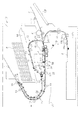
図1に示すように、本実施形態の印刷装置11の筐体12内には、印刷媒体の一例である用紙Pを媒体搬送路20に沿って搬送する搬送装置29と、搬送されている用紙Pに印刷を施す印刷ユニット14とが設けられている。図1において紙面と直交する方向を用紙の幅方向とした場合、媒体搬送路20は、用紙の幅方向と交差する方向、望ましくは幅方向と直交する方向に用紙Pを搬送するように形成されている。
As shown in FIG. 1, in the
印刷ユニット14は、用紙の幅方向の略全域に渡って印刷材の一例であるインクを同時に吐出可能なラインヘッド型の印刷ヘッド141を備えている。そして、この印刷ヘッド141から吐出されたインクが用紙Pに付着することにより、用紙Pに画像が形成される。
The
搬送装置29は、印刷済みとなった用紙Pを筐体12外に排出する排出機構部25と、印刷前の用紙Pを媒体搬送路20に沿って給送する給送機構部30とを備えている。
排出機構部25は、媒体搬送路20に沿って配置されている複数の排出ローラー対19を有している。この排出機構部25によって搬送される用紙Pは、筐体12に形成されている媒体排出口26から筐体12外に排出される。つまり、この媒体排出口26が、媒体搬送路20の下流端、すなわち媒体の搬送経路の最下流となっている。そして、媒体排出口26から排出された用紙Pは、図1に二点鎖線で示すように、載置台60上に積層状態で載置される。
The
The
給送機構部30は、第1の媒体供給部21と、第2の媒体供給部22と、第3の媒体供給部23と、静電搬送部50とを有している。静電搬送部50は、印刷ユニット14の図中直下に配置されている。すなわち、静電搬送部50によって搬送されている用紙Pに対し、印刷ヘッド141からインクが吐出される。
The
筐体12の一側面(図1では右側面)には開閉可能なカバー12Fが設けられており、このカバー12Fが開放されることにより挿入口12aが露出される。第1の媒体供給部21は、このように露出した挿入口12aから筐体12内に挿入された用紙Pを挟持する第1の給送ローラー対41を備えている。そして、この第1の給送ローラー対41を構成する2つのローラーの回転によって、用紙Pが静電搬送部50に向けて給送される。
An openable/
また、筐体12の図1における下部には、印刷前の用紙Pが積層状態でセットされる媒体カセット12cが設けられている。第2の媒体供給部22は、媒体カセット12cから用紙Pを給送するための供給部である。すなわち、第2の媒体供給部22は、媒体カセット12c内の最上位の用紙Pを媒体カセット12c外に送り出すピックアップローラー16aと、複数枚の用紙Pが重なって搬送されることを抑制する分離ローラー対16bと、分離ローラー対16bを通過した1枚の用紙Pを挟持する第2の給送ローラー対42とを備えている。そして、この第2の給送ローラー対42を構成する2つのローラーの回転によって、用紙Pが静電搬送部50に向けて給送される。
A
第3の媒体供給部23は、用紙Pに対して両側のシート面に印刷する両面印刷を行うときに、片側のシート面(第1の面)が印刷済みとなった用紙Pを、再び静電搬送部50に導くための供給部である。すなわち、静電搬送部50よりも用紙の搬送方向下流には、媒体搬送路20から分岐する分岐搬送路24が形成されている。そして、第3の媒体供給部23には、静電搬送部50よりも用紙の搬送方向下流に配置され、用紙Pの搬送経路を媒体搬送路20又は分岐搬送路24に切り替える分岐機構27と、分岐搬送路24に配置され、正逆両方向への回転が可能な分岐搬送路ローラー対44とが設けられている。
When performing double-sided printing in which the sheet surfaces on both sides are printed on the sheet P, the third
両面印刷を行う場合、片側のシート面が印刷済みとなった用紙Pは、静電搬送部50から分岐機構27によって分岐搬送路24に導かれる。このとき、分岐搬送路ローラー対44を構成する各ローラーの正方向への回転によって、用紙Pが搬送方向下流に搬送される。そして、用紙Pの後端が分岐搬送路24に導かれると、分岐搬送路ローラー対44を構成する各ローラーが逆方向に回転するようになり、用紙Pが逆方向に搬送されるようになる。すると、用紙Pは、図1において印刷ユニット14よりも上方に位置する反転供給路31に導かれる。そして、この反転供給路31上に配置されている複数の反転搬送ローラー対45の回転によって、用紙Pが反転供給路31に沿って給送される。これにより、用紙Pが、静電搬送部50よりも用紙の搬送方向上流で媒体搬送路20に合流される。その後、当該用紙Pが静電搬送部50に再び導かれる。
When double-sided printing is performed, the sheet P having one side sheet surface printed is guided from the
このように静電搬送部50に用紙Pが再び導かれると、印刷済みとなったシート面(第1の面)が静電搬送部50に接触し、印刷されていないシート面(第2の面)が印刷ヘッド141に対向することとなる。なお、用紙Pの両面のうち、静電搬送部50に接触するシート面のことを「接触面」といい、接触面の反対側の面を「印刷面」ということもある。すなわち、本実施形態の印刷装置11では、第3の媒体供給部23により、用紙Pの両面のうち第1の面への印刷が終了した後に、同第1の面が接触面となるとともに第2の面が印刷面となるように、用紙Pの表裏を反転させて同用紙Pを静電搬送部50に導く「反転機構」の一例が構成される。
When the sheet P is guided to the
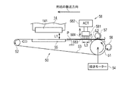
次に、図2A、図2Bを参照し、静電搬送部50とその周辺部材の構成について説明する。図2A、図2Bに示すように、静電搬送部50は、印刷ヘッド141よりも用紙の搬送方向上流(すなわち、図中右側)に配置されている搬送用駆動ローラー51と、印刷ヘッド141よりも用紙の搬送方向下流(すなわち、図中左側)に配置されている搬送用従動ローラー52とを備えている。また、これら各ローラー51,52に、無端状の搬送ベルト53が掛送されている。搬送用従動ローラー52は、図2Aに矢印で示すように、搬送用駆動ローラー51から離れる方向(図中左方)に付勢されている。そして、搬送モーター54の駆動が搬送用駆動ローラー51に伝達されることにより、搬送ベルト53が稼働され、用紙Pが搬送方向下流に搬送される。すなわち、搬送ベルト53の外面が、用紙Pの接触面に接触する支持面として機能することとなる。
Next, with reference to FIG. 2A and FIG. 2B, the configurations of the
また、印刷ヘッド141の直下には、搬送ベルト53を通じて用紙Pを支持する金属製のバックアッププレート55が設けられている。なお、バックアッププレート55は、接地されている。また、バックアッププレート55は、搬送ベルト53の支持面の反対側の面となる搬送ベルト53の内面に接触しているとともに、同搬送ベルト53を印刷ヘッド141側に付勢している。
A
また、搬送用駆動ローラー51よりも搬送方向上流(図中右側)には、帯電部の一例である帯電ローラー56が設けられている。この帯電ローラー56は、搬送ベルト53の外面に接触している。そして、搬送用駆動ローラー51の回転が搬送ベルト53を通じて帯電ローラー56に伝達されることにより、帯電ローラー56が搬送用駆動ローラー51に対して従動回転する。このとき、帯電ローラー56が搬送ベルト53の外面における接触箇所に電圧を印加することにより、搬送ベルト53における当該接触箇所が帯電される。すなわち、搬送ベルト53は、帯電ローラー56との接触によって帯電される。なお、本実施形態の印刷装置11では、帯電ローラー56は、接触している搬送ベルト53に対し、正の電荷と負の電荷とを交互に供給する。
Further, a charging
また、印刷ヘッド141よりも用紙の搬送方向上流(図中右側)には、静電搬送部50に給送された用紙Pを搬送ベルト53に押し付けるサポートローラー57が設けられている。このサポートローラー57は、例えば、金属などの導電材料で構成されており、接地されている。そして、搬送用駆動ローラー51の回転が搬送ベルト53を通じてサポートローラー57に伝達されることにより、サポートローラー57が搬送用駆動ローラー51に対して従動回転する。
A
さらに、用紙の搬送方向におけるサポートローラー57と印刷ヘッド141との間には、除電装置58が設けられている。この除電装置58は、ブラシ583などによって構成されている除電部581と、除電部581を変位させるアクチュエーター582とを備えている。この除電部581は、用紙の幅方向を主成分とする延出方向に延びており、用紙の幅方向における全域に接触可能である。そして、搬送ベルト53によって搬送されている用紙Pの印刷面に除電部581が接触すると、同除電部581が、同印刷面から電荷を除去するようになっている。
Further, a
また、除電部581は、アクチュエーター582の駆動によって、用紙Pに接触可能な位置である除電位置と、用紙Pに接触不能な位置である退避位置との間で変位可能となっている。すなわち、矢印に示すように、除電部581は用紙Pの印刷面に対して直交する方向に変位可能となっており、図2Aに示す除電部581の位置が除電位置であり、図2Bに示す除電部581の位置が退避位置である。
Further, the
本実施形態では、印刷ヘッド141からインクを吐出する方向(用紙Pの印刷面に対して直交する方向)において、印刷ヘッド141と搬送ベルト53との距離L1は、0.9mmである。
In the present embodiment, the distance L1 between the
図2Aの除電部581が除電位置にあって、ブラシ583が搬送ベルト53に吸着された用紙Pを押圧した状態では、用紙Pの印刷面に対して直交する方向において支持面584から用紙Pまでのブラシ583の距離L2は、5.5mmであり、搬送方向(図中左右方向)において、ブラシ583が搬送ベルト53と当接する範囲の距離L3は、8mmである。
2A is in the neutralization position and the
図2Bの除電部581が退避位置にあって、ブラシ583が搬送ベルト53から離れた状態では、用紙Pの印刷面に対して直交する方向において支持面584から立設するブラシ583の長さL4は、6.5mmである。
2B is in the retracted position and the
次に、図3A、図3Bを参照し、用紙Pが搬送ベルト53に静電吸着される際の作用について説明する。
図3Aに示すように、搬送用駆動ローラー51の回転によって搬送ベルト53が稼働されると、帯電ローラー56が従動回転することにより、搬送ベルト53の外面に正の電荷が帯電する部分である正部分71と、負の電荷が帯電する部分である負部分72とが交互に形成される。そして、こうした搬送ベルト53の外面にサポートローラー57によって用紙Pが押し付けられると、用紙Pが搬送ベルト53に密接し、同用紙P内で分極が発生する。すなわち、用紙Pの接触面Pa(図中下面)において搬送ベルト53の正部分71に対向する部分は、負の電荷が帯電する負部分73となる一方、用紙Pの接触面Paにおいて搬送ベルト53の負部分72に対向する部分は、正の電荷が帯電する正部分74となる。したがって、用紙Pの接触面Paにおいても、正部分74と負部分73とが交互に形成されるようになる。
Next, with reference to FIGS. 3A and 3B, the operation when the paper P is electrostatically attracted to the
As shown in FIG. 3A, when the
なお、接触面Paの反対側となる用紙Pの印刷面Pbでも、負の電荷が帯電する負部分75と、正の電荷が帯電する正部分76とが交互に形成されることとなる。そして、用紙Pの抵抗値が小さい場合、印刷面Pbに除電部581を接触させなくても、印刷面Pbでは、互いに隣り合う正部分76と負部分75とで電荷が自然に中和されやすい。そのため、図3Bに示すように、用紙Pが印刷ヘッド141の直下に達するまでに、印刷面Pbの電荷のほとんどが除去される。
Even on the printing surface Pb of the paper P, which is the opposite side of the contact surface Pa, the
しかし、用紙Pの抵抗値が高い場合、印刷面Pbでは、互いに隣り合う正部分76と負部分75とで電荷が自然に中和されにくい。この場合、印刷面Pb側の電荷と接触面Pa側の電荷とが互いに引き合うこととなる。印刷面Pb側の電荷と接触面Pa側の電荷との引き合いによって生じる力である引き合い力は、接触面Paを印刷面Pb側に引き寄せる力となる。すなわち、引き合い力は、用紙Pの接触面Paを搬送ベルト53に引き付ける力に対して斥力となる。そのため、搬送ベルト53に用紙Pを引き付ける力、すなわち静電吸着力が大きくなりにくい。したがって、このように用紙Pの抵抗値が大きいと予測される場合には、印刷面Pbに除電部581を接触させることにより、印刷面Pbから電荷のほとんどを除去することができる。これにより、上記の引き合い力が小さくなり、搬送ベルト53による用紙Pの静電吸着力が大きくなる。
However, when the resistance value of the paper P is high, on the printing surface Pb, it is difficult for the
ところで、除電部581が除電位置に配置されている場合、サポートローラー57及び帯電ローラー56とは異なり、搬送ベルト53の稼働に対して除電部581が従動回転されない。そのため、搬送ベルト53や用紙Pとの接触に起因する除電部581の劣化は、サポートローラー57及び帯電ローラー56よりも進行しやすい。そして、このように除電部581の劣化が進むにつれて、除電部581による用紙Pからの電荷の除去効率が低下される。
By the way, when the
ここで、印刷対象となる用紙Pの抵抗値が高いか否かは、用紙Pの種類、すなわち用紙の組成、用紙の重み、用紙の厚みなどから判断することができる。例えば、印刷装置11のユーザーインターフェイス、又は、印刷装置11と通信可能な外部装置(パーソナルコンピューターやモバイル端末)で、印刷対象となる用紙Pの種類を選択させ、その選択結果に応じた情報を制御装置で解析することにより、印刷対象となる用紙Pの抵抗値が高いか否かを判断することができる。
Here, whether or not the resistance value of the paper P to be printed is high can be determined from the type of the paper P, that is, the composition of the paper, the weight of the paper, the thickness of the paper, and the like. For example, the user interface of the
そこで、本実施形態の印刷装置11では、印刷対象の用紙Pの抵抗値が低いと判断できるときには、同用紙Pへの印刷に際して除電部581を退避位置に配置させる一方、印刷対象の用紙Pの抵抗値が高いと判断できるときには、同用紙Pへの印刷に際して除電部581を除電位置に配置させるようにした。
Therefore, in the
なお、同一種の用紙Pであっても、印刷装置11の設置環境などによって用紙Pの抵抗値が変化しうる。すなわち、印刷装置11の設置環境の温度TMPが一定である場合、設置環境の湿度HMDが高いほど用紙Pの抵抗値が低くなる。また、印刷装置11の設置環境の湿度HMDが一定である場合、設置環境の温度TMPが高いほど用紙Pの抵抗値が低くなる。
Even for the same type of paper P, the resistance value of the paper P may change depending on the installation environment of the
図4には、設置環境の温度TMPと湿度HMDとの関係に基づき、用紙Pの抵抗値が高くなっているか否かを判断するためのマップの一例が図示されている。図4に示すように、設置環境の温度TMPと湿度HMDとを示す点が、境界線L1よりも左下の領域である高抵抗領域A1に含まれる場合、用紙Pの抵抗値が高くなっていると判断することができる。一方、設置環境の温度TMPと湿度HMDとを示す点が、境界線L1よりも右上の領域である低抵抗領域A2に含まれる場合、用紙Pの抵抗値が低くなっていると判断することができる。 FIG. 4 illustrates an example of a map for determining whether or not the resistance value of the paper P is high based on the relationship between the temperature TMP of the installation environment and the humidity HMD. As shown in FIG. 4, when the points indicating the temperature TMP and the humidity HMD of the installation environment are included in the high resistance area A1 that is the lower left area of the boundary line L1, the resistance value of the paper P is high. Can be determined. On the other hand, when the point indicating the temperature TMP and the humidity HMD of the installation environment is included in the low resistance area A2 which is the area on the upper right of the boundary line L1, it may be determined that the resistance value of the paper P is low. it can.
そこで、本実施形態の印刷装置11では、設置環境の温度TMP及び湿度HMDに基づき、印刷対象の用紙Pの抵抗値が低くなっていると判断できるときには、同用紙Pへの印刷に際して除電部581を退避位置に配置させるようにした。一方、設置環境の温度TMP及び湿度HMDに基づき、印刷対象の用紙Pの抵抗値が高くなっていると判断できるときには、同用紙Pへの印刷に際して除電部581を除電位置に配置させるようにした。
Therefore, in the
ところで、インクの付着によって用紙Pにカールが発生すると、用紙Pが印刷ヘッド141などに接触し、用紙Pが汚れたり用紙Pがダメージを受けたりし、結果として、印刷不良が発生するおそれがある。そのため、カールが発生しやすい用紙Pへの印刷時にあっては、印刷不良の発生を抑制するという観点上、搬送ベルト53による用紙Pの静電吸着力が小さいことは望ましくない。その一方で、カールが発生しにくい用紙Pへの印刷時にあっては、搬送ベルト53による用紙Pの静電吸着力が小さくても、上記のような印刷不良が生じにくい。
When the paper P curls due to the adhesion of ink, the paper P comes into contact with the
なお、印刷対象となる用紙Pの種類によっては、用紙Pへのインクの付着によってカールの発生しやすさが相異する。言い換えると、用紙Pの種類を特定することにより、印刷対象の用紙Pのカールの発生しやすさを予測することができる。そこで、例えば、上記のように印刷対象となる用紙Pの種類をユーザーに選択させ、その選択結果に応じた情報を制御装置で解析することにより、印刷装置11で、今回の印刷対象の用紙Pでカールが発生しやすいか否かを判断することが可能となる。
Depending on the type of the paper P to be printed, the easiness of curling due to the adhesion of ink to the paper P differs. In other words, by specifying the type of paper P, it is possible to predict the likelihood of curling of the paper P to be printed. Therefore, for example, by causing the user to select the type of the paper P to be printed as described above and analyzing the information according to the selection result by the control device, the
そこで、本実施形態の印刷装置11では、印刷対象の用紙Pがインクの付着によってカールが発生しやすいと判断できるときには、同用紙Pへの印刷に際し、除電部581を除電位置に配置させるようにした。一方、印刷対象の用紙Pがインクの付着によってカールが発生しにくいと判断できるときには、同用紙Pへの印刷に際し、除電部581を退避位置に配置させるようにした。
Therefore, in the
次に、図5を参照し、印刷装置11の制御装置80について説明する。
図5に示すように、制御装置80には、印刷装置11の設置環境の温度TMPを検出する温度センサーSE1と、印刷装置11の設置環境の湿度HMDを検出する湿度センサーSE2と、ユーザーによって操作されるユーザーインターフェイス81とが電気的に接続されている。また、制御装置80には、パーソナルコンピューターやモバイル端末などの外部装置100と通信可能となっている。
Next, the
As shown in FIG. 5, the
こうした制御装置80は、CPU、ROM及びRAMなどで構成されるマイクロコンピューターと、ASIC(Application Specific IC(特定用途向けIC))と、各種のドライバー回路とを備えている。そして、制御装置80は、ソフトウェア及びハードウェアのうち少なくとも一方で構成される機能部として、入力情報処理部91、温湿度判定部92、用紙判定部93、除電制御部94、搬送制御部95及び印刷制御部96を含んでいる。
The
入力情報処理部91は、ユーザーインターフェイス81から入力された情報、及び、外部装置100から受信した情報を解析し、その解析結果を用紙判定部93、搬送制御部95及び印刷制御部96に適宜出力する。例えば、入力情報処理部91は、印刷対象となる用紙Pの種類に関する情報を用紙判定部93に出力し、用紙Pの搬送態様に関する情報を搬送制御部95に出力する。また、入力情報処理部91は、印刷精度に関する情報を印刷制御部96に出力する。
The input
なお、用紙Pの搬送態様に関する情報としては、例えば、用紙Pの搬送速度に関する情報、片面印刷又は両面印刷の何れかが選択されている旨の情報などを挙げることができる。また、印刷精度に関する情報としては、例えば、用紙Pに形成する画像に関するデータである印刷データ、及び、用紙Pの印刷面に形成する画像の解像度に関する情報を挙げることができる。 Note that examples of the information regarding the conveyance mode of the sheet P include information regarding the conveyance speed of the sheet P, information indicating that either one-sided printing or two-sided printing has been selected, and the like. Further, as the information regarding the printing accuracy, for example, print data that is data regarding an image formed on the paper P and information regarding the resolution of the image formed on the printing surface of the paper P can be cited.
温湿度判定部92は、温度センサーSE1によって検出されている温度TMPと、湿度センサーSE2によって検出されている湿度HMDとに基づき、用紙Pの抵抗値が高くなりやすい環境であるか否かを判定する。このとき、温湿度判定部92は、図4に示すマップを参照し、現時点の設置環境が高抵抗領域A1に含まれるか低抵抗領域A2に含まれるかを判定し、この判定結果に関する情報を除電制御部94に出力する。この点で、温湿度判定部92により、印刷装置11の設置環境の温度TMPと湿度HMDとに基づき、印刷対象となる用紙Pの抵抗値が高くなっているか否かを判定する「判定装置」の一例が構成される。
The temperature/
用紙判定部93は、入力情報処理部91から入力された情報に基づき、印刷対象となる用紙Pが抵抗値の高い用紙であるか否か、インクの付着によってカールが発生しやすい用紙であるか否かなどを判定する。そして、用紙判定部93は、判定結果に関する情報を除電制御部94に出力する。
Based on the information input from the input
除電制御部94は、用紙判定部93及び温湿度判定部92から入力された情報に基づき、除電部581を除電位置に配置させるか退避位置に配置させるかを判定する。すなわち、除電制御部94は、用紙Pへの印刷に際し、搬送ベルト53によって搬送されている用紙Pに除電部581を接触させるか否かを判定する。
The static
例えば、除電制御部94は、以下に示す3つの条件のうち少なくとも1つが成立しているときには、除電部581を除電位置に配置させる旨を決定する。一方、除電制御部94は、以下に示す全ての条件が成立していないときには、除電部581を退避位置に配置させる旨を決定する。
・用紙判定部93からの入力情報に基づき、印刷対象となる用紙Pの抵抗値が高いと判定した場合。
・用紙判定部93からの入力情報に基づき、印刷対象となる用紙Pがカールしやすい用紙であると判定した場合。
・温湿度判定部92からの入力情報に基づき、現時点での印刷装置11の設置環境が高抵抗領域A1に含まれている場合。
For example, the static
When it is determined that the resistance value of the paper P to be printed is high based on the input information from the
When it is determined that the paper P to be printed is a paper that is easily curled based on the input information from the
When the installation environment of the
そして、除電制御部94は、除電部581を除電位置に配置させる旨を決定した場合、搬送ベルト53に静電吸着されて搬送される用紙Pが除電部581と接触可能な位置にあるとき、アクチュエーター582を駆動させることにより除電部581を除電位置に配置する。一方、除電制御部94は、除電部581を退避位置に配置させる旨を決定した場合、アクチュエーター582を駆動させることにより除電部581を退避位置に配置する。この点で、本実施形態の印刷装置11では、除電制御部94により、除電部581の位置を制御する「除電制御装置」の一例が構成される。こうして除電部581の位置制御が完了すると、除電制御部94は、用紙Pの印刷開始を許可する旨を搬送制御部95及び印刷制御部96に出力する。
When the static
搬送制御部95は、印刷開始を許可する旨が除電制御部94から入力されると、入力情報処理部91からの入力情報に基づいた態様で用紙Pが搬送されるように搬送装置29を制御する。
The
印刷制御部96は、印刷データに基づいて印刷ヘッド141からのインク吐出の態様を制御する。このとき、印刷制御部96は、搬送制御部95と協調することにより、用紙Pの印刷面Pbの適切な位置に画像を形成することができる。
The
次に、図6に示すフローチャートを参照し、用紙Pへの印刷を実行する際の処理手順について説明する。
図6に示すように、まず始めに、ステップS11において、印刷装置11の設置環境の温度TMP及び湿度HMDが取得される。次のステップS12において、温湿度判定処理が実行される。この温湿度判定処理は、温湿度判定部92により実行される。すなわち、取得された温度TMP及び湿度HMDで示される現時点の設置環境が高抵抗領域A1に含まれるのか低抵抗領域A2に含まれるのかが判定される。そして、温湿度判定処理が終了されると、その処理が次のステップS13に移行される。
Next, with reference to the flowchart shown in FIG. 6, a processing procedure for executing printing on the paper P will be described.
As shown in FIG. 6, first, in step S11, the temperature TMP and the humidity HMD of the installation environment of the
ステップS13において、用紙種類判定処理が実行される。この用紙種類判定処理は、用紙判定部93によって実行される。すなわち、用紙判定部93に入力された用紙Pの種類に関する情報に基づき、印刷対象となる用紙Pが抵抗値の高い用紙であるか否かが判定される。また、同情報に基づき、印刷対象の用紙Pがインクの付着によってカールが発生しやすい用紙であるか否かが判定される。そして、用紙種類判定処理が終了されると、その処理が次のステップS14に移行される。
In step S13, a paper type determination process is executed. The paper type determination process is executed by the
ステップS14において、今回の印刷で、用紙Pの印刷面Pbから電荷を除去する除電処理の実行が必要であるか否かが判定される。この判定は、除電制御部94によって実行される。そして、除電処理の実行が必要であると判定した場合、除電部581を除電位置に配置する旨が決定される。一方、除電処理の実行が不要であると判定した場合、除電部581を退避位置に配置する旨が決定される。
In step S14, it is determined whether or not it is necessary to perform the charge removal processing for removing the charges from the printing surface Pb of the paper P in the current printing. This determination is executed by the static
そして、除電処理の実行が必要であると判定された場合(ステップS14:YES)、
除電部581が除電位置に配置され(ステップS15)、その処理が後述するステップS17に移行される。一方、除電処理の実行が不要であると判定された場合(ステップS14:NO)、除電部581が退避位置に配置され(ステップS16)、その処理が次のステップS17に移行される。
When it is determined that the static elimination process needs to be executed (step S14: YES),
The
ステップS17において、除電部581の位置制御が完了されると、印刷の開始が搬送制御部95及び印刷制御部96に指示される。すると、搬送装置29及び印刷ユニット14が駆動され、用紙Pが搬送されるとともに、搬送ベルト53に静電吸着されている用紙Pの印刷面Pbに、印刷ヘッド141からインクが吐出されるようになる。
When the position control of the
そして、ステップS18において、用紙Pへの印刷が完了したか否かが判定される。印刷が未だ完了していない場合(ステップS18:NO)、用紙Pへの印刷が継続される。
一方、印刷が完了した場合(ステップS18:YES)、用紙Pが搬送装置29によって
載置台60に向けて排出され、本処理が終了される。
Then, in step S18, it is determined whether or not the printing on the paper P is completed. When the printing is not completed yet (step S18: NO), the printing on the paper P is continued.
On the other hand, when the printing is completed (step S18: YES), the paper P is ejected toward the mounting table 60 by the
以上、本実施形態の印刷装置11によれば、以下のような効果を得ることができる。
(1)本実施形態の印刷装置11では、除電部581を除電位置又は退避位置に配置することが可能となっている。そのため、搬送ベルト53に静電吸着されている用紙Pに除電部581を接触させたり、同用紙Pに除電部581を接触させなかったりすることができる。そのため、除電部581が除電位置に常時配置されている場合と比較し、印刷に際して用紙Pや搬送ベルト53に除電部581を接触させる機会を減らすことができる。その結果、除電部581の劣化が遅くなり、除電部581による用紙Pからの電荷の除去効率の低下を抑制することができる。
As described above, according to the
(1) In the
(2)例えば、印刷対象となる用紙Pの種類に応じて除電部581を除電位置に配置するか退避位置に配置するかを判定し、同判定結果に基づいて除電部581の位置を制御するようにしている。これにより、搬送ベルト53による用紙Pの静電吸着力を大きくしなくてもよいと判断できるときには用紙Pと除電部581との接触を回避することができる。そのため、印刷対象となる用紙Pの種類によっては印刷時に除電部581を退避位置に配置することができる分、除電部581が除電位置に常時配置されている場合と比較し、除電部581が劣化しにくくなる。その結果、除電部581による用紙Pからの電荷の除去効率の低下を抑制することができる。
(2) For example, it is determined whether the
(3)また、印刷装置11の設置環境の温度TMP及び湿度HMDに基づいて用紙Pの抵抗値が高くなっているか否かを判定し、同抵抗値が高くなっていると判定できるときには、搬送ベルト53によって搬送されている用紙Pに除電部581を接触させるようにしている。反対に、用紙Pの抵抗値が低くなっていると判定できるときには、搬送ベルト53によって搬送されている用紙Pに除電部581を接触させないようにしている。すなわち、除電部581によって用紙Pの印刷面Pbから電荷を除去しなくても同印刷面Pbの電荷が自然に中和されやすいと予測できるときには、搬送ベルト53による用紙Pの静電吸着力が比較的大きいため、除電部581を用紙Pに接触させない。そのため、印刷装置11の設置環境の温度及び湿度とは関係なく除電部581が除電位置に常時配置されている場合と比較し、用紙Pや搬送ベルト53に除電部581を接触させる機会を減らすことができる。したがって、除電部581の劣化を遅らせることができ、除電部581による用紙Pからの電荷の除去効率の低下を抑制することができる。
(3) Further, it is determined whether or not the resistance value of the paper P is high based on the temperature TMP and the humidity HMD of the installation environment of the
(4)そして、このように除電部581による用紙Pからの電荷の除去効率の低下が抑制されることにより、除電部581の交換頻度を低くすることができる。
(5)なお、静電搬送部50に給送された用紙Pをサポートローラー57によって搬送ベルト53に押し付けるようにしている。これにより、用紙Pと搬送ベルト53との密着性を高めることができ、用紙Pが分極されやすくなる。その結果、搬送ベルト53による用紙Pの静電吸着力を大きくすることができる。
(4) Then, since the reduction of the efficiency of removing the electric charge from the paper P by the
(5) The sheet P fed to the
(6)また、搬送ベルト53において用紙Pが接触する外面とは反対側の面である内面には、金属製のバックアッププレート55が接触している。そして、このバックアッププレート55は接地されているため、搬送ベルト53の内面側に帯電している電荷をバックアッププレート55によって除去することができる。そのため、搬送ベルト53の外面側に帯電している電荷の量の減少を抑制することができる分、搬送ベルト53による用紙Pの静電吸着力を大きくすることができる。
(6) Further, the
(第2の実施形態)
次に、印刷装置11を具体化した第2の実施形態を図7〜図9に従って説明する。なお、第2の実施形態では、両面印刷時における第2の面への印刷時に、除電部581を除電位置に配置するか退避位置に配置するかを決定するようにした点が第1の実施形態と異なっている。したがって、以下の説明においては、第1の実施形態と相違する部分について主に説明するものとし、第1の実施形態と同一の部材構成には同一符号を付して重複説明を省略するものとする。
(Second embodiment)
Next, a second embodiment in which the
両面印刷を行うに際し、用紙Pの第1の面への印刷時には、用紙Pにインクが未だ付着していない。一方、用紙Pの第2の面への印刷時には、第1の面にインクが既に付着しており、第1の面へのインクの付着態様によっては用紙Pがカールしているおそれがある。
このように用紙Pがカールしている状態で、印刷ヘッド141の直下に搬送されると、用紙Pのカールしている部分が印刷ヘッド141などに接触するおそれがある。
When performing double-sided printing, ink is not yet attached to the paper P when printing on the first surface of the paper P. On the other hand, at the time of printing on the second surface of the paper P, the ink has already adhered to the first surface, and the paper P may curl depending on the manner in which the ink adheres to the first surface.
When the paper P is curled in this way and is conveyed to a position directly below the
そこで、本実施形態の印刷装置11では、第1の面への印刷態様に基づき、用紙Pがカールする可能性があるか否かを判定し、カールする可能性があると判定したときには、第2の面への印刷を行うに際して除電部581を除電位置に配置するようにしている。これにより、第2の面への印刷を行うべく用紙Pが搬送ベルト53によって搬送される際には、用紙Pの第2の面に除電部581が接触し、第2の面から電荷が除去される。その結果、搬送ベルト53による用紙Pの静電吸着力が大きくなるため、搬送ベルト53上では用紙Pのカールを抑えることが可能となる。
Therefore, the
その一方で、第1の面に印刷を行っても用紙Pがカールしないと判定したときには、第2の面への印刷を行うに際して除電部581を退避位置に配置するようにしている。これにより、両面印刷を行うに際し、除電部581が除電位置に常時配置される場合と比較し、除電部581の劣化が進みにくくなる。
On the other hand, when it is determined that the paper P does not curl even after printing on the first surface, the
なお、本実施形態の印刷装置11では、両面印刷を行う際の第1の面への印刷時、及び、片面のみの印刷時では、除電部581を退避位置に配置するようにしている。こうした点でも、除電部581の劣化の進行を遅らせることができる。
In the
次に、図7に示すフローチャートを参照し、両面印刷を実行する際の処理手順について説明する。
図7に示すように、まず始めに、ステップS31において、用紙Pの第1の面への印刷によって用紙Pがカールする可能性があるか否かを判定するカール判定処理が実行される。このカール判定処理は、除電制御部94によって実行される。なお、このカール判定処理については、図8及び図9を用いて後で詳述する。
Next, with reference to the flowchart shown in FIG. 7, a processing procedure when executing double-sided printing will be described.
As shown in FIG. 7, first, in step S31, a curl determination process for determining whether or not the paper P may curl due to printing on the first surface of the paper P is executed. This curl determination processing is executed by the static
次のステップS32において、用紙Pの第1の面への印刷開始に先立って、除電部581が退避位置に配置される。そして、この状態で第1の面に対する印刷処理が開始される(ステップS33)。そのため、第1の面への印刷時にあっては、搬送ベルト53によって搬送されている用紙Pに除電部581が接触しない。
In the next step S32, the
続いて、ステップS34において、このように第1の面に対する印刷処理が終了したか否かが判定される。第1の面に対する印刷処理が未だ終了していない場合(ステップS34:NO)、同印刷処理が継続される。一方、第1の面に対する印刷処理が終了した場合(ステップS34:YES)、その処理が次のステップS35に移行される。 Succeedingly, in a step S34, it is determined whether or not the print processing on the first surface is thus completed. If the print processing for the first side is not yet completed (step S34: NO), the print processing is continued. On the other hand, when the printing process for the first surface is completed (step S34: YES), the process proceeds to the next step S35.
ステップS35において、第3の媒体供給部23を作動させることにより、表裏を反転させて用紙Pを搬送ベルト53上に再び導く反転処理が実行される。この反転処理が実行されることにより、用紙Pが搬送ベルト53に再び導かれたときには、第2の面が印刷面Pbとなり、第1の面が接触面Paとなっている。これにより、第2の面への印刷が可能となる。
In step S35, the third
次のステップS36において、第2の面への印刷に際して、除電部581によって第2の面から電荷を除去する除電処理の実行が必要であるか否かが判定される。すなわち、上記ステップS31のカール判定処理の実行結果に基づき、第1の面へのインクの付着によって用紙Pがカールする可能性があると判定できるときには、除電処理の実行が必要であると判定される。一方、第1の面にインクが付着しても用紙Pがカールしないと判定できるときには、除電処理の実行が不要であると判定される。そして、除電処理の実行が必要であると判定したときには、除電部581を除電位置に配置する旨が決定される一方、除電処理の実行が不要であると判定したときには、除電部581を退避位置に配置する旨が決定される。
In the next step S36, it is determined whether or not it is necessary to perform the charge removal processing for removing the charge from the second surface by the
そのため、除電処理の実行が不要であると判定した場合(ステップS36:NO)、除電部581の位置を移動させることなく、すなわち除電部581を退避位置に配置した状態を維持し、その処理が後述するステップS38に移行される。一方、除電処理の実行が必要であると判定した場合(ステップS36:YES)、除電部581が除電位置に移動
される(ステップS37)。そして、その処理が次のステップS38に移行される。なお、このような除電部581の変位は、第3の媒体供給部23が用紙Pを搬送ベルト53上に向けて給送している間に行われる。
Therefore, when it is determined that the execution of the static elimination processing is unnecessary (step S36: NO), the
ステップS38において、第2の面に対する印刷処理が開始される。そして、ステップS39において、第2の面に対する印刷処理が終了したか否かが判定される。第2の面に対する印刷処理が未だ終了していない場合(ステップS39:NO)、同印刷処理が継続
される。一方、第2の面に対する印刷処理が終了した場合(ステップS39:YES)、用紙Pが搬送装置29によって載置台60に向けて排出される(ステップS40)。その後、本処理が終了される。
In step S38, the printing process for the second surface is started. Then, in step S39, it is determined whether or not the printing process for the second surface is completed. If the printing process for the second side has not been completed (step S39: NO), the printing process is continued. On the other hand, when the printing process on the second surface is completed (step S39: YES), the paper P is ejected toward the mounting table 60 by the transport device 29 (step S40). Then, this process is ended.
次に、図8に示すフローチャート及び図9に示す模式図を参照し、図7のカール判定処理(ステップS31)の一例について説明する。なお、このカール判定処理は、除電制御部94によって実行される処理である。
Next, an example of the curl determination process (step S31) in FIG. 7 will be described with reference to the flowchart shown in FIG. 8 and the schematic diagram shown in FIG. The curl determination process is a process executed by the static
図8に示すように、第1の面に画像を形成するための印刷データが取得される(ステップS61)。次のステップS62において、用紙Pの第1の面を複数の領域に分割し、複数の分割領域R1,R2,R3,R4,R5,R6,R7,R8,R9が設定される。 As shown in FIG. 8, print data for forming an image on the first surface is acquired (step S61). In the next step S62, the first surface of the paper P is divided into a plurality of areas, and a plurality of divided areas R1, R2, R3, R4, R5, R6, R7, R8, R9 are set.
ここで、図9を参照し、分割領域R1〜R9の設定方法の一例について説明する。図9に示すように、用紙Pは、略矩形状をなしており、4つの側辺PE1,PE2,PE3,PE4を有している。そのため、用紙Pは、2つの側辺の接続部分である角PK1,PK2,PK3,PK4を4つ有しており、これら各角PK1〜PK4はほぼ直角となっている。そして、こうした用紙Pの第1の面で、9つの分割領域R1〜R9が設定される。例えば、第1の面を用紙の搬送方向Yに沿って3つに分割するとともに、第1の面を用紙の幅方向Zに沿って3つに分割することにより、合計9つの分割領域R1〜R9が設定される。 Here, an example of a method of setting the divided areas R1 to R9 will be described with reference to FIG. As shown in FIG. 9, the paper P has a substantially rectangular shape and has four side edges PE1, PE2, PE3, PE4. Therefore, the sheet P has four corners PK1, PK2, PK3, PK4 that are the connecting portions of the two sides, and these corners PK1 to PK4 are substantially right angles. Then, nine divided areas R1 to R9 are set on the first surface of the sheet P. For example, by dividing the first surface into three along the sheet transport direction Y and dividing the first surface into three along the sheet width direction Z, a total of nine divided regions R1 to R1. R9 is set.
なお、図9に示す例では、9つの分割領域R1〜R9には、面積の広い領域と面積の狭い領域とが混在している。しかし、これに限らず、全ての分割領域R1〜R9の面積が等しくなるようにしてもよい。 In the example shown in FIG. 9, the nine divided regions R1 to R9 are mixed with a region having a wide area and a region having a small area. However, not limited to this, the areas of all the divided regions R1 to R9 may be equal.
図8に戻り、次のステップS63において、設定した各分割領域R1〜R9の中から、4つの判定領域HR1,HR2,HR3,HR4が設定される。すなわち、図9に示す9つの分割領域R1〜R9のうち、角PK1〜PK4を含む分割領域が判定領域とされる。この場合、分割領域R1が判定領域HR1とされ、分割領域R3が判定領域HR2とされ、分割領域R7が判定領域HR3とされ、分割領域R9が判定領域HR4とされる。 Returning to FIG. 8, in the next step S63, four determination regions HR1, HR2, HR3, HR4 are set from the set divided regions R1 to R9. That is, among the nine divided areas R1 to R9 shown in FIG. 9, the divided areas including the corners PK1 to PK4 are the determination areas. In this case, the divided region R1 is the determination region HR1, the divided region R3 is the determination region HR2, the divided region R7 is the determination region HR3, and the divided region R9 is the determination region HR4.
続いて、ステップS64において、インクの最大吐出量Xmaxが、判定領域HR1〜HR4毎に算出される。この最大吐出量Xmaxは、判定領域全体に満遍なくインクを吐出する、いわゆるべた印刷を行ったと仮定した場合に印刷ヘッド141から吐出されるインクの量に相当する値である。このとき、全ての判定領域HR1〜HR4の面積が同一である場合、4つの最大吐出量Xmaxは全て同一値となる。しかし、各判定領域HR1〜HR4の中に面積の広い領域と面積の狭い領域とが混在している場合、面積の広い判定領域用の最大吐出量Xmaxは、面積の狭い判定領域用の最大吐出量Xmaxよりも大きくなる。
Subsequently, in step S64, the maximum ink ejection amount Xmax is calculated for each of the determination regions HR1 to HR4. The maximum ejection amount Xmax is a value corresponding to the amount of ink ejected from the
そして、ステップS65において、判定領域に実際に吐出されるインクの量である実インク吐出量Xrが、判定領域HR1〜HR4毎に算出される。例えば、ステップS61で取得した印刷データに基づき、第1の面に画像を形成するに際し、判定領域に形成される画像の形状及び大きさが、判定領域HR1〜HR4毎に把握される。そして、判定領域に当該画像を形成するに際して必要なインクの量が判定領域HR1〜HR4毎に算出される。このようにして算出した値が、判定領域HR1〜HR4の実インク吐出量Xrとされる。 Then, in step S65, the actual ink ejection amount Xr, which is the amount of ink that is actually ejected to the determination region, is calculated for each of the determination regions HR1 to HR4. For example, on the basis of the print data acquired in step S61, when forming an image on the first surface, the shape and size of the image formed in the determination area are grasped for each of the determination areas HR1 to HR4. Then, the amount of ink required for forming the image in the determination area is calculated for each of the determination areas HR1 to HR4. The value calculated in this way is set as the actual ink ejection amount Xr in the determination regions HR1 to HR4.
続いて、ステップS66において、各判定領域HR1〜HR4の吐出割合JRが算出される。すなわち、実インク吐出量Xrを最大吐出量Xmaxで除算した商(=Xr/Xm
ax)が、吐出割合JRとされる。次のステップS67において、各判定領域HR1〜HR4の中に、吐出割合JRが判定割合JRTh以上となる判定領域があるか否かが判定される。
Subsequently, in step S66, the ejection ratio JR of each of the determination regions HR1 to HR4 is calculated. That is, the quotient obtained by dividing the actual ink ejection amount Xr by the maximum ejection amount Xmax (=Xr/Xm
ax) is the ejection ratio JR. In the next step S67, it is determined whether or not each of the determination regions HR1 to HR4 has a determination region in which the ejection ratio JR is equal to or higher than the determination ratio JRTh.
ここで、用紙Pは、角PK1〜PK4周辺に多くのインクが付着するときほどカールしやすい。そこで、角PK1〜PK4を含む分割領域である判定領域HR1〜HR4へのインクの付着量を予測することにより、第1の面への印刷によって用紙Pがカールする可能性があるか否かを予測することができる。すなわち、判定割合JRThは、用紙Pがカールする可能性があるか否かを吐出割合から判断するための判定値である。 Here, the paper P is more likely to curl when more ink is attached around the corners PK1 to PK4. Therefore, by predicting the amount of ink adhered to the determination areas HR1 to HR4, which are divided areas including the corners PK1 to PK4, it is possible to determine whether or not the paper P may curl due to printing on the first surface. Can be predicted. That is, the determination rate JRTh is a determination value for determining from the ejection rate whether or not the paper P may curl.
そして、全ての判定領域HR1〜HR4で吐出割合JRが判定割合JRTh未満となる場合(ステップS67:NO)、第1の面に印刷を行っても用紙Pがカールしないと判定され(ステップS68)、図7のカール判定処理(ステップS31)が終了する。 When the ejection ratio JR is less than the determination ratio JRTh in all the determination regions HR1 to HR4 (step S67: NO), it is determined that the paper P does not curl even if printing is performed on the first surface (step S68). The curl determination process (step S31) in FIG. 7 ends.
一方、各判定領域HR1〜HR4のうち、少なくとも1つの判定領域で吐出割合JRが判定割合JRTh以上となる場合(ステップS67:YES)、第1の面への印刷によって用紙Pがカールする可能性があると判定され(ステップS69)、図7のカール判定処理(ステップS31)が終了する。 On the other hand, when the ejection ratio JR is equal to or higher than the judgment ratio JRTh in at least one of the judgment regions HR1 to HR4 (step S67: YES), the paper P may be curled by the printing on the first surface. It is determined that there is a curl (step S69), and the curl determination process (step S31) of FIG. 7 ends.
以上、本実施形態の印刷装置11によれば、上記第1の実施形態における効果(1)、(4)〜(6)と同等の効果に加え、以下に示す効果をさらに得ることができる。
(7)用紙Pに両面印刷を行う際、第1の面への印刷によってインクが付着している状況下で第2の面への印刷を行うときに用紙Pにカールが発生しやすい。そこで、本実施形態は、用紙Pの第2の面に印刷を行うときには、除電部581を除電位置に配置するか退避位置に配置するかを決定するようにしている。そして、除電部581を除電位置に配置すると決定したときには、搬送ベルト53によって搬送されている用紙Pの第2の面に除電部581を接触させ、第2の面から電荷を除去するようにしている。これにより、搬送ベルト53による用紙Pの静電吸着力が大きくなり、搬送ベルト53上で用紙Pがカールしにくくなる。その結果、用紙Pが印刷ヘッド141などに接触する事象が発生しにくくなる分、印刷不良の発生を抑制することができる。
As described above, according to the
(7) When double-sided printing is performed on the paper P, the paper P is likely to be curled when the second surface is printed under the condition that the ink is attached to the first surface by the printing. Therefore, in the present embodiment, when printing is performed on the second surface of the paper P, it is determined whether to dispose the
(8)本実施形態では、第1の面に印刷を行うと用紙Pがカールする可能性があると判定される場合、第2の面への印刷に際して除電部581が除電位置に配置される。そのため、第2の面への印刷時には、この第2の面に除電部581が接触することにより、第2の面から電荷が除去されるため、搬送ベルト53による用紙Pの静電吸着力を大きくすることができる。その結果、搬送ベルト53上で用紙Pがカールしにくくなる。したがって、用紙Pが印刷ヘッド141などに接触する事象が発生しにくくなる分、印刷不良の発生を抑制することができる。一方、第1の面への印刷を行っても用紙Pがカールしないと判定される場合、第2の面への印刷に際して除電部581が退避位置に配置される。そのため、第2の面への印刷時には、用紙Pに除電部581が接触されない。そのため、第1の面への印刷態様によらず、第2の面への印刷時には除電部581を除電位置に常時配置する場合と比較し、除電部581が劣化しにくくなる分、除電部581の劣化を遅らせることができる。
(8) In the present embodiment, when it is determined that the paper P may curl when printing is performed on the first surface, the
(9)上述したように、用紙Pの角PK1〜PK4周辺へのインクの付着量が多いほど用紙Pがカールしやすい。そこで、本実施形態では、用紙Pの角PK1〜PK4を含む判定領域HR1〜HR4を設定し、この判定領域HR1〜HR4へのインクの付着量が多いと判定できるときに、第1の面への印刷によって用紙Pがカールする可能性があると判定するようにしている。そして、こうした判定結果に基づいて除電部581の位置を決定することにより、用紙Pがカールしないと予測できるときには、第2の面への印刷に際して除電部581が用紙Pに接触されない。したがって、第2の面への印刷時には除電部581を除電位置に常時配置する場合と比較し、除電部581が劣化しにくくなる分、除電部581の劣化を遅らせることができる。
(9) As described above, the larger the amount of ink deposited around the corners PK1 to PK4 of the paper P, the more easily the paper P curls. Therefore, in the present embodiment, the determination areas HR1 to HR4 including the corners PK1 to PK4 of the paper P are set, and when it can be determined that the amount of ink adhered to the determination areas HR1 to HR4 is large, the first surface is displayed. It is determined that there is a possibility that the paper P may curl due to the printing. Then, by determining the position of the
(10)一方、第1の面への印刷時に際しては、第2の面への印刷時とは異なり、用紙Pにインクが未だ付着していないため、用紙Pがカールしている可能性が低い。そこで、本実施形態では、第1の面への印刷時にあっては、除電部581を退避位置に配置し、除電部581を用紙Pに接触させないようにした。これにより、第1の面への印刷時でも除電部581を除電位置に配置する場合と比較し、除電部581が劣化しにくくなる分、除電部581による用紙Pからの電荷の除去効率の低下を抑制することができる。
(10) On the other hand, at the time of printing on the first surface, unlike the case of printing on the second surface, there is a possibility that the paper P is curled because the ink has not adhered to the paper P yet. Low. Therefore, in the present embodiment, during printing on the first surface, the
(第3の実施形態)
次に、印刷装置11を具体化した第3の実施形態を説明する。なお、第3の実施形態では、両面印刷時における第2の面への印刷時に、第1の面における吐出割合に基づいて、除電部581の用紙Pに対する押圧力を変化させる点が第1の実施形態と異なっている。したがって、以下の説明においては、第1の実施形態と相違する部分について主に説明するものとし、第1の実施形態と同一の部材構成には同一符号を付して重複説明を省略するものとする。
(Third Embodiment)
Next, a third embodiment in which the
本実施形態では、図2Aのアクチュエーター582は、搬送ベルト53に静電吸着されて搬送される用紙Pに対して、除電部581が押圧する押圧力を変化させることができる。すなわちアクチュエーター582は、押圧力可変機構部として構成される。
In the present embodiment, the
本実施形態では、図7のステップS37において、除電部581を除電位置に配置する際に、図5の除電制御部94は、図8のステップS66において算出された吐出割合JRに基づいて、アクチュエーター582の駆動制御を行うことにより、除電部581の用紙Pに対する押圧力を設定する。
In the present embodiment, in step S37 of FIG. 7, when arranging the
具体的には、図8のステップS69において、除電制御部94は、用紙がカールする可能性有りと判定されたとき、吐出割合JRが大きいほど、除電部581の用紙Pに対する押圧力が大きくなるように、アクチュエーター582の駆動制御を行う。
Specifically, in step S69 of FIG. 8, when it is determined that the paper may curl, the static
本実施形態において両面印刷を実行する際のその他の処理手順は、第2の実施形態で図7、図8のフローチャートを用いて説明した処理手順と同じである。 The other processing procedure when executing double-sided printing in the present embodiment is the same as the processing procedure described with reference to the flowcharts of FIGS. 7 and 8 in the second embodiment.
なお、上記各実施形態は以下のように変更してもよい。
・各実施形態において、サポートローラー57は、搬送ベルト53の稼働によって従動回転する構成であれば、金属材料以外の材料(例えば、合成樹脂)で構成されたローラーであってもよい。
The above embodiments may be modified as follows.
In each embodiment, the
・各実施形態において、サポートローラー57を接地させなくてもよい。
・各実施形態において、サポートローラー57で用紙Pを搬送ベルト53に押し付けなくても、搬送ベルト53に用紙Pを静電吸着させることができるのであればサポートローラー57を設けなくてもよい。
-In each embodiment, the
In each embodiment, the
・第2の実施形態において、判定領域HR1〜HR4の設定方法を、例えば、以下に示すように変更してもよい。すなわち、用紙Pの第1の面を複数に分割し、複数の分割領域を設定する。そして、各分割領域のうち、用紙Pの角を含む分割領域である端部領域と、この端部領域に隣接する領域とで構成される領域を判定領域とするようにしてもよい。 -In 2nd Embodiment, you may change the setting method of determination area|region HR1-HR4 as follows, for example. That is, the first surface of the paper P is divided into a plurality of areas, and a plurality of divided areas are set. Then, in each of the divided areas, an area including an end area that is a divided area including a corner of the paper P and an area adjacent to the end area may be set as the determination area.
図10には、こうした判定領域の設定方法の一例が図示されている。すなわち、図10に示すように、例えば、角PK1を含む分割領域R1(端部領域)と、同分割領域R1に用紙の搬送方向Yで隣接する分割領域R4とで構成される領域を判定領域HR1とし、角PK2を含む分割領域R3(端部領域)と、同分割領域R3に用紙の幅方向Zで隣接する分割領域R2とで構成される領域を判定領域HR2としてもよい。同様に、角PK3を含む分割領域R9(端部領域)と、同分割領域R9に用紙の搬送方向Yで隣接する分割領域R6とで構成される領域を判定領域HR3とし、角PK4を含む分割領域R7(端部領域)と、同分割領域R7に用紙の幅方向Zで隣接する分割領域R8とで構成される領域を判定領域HR4としてもよい。 FIG. 10 shows an example of a method of setting such a determination area. That is, as shown in FIG. 10, for example, a determination region is a region including a divided region R1 (end region) including the corner PK1 and a divided region R4 adjacent to the divided region R1 in the sheet transport direction Y. The determination region HR2 may be a region formed by HR1 and a divided region R3 (end region) including the corner PK2 and a divided region R2 adjacent to the divided region R3 in the paper width direction Z. Similarly, a region including a divided region R9 (end region) including the corner PK3 and a divided region R6 adjacent to the divided region R9 in the sheet transport direction Y is set as a determination region HR3, and the region including the corner PK4 is divided. The determination region HR4 may be a region including the region R7 (edge region) and the divided region R8 that is adjacent to the divided region R7 in the sheet width direction Z.
そして、このように設定した判定領域HR1〜HR4毎に吐出割合JRを算出し、吐出割合JRが判定割合JRTh以上となる判定領域がある場合には、第1の面への印刷によって用紙Pがカールする可能性があると判定するようにしてもよい。 Then, the ejection ratio JR is calculated for each of the determination regions HR1 to HR4 set in this way, and if there is a determination region in which the ejection ratio JR is greater than or equal to the determination ratio JRTh, the paper P is printed by printing on the first surface. It may be determined that there is a possibility of curling.
・第2の実施形態において、第1の面を分割して形成する分割領域の数は、2以上の数であれば9つ以外の任意数であってもよい。
・第2の実施形態で説明したカールの判定方法以外の方法で、第1の面への印刷によって用紙Pがカールするか否かを判定するようにしてもよい。
In the second embodiment, the number of divided areas formed by dividing the first surface may be any number other than 9 as long as it is 2 or more.
It may be possible to determine whether or not the paper P is curled by printing on the first surface by a method other than the curl determination method described in the second embodiment.
・第2の実施形態において、両面印刷を行う場合、第1の面への印刷時にも、必要に応じて除電部581を除電位置に配置するようにしてもよい。例えば、高抵抗の用紙Pへの印刷時にあっては、第1の面への印刷時であっても除電部581を用紙Pに接触させるようにしてもよい。
In the second embodiment, when double-sided printing is performed, the
また、このように第1の面への印刷時に除電部581を除電位置に配置するのであれば、第2の面への印刷時にあっては、カール判定処理の判定結果に拘わらず、又は、カール判定処理を行うことなく、除電部581を除電位置に配置すると決定するようにしてもよい。
In addition, if the
・第1の実施形態において、用紙Pに両面印刷を行う場合、用紙Pの種類や印刷装置11の設置環境などには拘わらず、第2の面に印刷を行うに際して除電部581を除電位置に配置させるようにしてもよい。
In the first embodiment, when performing double-sided printing on the paper P, the
・第1の実施形態において、用紙Pの種類に応じて、除電部581を除電位置に配置するか退避位置に配置するかを決定する構成であれば、印刷装置11の設置環境の温度TMP及び湿度HMDに基づいた除電部581の位置決定を行わないようにしてもよい。
In the first embodiment, the temperature TMP of the installation environment of the
・第1の実施形態において、印刷装置11の設置環境の温度TMP及び湿度HMDに基づいて、除電部581を除電位置に配置するか退避位置に配置するかを決定する構成であれば、用紙Pの種類に応じた除電部581の位置決定を行わないようにしてもよい。
In the first embodiment, if the configuration is such that the
・第1の実施形態において、印刷装置11の設置環境の湿度HMDのみによって、用紙Pの抵抗値が高くなっているか否かを判断することができるのであれば、除電部581の位置決定を行う際のパラメーターに、設置環境の温度TMPを含ませなくてもよい。
In the first embodiment, if it is possible to determine whether or not the resistance value of the paper P is high only by the humidity HMD of the installation environment of the
・第1の実施形態において、ユーザーによって選択された用紙の種類に関する情報に基づき、印刷対象となる用紙Pが抵抗値の高い用紙であると判定できるときには、印刷装置11の設置環境に拘わらず、除電部581を除電位置に配置するようにしてもよい。
In the first embodiment, when it can be determined that the paper P to be printed is a paper having a high resistance value based on the information on the paper type selected by the user, regardless of the installation environment of the
・第1の実施形態において、ユーザーによって選択された用紙の種類に関する情報に基づき、印刷対象となる用紙Pが抵抗値の低い用紙であると判定できるときには、印刷装置11の設置環境に拘わらず、除電部581を退避位置に配置するようにしてもよい。
In the first embodiment, when it is possible to determine that the paper P to be printed is a paper having a low resistance value based on the information regarding the paper type selected by the user, regardless of the installation environment of the
・第1の実施形態において、ユーザーによって選択された用紙の種類に関する情報に基づき、印刷対象となる用紙Pが抵抗値の高い用紙であると判定できる場合であっても、印刷装置11の設置環境に基づき用紙Pの抵抗値が低くなっていると判定できるときには、除電部581を退避位置に配置するようにしてもよい。
In the first embodiment, even if it can be determined that the paper P to be printed is a paper having a high resistance value based on the information on the paper type selected by the user, the installation environment of the
・第1の実施形態において、ユーザーによって選択された用紙の種類に関する情報に基づき、印刷対象となる用紙Pが抵抗値の低い用紙であると判定できる場合であっても、印刷装置11の設置環境に基づき用紙Pの抵抗値が高くなっていると判定できるときには、除電部581を除電位置に配置するようにしてもよい。
In the first embodiment, the installation environment of the
・各実施形態では、除電部581を、用紙Pの印刷面Pbと直交する方向に変位させるようにしているが、これに限らず、除電部581を印刷面Pbに接触させたり、除電部581を用紙Pから離間させたりすることができるのであれば任意の方向に除電部581を変位させるようにしてもよい。
In each of the embodiments, the
・印刷ユニット14は、所定の走査方向に印刷ヘッドを移動させつつ同印刷ヘッドからインクを用紙の印刷面に吐出するユニットであってもよい。また、印刷ユニット14は、用紙の搬送方向に印刷ヘッド141を移動させつつ同印刷ヘッド141から用紙Pにインクを吐出させるラテラルスキャン型のユニットであってもよい。
The
・各実施形態において、印刷装置は、用紙Pに画像を形成することができるのであれば、印刷材として任意のインクを採用することができる。すなわち、印刷材は、粒状、涙状、糸状に尾を引くものであってもよい。例えば、印刷材は、物質が液相であるときの状態のものであればよく、粘性の高い又は低い液状体、ゾル、ゲル水、その他の無機溶剤、有機溶剤、溶液、液状樹脂、液状金属(金属融液)のような流状体を含むものとする。また、印刷材は、物質の一状態としての液体のみならず、顔料や金属粒子などの固形物からなる機能材料の粒子が溶媒に溶解、分散又は混合されたものなども含むものとする。印刷材の代表的な例としては上記各実施形態で説明したようなインクや液晶等が挙げられる。ここで、インクとは一般的な水性インク及び油性インク並びにジェルインク、ホットメルトインク等の各種液体組成物を包含するものとする。 In each of the embodiments, the printing apparatus may employ any ink as the printing material as long as it can form an image on the paper P. That is, the printing material may have a granular shape, a tear shape, or a thread shape. For example, the printing material may be in a state when the substance is in a liquid phase, a liquid material having high or low viscosity, sol, gel water, other inorganic solvent, organic solvent, solution, liquid resin, liquid metal. A fluid body such as (metal melt) is included. Further, the printing material includes not only a liquid as one state of the substance but also a material in which particles of a functional material made of a solid material such as a pigment or metal particles are dissolved, dispersed or mixed in a solvent. Typical examples of the printing material include ink and liquid crystal as described in the above embodiments. Here, the ink includes various liquid compositions such as general water-based ink, oil-based ink, gel ink, and hot-melt ink.
・印刷装置によって印刷を施される印刷媒体は、搬送ベルト53に静電吸着させることのできるものであれば、用紙以外の他の媒体であってもよい。
The printing medium to be printed by the printing device may be a medium other than paper as long as it can be electrostatically attracted to the
11…印刷装置、141…印刷ヘッド、23…反転機構の一例である第3の媒体供給部、53…搬送ベルト、56…帯電部の一例である帯電ローラー、57…サポートローラー、581…除電部、92…判定装置の一例である温湿度判定部、94…除電制御装置の一例である除電制御部、HR1〜HR4…判定領域、JR…吐出割合、JRTh…判定割合、P…印刷媒体の一例である用紙、Pa…接触面、Pb…印刷面、PE1〜PE4…側辺、PK1〜PK4…角、R1〜R9…分割領域、HMD…湿度、TMP…温度、Xmax…最大吐出量。 11... Printing device, 141... Print head, 23... Third medium supply section which is an example of reversing mechanism, 53... Conveying belt, 56... Charging roller which is an example of charging section, 57... Support roller, 581... Static elimination section , 92... Temperature/humidity determination unit that is an example of determination device, 94... Static elimination control unit that is an example of static elimination control device, HR1 to HR4... Determination area, JR... Ejection ratio, JRTh... Determination ratio, P... Example of print medium Paper, Pa... Contact surface, Pb... Printing surface, PE1 to PE4... Sides, PK1 to PK4... Corner, R1 to R9... Divided area, HMD... Humidity, TMP... Temperature, Xmax... Maximum ejection amount.
Claims (13)
前記搬送ベルトに電荷を供給する帯電部と、
印刷媒体の両面のうち前記搬送ベルトに接触している面を接触面とし、前記接触面の反対側の面を印刷面とした場合、前記搬送ベルトに静電吸着されている印刷媒体の印刷面に印刷材を付着させる印刷ヘッドと、
前記帯電部よりもベルトの回転方向において下流に配置されており、印刷媒体に接触可能な位置である除電位置と、印刷媒体に接触不能な位置である退避位置との間で変位可能であるとともに、印刷面に接触することにより印刷面から電荷を除去する除電部と、
前記除電部の位置を制御する除電制御装置と、を備え、
前記除電制御装置は、
除電処理の実行が必要であるか否かの判定を行い、
前記除電処理の実行が必要であると判定した場合、前記除電部を前記除電位置に配置し、
前記除電処理の実行が不要であると判定した場合、搬送方向下流に搬送される印刷前の印刷媒体に対して、前記除電部を前記退避位置に退避させる、
ことを特徴とする印刷装置。 A transport belt that transports the print medium downstream in the transport direction ,
A charging unit that supplies electric charges to the conveyor belt,
When the surface of the both sides of the print medium that is in contact with the conveyor belt is the contact surface and the surface opposite to the contact surface is the print surface, the print surface of the print medium electrostatically attracted to the conveyor belt A print head that attaches printing material to
The charging unit is disposed downstream of the charging unit in the rotation direction of the belt, and is displaceable between a charge removing position that is a position that can contact the print medium and a retracted position that is a position that cannot contact the print medium. , A static eliminator that removes electric charges from the printing surface by contacting the printing surface,
A static eliminator control device for controlling the position of the static eliminator,
The static elimination control device,
Determine whether it is necessary to execute static elimination processing,
When it is determined that the static elimination process needs to be performed, the static elimination unit is arranged at the static elimination position,
When it is determined that the execution of the static elimination processing is unnecessary, the static elimination unit is retracted to the retracted position with respect to the print medium before printing which is transported downstream in the transport direction,
A printing device characterized by the above.
前記除電制御装置は、
前記判定装置によって印刷媒体の抵抗値が高くなっていると判定されているときには前記除電部を前記除電位置に配置する一方、
前記判定装置によって印刷媒体の抵抗値が低くなっていると判定されているときには前記除電部を前記退避位置に配置することを特徴とする請求項1に記載の印刷装置。 Based on the temperature and humidity of the installation environment of the printing device, a determination device for determining whether the resistance value of the print medium to be printed is high,
The static elimination control device,
When it is determined by the determination device that the resistance value of the print medium is high, the static elimination unit is arranged at the static elimination position,
The printing apparatus according to claim 1, wherein when the determination device determines that the resistance value of the print medium is low, the static eliminator is arranged at the retracted position.
前記印刷ヘッドは、前記除電位置よりも搬送方向下流に配置されており、
前記除電制御装置は、前記反転機構から前記搬送ベルト上に導かれた印刷媒体の前記第2の面に対して印刷を施すときには前記除電部を前記除電位置に配置することを特徴とする請求項1に記載の印刷装置。 After the printing on the first surface of both sides of the print medium is completed, the first surface becomes the contact surface and the second surface opposite to the first surface becomes the printing surface. As such, a reverse mechanism for reversing the front and back of the print medium to guide the print medium onto the conveyor belt is provided,
The print head is arranged downstream of the charge removal position in the transport direction,
The static eliminator control device arranges the static eliminator at the static eliminator position when performing printing on the second surface of the print medium guided onto the conveyor belt from the reversing mechanism. The printing apparatus according to 1.
前記除電制御装置は、
印刷媒体の前記第1の面への印刷によって印刷媒体がカールするか否かを判定し、
印刷媒体の前記第1の面への印刷によって印刷媒体がカールすると判定しているときには、印刷媒体の前記第2の面への印刷に際して前記除電部を前記除電位置に配置する一方、
印刷媒体の前記第1の面への印刷によって印刷媒体がカールしないと判定しているときには、印刷媒体の前記第2の面への印刷に際して前記除電部を前記退避位置に配置することを特徴とする請求項1に記載の印刷装置。 After the printing on the first surface of both sides of the print medium is completed, the first surface becomes the contact surface and the second surface opposite to the first surface becomes the printing surface. As such, a reverse mechanism for reversing the front and back of the print medium to guide the print medium onto the conveyor belt is provided,
The static elimination control device,
Determining whether the print medium is curled by printing on the first side of the print medium,
When it is determined that the print medium curls by printing on the first surface of the print medium, the static elimination unit is arranged at the static elimination position during printing on the second surface of the print medium,
When it is determined that the print medium does not curl due to printing on the first surface of the print medium, the static eliminator is arranged at the retracted position when printing on the second surface of the print medium. The printing device according to claim 1.
印刷媒体は、4つの側辺を有するとともに、2つの前記側辺の接続部分である角を有しており、
印刷媒体の前記第1の面を複数の領域に分割し、前記各領域のうち印刷媒体の角を含む領域を判定領域とした場合、
前記除電制御装置は、
前記印刷ヘッドから前記判定領域への印刷材の吐出によって前記判定領域に付着させることのできる印刷材の最大量である最大吐出量を算出し、
印刷媒体の前記第1の面への印刷に採用される印刷データに基づき、前記印刷ヘッドから前記判定領域に吐出される印刷材の量である吐出量を算出し、
前記吐出量の前記最大吐出量に対する割合である吐出割合を算出し、
前記判定領域で前記吐出割合が判定割合未満となるときには、印刷媒体の前記第2の面への印刷に際して前記除電部を前記退避位置に配置する一方、
前記判定領域で前記吐出割合が前記判定割合以上となるときには、印刷媒体の前記第2の面への印刷に際して前記除電部を前記除電位置に配置することを特徴とする請求項1に記載の印刷装置。 After the printing on the first surface of both sides of the print medium is completed, the first surface becomes the contact surface and the second surface opposite to the first surface becomes the printing surface. As such, a reverse mechanism for reversing the front and back of the print medium to guide the print medium onto the conveyor belt is provided,
The print medium has four sides and a corner that is a connecting portion of the two sides,
When the first surface of the print medium is divided into a plurality of areas, and the area including the corners of the print medium among the areas is set as the determination area,
The static elimination control device,
Calculating the maximum discharge amount, which is the maximum amount of printing material that can be attached to the determination area by discharging the printing material from the print head to the determination area,
Calculating an ejection amount, which is the amount of the printing material ejected from the print head to the determination region, based on print data adopted for printing on the first surface of a print medium,
Calculating a discharge ratio which is a ratio of the discharge amount to the maximum discharge amount,
When the ejection rate is less than the determination rate in the determination area, the static eliminator is arranged at the retreat position while printing on the second surface of the print medium,
The printing according to claim 1, wherein when the ejection ratio is equal to or higher than the determination ratio in the determination area, the static elimination unit is arranged at the static elimination position when printing on the second surface of the print medium. apparatus.
印刷媒体は、4つの側辺を有するとともに、2つの前記側辺の接続部分である角を有しており、
印刷媒体の前記第1の面を複数の領域に分割し、前記各領域のうち印刷媒体の角を含む領域である端部領域と前記端部領域に隣接する領域とで構成される領域を判定領域とした場合、
前記除電制御装置は、
前記印刷ヘッドから前記判定領域への印刷材の吐出によって前記判定領域に付着させることのできる印刷材の最大量である最大吐出量を算出し、
印刷媒体の前記第1の面への印刷に採用される印刷データに基づき、前記印刷ヘッドから前記判定領域に吐出される印刷材の量である吐出量を算出し、
前記吐出量の前記最大吐出量に対する割合である吐出割合を算出し、
前記判定領域で前記吐出割合が判定割合未満となるときには、印刷媒体の前記第2の面への印刷に際して前記除電部を前記退避位置に配置する一方、
前記判定領域で前記吐出割合が前記判定割合以上となるときには、印刷媒体の前記第2の面への印刷に際して前記除電部を前記除電位置に配置することを特徴とする請求項1に記載の印刷装置。 After the printing on the first surface of both sides of the print medium is completed, the first surface becomes the contact surface and the second surface opposite to the first surface becomes the printing surface. As such, a reverse mechanism for reversing the front and back of the print medium to guide the print medium onto the conveyor belt is provided,
The print medium has four sides and a corner that is a connecting portion of the two sides,
The first surface of the print medium is divided into a plurality of areas, and an area that is composed of an edge area that is an area including a corner of the print medium and an area that is adjacent to the edge area is determined in each area. If it is a region,
The static elimination control device,
Calculating the maximum discharge amount, which is the maximum amount of printing material that can be attached to the determination area by discharging the printing material from the print head to the determination area,
Calculating an ejection amount, which is the amount of the printing material ejected from the print head to the determination region, based on print data adopted for printing on the first surface of a print medium,
Calculating a discharge ratio which is a ratio of the discharge amount to the maximum discharge amount,
When the ejection rate is less than the determination rate in the determination area, the static eliminator is arranged at the retreat position while printing on the second surface of the print medium,
The printing according to claim 1, wherein when the ejection ratio is equal to or higher than the determination ratio in the determination region, the static elimination unit is arranged at the static elimination position when printing on the second surface of the print medium. apparatus.
前記除電制御装置は、
全ての前記判定領域で前記吐出割合が前記判定割合未満となるときには、印刷媒体の前記第2の面への印刷に際して前記除電部を前記退避位置に配置する一方、
前記各判定領域のうち、少なくとも1つの前記判定領域で前記吐出割合が前記判定割合以上となるときには、印刷媒体の前記第2の面への印刷に際して前記除電部を前記除電位置に配置することを特徴とする請求項7又は請求項8に記載の印刷装置。 A plurality of the determination areas including one of the corners are set on the first surface of the print medium,
The static elimination control device,
When the ejection ratio is less than the judgment ratio in all of the judgment regions, the static eliminator is arranged at the retracted position when printing on the second surface of the print medium,
When the discharge rate is equal to or higher than the determination rate in at least one of the determination areas, the static elimination unit may be arranged at the static elimination position during printing on the second surface of the print medium. The printing apparatus according to claim 7, wherein the printing apparatus is a printing apparatus.
前記除電制御装置は、前記押圧力可変機構部を用いて、前記吐出割合に応じて前記除電部の前記押圧力を変化させることを特徴とする請求項7から請求項9のうち何れか一項に記載の印刷装置。 The static eliminator is at the static eliminator position, and comprises a pressing force variable mechanism unit capable of changing the pressing force of the static eliminator against the print medium electrostatically attracted to the conveyor belt,
10. The static elimination control device uses the pressing force variable mechanism unit to change the pressing force of the static elimination unit according to the discharge ratio, according to any one of claims 7 to 9. The printing device according to.
前記サポートローラーは、前記搬送ベルトの稼働によって従動回転することを特徴とする請求項1から請求項11のうち何れか一項に記載の印刷装置。 Arranged upstream of the charge removal position in the transport direction, and including a support roller that presses the print medium against the transport belt,
The printing apparatus according to any one of claims 1 to 11, wherein the support roller is driven to rotate by the operation of the transport belt.
Priority Applications (1)
| Application Number | Priority Date | Filing Date | Title |
|---|---|---|---|
| US15/049,484 US9962961B2 (en) | 2015-02-25 | 2016-02-22 | Printing apparatus |
Applications Claiming Priority (2)
| Application Number | Priority Date | Filing Date | Title |
|---|---|---|---|
| JP2015035394 | 2015-02-25 | ||
| JP2015035394 | 2015-02-25 |
Publications (3)
| Publication Number | Publication Date |
|---|---|
| JP2016155686A JP2016155686A (en) | 2016-09-01 |
| JP2016155686A5 JP2016155686A5 (en) | 2019-02-14 |
| JP6728689B2 true JP6728689B2 (en) | 2020-07-22 |
Family
ID=56824993
Family Applications (1)
| Application Number | Title | Priority Date | Filing Date |
|---|---|---|---|
| JP2016004161A Active JP6728689B2 (en) | 2015-02-25 | 2016-01-13 | Printer |
Country Status (1)
| Country | Link |
|---|---|
| JP (1) | JP6728689B2 (en) |
Families Citing this family (2)
| Publication number | Priority date | Publication date | Assignee | Title |
|---|---|---|---|---|
| JP6829415B2 (en) * | 2017-01-31 | 2021-02-10 | セイコーエプソン株式会社 | Media transfer device, recording device |
| WO2019003684A1 (en) * | 2017-06-28 | 2019-01-03 | 京セラドキュメントソリューションズ株式会社 | Inkjet recording device |
Family Cites Families (7)
| Publication number | Priority date | Publication date | Assignee | Title |
|---|---|---|---|---|
| JP3224528B2 (en) * | 1990-08-31 | 2001-10-29 | キヤノン株式会社 | Ink jet recording device |
| JP2004149280A (en) * | 2002-10-31 | 2004-05-27 | Ricoh Co Ltd | Recording sheet feeder and image forming apparatus |
| JP2005247479A (en) * | 2004-03-03 | 2005-09-15 | Ricoh Co Ltd | Image formation device |
| JP4295663B2 (en) * | 2004-05-12 | 2009-07-15 | 株式会社リコー | Image forming apparatus |
| JP2009143010A (en) * | 2007-12-11 | 2009-07-02 | Seiko Epson Corp | Curl predicting method and liquid discharge device |
| US8944585B2 (en) * | 2010-04-27 | 2015-02-03 | Canon Kabushiki Kaisha | Printing apparatus |
| US8708450B2 (en) * | 2012-07-20 | 2014-04-29 | Xerox Corporation | Indirect media flatness measurement |
-
2016
- 2016-01-13 JP JP2016004161A patent/JP6728689B2/en active Active
Also Published As
| Publication number | Publication date |
|---|---|
| JP2016155686A (en) | 2016-09-01 |
Similar Documents
| Publication | Publication Date | Title |
|---|---|---|
| KR20060031684A (en) | Image forming apparatus | |
| US8523346B2 (en) | Transport device and recording device | |
| CN104512744A (en) | Sheet conveying device and image forming apparatus | |
| JP6728689B2 (en) | Printer | |
| US9962961B2 (en) | Printing apparatus | |
| JP5035379B2 (en) | Liquid ejection device | |
| JP5617664B2 (en) | Recording medium conveying apparatus and image forming apparatus | |
| JP6769035B2 (en) | Printing equipment | |
| JP6714818B2 (en) | Printing device | |
| JP2016155686A5 (en) | ||
| JP2007038518A (en) | Inkjet recording device | |
| JP2017132043A (en) | Printer | |
| US12030301B2 (en) | Liquid ejecting device and liquid ejecting method | |
| JP6597226B2 (en) | Printing device | |
| JP2023080905A (en) | Recording device, method for controlling the same, and program | |
| JP6907561B2 (en) | Belt transfer device and recording device | |
| JP6859727B2 (en) | Belt transfer device and recording device | |
| JP2007126252A (en) | Ink jet recording device | |
| JP6984695B2 (en) | Printing equipment | |
| JP7111226B2 (en) | Medium conveying device and recording device | |
| JP2017128032A (en) | Printing apparatus | |
| JP5782800B2 (en) | Image forming apparatus | |
| JP5808304B2 (en) | Sheet conveying apparatus, image forming apparatus, sheet conveying method, charging control program, recording medium | |
| JP4367356B2 (en) | Inkjet recording device | |
| JP6825393B2 (en) | Belt transfer device and recording device |
Legal Events
| Date | Code | Title | Description |
|---|---|---|---|
| RD05 | Notification of revocation of power of attorney |
Free format text: JAPANESE INTERMEDIATE CODE: A7425 Effective date: 20180905 |
|
| RD03 | Notification of appointment of power of attorney |
Free format text: JAPANESE INTERMEDIATE CODE: A7423 Effective date: 20181107 |
|
| A521 | Written amendment |
Free format text: JAPANESE INTERMEDIATE CODE: A523 Effective date: 20181225 |
|
| A621 | Written request for application examination |
Free format text: JAPANESE INTERMEDIATE CODE: A621 Effective date: 20181225 |
|
| A977 | Report on retrieval |
Free format text: JAPANESE INTERMEDIATE CODE: A971007 Effective date: 20191021 |
|
| A131 | Notification of reasons for refusal |
Free format text: JAPANESE INTERMEDIATE CODE: A131 Effective date: 20191105 |
|
| A521 | Written amendment |
Free format text: JAPANESE INTERMEDIATE CODE: A523 Effective date: 20191216 |
|
| TRDD | Decision of grant or rejection written | ||
| A01 | Written decision to grant a patent or to grant a registration (utility model) |
Free format text: JAPANESE INTERMEDIATE CODE: A01 Effective date: 20200602 |
|
| A61 | First payment of annual fees (during grant procedure) |
Free format text: JAPANESE INTERMEDIATE CODE: A61 Effective date: 20200615 |
|
| R150 | Certificate of patent or registration of utility model |
Ref document number: 6728689 Country of ref document: JP Free format text: JAPANESE INTERMEDIATE CODE: R150 |