JP4294142B2 - Disk subsystem - Google Patents
Disk subsystem Download PDFInfo
- Publication number
- JP4294142B2 JP4294142B2 JP02464899A JP2464899A JP4294142B2 JP 4294142 B2 JP4294142 B2 JP 4294142B2 JP 02464899 A JP02464899 A JP 02464899A JP 2464899 A JP2464899 A JP 2464899A JP 4294142 B2 JP4294142 B2 JP 4294142B2
- Authority
- JP
- Japan
- Prior art keywords
- disk
- disk drive
- data
- path
- switches
- Prior art date
- Legal status (The legal status is an assumption and is not a legal conclusion. Google has not performed a legal analysis and makes no representation as to the accuracy of the status listed.)
- Expired - Fee Related
Links
Images


Classifications
-
- G—PHYSICS
- G06—COMPUTING; CALCULATING OR COUNTING
- G06F—ELECTRIC DIGITAL DATA PROCESSING
- G06F3/00—Input arrangements for transferring data to be processed into a form capable of being handled by the computer; Output arrangements for transferring data from processing unit to output unit, e.g. interface arrangements
- G06F3/06—Digital input from, or digital output to, record carriers, e.g. RAID, emulated record carriers or networked record carriers
- G06F3/0601—Interfaces specially adapted for storage systems
- G06F3/0628—Interfaces specially adapted for storage systems making use of a particular technique
- G06F3/0655—Vertical data movement, i.e. input-output transfer; data movement between one or more hosts and one or more storage devices
-
- G—PHYSICS
- G06—COMPUTING; CALCULATING OR COUNTING
- G06F—ELECTRIC DIGITAL DATA PROCESSING
- G06F3/00—Input arrangements for transferring data to be processed into a form capable of being handled by the computer; Output arrangements for transferring data from processing unit to output unit, e.g. interface arrangements
- G06F3/06—Digital input from, or digital output to, record carriers, e.g. RAID, emulated record carriers or networked record carriers
- G06F3/0601—Interfaces specially adapted for storage systems
- G06F3/0602—Interfaces specially adapted for storage systems specifically adapted to achieve a particular effect
- G06F3/061—Improving I/O performance
- G06F3/0613—Improving I/O performance in relation to throughput
-
- G—PHYSICS
- G06—COMPUTING; CALCULATING OR COUNTING
- G06F—ELECTRIC DIGITAL DATA PROCESSING
- G06F13/00—Interconnection of, or transfer of information or other signals between, memories, input/output devices or central processing units
- G06F13/38—Information transfer, e.g. on bus
- G06F13/40—Bus structure
- G06F13/4004—Coupling between buses
- G06F13/4022—Coupling between buses using switching circuits, e.g. switching matrix, connection or expansion network
-
- G—PHYSICS
- G06—COMPUTING; CALCULATING OR COUNTING
- G06F—ELECTRIC DIGITAL DATA PROCESSING
- G06F3/00—Input arrangements for transferring data to be processed into a form capable of being handled by the computer; Output arrangements for transferring data from processing unit to output unit, e.g. interface arrangements
- G06F3/06—Digital input from, or digital output to, record carriers, e.g. RAID, emulated record carriers or networked record carriers
- G06F3/0601—Interfaces specially adapted for storage systems
- G06F3/0602—Interfaces specially adapted for storage systems specifically adapted to achieve a particular effect
- G06F3/061—Improving I/O performance
-
- G—PHYSICS
- G06—COMPUTING; CALCULATING OR COUNTING
- G06F—ELECTRIC DIGITAL DATA PROCESSING
- G06F3/00—Input arrangements for transferring data to be processed into a form capable of being handled by the computer; Output arrangements for transferring data from processing unit to output unit, e.g. interface arrangements
- G06F3/06—Digital input from, or digital output to, record carriers, e.g. RAID, emulated record carriers or networked record carriers
- G06F3/0601—Interfaces specially adapted for storage systems
- G06F3/0628—Interfaces specially adapted for storage systems making use of a particular technique
- G06F3/0655—Vertical data movement, i.e. input-output transfer; data movement between one or more hosts and one or more storage devices
- G06F3/0661—Format or protocol conversion arrangements
-
- G—PHYSICS
- G06—COMPUTING; CALCULATING OR COUNTING
- G06F—ELECTRIC DIGITAL DATA PROCESSING
- G06F3/00—Input arrangements for transferring data to be processed into a form capable of being handled by the computer; Output arrangements for transferring data from processing unit to output unit, e.g. interface arrangements
- G06F3/06—Digital input from, or digital output to, record carriers, e.g. RAID, emulated record carriers or networked record carriers
- G06F3/0601—Interfaces specially adapted for storage systems
- G06F3/0668—Interfaces specially adapted for storage systems adopting a particular infrastructure
- G06F3/0671—In-line storage system
- G06F3/0683—Plurality of storage devices
- G06F3/0689—Disk arrays, e.g. RAID, JBOD
Description
【0001】
【発明の属する技術分野】
本発明は、ディスクサブシステム、ディスクアレイ、ディスクドライブを内蔵した計算機等の電子機器に関し、特にアレイディスクをファブリックスイッチ接続し高速転送を可能とする技術に関する。
【0002】
【従来の技術】
一般に、ディスクアレイにおいてディスク制御装置と複数のディスクドライブとを接続する場合には、特開平10−171746号公報に記載のようにSCSIインタフェース、若しくはファイバチャネル・アービトレイテッドループ・トポロジが利用されている。
【0003】
SCSIインタフェースは、同一線路上にデータを時分割して転送する方式をとっており、イニシエータに対するアクセスは、1伝送路上に1時刻あたり1対1の通信を行う方式である。
【0004】
ファイバチャネル・アービトレイテッドループ・トポロジでは、SCSIインタフェースに対して、シリアルインタフェースによりループ状にイニシエータ、ディスクドライブを接続することができ、フレームに分割されたデータを時分割して転送し、同時に多数デバイスの通信が行え、接続可能ディスクドライブ数も126と拡張できる。
【0005】
【発明が解決しようとする課題】
今後ディスクドライブの小型化・高密度化により、より多くのディスクドライブを使用することが可能となると考えられる。
【0006】
SCSIインタフェースは、1伝送路上に1時刻あたり1対1の通信を行う方式であるため同時に多数のイニシエータとディスクドライブの通信ができない。また、接続可能なディスクドライブの数も7から15台と少ない。そのためSCSIを用いたインタフェースでドライブが増加した場合に1本のインタフェースで1対1の接続を行おうとすると、多数のインタフェースが必要となり、実装面で困難が生ずる。また、1つの制御回路で接続可能なディスクドライブの数が少ないため、多数の制御回路を使用する必要が生じる。
【0007】
一方、ファイバチャネルを使用した場合、ディスクドライブはプロトコルが制御装置とは異なるためにスイッチ接続が出来ず、多数のディスクドライブが同一ループを共有するファイバチャネル・アービトレイテッドループを用いてループ接続とせざるを得なかった。そのため、同一ループに接続されるディスクドライブ数を増加すると、ディスクドライブのデータ転送速度がループの最大データ転送速度よりも大きくなり、結果的にループの最大データ転送速度以上の効率では転送が行えなくなりSCSIインタフェースと同程度のデータ転送速度でしか接続できなかった。
【0008】
【課題を解決するための手段】
上記課題を解決するため本発明では、ディスクドライブと制御装置とをスイッチ接続を可能とするため、プロトコル制御部をファイバチャネル・ファブリック・スイッチとディスクドライブとの間に設ける。
【0009】
【発明の実施の形態】
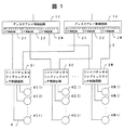
以下、図面を用いて本発明を適用した外部記憶装置(ディスクサブシステム)の実施例を説明する。図1は全体図である。
【0010】
図に示す外部記憶装置において、N個のディスクアレイ制御回路(制御部)(1−1)〜(1−N)(途中の1−2等は省略、以下同じ)は、上位側はホストコンピュータ(図示せず)に接続され、下位側はM個のディスクドライブインターフェイス(ディスクドライブI/F)制御回路(2−1)〜(2−M)を備えている。ディスクアレイ制御回路のハード構成の詳細は後述する。M個のファイバチャネル・ファブリック・スイッチ制御回路(3−1)〜(3−M)は、ファイバチャネル・インタフェース5によってディスクドライブを制御するディスクドライブインターフェイス(I/F)制御回路(2−1)〜(2−M)にそれぞれ接続されている。そして一つのファイバチャネル・ファブリック・スイッチ制御回路に対してL個、計M×L個のディスクドライブ(4(1,1)〜4(M,L))は、ファイバチャネル・インタフェース6によって、ファイバチャネル・ファブリック・スイッチ制御回路(3−1)〜(3−M)と接続されている。
【0011】
また、各ディスクドライブインタフェース制御回路(2−1)〜(2−M)、及びデータを格納しておくディスクドライブ4(1,1)〜4(M,L)はそれぞれ個別の識別子(ID番号)をもつ。ファイバチャネル・ファブリック・スイッチ制御回路(3−1)〜(3−M)は、ディスクドライブインタフェース制御回路(2−1)〜(2−M)から接続するディスクドライブのID番号を受け取り、対応するディスクドライブインタフェース制御回路(2−1)〜(2−M)とディスクドライブ4(1,1)〜4(M,L)の1対1の接続を確立する。
【0012】
図2にディスクアレイ制御回路(1−1)〜(1−N)のハードウェア構成を示す。上位ホストコンピュータ(図示せず)から転送されるデータは、ホストインタフェース制御部7により制御されキャッシュメモリ8に一時格納されると共にパリティデータ生成部9によりパリティデータを付加され、データブロックとパリティデータブロックとに分解(全体でM個)される。これらのデータ及びパリティのブロックは、それぞれ対応するインタフェースであるディスクドライブインタフェース制御回路(2−1)〜(2−M)によりディスクドライブグループ(図示せず)に格納される。
【0013】
上位ホストコンピュータにデータを転送する場合は、転送するデータがキャッシュメモリ8に存在する場合には、そのデータをホストインタフェース制御部7が上位ホストコンピュータに転送する。転送するデータがキャッシュメモリ8に存在しない場合には、ディスクドライブインタフェース制御回路(2−1)〜(2−M)がディスクドライブグループより分解されたデータを読み出し、パリティデータ生成部9で分解されたデータを結合した後にキャッシュメモリ8に一時格納するとともにホストインタフェース制御部7が上位ホストコンピュータに転送する。
【0014】
なお、以上の例はRAIDを用いた場合のデータ格納方法であり、RAID方式を用いずにデータを格納することも当然可能である。その場合にはパリティデータ生成部9が存在せずに上位ホストコンピュータ(図示せず)から転送されるデータは、ホストインタフェース制御部7によりキャッシュメモリ8に一時格納されると共にディスクドライブグループ内の何れかのディスクドライブに格納され、ミラー方式の場合には、複数のディスクドライブに同一のデータを複数格納する。読み出す際にもディスクドライブからデータを読み出し、キャッシュメモリ8に一時格納するとともにホストインタフェース制御部7が上位ホストコンピュータに転送する。
【0015】
以下の例もRAIDを使用したディスクサブシステムについて説明するが、RAIDを用いた場合に限らないことはもちろんである。
【0016】
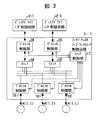
図3にファイバチャネル・ファブリック・スイッチ制御回路(3−1)〜(3−M)のハードウェア構成を示す。ディスクドライブインタフェース制御回路(2−1)と接続されるプロトコル制御部16(第一のプロトコル制御部)は、アクセス対象となるディスクドライブ4(1,1)〜4(1,L)のID番号検出及びファイバチャネル・プロトコルの制御を行う。ディスクドライブ4(1,1)〜4(1,L)と接続されるプロトコル制御部16’(第二のプロトコル制御部)はディスクドライブ4(1,1)〜4(1,L)にID番号を割り付け、スイッチ制御部17に担当するディスクドライブ4(1,1)〜4(1,L)のID番号を報告する。スイッチ制御部17は、各ディスクドライブ4(1,1)〜4(1,L)のID番号を記憶しており、ディスクドライブインタフェース制御回路(2−1)〜(2−M)より受領したID番号によりスイッチ18を設定し、1対1の接続を確立する。
【0017】
尚、プロトコル制御はプロトコル制御部16’側で行うように設定してもよいし、ホストコンピュータからのデータ転送時とホストコンピュータへデータ転送時とや、通常のデータ転送とディスク障害時のデータ移送とでプロトコル制御部16とプロトコル制御部16’とを切り換えるように設定してもよい。
【0018】
また、プロトコル制御部16或いはプロトコル制御部16’の何れか一方のみとし、プロトコル制御部16の代わりにID番号検出手段を設ける、或いはプロトコル制御部16’の代わりにID番号割り付け手段を設けてもよい。
【0019】
また、ファイバチャネル・ファブリック・スイッチを独立した装置としてではなく、ディスクドライブインターフェイス制御回路(2−1)〜(2−M)内にプロトコル制御部とスイッチとを設け、直にディスクドライブ4(1,1)〜4(1,L)と接続するようにしてもよい。
【0020】
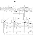
図4にファイバチャネルファブリックスイッチ制御回路(3−1)〜(3−M)の動作を示す。
【0021】
ディスクアレイ制御回路(1−1)は、M個に分解されたデータをディスクドライブグループ(10−1)に格納する。この際、ディスクアレイ制御回路(1−1)のM個のディスクドライブインタフェース制御回路(2−1)〜(2−M)は、ファイバチャネル・ファブリック・スイッチ制御回路(3−1)〜(3−M)に対し、ディスクドライブグループ(10−1)に属するディスクドライブのID番号を送信し、スイッチの確立を行う。ファイバチャネル・ファブリック・スイッチ制御回路(3−1)〜(3−M)内のプロトコル制御部16(図3参照)は、ID番号を検出し、スイッチ制御部17にスイッチ接続の切替を要求する。そしてディスクドライブに合わせたプロトコル制御を行う。スイッチ制御部17(図3参照)はスイッチ18(図3参照)を接続要求もとのディスクアレイ制御回路(1−1)と接続要求先のディスクドライブグループ(10−1)に属するディスクドライブ4とを接続するよう切り替える。
【0022】
このとき、ディスクアレイ制御回路(1−1)は、ディスクドライブグループ(10−1)とファイバチャネル・ファブリック・スイッチ制御回路(3−1)〜(3−M)を介して1対1で対応しているので、他のディスクアレイ制御回路(1−N)と他のディスクドライブグループ(10−2)は独立して他のデータ転送を行うことが出来る。つまり、ディスクアレイ制御回路(1−N)がディスクドライブグループ(10−L)に対する接続の確立を行っても、ディスクアレイ制御回路(1−1)とディスクドライブグループ(10−1)及びディスクアレイ制御回路(1−N)とディスクドライブグループ(10−L)との接続は互いに独立して動作することができるので、それぞれのディスクアレイ制御回路及びディスクドライブ間で可能となる最高のデータ転送速度でデータ転送を行うことができる。
【0023】
尚、詳細は説明しないが、スイッチ制御部17は上記のスイッチ切換えを行うと共に、データ読み書きの際にディスクドライブが既に読み書きを出来る状態になったという信号を受けてスイッチ18の接続切換えを行うことで転送時間を有効に最大限確保することができる。
【0024】
図5に本発明の拡張された実施例を示す。先に示した実施例において、ファイバチャネル・ファブリック・スイッチ制御回路3のプロトコル制御部16とディスクドライブ4とを1対1で対応させて接続していた部分を、プロトコル制御部16からファイバチャネル・アービトレイテッド・ループ制御回路11を介して複数のディスクドライブ4をループ接続するしている。この様に接続することで、安価なディスクドライブ4を多数の接続することで大容量のディスクドライブを備えた場合と同等な性能にできる。この場合でも、全てのディスクドライブがループ接続となる訳ではなく、見かけ上はファイバチャネル・アービトレイテッド・ループ制御回路11と多数のディスクドライブ4で一つのディスクドライブ4であるので、アクセス性能は低下することがない。
【0025】
また図示はしないが、ディスクドライブのアクセス速度に対し、ファイバチャネルインタフェースの最大データ転送速度に充分余裕がある場合には、複数のディスクドライブ4をファイバチャネル・アービトレイテッド・ループ制御回路11に接続し、複数のディスクドライブを同一ループ内に接続し、ファイバチャネルの最大転送レートを複数のディスクドライブ4で共有することで、アクセス性能を低下させることなくディスクドライブ4を増加させることも可能である。
【0026】
図6に図5に示した実施例に用いるアービトレイテッドループ制御回路11のハードウェア構成図を示す。
【0027】
アービトレイテッドループ制御回路11は、ループバイパス回路13と複数のディスクドライブ接続ポート12、及びファブリックスイッチ接続ポート15からなる。ディスクドライブ4からはループバイパス回路切替信号14が出力され、ディスクドライブ障害時にはポートをバイパスさせ、ループを切断することなく、他の動作しているディスクドライブへ影響を与えずにディスクドライブの取り外し、追加を行うことを可能とする。
【0028】
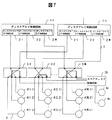
図7に本発明の他の拡張された実施例を示す。
【0029】
本実施例は、各ファイバチャネル・ファブリック・スイッチ制御回路(3−1)〜(3−M)に接続されるスペアディスク制御回路19と、このスペアディスク制御回路19に接続される複数のスペアディスクドライブ(4−a),(4−b)を備えている。そしてファイバチャネル・ファブリック・スイッチ制御回路3内では、故障したディスクドライブ4を含むディスクドライブグループ(図では4(1,2)のディスクドライブグループ)と接続しているプロトコル制御部16’(図3参照)は、スイッチ18を介してスペアディスク制御回路19と接続しているプロトコル制御部16’に接続される。何れかのディスクドライブが障害を起こした場合、ディスクアレイ制御回路(1−1)〜(1−N)は、スペアディスクドライブ(4−a)または(4−b)にデータの再構築を行う。
【0030】
特定のディスクドライブ4にエラーが多発し故障のおそれが出た場合には、エラーが多発するディスクドライブ4のデータをスペアディスクドライブ(4−a)または(4−b)に移管させ再構築を行う。ディスクドライブ4が完全に破損してしまいデータの移管が不可能な場合には、破損したディスクドライブ4のディスクドライブグループのデータを用いて、図2に示したキャッシュメモリ8とパリティデータ生成部9にて破損データを再生しスペアディスクドライブ(4−a)または(4−b)に書き込む。
【0031】
或いは、スペアディスク制御回路19が独立して行うようにしてもよい。そのためこのスペアディスク制御回路19内にキャッシュメモリやパリティデータ再生部を備える。そして、ディスクドライブ4が完全に破損した場合には、残りのディスクドライブグループのデータをスペアディスク制御回路19で読み込み、破損データを再生してスペアディスクドライブ(4−a)または(4−b)に書き込むようにする。
【0032】
そのため、故障したディスクドライブ4或いは故障個所を修復するためにパリティデータを含め分割されたデータを記憶した各ディスクドライブからスペアディスク制御回路19へのアクセスと、ディスクアレイ制御回路(1−1)〜(1−N)を介して行うディスクドライブ4(図では4(1,1)及び4(1,L)のディスクドライブグループ)とホストコンピュータからのデータアクセスとが独立して動作可能となることで、ホストコンピュータのデータアクセスに影響を与えずにデータの再構築を行うことを可能とする。
【0033】
また、障害ディスクドライブが正常ディスクドライブと取り替えられた場合も同様にして、スペアディスク制御回路15がファイバチャネル・ファブリック・スイッチ制御回路(3−1)〜(3−M)に対し、スペアディスクドライブ(4−a),(4−b)と、障害ディスクドライブから取り替えられた正常ディスクドライブと1対1の接続を行い、ディスクアレイ制御回路(1−1)〜(1−N)とディスクドライブグループ(10−1)〜(10−L)(図4参照)とのアクセスを妨げることなく、独立してデータのコピーを行うことで、ホストコンピュータからのアクセスにまったく影響なく障害ディスクドライブの復旧を行うことができる。
【0034】
【発明の効果】
本発明により、シリアルインタフェースであるファイバチャネルインタフェースを用い接続線数を減少させ、さらにスイッチ接続を可能とするファイバチャネル・ファブリック・トポロジを用いることでディスクドライブインタフェース回路に多数ディスクドライブを伝送性能を犠牲にすることなく接続することが可能となる。また、各制御装置、ディスクドライブグループ毎に接続を動的に切り替えることで、少数のディスクドライブ制御回路で多数のディスクドライブを制御することができる。更に、ディスクドライブ障害時のデータ移行をディスクドライブインタフェース制御回路とディスクドライブのデータ転送と独立して行うことでシステムの信頼性を向上させることができる。
【図面の簡単な説明】
【図1】本発明実施例の全体図である。
【図2】ディスクアレイ制御回路の詳細図である。
【図3】ファイバチャネルファブリックスイッチ制御回路の詳細図である。
【図4】ファイバチャネルファブリックスイッチの接続図である。
【図5】ファイバチャネルファブリックスイッチとアービトレイテッドループの接続図である。
【図6】ファイバチャネルアービトレイテッドループ制御回路の詳細図である。
【図7】スペアディスク制御回路の接続図である。
【符号の説明】
1…ディスクアレイ制御回路、2…ディスクドライブインタフェース制御回路、3…ファイバチャネルファブリックスイッチ制御回路、4…ディスクドライブ、5…ファイバチャネルインタフェース、6…ファイバチャネルインタフェース、7…ホストインタフェース制御部、8…キャッシュメモリ、9…パリティデータ生成部、10…ディスクドライブグループ、11…ファイバチャネルアービトレイテッドループ制御回路、12…ディスクドライブ接続ポート、13…ループバイパス回路、14…ループバイパス信号切替信号、15…ファブリックスイッチ接続ポート、16…プロトコル制御部、17…スイッチ制御部、18…スイッチ、19…スペアディスク制御回路。[0001]
BACKGROUND OF THE INVENTION
The present invention relates to an electronic apparatus such as a disk subsystem, a disk array, and a computer having a built-in disk drive, and more particularly to a technique that enables high-speed transfer by connecting array disks to a fabric switch.
[0002]
[Prior art]
In general, when a disk controller and a plurality of disk drives are connected in a disk array, a SCSI interface or a fiber channel arbitrated loop topology is used as described in JP-A-10-171746. Yes.
[0003]
The SCSI interface employs a method of transferring data on the same line in a time-sharing manner, and access to the initiator is a method of performing one-to-one communication per time on one transmission line.
[0004]
In the Fiber Channel Arbitrated Loop topology, the initiator and disk drive can be connected in a loop with the serial interface to the SCSI interface, and the data divided into frames is transferred in a time-sharing manner, and many Devices can communicate and the number of connectable disk drives can be expanded to 126.
[0005]
[Problems to be solved by the invention]
In the future, it will be possible to use more disk drives by reducing the size and increasing the density of disk drives.
[0006]
Since the SCSI interface is a system that performs one-to-one communication per time on one transmission path, communication between a large number of initiators and disk drives cannot be performed simultaneously. Also, the number of connectable disk drives is as small as 7 to 15. For this reason, when one-to-one connection is made with one interface when the number of drives is increased by an interface using SCSI, a large number of interfaces are required, resulting in difficulty in mounting. Further, since the number of disk drives that can be connected by one control circuit is small, it is necessary to use a large number of control circuits.
[0007]
On the other hand, when using Fiber Channel, the disk drive protocol cannot be switched because the protocol is different from that of the controller, and loop connection using a Fiber Channel arbitrated loop in which many disk drives share the same loop. I had to. Therefore, when the number of disk drives connected to the same loop is increased, the data transfer speed of the disk drive becomes larger than the maximum data transfer speed of the loop, and as a result, transfer cannot be performed with an efficiency exceeding the maximum data transfer speed of the loop. Connection was possible only at the same data transfer speed as the SCSI interface.
[0008]
[Means for Solving the Problems]
In order to solve the above problems, in the present invention, a protocol control unit is provided between the fiber channel fabric switch and the disk drive in order to enable switch connection between the disk drive and the control device.
[0009]
DETAILED DESCRIPTION OF THE INVENTION
Embodiments of an external storage device (disk subsystem) to which the present invention is applied will be described below with reference to the drawings. FIG. 1 is an overall view.
[0010]
In the external storage device shown in the figure, N disk array control circuits (control units) (1-1) to (1-N) (1-2 in the middle are omitted; the same applies hereinafter) are arranged on the host computer. The lower side includes M disk drive interface (disk drive I / F) control circuits (2-1) to (2-M). Details of the hardware configuration of the disk array control circuit will be described later. M fiber channel fabric switch control circuits (3-1) to (3-M) are disk drive interface (I / F) control circuits (2-1) for controlling the disk drive by the
[0011]
Each of the disk drive interface control circuits (2-1) to (2-M) and the disk drives 4 (1, 1) to 4 (M, L) for storing data have their respective identifiers (ID numbers). ) The Fiber Channel fabric switch control circuits (3-1) to (3-M) receive the ID numbers of the disk drives to be connected from the disk drive interface control circuits (2-1) to (2-M) and correspond to them. A one-to-one connection between the disk drive interface control circuits (2-1) to (2-M) and the disk drives 4 (1, 1) to 4 (M, L) is established.
[0012]
FIG. 2 shows a hardware configuration of the disk array control circuits (1-1) to (1-N). Data transferred from a host computer (not shown) is controlled by the host interface control unit 7 and temporarily stored in the
[0013]
When transferring data to the host computer, if the data to be transferred exists in the
[0014]
Note that the above example is a data storage method when RAID is used, and it is naturally possible to store data without using the RAID system. In this case, the data transferred from the host computer (not shown) without the parity
[0015]
The following example also describes a disk subsystem using RAID, but of course it is not limited to using RAID.
[0016]
FIG. 3 shows the hardware configuration of the fiber channel fabric switch control circuits (3-1) to (3-M). The protocol control unit 16 (first protocol control unit) connected to the disk drive interface control circuit (2-1) determines the ID numbers of the disk drives 4 (1, 1) to 4 (1, L) to be accessed. Performs detection and Fiber Channel protocol control. The
[0017]
Protocol control may be set to be performed on the protocol control unit 16 'side, data transfer from the host computer, data transfer to the host computer, normal data transfer, and data transfer at the time of disk failure And the
[0018]
Further, only one of the
[0019]
In addition, the protocol control unit and the switch are provided in the disk drive interface control circuits (2-1) to (2-M) instead of the fiber channel fabric switch as an independent device, and the disk drive 4 (1 , 1) to 4 (1, L).
[0020]
FIG. 4 shows operations of the fiber channel fabric switch control circuits (3-1) to (3-M).
[0021]
The disk array control circuit (1-1) stores the data divided into M pieces in the disk drive group (10-1). At this time, the M disk drive interface control circuits (2-1) to (2-M) of the disk array control circuit (1-1) are connected to the fiber channel fabric switch control circuits (3-1) to (3). -M), the ID number of the disk drive belonging to the disk drive group (10-1) is transmitted to establish the switch. The protocol control unit 16 (see FIG. 3) in the fiber channel fabric switch control circuits (3-1) to (3-M) detects the ID number and requests the switch control unit 17 to switch the switch connection. . Protocol control is performed according to the disk drive. The switch control unit 17 (see FIG. 3) connects the switch 18 (see FIG. 3) to the disk array control circuit (1-1) that requested the connection request and the
[0022]
At this time, the disk array control circuit (1-1) has a one-to-one correspondence with the disk drive group (10-1) via the fiber channel fabric switch control circuits (3-1) to (3-M). Therefore, the other disk array control circuit (1-N) and the other disk drive group (10-2) can perform other data transfer independently. That is, even if the disk array control circuit (1-N) establishes a connection to the disk drive group (10-L), the disk array control circuit (1-1), the disk drive group (10-1), and the disk array Since the connection between the control circuit (1-N) and the disk drive group (10-L) can operate independently of each other, the highest data transfer speed possible between each disk array control circuit and the disk drive. Can be used to transfer data.
[0023]
Although not described in detail, the switch control unit 17 performs the above-described switch switching and switches the connection of the
[0024]
FIG. 5 shows an expanded embodiment of the present invention. In the embodiment shown above, the
[0025]
Although not shown, when the maximum data transfer rate of the fiber channel interface is sufficient with respect to the access speed of the disk drive, a plurality of
[0026]
FIG. 6 shows a hardware configuration diagram of the arbitrated
[0027]
The arbitrated
[0028]
FIG. 7 shows another expanded embodiment of the present invention.
[0029]
In this embodiment, a spare
[0030]
If errors occur frequently in a
[0031]
Alternatively, the spare
[0032]
Therefore, access to the spare
[0033]
Similarly, when the failed disk drive is replaced with a normal disk drive, the spare
[0034]
【The invention's effect】
The present invention reduces the number of connection lines using a Fiber Channel interface, which is a serial interface, and uses a Fiber Channel fabric topology that enables switch connection, thereby sacrificing the transmission performance of a large number of disk drives in the disk drive interface circuit. It becomes possible to connect without making. Further, by dynamically switching the connection for each control device and each disk drive group, a large number of disk drives can be controlled by a small number of disk drive control circuits. Furthermore, the data migration in the event of a disk drive failure can be performed independently of the disk drive interface control circuit and the disk drive data transfer, thereby improving the system reliability.
[Brief description of the drawings]
FIG. 1 is an overall view of an embodiment of the present invention.
FIG. 2 is a detailed diagram of a disk array control circuit.
FIG. 3 is a detailed diagram of a Fiber Channel fabric switch control circuit.
FIG. 4 is a connection diagram of Fiber Channel fabric switches.
FIG. 5 is a connection diagram of a fiber channel fabric switch and an arbitrated loop.
FIG. 6 is a detailed diagram of a fiber channel arbitrated loop control circuit.
FIG. 7 is a connection diagram of a spare disk control circuit.
[Explanation of symbols]
DESCRIPTION OF
Claims (12)
ホストコンピュータから受信されるデータからパリティデータを生成するものであり、前記複数のディスクドライブにデータ及びパリティデータを転送するディスクドライブインタフェース部を備える、ディスクアレイ制御部と、
前記複数のディスクドライブ及び前記ディスクドライブインタフェース部と接続される複数のスイッチと、を備え、
前記複数のディスクドライブの各々は、少なくとも1つの第1経路を介してポイント・ツー・ポイントで前記複数のスイッチのうち少なくとも1つのスイッチに接続され、
前記複数のディスクドライブのうち第1のディスクドライブと接続される前記第1経路と、前記複数のディスクドライブのうち第2のディスクドライブと接続される前記第1経路とは、相互に異なり、
前記複数のスイッチの各々は、少なくとも1つの第2経路を介して前記ディスクドライブインタフェース部に接続され、
前記複数のスイッチのうちの少なくとも1つのスイッチは、前記ディスクドライブインタフェース部からパリティデータを受信する場合に、当該スイッチに接続される複数のディスクドライブのうちパリティデータの転送先のディスクドライブに接続された第1経路を介して、パリティデータを前記転送先のディスクドライブに転送するものであり、 前記複数のスイッチのうちのその他のスイッチは、前記ディスクドライブインタフェース部からデータを受信する場合に、当該スイッチに接続される複数のディスクドライブのうちデータの転送先のディスクドライブに接続された第1経路を介して、データを前記転送先のディスクドライブに転送するものであることを特徴とするディスクアレイ装置。Multiple disk drives,
A disk array controller that generates parity data from data received from a host computer, and includes a disk drive interface that transfers data and parity data to the plurality of disk drives;
A plurality of switches connected to the plurality of disk drives and the disk drive interface unit,
Each of the plurality of disk drives is connected to at least one of the plurality of switches on a point-to-point basis through at least one first path;
The first path connected to the first disk drive among the plurality of disk drives and the first path connected to the second disk drive among the plurality of disk drives are different from each other.
Each of the plurality of switches is connected to the disk drive interface unit via at least one second path ,
At least one switch of the plurality of switches, when receiving the parity data from the disk drive interface unit, connected to the disk drive of the destination of the parity data of the plurality of disk drives that are connected to the switch and through the first path, der and transfers the parity data to the disk drive of the transfer destination is, other switches of the plurality of switches, when receiving data from the disk drive interface unit, A disk that transfers data to the transfer destination disk drive via a first path connected to a data transfer destination disk drive among a plurality of disk drives connected to the switch. Array device.
前記複数のスイッチの各々は、複数の前記第1経路と前記第2経路との接続を動的に切り替えることを特徴とするディスクアレイ装置。The disk array device according to claim 1,
Wherein each of the plurality of switches, the disk array device and switches the connection between a plurality of said first path and said second path dynamically.
前記複数のディスクドライブの少なくとも1つはスペアディスクドライブであり、前記スペアディスクドライブは、前記複数のディスクドライブの他の1つのディスクドライブのデータ又はパリティデータを格納することを特徴とするディスクアレイ装置。The disk array device according to claim 1,
At least one of the plurality of disk drives is a spare disk drive, and the spare disk drive stores data or parity data of another disk drive of the plurality of disk drives. .
前記第2経路は、ファイバチャネルインタフェースによって通信する経路であることを特徴とするディスクアレイ装置。The disk array device according to claim 1,
The disk array device according to claim 1, wherein the second path is a path for communication by a fiber channel interface.
前記第1経路の数は、前記第2経路の数よりも多いものであることを特徴とするディスクアレイ装置。The disk array apparatus according to claim 1 to 4, wherein,
The disk array device according to claim 1, wherein the number of the first paths is larger than the number of the second paths.
前記複数のスイッチの各々は、前記インタフェース部からデータとパリティデータと前記転送先のディスクドライブの識別情報とを受信し、前記識別情報に基づいてデータ又はパリティデータを前記転送先のディスクドライブに転送することを特徴とするディスクアレイ装置。The disk array apparatus according to claim 1 to 4, wherein,
Each of the plurality of switches receives data, parity data, and identification information of the transfer destination disk drive from the interface unit, and transfers data or parity data to the transfer destination disk drive based on the identification information And a disk array device.
ホストコンピュータから受信されるデータからパリティデータを生成するものであり、前記複数のディスクドライブにデータ又はパリティデータを転送するディスクドライブインタフェース部を備える、ディスクアレイ制御部と、
前記複数のディスクドライブ及び前記ディスクドライブインタフェース部と接続される複数のスイッチと、を備え、
前記複数のディスクドライブの各々は、少なくとも1つの第1経路を介してポイント・ツー・ポイントで前記複数のスイッチのうちの少なくとも一つのスイッチに接続され、
前記複数のディスクドライブのうち第1のディスクドライブと接続される前記第1経路と、前記複数のディスクドライブのうち第2のディスクドライブと接続される前記第1経路とは、相互に異なり、
前記複数のスイッチの各々は、少なくとも1つの第2経路を介して前記ディスクドライブインタフェース部に接続され、
前記複数のスイッチのうちの少なくとも1つのスイッチは、前記第2経路を介して受信するパリティデータを、当該スイッチに接続される複数のディスクドライブの中から選択された転送先のディスクドライブに対して、前記転送先のディスクドライブに接続された第1経路を介して転送するものであり、
前記複数のスイッチのうちのその他のスイッチは、前記第2経路を介して受信するデータを、当該スイッチに接続される複数のディスクドライブの中から選択された転送先のディスクドライブに対して、前記転送先のディスクドライブに接続された第1経路を介して転送するものであることを特徴とするディスクアレイ装置。Multiple disk drives where data is stored;
A disk array control unit that generates parity data from data received from a host computer, and includes a disk drive interface unit that transfers data or parity data to the plurality of disk drives;
A plurality of switches connected to the plurality of disk drives and the disk drive interface unit,
Each of the plurality of disk drives is connected to at least one of the plurality of switches in a point-to-point manner via at least one first path;
The first path connected to the first disk drive among the plurality of disk drives and the first path connected to the second disk drive among the plurality of disk drives are different from each other.
Each of the plurality of switches is connected to the disk drive interface unit via at least one second path ,
At least one of the plurality of switches receives parity data received via the second path with respect to a transfer destination disk drive selected from the plurality of disk drives connected to the switch . state, and it is not transferred through the first path connected to the destination disk drive,
The other switches of the plurality of switches, with respect to the transfer destination disk drive selected from among the plurality of disk drives connected to the switch, the data received via the second path, the disk array device according to claim der Rukoto and transfers through the first path connected to the destination of the disk drive.
前記第1経路の数は、前記第2経路の数よりも多いものであることを特徴とするディスクアレイ装置。The disk array device according to claim 7 , wherein
The disk array device according to claim 1, wherein the number of the first paths is larger than the number of the second paths.
前記複数のスイッチの各々は、前記少なくとも1つの第2経路を介して、データとパリティデータと前記転送先のディスクドライブの識別情報とを受信し、前記識別情報に基づいてデータを前記転送先のディスクドライブに転送することを特徴とするディスクアレイ装置。The disk array device according to claim 7 , wherein
Each of the plurality of switches receives data, parity data, and identification information of the transfer destination disk drive via the at least one second path, and transfers the data based on the identification information to the transfer destination A disk array device that transfers to a disk drive.
ホストコンピュータから受信されるデータからパリティデータを生成するものであり、前記複数のディスクドライブにデータ又はパリティデータを転送するディスクドライブインタフェース部を備える、ディスクアレイ制御部と、
前記複数のディスクドライブ及び前記ディスクドライブインタフェース部と接続される複数のスイッチと、を備え、
前記複数のディスクドライブの各々は、少なくとも1つの第1経路を介してポイント・ツー・ポイントで前記複数のスイッチのうち少なくとも1つのスイッチに接続され、
前記複数のディスクドライブのうち第1のディスクドライブと接続される前記第1経路と、前記複数のディスクドライブのうち第2のディスクドライブと接続される前記第1経路とは、相互に異なり、
前記複数のスイッチの各々は、少なくとも1つの第2経路を介して前記ディスクドライブインタフェース部に接続され、
前記複数のスイッチのうちの少なくとも1つのスイッチは、前記第2経路を介してパリティデータを受信する場合に、当該スイッチ内部の接続関係を切替え、前記受信したパリティデータを前記第1経路を介して当該スイッチに接続される複数のディスクドライブのうちの1つのディスクドライブに転送し、
前記複数のスイッチのうちのその他のスイッチは、前記第2経路を介してデータを受信する場合に、当該スイッチ内部の接続関係を切替え、前記受信したデータを前記第1経路を介して当該スイッチに接続される複数のディスクドライブのうちの1つのディスクドライブに転送することを特徴とするディスクアレイ装置。Multiple disk drives,
A disk array control unit that generates parity data from data received from a host computer, and includes a disk drive interface unit that transfers data or parity data to the plurality of disk drives;
A plurality of switches connected to the plurality of disk drives and the disk drive interface unit,
Each of the plurality of disk drives is connected to at least one of the plurality of switches on a point-to-point basis through at least one first path;
The first path connected to the first disk drive among the plurality of disk drives and the first path connected to the second disk drive among the plurality of disk drives are different from each other.
Each of the plurality of switches is connected to the disk drive interface unit via at least one second path ,
At least one switch of the plurality of switches, when receiving the parity data via the second path, switching the switches inside the connection relationship, the parity data thus received via the first path Transfer to one of the multiple disk drives connected to the switch ,
When the other switch of the plurality of switches receives data via the second path, it switches the connection relationship inside the switch, and the received data is transferred to the switch via the first path. A disk array device that transfers data to one of a plurality of connected disk drives .
前記第1経路の数は、前記第2経路の数よりも多いものであることを特徴とするディスクアレイ装置。The disk array device according to claim 10 , wherein
The disk array device according to claim 1, wherein the number of the first paths is larger than the number of the second paths.
前記複数のスイッチの各々は、前記第2経路を介して、データと、パリティデータと、データの転送先のディスクドライブを示す識別情報と、を受信し、前記識別情報に基づいてデータを前記転送先のディスクドライブに転送することを特徴とするディスクアレイ装置。The disk array device according to claim 10 ,
Each of the plurality of switches receives data, parity data, and identification information indicating a disk drive that is a data transfer destination via the second path, and transfers the data based on the identification information. A disk array device that transfers to a previous disk drive.
Priority Applications (9)
| Application Number | Priority Date | Filing Date | Title |
|---|---|---|---|
| JP02464899A JP4294142B2 (en) | 1999-02-02 | 1999-02-02 | Disk subsystem |
| US09/495,868 US6542954B1 (en) | 1999-02-02 | 2000-02-02 | Disk subsystem |
| US10/337,397 US6976116B2 (en) | 1999-02-02 | 2003-01-07 | Disk subsystem |
| US10/615,907 US7032062B2 (en) | 1999-02-02 | 2003-07-10 | Disk subsystem |
| US10/632,855 US6883059B2 (en) | 1999-02-02 | 2003-08-04 | Disk subsystem |
| US10/933,387 US7836249B2 (en) | 1999-02-02 | 2004-09-03 | Disk subsystem |
| US12/892,341 US8234437B2 (en) | 1999-02-02 | 2010-09-28 | Disk subsystem |
| US13/544,163 US8554979B2 (en) | 1999-02-02 | 2012-07-09 | Disk subsystem |
| US14/019,588 US8949503B2 (en) | 1999-02-02 | 2013-09-06 | Disk subsystem |
Applications Claiming Priority (1)
| Application Number | Priority Date | Filing Date | Title |
|---|---|---|---|
| JP02464899A JP4294142B2 (en) | 1999-02-02 | 1999-02-02 | Disk subsystem |
Related Child Applications (1)
| Application Number | Title | Priority Date | Filing Date |
|---|---|---|---|
| JP2003396500A Division JP4444636B2 (en) | 2003-11-27 | 2003-11-27 | Disk subsystem |
Publications (3)
| Publication Number | Publication Date |
|---|---|
| JP2000222339A JP2000222339A (en) | 2000-08-11 |
| JP2000222339A5 JP2000222339A5 (en) | 2004-11-18 |
| JP4294142B2 true JP4294142B2 (en) | 2009-07-08 |
Family
ID=12143970
Family Applications (1)
| Application Number | Title | Priority Date | Filing Date |
|---|---|---|---|
| JP02464899A Expired - Fee Related JP4294142B2 (en) | 1999-02-02 | 1999-02-02 | Disk subsystem |
Country Status (2)
| Country | Link |
|---|---|
| US (8) | US6542954B1 (en) |
| JP (1) | JP4294142B2 (en) |
Families Citing this family (74)
| Publication number | Priority date | Publication date | Assignee | Title |
|---|---|---|---|---|
| JP4294142B2 (en) | 1999-02-02 | 2009-07-08 | 株式会社日立製作所 | Disk subsystem |
| US7424529B2 (en) * | 1999-12-10 | 2008-09-09 | International Business Machines Corporation | System using host bus adapter connection tables and server tables to generate connection topology of servers and controllers |
| US6769046B2 (en) * | 2000-02-14 | 2004-07-27 | Palmchip Corporation | System-resource router |
| JP2002014777A (en) * | 2000-06-29 | 2002-01-18 | Hitachi Ltd | Data moving method and protocol converting device, and switching device using the same |
| US6754682B1 (en) * | 2000-07-10 | 2004-06-22 | Emc Corporation | Method and apparatus for enabling consistent ancillary disk array storage device operations with respect to a main application |
| US6980510B1 (en) * | 2000-09-12 | 2005-12-27 | International Business Machines Corporation | Host interface adaptive hub storage system |
| US6763409B1 (en) * | 2001-01-31 | 2004-07-13 | Hewlett-Packard Development Company, L.P. | Switch-on-the-fly GBIC disk channel adapter and disk channel system |
| US6816982B2 (en) * | 2001-03-13 | 2004-11-09 | Gonen Ravid | Method of and apparatus for computer hard disk drive protection and recovery |
| GB2374749B (en) * | 2001-04-20 | 2005-04-06 | Discreet Logic Inc | Image data processing |
| GB2374769B (en) * | 2001-04-20 | 2004-07-21 | Discreet Logic Inc | Network system for data processing systems and data storage systems |
| US6813676B1 (en) * | 2001-07-27 | 2004-11-02 | Lsi Logic Corporation | Host interface bypass on a fabric based array controller |
| JP4156817B2 (en) * | 2001-07-27 | 2008-09-24 | 株式会社日立製作所 | Storage system |
| US7010620B1 (en) * | 2001-12-06 | 2006-03-07 | Emc Corporation | Network adapter having integrated switching capabilities and port circuitry that may be used in remote mirroring |
| JP3714613B2 (en) * | 2001-12-12 | 2005-11-09 | インターナショナル・ビジネス・マシーンズ・コーポレーション | Storage device, information processing device including the storage device, and information storage system recovery method |
| JP2003303055A (en) * | 2002-04-09 | 2003-10-24 | Hitachi Ltd | Disk device connecting disk adapter and array through switch |
| US7073022B2 (en) * | 2002-05-23 | 2006-07-04 | International Business Machines Corporation | Serial interface for a data storage array |
| US6928514B2 (en) * | 2002-08-05 | 2005-08-09 | Lsi Logic Corporation | Method and apparatus for teaming storage controllers |
| JP4439798B2 (en) * | 2002-10-17 | 2010-03-24 | 株式会社日立製作所 | Disk array device control method and disk array device |
| US6957303B2 (en) * | 2002-11-26 | 2005-10-18 | Hitachi, Ltd. | System and managing method for cluster-type storage |
| JP2004192105A (en) * | 2002-12-09 | 2004-07-08 | Hitachi Ltd | Connection device of storage device and computer system including it |
| US7287102B1 (en) * | 2003-01-31 | 2007-10-23 | Marvell International Ltd. | System and method for concatenating data |
| JP4651913B2 (en) | 2003-02-17 | 2011-03-16 | 株式会社日立製作所 | Storage system |
| US7360010B2 (en) * | 2003-04-14 | 2008-04-15 | Copan Systems, Inc. | Method and apparatus for storage command and data router |
| US7571280B2 (en) * | 2003-04-25 | 2009-08-04 | Hitachi, Ltd. | Cluster-type storage system and managing method of the cluster-type storage system |
| JP2004348464A (en) * | 2003-05-22 | 2004-12-09 | Hitachi Ltd | Storage device and communication signal shaping circuit |
| JP4060235B2 (en) * | 2003-05-22 | 2008-03-12 | 株式会社日立製作所 | Disk array device and disk array device control method |
| US20050100042A1 (en) * | 2003-11-12 | 2005-05-12 | Illikkal Rameshkumar G. | Method and system to pre-fetch a protocol control block for network packet processing |
| JP4220887B2 (en) * | 2003-11-17 | 2009-02-04 | 株式会社日立製作所 | Disk device and control method thereof |
| EP1533704A3 (en) * | 2003-11-21 | 2007-03-07 | Hitachi, Ltd. | Read/write protocol for cache control units at switch fabric, managing caches for cluster-type storage |
| JP4156499B2 (en) * | 2003-11-28 | 2008-09-24 | 株式会社日立製作所 | Disk array device |
| US7111158B1 (en) * | 2003-12-24 | 2006-09-19 | Emc Corporation | Techniques for transitioning control of a serial ATA device among multiple hosts using sleep and wake commands |
| JP4497918B2 (en) * | 2003-12-25 | 2010-07-07 | 株式会社日立製作所 | Storage system |
| US7187819B1 (en) | 2003-12-31 | 2007-03-06 | Storage Technology Corporation | Optical power distribution management and apparatus |
| JP2005196331A (en) | 2004-01-05 | 2005-07-21 | Hitachi Ltd | Disk array system and reconfiguration method of disk array system |
| JP4518541B2 (en) * | 2004-01-16 | 2010-08-04 | 株式会社日立製作所 | Disk array device and disk array device control method |
| US8024490B2 (en) * | 2004-01-28 | 2011-09-20 | Seagate Technology Llc | Method and system for generic data transfer interface |
| US8006056B2 (en) | 2004-01-30 | 2011-08-23 | Hewlett-Packard Development Company, L.P. | Storage system including capability to move a virtual storage device group without moving data |
| JP4634049B2 (en) | 2004-02-04 | 2011-02-16 | 株式会社日立製作所 | Error notification control in disk array system |
| JP4441286B2 (en) * | 2004-02-10 | 2010-03-31 | 株式会社日立製作所 | Storage system |
| JP4405277B2 (en) * | 2004-02-16 | 2010-01-27 | 株式会社日立製作所 | Disk controller |
| US7467238B2 (en) * | 2004-02-10 | 2008-12-16 | Hitachi, Ltd. | Disk controller and storage system |
| JP2005267502A (en) * | 2004-03-22 | 2005-09-29 | Hitachi Ltd | Switch for data transfer |
| JP4528551B2 (en) * | 2004-04-14 | 2010-08-18 | 株式会社日立製作所 | Storage system |
| US20050283654A1 (en) * | 2004-05-24 | 2005-12-22 | Sun Microsystems, Inc. | Method and apparatus for decreasing failed disk reconstruction time in a raid data storage system |
| JP2006072717A (en) | 2004-09-02 | 2006-03-16 | Hitachi Ltd | Disk subsystem |
| US20060106947A1 (en) * | 2004-11-18 | 2006-05-18 | Benhase Michael T | Information storage and retrieval system comprising a storage controller and a fibre channel switch controller |
| EP2296085B1 (en) * | 2004-11-30 | 2013-05-15 | Fujitsu Limited | Data storage system and capacity changing method |
| US7668196B2 (en) * | 2005-01-25 | 2010-02-23 | International Business Machines Corporation | Communicating between communications components having differing protocols absent component modifications |
| JP4321464B2 (en) * | 2005-03-11 | 2009-08-26 | ヤマハ株式会社 | Information recording apparatus and program |
| JP4969795B2 (en) * | 2005-05-12 | 2012-07-04 | 株式会社日立製作所 | Storage control system |
| TWI292113B (en) * | 2005-09-28 | 2008-01-01 | Asustek Comp Inc | Electronic device and control module |
| JP4817783B2 (en) * | 2005-09-30 | 2011-11-16 | 富士通株式会社 | RAID system and rebuild / copyback processing method thereof |
| JP4472617B2 (en) * | 2005-10-28 | 2010-06-02 | 富士通株式会社 | RAID system, RAID controller and rebuild / copy back processing method thereof |
| NZ569517A (en) | 2006-02-07 | 2011-07-29 | Lundbeck & Co As H | Use of KCNQ-openers for threating or reducing the symptoms of schizophrenia |
| JP4546413B2 (en) * | 2006-03-17 | 2010-09-15 | 富士通株式会社 | Parallel computer reduction processing method and parallel computer |
| JP4799273B2 (en) * | 2006-05-25 | 2011-10-26 | 富士通株式会社 | Storage system and automatic recovery method in case of loop error |
| US7472211B2 (en) | 2006-07-28 | 2008-12-30 | International Business Machines Corporation | Blade server switch module using out-of-band signaling to detect the physical location of an active drive enclosure device |
| US20080123677A1 (en) * | 2006-08-31 | 2008-05-29 | Honeywell International Inc. | System management bus port switch |
| US7496717B2 (en) * | 2006-09-12 | 2009-02-24 | Inventec Corporation | System for sharing storage device among controllers and method thereof |
| JP4354492B2 (en) | 2007-01-31 | 2009-10-28 | 富士通株式会社 | Disk drive diagnostic device |
| JP5068086B2 (en) * | 2007-02-16 | 2012-11-07 | 株式会社日立製作所 | Storage controller |
| JP5494028B2 (en) * | 2010-03-09 | 2014-05-14 | 富士通株式会社 | Switch device |
| US9311018B2 (en) * | 2010-05-11 | 2016-04-12 | Taejin Info Tech Co., Ltd. | Hybrid storage system for a multi-level RAID architecture |
| CN102375699A (en) * | 2010-08-23 | 2012-03-14 | 英业达股份有限公司 | Storage system |
| US9229816B2 (en) * | 2011-03-14 | 2016-01-05 | Taejin Info Tech Co., Ltd. | Hybrid system architecture for random access memory |
| US8694724B1 (en) * | 2011-09-06 | 2014-04-08 | Emc Corporation | Managing data storage by provisioning cache as a virtual device |
| US8775713B2 (en) * | 2011-12-27 | 2014-07-08 | Intel Corporation | Multi-protocol tunneling over an I/O interconnect |
| US8782321B2 (en) | 2012-02-08 | 2014-07-15 | Intel Corporation | PCI express tunneling over a multi-protocol I/O interconnect |
| US8880923B2 (en) | 2012-03-29 | 2014-11-04 | Intel Corporation | Link power management in an I/O interconnect |
| US9268493B2 (en) * | 2012-11-28 | 2016-02-23 | Dell Products L.P. | Systems and methods for smart storage interconnection in a heterogeneous storage environment |
| US20140281673A1 (en) * | 2013-03-15 | 2014-09-18 | Unisys Corporation | High availability server configuration |
| CN107506135B (en) * | 2016-06-14 | 2022-05-06 | 杭州海康威视数字技术股份有限公司 | Data processing method, device and system |
| US11120334B1 (en) | 2017-09-08 | 2021-09-14 | Snap Inc. | Multimodal named entity recognition |
| US10521318B2 (en) * | 2017-10-16 | 2019-12-31 | Dell Products L.P. | Spanned RAID with nested parity |
Family Cites Families (87)
| Publication number | Priority date | Publication date | Assignee | Title |
|---|---|---|---|---|
| US566651A (en) * | 1896-08-25 | Combined saw stretcher and shears | ||
| DE2502621C3 (en) | 1975-01-23 | 1978-09-14 | Kernforschungsanlage Juelich Gmbh, 5170 Juelich | Measurement of elastic and dielectric properties of the membrane of living cells |
| US4144583A (en) | 1977-06-06 | 1979-03-13 | Digital Equipment Corporation | Secondary storage facility with means for monitoring error conditions |
| JPS6119125A (en) | 1984-07-05 | 1986-01-28 | Matsushita Electric Ind Co Ltd | Scanning type exposer |
| US4825354A (en) | 1985-11-12 | 1989-04-25 | American Telephone And Telegraph Company, At&T Bell Laboratories | Method of file access in a distributed processing computer network |
| US5077736A (en) * | 1988-06-28 | 1991-12-31 | Storage Technology Corporation | Disk drive memory |
| US4937763A (en) | 1988-09-06 | 1990-06-26 | E I International, Inc. | Method of system state analysis |
| US5067099A (en) | 1988-11-03 | 1991-11-19 | Allied-Signal Inc. | Methods and apparatus for monitoring system performance |
| US4984272A (en) | 1988-11-30 | 1991-01-08 | At&T Bell Laboratories | Secure file handling in a computer operating system |
| JPH02165241A (en) | 1988-12-19 | 1990-06-26 | Toshiba Corp | File access system |
| US5222217A (en) | 1989-01-18 | 1993-06-22 | International Business Machines Corporation | System and method for implementing operating system message queues with recoverable shared virtual storage |
| US5113442A (en) | 1989-03-06 | 1992-05-12 | Lachman Associates, Inc. | Method and apparatus for providing access control in a secure operating system |
| US5144659A (en) | 1989-04-19 | 1992-09-01 | Richard P. Jones | Computer file protection system |
| US5140592A (en) * | 1990-03-02 | 1992-08-18 | Sf2 Corporation | Disk array system |
| JPH04165526A (en) * | 1990-10-30 | 1992-06-11 | Toshiba Corp | Disk controller |
| JP3187525B2 (en) | 1991-05-17 | 2001-07-11 | ヒュンダイ エレクトロニクス アメリカ | Bus connection device |
| US5301297A (en) | 1991-07-03 | 1994-04-05 | Ibm Corp. (International Business Machines Corp.) | Method and means for managing RAID 5 DASD arrays having RAID DASD arrays as logical devices thereof |
| US5257391A (en) | 1991-08-16 | 1993-10-26 | Ncr Corporation | Disk controller having host interface and bus switches for selecting buffer and drive busses respectively based on configuration control signals |
| US5237658A (en) | 1991-10-01 | 1993-08-17 | Tandem Computers Incorporated | Linear and orthogonal expansion of array storage in multiprocessor computing systems |
| US5321837A (en) | 1991-10-11 | 1994-06-14 | International Business Machines Corporation | Event handling mechanism having a process and an action association process |
| GB9126779D0 (en) | 1991-12-17 | 1992-02-12 | Int Computers Ltd | Security mechanism for a computer system |
| US5371882A (en) * | 1992-01-14 | 1994-12-06 | Storage Technology Corporation | Spare disk drive replacement scheduling system for a disk drive array data storage subsystem |
| JP3238198B2 (en) * | 1992-06-26 | 2001-12-10 | 株式会社日立製作所 | Switching system and information storage device |
| US5471586A (en) * | 1992-09-22 | 1995-11-28 | Unisys Corporation | Interface system having plurality of channels and associated independent controllers for transferring data between shared buffer and peripheral devices independently |
| US5666511A (en) | 1992-10-08 | 1997-09-09 | Fujitsu Limited | Deadlock suppressing schemes in a raid system |
| JP3155836B2 (en) | 1992-10-08 | 2001-04-16 | 富士通株式会社 | Disk array device |
| JP3200500B2 (en) * | 1993-05-27 | 2001-08-20 | 株式会社日立製作所 | Disk device and disk control method |
| US5867640A (en) * | 1993-06-01 | 1999-02-02 | Mti Technology Corp. | Apparatus and method for improving write-throughput in a redundant array of mass storage devices |
| ATE409907T1 (en) | 1993-06-03 | 2008-10-15 | Network Appliance Inc | METHOD AND DEVICE FOR DESCRIBING ANY AREAS OF A FILE SYSTEM |
| US5963962A (en) | 1995-05-31 | 1999-10-05 | Network Appliance, Inc. | Write anywhere file-system layout |
| US5671386A (en) * | 1993-09-23 | 1997-09-23 | Philips Electronics North America Corporation | System for storing data and for providing simultaneous plural access to data by connecting each access channel to each and every one of storage arrays |
| US5572711A (en) | 1993-09-28 | 1996-11-05 | Bull Hn Information Systems Inc. | Mechanism for linking together the files of emulated and host system for access by emulated system users |
| JPH07262033A (en) | 1994-03-24 | 1995-10-13 | Fuji Electric Co Ltd | Duplex database system and operation thereof |
| JP3085085B2 (en) * | 1994-05-09 | 2000-09-04 | 三菱電機株式会社 | Data access device and distributed database system |
| JPH083399A (en) | 1994-06-16 | 1996-01-09 | Asahi Chem Ind Co Ltd | Transparent antistatic resin composition |
| JPH0816328A (en) | 1994-06-28 | 1996-01-19 | Mitsubishi Electric Corp | Disk array system |
| JPH0830399A (en) | 1994-07-15 | 1996-02-02 | Matsushita Electric Ind Co Ltd | Data transmission system |
| JPH0825822A (en) | 1994-07-19 | 1996-01-30 | Toppan Printing Co Ltd | Stencil printing plate |
| US5611056A (en) * | 1994-08-31 | 1997-03-11 | Unisys Corporation | Method for controlling the expansion of connections to a SCSI bus |
| US5689701A (en) | 1994-12-14 | 1997-11-18 | International Business Machines Corporation | System and method for providing compatibility between distributed file system namespaces and operating system pathname syntax |
| US5617568A (en) | 1994-12-14 | 1997-04-01 | International Business Machines Corporation | System and method for supporting file attributes on a distributed file system without native support therefor |
| JP3358687B2 (en) * | 1995-03-13 | 2002-12-24 | 株式会社日立製作所 | Disk array device |
| JPH08328760A (en) | 1995-06-01 | 1996-12-13 | Hitachi Ltd | Disk array device |
| US5761669A (en) | 1995-06-06 | 1998-06-02 | Microsoft Corporation | Controlling access to objects on multiple operating systems |
| US5675782A (en) | 1995-06-06 | 1997-10-07 | Microsoft Corporation | Controlling access to objects on multiple operating systems |
| JP3003545B2 (en) * | 1995-06-28 | 2000-01-31 | 日本電気株式会社 | Magnetic disk drive connection device |
| US5729763A (en) * | 1995-08-15 | 1998-03-17 | Emc Corporation | Data storage system |
| US5668958A (en) | 1995-09-12 | 1997-09-16 | International Business Machines Corporation | Heterogeneous filing system with common API and reconciled file management rules |
| US5841997A (en) * | 1995-09-29 | 1998-11-24 | Emc Corporation | Apparatus for effecting port switching of fibre channel loops |
| US5768551A (en) | 1995-09-29 | 1998-06-16 | Emc Corporation | Inter connected loop channel for reducing electrical signal jitter |
| US5854903A (en) | 1995-11-07 | 1998-12-29 | Lucent Technologies Inc. | Optimization method for routing and logical network design in multi-service networks |
| US5737523A (en) | 1996-03-04 | 1998-04-07 | Sun Microsystems, Inc. | Methods and apparatus for providing dynamic network file system client authentication |
| US5825877A (en) | 1996-06-11 | 1998-10-20 | International Business Machines Corporation | Support for portable trusted software |
| US5751715A (en) * | 1996-08-08 | 1998-05-12 | Gadzoox Microsystems, Inc. | Accelerator fiber channel hub and protocol |
| US5812754A (en) * | 1996-09-18 | 1998-09-22 | Silicon Graphics, Inc. | Raid system with fibre channel arbitrated loop |
| US6098155A (en) | 1996-10-28 | 2000-08-01 | Sun Microsystems, Inc. | Apparatus and method for streamlining data transfer with existing interconnect bandwidth |
| JPH10161973A (en) | 1996-11-29 | 1998-06-19 | Hitachi Ltd | Bus controller and bus unit |
| JP2976908B2 (en) | 1996-12-06 | 1999-11-10 | 日本電気株式会社 | Disk sharing switch device and method of using the same |
| US5915087A (en) | 1996-12-12 | 1999-06-22 | Secure Computing Corporation | Transparent security proxy for unreliable message exchange protocols |
| US6493347B2 (en) | 1996-12-16 | 2002-12-10 | Juniper Networks, Inc. | Memory organization in a switching device |
| US6185203B1 (en) * | 1997-02-18 | 2001-02-06 | Vixel Corporation | Fibre channel switching fabric |
| US5931935A (en) | 1997-04-15 | 1999-08-03 | Microsoft Corporation | File system primitive allowing reprocessing of I/O requests by multiple drivers in a layered driver I/O system |
| JPH10326158A (en) | 1997-05-26 | 1998-12-08 | Brother Ind Ltd | Storage array and array controller |
| US5876278A (en) | 1997-05-29 | 1999-03-02 | Cheng; Henry | Cooling device |
| US6098114A (en) * | 1997-11-14 | 2000-08-01 | 3Ware | Disk array system for processing and tracking the completion of I/O requests |
| US6006342A (en) | 1997-12-11 | 1999-12-21 | International Business Machines Corporation | Failover and failback system for a direct access storage device |
| US5941972A (en) | 1997-12-31 | 1999-08-24 | Crossroads Systems, Inc. | Storage router and method for providing virtual local storage |
| US6041381A (en) | 1998-02-05 | 2000-03-21 | Crossroads Systems, Inc. | Fibre channel to SCSI addressing method and system |
| US6247077B1 (en) * | 1998-02-06 | 2001-06-12 | Ncr Corporation | Highly-scalable parallel processing computer system architecture |
| US6061750A (en) | 1998-02-20 | 2000-05-09 | International Business Machines Corporation | Failover system for a DASD storage controller reconfiguring a first processor, a bridge, a second host adaptor, and a second device adaptor upon a second processor failure |
| US6360282B1 (en) * | 1998-03-25 | 2002-03-19 | Network Appliance, Inc. | Protected control of devices by user applications in multiprogramming environments |
| US5890959A (en) | 1998-03-31 | 1999-04-06 | Digital Equipment Corporation | High efficiency blower system with integral backflow preventor |
| JP3726484B2 (en) * | 1998-04-10 | 2005-12-14 | 株式会社日立製作所 | Storage subsystem |
| US6324181B1 (en) * | 1998-04-16 | 2001-11-27 | 3Com Corporation | Fibre channel switched arbitrated loop |
| US6393557B1 (en) * | 1998-05-08 | 2002-05-21 | International Business Machines Corporation | Dynamic method for configuring a computer system |
| US6195703B1 (en) | 1998-06-24 | 2001-02-27 | Emc Corporation | Dynamic routing for performance partitioning in a data processing network |
| US6356984B1 (en) * | 1998-06-30 | 2002-03-12 | Sun Microsystems, Inc. | Digital data processing system having a data bus and a control bus |
| US6401128B1 (en) | 1998-08-07 | 2002-06-04 | Brocade Communiations Systems, Inc. | System and method for sending and receiving frames between a public device and a private device |
| US6148414A (en) | 1998-09-24 | 2000-11-14 | Seek Systems, Inc. | Methods and systems for implementing shared disk array management functions |
| JP4294142B2 (en) | 1999-02-02 | 2009-07-08 | 株式会社日立製作所 | Disk subsystem |
| US6370605B1 (en) * | 1999-03-04 | 2002-04-09 | Sun Microsystems, Inc. | Switch based scalable performance storage architecture |
| US6446141B1 (en) | 1999-03-25 | 2002-09-03 | Dell Products, L.P. | Storage server system including ranking of data source |
| US6289376B1 (en) * | 1999-03-31 | 2001-09-11 | Diva Systems Corp. | Tightly-coupled disk-to-CPU storage server |
| US6715034B1 (en) | 1999-12-13 | 2004-03-30 | Network Appliance, Inc. | Switching file system request in a mass storage system |
| JP2001351541A (en) * | 2000-06-01 | 2001-12-21 | Hitachi Ltd | Color cathode-ray tube |
| US7346928B1 (en) | 2000-12-01 | 2008-03-18 | Network Appliance, Inc. | Decentralized appliance virus scanning |
| JP5197495B2 (en) | 2009-06-02 | 2013-05-15 | 株式会社Lixil | Simple building |
-
1999
- 1999-02-02 JP JP02464899A patent/JP4294142B2/en not_active Expired - Fee Related
-
2000
- 2000-02-02 US US09/495,868 patent/US6542954B1/en not_active Expired - Lifetime
-
2003
- 2003-01-07 US US10/337,397 patent/US6976116B2/en not_active Expired - Fee Related
- 2003-07-10 US US10/615,907 patent/US7032062B2/en not_active Expired - Fee Related
- 2003-08-04 US US10/632,855 patent/US6883059B2/en not_active Expired - Fee Related
-
2004
- 2004-09-03 US US10/933,387 patent/US7836249B2/en not_active Expired - Fee Related
-
2010
- 2010-09-28 US US12/892,341 patent/US8234437B2/en not_active Expired - Fee Related
-
2012
- 2012-07-09 US US13/544,163 patent/US8554979B2/en not_active Expired - Fee Related
-
2013
- 2013-09-06 US US14/019,588 patent/US8949503B2/en not_active Expired - Fee Related
Also Published As
| Publication number | Publication date |
|---|---|
| US20120278523A1 (en) | 2012-11-01 |
| US7032062B2 (en) | 2006-04-18 |
| US8949503B2 (en) | 2015-02-03 |
| US20110016257A1 (en) | 2011-01-20 |
| US6883059B2 (en) | 2005-04-19 |
| US20140006680A1 (en) | 2014-01-02 |
| US8554979B2 (en) | 2013-10-08 |
| US7836249B2 (en) | 2010-11-16 |
| US20040024951A1 (en) | 2004-02-05 |
| US6976116B2 (en) | 2005-12-13 |
| US20040010662A1 (en) | 2004-01-15 |
| US8234437B2 (en) | 2012-07-31 |
| US20030097525A1 (en) | 2003-05-22 |
| US20050027919A1 (en) | 2005-02-03 |
| JP2000222339A (en) | 2000-08-11 |
| US6542954B1 (en) | 2003-04-01 |
Similar Documents
| Publication | Publication Date | Title |
|---|---|---|
| JP4294142B2 (en) | Disk subsystem | |
| US6425049B1 (en) | Disk array system and method of changing the configuration of the disk array system | |
| US7487285B2 (en) | Using out-of-band signaling to provide communication between storage controllers in a computer storage system | |
| JP3264465B2 (en) | Storage system | |
| JP5126621B2 (en) | Failover and failback of write cache data in dual active controllers | |
| US7133967B2 (en) | Storage system, controller, control method and program product therefor | |
| JP5087249B2 (en) | Storage system and storage system control method | |
| US8402212B2 (en) | Storage system and management method of its storage medium | |
| JPH08328760A (en) | Disk array device | |
| JP2000222339A5 (en) | ||
| JP2000347816A (en) | Disk array device and system for reading/writing data to disk device | |
| JP4483168B2 (en) | Disk array controller | |
| US20060117159A1 (en) | Data storage system and data storage control device | |
| KR100254722B1 (en) | Data storage system, data transfer method, and data reconstruction method | |
| JP4404754B2 (en) | Data storage apparatus and information processing system | |
| JP4444636B2 (en) | Disk subsystem | |
| JP2000347812A (en) | Information processor and disk array device | |
| JP2006268403A (en) | Data storage system and equivalence control method for log data of storage control unit | |
| JPH08234928A (en) | Information storage controller | |
| JPH08320768A (en) | Disk array device | |
| JP5150947B2 (en) | Widespread distributed storage system | |
| JP2003150318A (en) | Multi-controller disk array | |
| JP2008016028A (en) | Distributed storage system with wide area replication |
Legal Events
| Date | Code | Title | Description |
|---|---|---|---|
| RD02 | Notification of acceptance of power of attorney |
Free format text: JAPANESE INTERMEDIATE CODE: A7422 Effective date: 20060112 |
|
| A977 | Report on retrieval |
Free format text: JAPANESE INTERMEDIATE CODE: A971007 Effective date: 20060124 |
|
| A131 | Notification of reasons for refusal |
Free format text: JAPANESE INTERMEDIATE CODE: A131 Effective date: 20060314 |
|
| A521 | Request for written amendment filed |
Free format text: JAPANESE INTERMEDIATE CODE: A523 Effective date: 20060515 |
|
| RD04 | Notification of resignation of power of attorney |
Free format text: JAPANESE INTERMEDIATE CODE: A7424 Effective date: 20060523 |
|
| A131 | Notification of reasons for refusal |
Free format text: JAPANESE INTERMEDIATE CODE: A131 Effective date: 20070327 |
|
| A521 | Request for written amendment filed |
Free format text: JAPANESE INTERMEDIATE CODE: A523 Effective date: 20070525 |
|
| A131 | Notification of reasons for refusal |
Free format text: JAPANESE INTERMEDIATE CODE: A131 Effective date: 20070619 |
|
| A521 | Request for written amendment filed |
Free format text: JAPANESE INTERMEDIATE CODE: A523 Effective date: 20070806 |
|
| A131 | Notification of reasons for refusal |
Free format text: JAPANESE INTERMEDIATE CODE: A131 Effective date: 20070918 |
|
| A521 | Request for written amendment filed |
Free format text: JAPANESE INTERMEDIATE CODE: A523 Effective date: 20071119 |
|
| A02 | Decision of refusal |
Free format text: JAPANESE INTERMEDIATE CODE: A02 Effective date: 20071225 |
|
| A521 | Request for written amendment filed |
Free format text: JAPANESE INTERMEDIATE CODE: A523 Effective date: 20080222 |
|
| A911 | Transfer to examiner for re-examination before appeal (zenchi) |
Free format text: JAPANESE INTERMEDIATE CODE: A911 Effective date: 20080228 |
|
| TRDD | Decision of grant or rejection written | ||
| A01 | Written decision to grant a patent or to grant a registration (utility model) |
Free format text: JAPANESE INTERMEDIATE CODE: A01 Effective date: 20090317 |
|
| A01 | Written decision to grant a patent or to grant a registration (utility model) |
Free format text: JAPANESE INTERMEDIATE CODE: A01 |
|
| A61 | First payment of annual fees (during grant procedure) |
Free format text: JAPANESE INTERMEDIATE CODE: A61 Effective date: 20090408 |
|
| FPAY | Renewal fee payment (event date is renewal date of database) |
Free format text: PAYMENT UNTIL: 20120417 Year of fee payment: 3 |
|
| R150 | Certificate of patent or registration of utility model |
Free format text: JAPANESE INTERMEDIATE CODE: R150 |
|
| FPAY | Renewal fee payment (event date is renewal date of database) |
Free format text: PAYMENT UNTIL: 20120417 Year of fee payment: 3 |
|
| FPAY | Renewal fee payment (event date is renewal date of database) |
Free format text: PAYMENT UNTIL: 20130417 Year of fee payment: 4 |
|
| FPAY | Renewal fee payment (event date is renewal date of database) |
Free format text: PAYMENT UNTIL: 20130417 Year of fee payment: 4 |
|
| FPAY | Renewal fee payment (event date is renewal date of database) |
Free format text: PAYMENT UNTIL: 20140417 Year of fee payment: 5 |
|
| LAPS | Cancellation because of no payment of annual fees |