JP4287213B2 - Magnetic bearing device having vibration suppressing function, magnetic bearing device having vibration estimating function, and pump device equipped with the magnetic bearing device - Google Patents
Magnetic bearing device having vibration suppressing function, magnetic bearing device having vibration estimating function, and pump device equipped with the magnetic bearing device Download PDFInfo
- Publication number
- JP4287213B2 JP4287213B2 JP2003207729A JP2003207729A JP4287213B2 JP 4287213 B2 JP4287213 B2 JP 4287213B2 JP 2003207729 A JP2003207729 A JP 2003207729A JP 2003207729 A JP2003207729 A JP 2003207729A JP 4287213 B2 JP4287213 B2 JP 4287213B2
- Authority
- JP
- Japan
- Prior art keywords
- magnetic bearing
- rotating body
- vibration
- displacement
- acceleration
- Prior art date
- Legal status (The legal status is an assumption and is not a legal conclusion. Google has not performed a legal analysis and makes no representation as to the accuracy of the status listed.)
- Expired - Fee Related
Links
Images


Classifications
-
- F—MECHANICAL ENGINEERING; LIGHTING; HEATING; WEAPONS; BLASTING
- F16—ENGINEERING ELEMENTS AND UNITS; GENERAL MEASURES FOR PRODUCING AND MAINTAINING EFFECTIVE FUNCTIONING OF MACHINES OR INSTALLATIONS; THERMAL INSULATION IN GENERAL
- F16C—SHAFTS; FLEXIBLE SHAFTS; ELEMENTS OR CRANKSHAFT MECHANISMS; ROTARY BODIES OTHER THAN GEARING ELEMENTS; BEARINGS
- F16C32/00—Bearings not otherwise provided for
- F16C32/04—Bearings not otherwise provided for using magnetic or electric supporting means
- F16C32/0406—Magnetic bearings
- F16C32/044—Active magnetic bearings
- F16C32/0444—Details of devices to control the actuation of the electromagnets
-
- F—MECHANICAL ENGINEERING; LIGHTING; HEATING; WEAPONS; BLASTING
- F16—ENGINEERING ELEMENTS AND UNITS; GENERAL MEASURES FOR PRODUCING AND MAINTAINING EFFECTIVE FUNCTIONING OF MACHINES OR INSTALLATIONS; THERMAL INSULATION IN GENERAL
- F16C—SHAFTS; FLEXIBLE SHAFTS; ELEMENTS OR CRANKSHAFT MECHANISMS; ROTARY BODIES OTHER THAN GEARING ELEMENTS; BEARINGS
- F16C2360/00—Engines or pumps
- F16C2360/44—Centrifugal pumps
- F16C2360/45—Turbo-molecular pumps
Abstract
Description
【0001】
【発明の属する技術分野】
本発明は振動抑制機能を有する磁気軸受装置、振動推定機能を有する磁気軸受装置及び該磁気軸受装置を搭載したポンプ装置に係わり、特に新たな振動センサを配設することなく、真空ポンプの被対象設備を含めた装置システム全体の低振動化を実現することが可能な振動抑制機能を有する磁気軸受装置、振動推定機能を有する磁気軸受装置及び該磁気軸受装置を搭載したポンプ装置に関する。
【0002】
【従来の技術】
近年のエレクトロニクスの発展に伴い、メモリや集積回路といった半導体の需要が急激に増大している。
これらの半導体は、極めて純度の高い半導体基板に不純物をドープして電気的性質を与えたり、半導体基板上に微細な回路パターンを形成し、これを積層するなどして製造される。
【0003】
そして、これらの作業は空気中の塵等による影響を避けるため高真空状態のチャンバ内で行われる必要がある。このチャンバの排気には、一般に真空ポンプが用いられているが、特に残留ガスが少なく、保守が容易である等の点から真空ポンプの中の一つであるターボ分子ポンプが多用されている。
【0004】
また、半導体の製造工程では、さまざまなプロセスガスを半導体の基板に作用させる工程が数多くあり、ターボ分子ポンプはチャンバ内を真空にするのみならず、これらのプロセスガスをチャンバ内から排気するのにも使用される。
【0005】
さらに、ターボ分子ポンプは、電子顕微鏡等の設備において、粉塵等の存在による電子ビームの屈折等を防止するため、電子顕微鏡等のチャンバ内の環境を高度の真空状態にするのにも用いられている。
【0006】
このようなターボ分子ポンプは、半導体製造装置や電子顕微鏡等のチャンバからガスを吸引排気するためのターボ分子ポンプ本体と、このターボ分子ポンプ本体を制御する制御装置とから構成されている。
【0007】
ここで、ターボ分子ポンプ本体の縦断面図を図10に、このターボ分子ポンプ本体をチャンバ内の真空引き等に用いた場合の装置システム全体の構成図を図11に示す。
図10において、ターボ分子ポンプ本体100は、円筒状の外筒127の上端に吸気口101が形成されている。外筒127の内方には、ガスを吸引排気するためのタービンブレードとしての複数の回転翼102a,102b,102c・・・を周部に放射状かつ多段に形成した回転体103を備える。
【0008】
この回転体103の中心にはロータ軸113が取り付けられており、このロータ軸113は、例えば、いわゆる5軸制御の磁気軸受により浮上支持かつ位置制御されている。
【0009】
上側径方向電磁石104は、4個の電磁石が互いに直行するX軸とY軸とに対をなしロータ軸113を挟んで対向配置されている。このX軸とY軸は、ロータ軸113が磁気軸受の制御目標位置にあるときのロータ軸113の軸芯に対して直角な平面上に想定されている。また、この上側径方向電磁石104に近接かつ対応されコアに巻かれた4個のコイルからなる上側径方向センサ107が備えられている。この上側径方向センサ107は回転体103の径方向変位を検出し、その信号を図11に示す制御装置200に送るように構成されている。
【0010】
制御装置200は、補償器201とアンプ202等から構成された磁気軸受フィードバック制御手段を備えており、この制御装置200においては、上側径方向センサ107が検出した変位信号に基づき、PID調節機能を有する補償器201を介したアンプ202の出力により、上側径方向電磁石104の励磁を制御し、ロータ軸113の上側の径方向位置を調整する。
ロータ軸113は、高透磁率材(鉄など)などにより形成され、上側径方向電磁石104の磁力により吸引されるようになっている。かかる調整は、X軸方向とY軸方向とにそれぞれ独立して行われる。
【0011】
また、下側径方向電磁石105及び下側径方向センサ108が、上側径方向電磁石104及び上側径方向センサ107と同様に配置され、ロータ軸113の下側の径方向位置が、上側の径方向位置と同様に、制御装置200において、磁気軸受フィードバック制御手段により調整されている。
【0012】
さらに、軸方向電磁石106A,106Bが、ロータ軸113の下部に備えた円板状の金属ディスク111を上下に挟んで配置されている。金属ディスク111は、鉄などの高透磁率材で構成されている。回転体103の軸方向変位を検出するために軸方向センサ109が備えられ、その軸方向変位信号が制御装置200に送られるように構成されている。
【0013】
そして、軸方向電磁石106A,106Bは、この軸方向変位信号に基づき制御装置200のPID調節機能を有する補償器201を介したアンプ202の出力により、励磁制御されるようになっている。軸方向電磁石106Aは、磁力により金属ディスク111を上方に吸引し、軸方向電磁石106Bは、金属ディスク111を下方に吸引する。
【0014】
このように、制御装置200では、磁気軸受フィードバック制御手段により、軸方向電磁石106A,106Bが金属ディスク111に及ぼす磁力を適当に調節し、ロータ軸113を軸方向に磁気浮上させ、空間に非接触で保持する。
【0015】
モータ121は、その回転子側にロータ軸113を取り囲むように周状に配置された複数の永久磁石の磁極を備えている。そして、これらの永久磁石の磁極には、モータ121の固定子側である電磁石から、ロータ軸113を回転させるトルク成分が加えられるようになっており、回転体103が回転駆動されるようになっている。
また、モータ121には、図示しない回転数センサ及びモータ温度センサが取り付けられており、これらの回転数センサ及びモータ温度センサの検出信号を受けて、制御装置200においてロータ軸113の回転が制御されている。
【0016】
回転翼102a,102b,102c・・・とわずかの空隙を隔てて複数枚の固定翼123a,123b,123c・・・が配設されている。回転翼102a,102b,102c・・・は、それぞれ排気ガスの分子を衝突により下方向に移送するため、ロータ軸113の軸線に垂直な平面から所定の角度だけ傾斜して形成されている。
【0017】
また、固定翼123も、同様にロータ軸113の軸線に垂直な平面から所定の角度だけ傾斜して形成され、かつ外筒127の内方に向けて回転翼102の段と互い違いに配設されている。
そして、固定翼123の一端は、複数の段積みされた固定翼スペーサ125a,125b,125c・・・の間に嵌挿された状態で支持されている。
【0018】
固定翼スペーサ125はリング状の部材であり、例えばアルミニウム、鉄、ステンレス、銅などの金属、又はこれらの金属を成分として含む合金などの金属によって構成されている。
固定翼スペーサ125の外周には、わずかの空隙を隔てて外筒127が固定されている。外筒127の底部にはベース部129が配設され、固定翼スペーサ125の下部とベース部129の間にはネジ付きスペーサ131が配設されている。
【0019】
このベース部129中のネジ付きスペーサ131の下部には排気口133が形成されている。そして、排気口133には、図示しないドライポンプ通路が接続されており、排気口133は、このドライポンプ通路を介して、図示しないドライポンプと接続されている。
【0020】
ネジ付きスペーサ131は、アルミニウム、銅、ステンレス、鉄、又はこれらの金属を成分とする合金などの金属によって構成された円筒状の部材であり、その内周面に螺旋状のネジ溝131aが複数条刻設されている。
ネジ溝131aの螺旋の方向は、回転体103の回転方向に排気ガスの分子が移動したときに、この分子が排気口133の方へ移送される方向である。
【0021】
回転体103の回転翼102a,102b,102c・・・に続く最下部には円筒部102dが垂下されている。この円筒部102dの外周面は、ネジ付きスペーサ131の内周面に向かって張り出されており、このネジ付きスペーサ131の内周面と所定の隙間を隔てて近接されている。
【0022】
ベース部129は、ターボ分子ポンプ本体100の基底部を構成する円盤状の部材であり、一般には鉄、アルミニウム、ステンレスなどの金属によって構成されている。ベース部129はターボ分子ポンプ本体100を物理的に保持すると共に、熱の伝導路の機能も兼ね備えているので、鉄、アルミニウムや銅などの剛性があり、熱伝導率も高い金属が使用されるのが望ましい。
【0023】
また、ベース部129には、コネクタ160が配設されており、このコネクタ160には、ターボ分子ポンプ本体100と制御装置200との間の信号線が接続されている。
【0024】
かかる構成において、回転翼102がロータ軸113と共にモータ121により駆動されて回転すると、回転翼102と固定翼123の作用により、吸気口101を通じて、図11に示すチャンバ300から排気ガスが吸気される。
【0025】
吸気口101から吸気された排気ガスは、回転翼102と固定翼123の間を通り、ベース部129へ移送される。そして、ベース部129に移送されてきた排気ガスは、ネジ付きスペーサ131のネジ溝131aに案内されつつ排気口133へと送られる。
【0026】
また、吸気口101から吸気された排気ガスが、モータ121、上側径方向電磁石104、上側径方向センサ107、下側径方向電磁石105、下側径方向センサ108などで構成される電装部側に侵入することのないよう、電装部は周囲をステータコラム122で覆われ、この電装部内はパージガスにて所定圧に保たれている。
【0027】
このため、ベース部129には図示しない配管が配設され、この配管を通じてパージガスが導入される。導入されたパージガスは、保護ベアリング120とロータ軸113間、モータ121のロータとステータ間、ステータコラム122と回転翼102間の隙間を通じて排気口133へ送出される。
【0028】
ここに、ターボ分子ポンプ本体100は、機種の特定と、個々に調整された固有のパラメータ(例えば、機種に対応する諸特性)に基づいた制御を要する。この制御パラメータを格納するために、ターボ分子ポンプ本体100は、その内部に電子回路部141を備えている。電子回路部141は、EEP−ROM等の半導体メモリ及びそのアクセスのための半導体素子等の電子部品、その実装用の基板143等から構成される。
【0029】
この電子回路部141は、ターボ分子ポンプ本体100の下部を構成するベース部129の中央付近の図示しない回転数センサの下部に収容され、気密性の底蓋145によって閉じられている。
【0030】
ところで、ターボ分子ポンプ本体100は、半導体製造装置や電子顕微鏡等のチャンバ300に用いられる性質上、その低振動化が望まれている。
すなわち、半導体製造装置のチャンバ300において、回路パターンの露光を行っている最中に振動が発生してしまうと、下層の回路パターンとの合わせずれが生じてしまい、正常な回路動作ができなくなるおそれがあった。
また、電子顕微鏡のチャンバ300においても、対象物を観察しているときに振動が発生してしまうと、その焦点が合わなくなり、画像が乱れてしまうおそれがあった。
【0031】
そのため、図11に示すように、ターボ分子ポンプ本体100は、チャンバ300との間にポンプ用ダンパ301を介設されつつ、宙吊りにされている。
図11に示すポンプ用ダンパ301は、蛇腹状のベローズ302を備えており、このベローズ302の外周には、ゴム部材306が巻かれている。そして、ターボ分子ポンプ本体100とチャンバ300との間で、回転体103の回転に伴う振動を吸収するようになっている。このとき、ベローズ302の一端は、図示しないフランジを介してチャンバ300に締結固定され、その他端は、フランジ303を介してターボ分子ポンプ本体100の吸気口101と締結固定されている。
【0032】
また、チャンバ300は、床400に配設されたフレーム402によって支持されており、チャンバ300とフレーム402との間には、装置用ダンパ401が介設されている。
この装置用ダンパ401も、ポンプ用ダンパ301と同様に、フレーム402とチャンバ300との間で振動を吸収するようになっている。
【0033】
かかる構成において、ターボ分子ポンプ本体100から振動が発生しても、その振動は、ポンプ用ダンパ301に吸収されるため、チャンバ300に伝わり難くなる。
また、床400から発生される振動に対しても同様で、その振動は、装置用ダンパ401に吸収され、チャンバ300に伝わり難くなる。
以上により、チャンバ300は、その低振動化が図られていた。
【0034】
しかしながら、このようなメカニカルなダンパによる除振の場合、その構造上、特にターボ分子ポンプ本体100やフレーム402を介して伝わる振動に対して、特に低周波数帯域において良好な除振効果が得られ難いという問題点があった。
【0035】
そのため、チャンバ300とターボ分子ポンプ本体100やフレーム402の間に、ポンプ用ダンパ301や装置用ダンパ401をそれぞれ複数個直列に介設するなどして、チャンバ300への除振効果の向上を図っているが、近年の半導体製造プロセスの微細化や電子顕微鏡の高分解能化等に対応するため、低周波数帯域でのさらなる低振動化が望まれていた。
【0036】
また、近年の半導体製造装置等のチャンバ300の容積拡大に伴い、ターボ分子ポンプ本体100には大排気速度化の要望が強く、これに対応するため、ターボ分子ポンプ本体100は大型化が進み、ポンプ用ダンパ301の大型化が進んでいる。
【0037】
このようなポンプ用ダンパ301の大型化は、その除振効果を一定以上に保つとすれば、そのコストの上昇に直結するおそれがあった。
【0038】
さらに、ターボ分子ポンプ本体100には、図示しないドライポンプが接続されているが、このドライポンプの発生する振動は、わずかではあるが、ドライポンプ通路を介して、ターボ分子ポンプ本体100等に伝わり、チャンバ300を振動させてしまう。また、床400には、このドライポンプや、他の半導体製造装置等が発生する振動、人が歩く際に発生される振動等も伝わってくるため、この振動が、チャンバ300を振動させてしまう場合もある。
【0039】
このようなチャンバ300の振動は、ターボ分子ポンプ本体100自体の低振動化を進めても避けることができず、ターボ分子ポンプ本体100だけでなく、チャンバ300を含めた装置システム全体としての低振動化が望まれていた。
【0040】
かかる問題点を解決するため、特許文献1には、磁気軸受からある程度離れた場所の振動を低減することが可能な磁気軸受装置を備える回転機械が開示されている。すなわち、この磁気軸受装置を備える回転機械は、ポンプ用ダンパ301のフランジ303や、チャンバ300側の図示しないフランジ等に振動検出センサを配設し、この振動検出センサが検知した検知信号に基づいて、逆位相の振動を回転体103に与え、装置システム全体の振動を打ち消すようにするものである。
【特許文献1】
特開2002−147454号公報
【0041】
【発明が解決しようとする課題】
しかしながら、特許文献1の場合、ターボ分子ポンプ本体100として、新たな振動検出センサを用意する必要があり、その分、部品コストが上昇してしまうおそれがあった。
【0042】
また、この振動検出センサは、ポンプ用ダンパ301やチャンバ300側に配設されるため、予めポンプ用ダンパ301やチャンバ300等の周辺に配置スペースを確保することが必要であり、かつ、振動検出センサと制御装置200との間を交信するために、ポンプ用ダンパ301やチャンバ300等との間に新たな信号線が必要であった。
【0043】
本発明はこのような従来の課題に鑑みてなされたもので、特に新たな振動センサを配設することなく、真空ポンプの被対象設備を含めた装置システム全体の低振動化を実現することが可能な振動抑制機能を有する磁気軸受装置、振動推定機能を有する磁気軸受装置及び該磁気軸受装置を搭載したポンプ装置を提供することを目的とする。
【0044】
【課題を解決するための手段】
このため本発明は、振動抑制機能を有する磁気軸受装置に関し、回転体と、該回転体に浮上力を作用させる電磁石と、該電磁石が固設されたステータ部と、前記回転体の前記ステータ部に対する径方向及び/又は軸方向の相対変位を検出する変位検出手段と、該変位検出手段が検出した相対変位に基づいて前記浮上力の調整量を算出する磁気軸受制御補償器と、該磁気軸受制御補償器による前記浮上力の調整量の算出結果に応じて前記浮上力を調整する電磁石制御手段と、前記ステータ部に対する相対位置が固定された装置固定部の所定の物理量を検出する振動検出手段と、該振動検出手段の出力を、該出力の極性を反転し、少なくとも前記変位検出手段と前記磁気軸受制御補償器と前記電磁石制御手段によって構成される磁気軸受フィードバック制御手段の伝達信号に加算する加算手段とを備え、前記所定の物理量は、前記装置固定部及び/又は前記ステータ部の加速度、該加速度を所要回数だけ微分又は積分した変位、速度及び加加速度等のうちの少なくとも一つであり、前記加速度は、前記変位検出手段で検出された前記回転体の相対変位のラプラス変換と所定の伝達関数とを乗算した第1の乗算結果を時間領域に変換した変換結果であることを特徴とする。
【0045】
振動検出手段は、装置固定部及び/又はステータ部の所定の物理量を検出し、これを加算手段に出力する。また、加算手段は、振動検出手段から出力された信号に対し、その極性を反転して磁気軸受フィードバック制御手段の出力と加算させる。
このことにより、磁気軸受装置に振動抑制機能を備えることができる。
なお、回転体の変位のラプラス変換とは、数5中のY(s)をいう。
【0046】
また、本発明は、振動抑制機能を有する磁気軸受装置に関し、前記回転体に作用する不釣り合い力を検出又は推定する不釣り合い力検出手段を備え、前記加速度は、前記第1の乗算結果と、前記不釣り合い力検出手段で検出又は推定された前記回転体に作用する不釣り合い力の変動分のラプラス変換と前記回転体の質量の逆数とを乗算した第2の乗算結果とを加算した加算結果を時間領域に変換した変換結果であることを特徴とする。
【0047】
このことにより、磁気軸受装置は、さらに回転体に作用する不釣り合い力に起因して装置固定部及び/又はステータ部に生じる振動を抑制する振動抑制機能を備えることができる。
なお、不釣り合い力の変動分のラプラス変換とは、数4中のUb(s)をいう。
【0048】
さらに、本発明は、振動抑制機能を有する磁気軸受装置に関し、前記所定の伝達関数は、前記回転体の相対変位と該相対変位により前記電磁石と前記回転体との間に作用する力との関係である磁気軸受フィードバック制御手段固有の伝達関数と、前記回転体の質量により表されたことを特徴とする。
【0049】
所定の伝達関数は、回転体の質量と、磁気軸受フィードバック制御手段固有の伝達関数とにより定義付けられた関数である。ここで、磁気軸受フィードバック制御手段固有の伝達関数は、磁気軸受の設計段階で決まる関数である。
このことにより、新たな振動センサを配設することなく、磁気軸受装置内のパラメータのみで、所定の伝達関数を算出することができる。
なお、磁気軸受フィードバック制御手段固有の伝達関数とは、数4、数5中のF(s)をいう。
【0050】
さらに、本発明は、振動抑制機能を有する磁気軸受装置に関し、回転体と、該回転体に浮上力を作用させる電磁石と、該電磁石が固設されたステータ部と、前記回転体の前記ステータ部に対する径方向及び/又は軸方向の相対変位を検出する変位検出手段と、該変位検出手段が検出した相対変位に基づいて前記浮上力の調整量を算出する磁気軸受制御補償器と、該磁気軸受制御補償器による前記浮上力の調整量の算出結果に対応して前記浮上力を調整する電磁石制御手段と、前記ステータ部に対する相対位置が固定された装置固定部の所定の物理量を検出する振動検出手段と、該振動検出手段の出力を、該出力の極性を反転し、少なくとも前記変位検出手段と前記磁気軸受制御補償器と前記電磁石制御手段によって構成される磁気軸受フィードバック制御手段の伝達信号に加算する加算手段とを備え、前記所定の物理量は、前記装置固定部及び/又は前記ステータ部の加速度、該加速度を所要回数だけ微分又は積分した変位、速度及び加加速度等のうちの少なくとも一つであり、前記加速度は、前記磁気軸受制御補償器による前記浮上力の調整量の算出結果又は前記加算手段による加算結果と、前記回転体の質量の逆数とを乗算した第3の乗算結果から、前記変位検出手段で検出された前記回転体の相対変位を2階微分した結果を減算した減算結果であることを特徴とする。
【0051】
前記加算手段が、前記磁気軸受制御補償器による前記浮上力の調整量の算出結果に、前記振動検出手段の出力を、その極性を反転して加算する場合には、前記加速度は、前記加算手段による加算結果と、前記回転体の質量の逆数とを乗算した第3の乗算結果から、前記変位検出手段で検出された前記回転体の相対変位を2階微分した結果を減算した減算結果となる。
【0052】
請求項1と異なり、装置固定部及び/又はステータ部の加速度等を検出するに際し伝達関数の演算が行われない。この代わりに、電磁石が回転体に作用させる浮上力そのものが用いられる。そして、この浮上力として磁気軸受制御補償器による浮上力の調整量の算出結果又は加算手段で加算された加算結果が用いられる。
このことにより、装置固定部及び/又はステータ部の加速度等の検出にあたり既知である磁気軸受制御補償器による浮上力の調整量の算出結果又は加算手段による加算結果を用いているので、安価な演算装置を用いても高精度に装置固定部及び/又はステータ部の加速度等を算出することが可能である。
【0053】
さらに、本発明は、振動抑制機能を有する磁気軸受装置に関し、前記電磁石と前記回転体の間に発生する磁束の変動量を検出する磁束検出手段を備え、前記第3の乗算結果として、前記磁気軸受制御補償器による前記浮上力の調整量の算出結果の代わりに、前記磁束検出手段で検出された磁束の変動量に比例する値を用いた乗算結果を用いることを特徴とする。
【0054】
電磁石が回転体に作用させる浮上力の調整量として、磁束検出手段で検出された磁束の変動量に比例する値が用いられる。
このことにより、伝達関数の演算が行われないので、安価な演算装置を用いても高精度に装置固定部及び/又はステータ部の加速度等を算出することが可能である。
【0055】
さらに、本発明は、振動抑制機能を有する磁気軸受装置に関し、前記回転体を回転駆動する誘導モータと、該誘導モータの通電状態を制御するモータ制御手段とを備え、前記振動検出手段で前記所定の物理量を検出するとき、前記モータ制御手段は前記誘導モータを無通電とすることを特徴とする。
【0056】
一般に、モータが界磁手段として永久磁石を使用する場合には、永久磁石の減磁現象などの不確定な特性変化により、回転体に及ぼす力を正確に把握することは困難である。
しかしながら、モータとして永久磁石を有しない誘導モータを使用することで、振動検出手段で所定の物理量を検出するときに、誘導モータを無通電にして誘導モータが回転体に及ぼす力の影響をゼロにすることができる。
このことにより、所定の物理量を精度良く検出することができる。
【0057】
さらに、本発明は、振動抑制機能を有する磁気軸受装置に関し、前記回転体の回転周波数に追従して、該周波数成分を除去する回転周波数追従型ノッチフィルタを備え、前記加速度等は、前記減算結果が前記回転周波数追従型ノッチフィルタを通過した結果であることを特徴とする。
【0058】
回転体に作用する不釣り合い力は、周波数を回転体の回転周波数とする正弦波に近似される。そこで、回転体の回転周波数に追従して、この周波数成分を除去する回転周波数追従型ノッチフィルタを設けることにより、回転体の回転周波数付近の結果を考慮せずに、装置固定部及び/又はステータ部の加速度等を検出することができる。
このことにより、回転体の回転周波数付近に不感帯が生じるものの、その他の周波数帯域では、不釣り合い力の影響を取り除いて装置固定部及び/又はステータ部の加速度等を精度良く算出することができる。
なお、回転周波数とは、1秒間の回転回数をいう。
【0059】
さらに、本発明は、振動抑制機能を有する磁気軸受装置に関し、前記加速度等が通過するローパスフィルタを備えて構成した。
【0060】
加速度等が通過するローパスフィルタを備えることで、ラプラス領域においては厳密にプロパーな式で演算することが可能となる。
このことにより、演算の過程において微分器を必要としないため、装置固定部及び/又はステータ部の加速度等に基づいて振動抑制制御を行うフィードバック制御系の安定性を向上させることができ、かつノイズを低減することができる。
【0061】
さらに、本発明は、振動抑制機能を有する磁気軸受装置に関し、前記振動検出手段の出力にゲイン調整及び/又は位相補償と、PID制御と、その他の制御補償のいずれか少なくとも一つの制御補償を施す振動抑制制御補償手段を備えて構成した。
【0062】
振動抑制制御補償手段は、振動検出手段の出力信号にゲイン調整及び/又は位相補償を施す補償器であっても良いし、PID制御補償器、又は、最適制御補償器、H∞制御補償器、スライディングモード制御補償器等のその他の方式の制御補償器であっても良い。また、これらの補償器のうちのいずれか少なくとも二つを組み合わせて構成しても良い。
このことにより、装置固定部及び/又はステータ部の振動を発散させることなく、効果的に抑制することができる。
【0063】
さらに、本発明は、振動推定機能を有する磁気軸受装置に関し、回転体と、該回転体に浮上力を作用させる電磁石と、該電磁石が固設されたステータ部と、前記回転体の前記ステータ部に対する径方向及び/又は軸方向の相対変位を検出する変位検出手段と、該変位検出手段が検出した変位に基づいて前記浮上力の調整量を算出する磁気軸受制御補償器と、該磁気軸受制御補償器による前記浮上力の調整量の算出結果に対応して前記浮上力を調整する電磁石制御手段と、前記ステータ部に対する相対位置が固定された装置固定部の所定の物理量を検出する振動検出手段とを備え、前記所定の物理量は、前記装置固定部及び/又は前記ステータ部の加速度、該加速度を所要回数だけ微分又は積分した変位、速度及び加加速度等のうちの少なくとも一つであり、前記加速度は、前記変位検出手段で検出された前記回転体の相対変位のラプラス変換と所定の伝達関数とを乗算した第1の乗算結果を時間領域に変換した変換結果であることを特徴とする。
【0064】
さらに、本発明は、振動推定機能を有する磁気軸受装置に関し、回転体と、該回転体に浮上力を作用させる電磁石と、該電磁石が固設されたステータ部と、前記回転体の前記ステータ部に対する径方向及び/又は軸方向の相対変位を検出する変位検出手段と、該変位検出手段が検出した変位に基づいて前記浮上力の調整量を算出する磁気軸受制御補償器と、該磁気軸受制御補償器による前記浮上力の調整量の算出結果に対応して前記浮上力を調整する電磁石制御手段と、前記ステータ部に対する相対位置が固定された装置固定部の所定の物理量を検出する振動検出手段とを備え、前記所定の物理量は、前記装置固定部及び/又は前記ステータ部の加速度、該加速度を所要回数だけ微分又は積分した変位、速度及び加加速度等のうちの少なくとも一つであり、前記加速度は、前記磁気軸受制御補償器による前記浮上力の調整量の算出結果と、前記回転体の質量の逆数とを乗算した第3の乗算結果から、前記変位検出手段で検出された前記回転体の相対変位を2階微分した結果を減算した減算結果であることを特徴とする。
【0065】
さらに、本発明は、振動推定機能を有する磁気軸受装置に関し、前記電磁石と前記回転体の間に発生する磁束の変動量を検出する磁束検出手段を備え、前記第3の乗算結果として、前記磁気軸受制御補償器による前記浮上力の調整量の算出結果の代わりに、前記磁束検出手段で検出された磁束の変動量に比例する値を用いた乗算結果を用いることを特徴とする。
【0066】
さらに、本発明は、振動抑制機能を有するポンプ装置に関し、磁気軸受装置が搭載された真空ポンプであって、該真空ポンプは、被対象設備に設置され、該被対象設備から所定のガスを吸引することを特徴とする。
【0067】
真空ポンプは、被対象設備に設置されており、かつ、振動抑制機能を有する磁気軸受装置を搭載している。
このことにより、新たな振動センサを配設することなく、ポンプ装置の低振動化を実現することが可能である。
【0068】
さらに、本発明は、振動推定機能を有するポンプ装置に関し、磁気軸受装置が搭載された真空ポンプであって、該真空ポンプは、被対象設備に設置され、該被対象設備から所定のガスを吸引することを特徴とする。
【0069】
このことにより、新たな振動センサを配設することなく、ポンプ装置の振動推定を実現することが可能である。
【0070】
【発明の実施の形態】
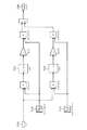
以下、本発明の第1実施形態について説明する。図1に、本発明の第1実施形態である装置システム全体の構成図を示す。なお、図11と同一要素のものについては同一符号を付して説明は省略する。
図1に示す制御装置500は、磁気軸受フィードバック制御手段を備えた従来の制御装置200に加えて、振動検出手段としての振動検出器503、振動抑制制御補償手段としての振動抑制制御補償器504及び加算手段としての加算器505を備えている。
【0071】
振動検出器503は、ターボ分子ポンプ本体100の各回転体位置センサ107,108,109から出力された変位信号を入力としている。
また、振動検出器503では、回転体103の変位のラプラス変換と所定の伝達関数とを乗算した第1の乗算結果と、回転体103に作用する不釣り合い力の変動分のラプラス変換と回転体103の質量の逆数とを乗算した第2の乗算結果とを加算した結果を時間領域に変換し、この変換結果を、装置固定部600の加速度信号として出力するようになっている。
【0072】
また、振動検出器503内には、伝達関数の算出のために必要なパラメータが予め決められており(あるいは予め測定されており)、図示しない記憶装置等に保存されている。そして、振動検出器503の出力信号は、装置固定部600の加速度として、振動抑制制御補償器504へ出力されている。
なお、装置固定部600とは、チャンバ300及びターボ分子ポンプ本体100のうち回転体103を除いた部分のことをいう。
【0073】
振動抑制制御補償器504は、振動検出器503から出力された加速度信号に、所定の周波数特性を持つ増幅率を掛け合わせてゲインを調節し、装置固定部600の発散又は発振を防止するために、位相補償を行うようになっている。
【0074】
加算器505には、補償器201の出力信号である位置制御力指令信号と、振動抑制制御補償器504の出力信号である加速度調節信号とが入力されている。そして、加算器505は、装置固定部600の振動を抑制できるように、加速度調節信号の正負(+−)の極性を反転させ、位置制御力指令信号に加算するようになっている。
【0075】
そして、加算器505の加算結果である制御力指令値は、電磁石制御手段としてのアンプ202に出力されるようになっている。この結果、アンプ202からは、電磁石104,105,106A,106Bを介して、回転体103に浮上支持力が作用されるようになっている。このとき、電磁石104,105,106A,106B(すなわち、装置固定部600)は浮上支持力の反力を受けるが、その反力には装置固定部600の振動を抑制する力が含まれているため、この力によって装置固定部600の振動が抑制されるようになっている。
【0076】
また、図1に示す装置システムは、図11に示す装置システムと異なり、ターボ分子ポンプ本体100とチャンバ300との間には、ポンプ固定部304が介設されている。
【0077】
このポンプ固定部304は、円筒状の固定柱305を備えており、ターボ分子ポンプ本体100をチャンバ300に固定するものである。
このとき、固定柱305は、その一端が、図示しないフランジを介してチャンバ300に締結固定され、その他端は、フランジ303を介してターボ分子ポンプ本体100の吸気口101と締結固定されている。
【0078】
次に、第1実施形態である装置システムの作用について説明する。
まず、装置固定部600の加速度を導出する方法について説明する。この加速度の導出方法を説明するにあたり、装置システム全体のブロック図を図2に示す。なお、図1と同一要素のものについては同一符号を付して説明は省略する。
【0079】
図2に示す装置用ダンパ401は、その機能を、ばね定数ksを有する弾性体401aと、粘性係数csを有する粘性抵抗401bとでモデル化することができる。
また、ターボ分子ポンプ本体100の回転体103は、各電磁石104,105,106A,106Bにより浮上支持されている。
【0080】
この浮上支持の剛性は、ラプラス領域においては、径方向では、回転体103の装置固定部600に対する径方向変位のラプラス変換を入力とし、電磁石104,105から回転体103に作用する力の変動分のラプラス変換を出力とする伝達関数Fr(s)で表される。
【0081】
また、軸方向では、回転体103の装置固定部600に対する軸方向変位のラプラス変換を入力とし、電磁石106A,106Bから回転体103に作用する力の和の変動分のラプラス変換を出力とする伝達関数Fa(s)で表される。
従って、これらの伝達関数Fr(s),Fa(s)は、制御装置500の補償器201やアンプ202等から構成される磁気軸受フィードバック制御手段固有の伝達関数であるといえる。
【0082】
さらに、ターボ分子ポンプ本体100は、従来と異なり、チャンバ300に固定されているので、装置固定部600すなわちチャンバ300及びターボ分子ポンプ本体100のうち回転体103を除いた部分は一体として考えることができる。
以上により、床400と、装置固定部600と、回転体103との間の運動モデルは、径方向、軸方向ともに図3に示すようなモデルで表現することができる。
【0083】
図3において、変位xb(t)は、床400の絶対変位を表している。そして、変位xs(t)は、装置固定部600の絶対変位を示し、変位xr(t)は、回転体103の絶対変位を示している。
また、質量msは、装置固定部600の質量を表し、質量mrは、回転体103の質量を表している。
【0084】
さらに、外乱力bp(t)は、装置固定部600に作用する外乱力を示している。外乱力bp(t)としては、例えば、ターボ分子ポンプ本体100に接続されたドライポンプから伝わる振動等が考えられる。
【0085】
また、不釣り合い力ub(t)は、回転体103の形状中心軸と慣性中心軸の位置ずれに起因して発生する不釣り合い力を示す。
【0086】
ここで、装置固定部600に対する回転体103の相対変位を相対変位y(t)とおくと、この相対変位y(t)は、数1のように定義される。
【0087】
【数1】
![]()
さらに、図2において、回転体103が、装置固定部600から浮上支持されていることを、相対変位y(t)と、電磁石104,105又は電磁石106A,106Bが回転体103に作用する力との関係として、関数fを定義すると、回転体103の運動方程式は数2のように表現される。
【0089】
【数2】
![]()
また、数2は数1を導入することにより数3のように表される。
【0091】
【数3】
![]()
ここで、f(y(t))はy(t)の線形方程式で表されるので、初期値を0として数3をラプラス変換すると、数4が得られる。なおsはラプラス演算子である。
【0093】
【数4】

数4の左辺はラプラス領域における装置固定部600の加速度を表し、数4の両辺を時間領域に変換することで、装置固定部600の加速度を求めることができる。
【0095】
ここで、相対変位y(t)は、各回転体位置センサ107,108,109によって検出され、不釣り合い力ub(t)は、例えば「不釣り合い補償機能を備えた磁気軸受制御系の構成」(水野・樋口 計測自動制御学会論文集,20,12,p1095)や「弾性ロータのフィードフォワード形不釣り合い力相殺制御」(日本機械学会論文集(C編),56,528(1990)pp.2056−2064)に開示されているように、オブザーバを構成することにより、磁気軸受が回転体103を浮上支持する制御力と各回転体位置センサ107,108,109によって検出された回転体103の変位から推定することができる。
【0096】
なお、これらの例は、オブザーバにより回転体103に作用する不釣り合い力を推定し、フィードフォワード制御により回転体103に作用する不釣り合い力を相殺することで、回転体103の振動を抑制しようとするものであるが、本発明は、数4又は後述する数5を時間領域に変換した結果に基づく計算により、装置固定部600の加速度を求め、この加速度を抑制するように制御するものであって、これらの例とは制御対象と制御方法が異なる。また、これらの例は回転体103の振動を抑制するのに対し、本発明は、敢えて回転体103を振動させ、その振動によって装置固定部600に作用する力を利用して、装置固定部600の振動を抑制するものである。
【0097】
また、数4又は数5から明らかなように、装置固定部600の加速度は、装置固定部600側の状態にはよらず、ターボ分子ポンプ本体100側に存在するパラメータと、各回転体位置センサ107,108,109の検出した変位信号から求められる。
【0098】
次に、算出した装置固定部600の加速度に基づいて、装置固定部600の振動を抑制するための動作を説明する。
制御装置500の振動検出器503は、数4の両辺を時間領域に変換した結果の計算を行うことにより、装置固定部600の加速度を求め、この加速度の信号を出力する。
【0099】
この信号は、振動抑制制御補償器504に入力され、ここで補償器201の出力へ加算する際のゲインが調節される。また、振動抑制制御補償器504では、制御装置500と振動抑制制御補償器504とターボ分子ポンプ本体100とがフィードバック制御系を構成しているため、装置固定部600が発散又は発振しないように、加速度信号に対して、位相補償等の対策を取る。
【0100】
そして、振動抑制制御補償器504から出力された加速度調節信号は、加算器505に送られ、ここで装置固定部600の振動を抑制するように正負(+−)の極性を反転して、補償器201の出力である位置制御力指令信号へ加算される。
【0101】
この加算結果である制御力指令値は、アンプ202に出力され、アンプ202は、加算器505からの制御力指令値に基づいて、電磁石104,105,106A,106Bを励磁し回転体103を浮上支持する。このとき、電磁石104,105,106A,106B(すなわち、装置固定部600)は、回転体103に作用させる浮上支持力の反力を受けるが、この反力には装置固定部600の振動を抑制する力が含まれているため、この力によって装置固定部600の振動が抑制される。
このように、装置固定部600の加速度に対して、この加速度を抑制する力を、電磁石104,105,106A,106Bに作用する浮上支持力の反力に発生させることで、装置固定部600の振動を抑制することができる。
【0102】
以上により、ターボ分子ポンプ本体100及び制御装置500は、装置システム全体の振動を抑制することが可能である。
【0103】
そして、この振動抑制は、チャンバ300に新たな振動検出センサ等を設置することなく、各回転体位置センサ107,108,109の変位信号とターボ分子ポンプ本体100側のパラメータのみを利用して達成することができる。
よって、新たなセンサを配設することなく、真空ポンプの被対象設備を含めた装置システム全体の低振動化を実現することが可能である。
【0104】
なお、本実施形態においては、振動検出器503は、数4を時間領域に変換した結果の計算を行うことにより装置固定部600の加速度を求めるとして説明してきたが、これに限られるものではない。
すなわち、回転体103に作用する不釣り合い力ub(t)が装置固定部600の加速度に及ぼす影響を無視する場合には、回転体103の変位のラプラス変換と所定の伝達関数とを乗算した乗算結果を時間領域に変換した変換結果、例えば、以下に示す数5の両辺を時間領域に変換した結果の計算を行うことにより装置固定部600の加速度を求めても良い。
【0105】
【数5】
また、本実施形態においては、振動抑制制御補償器504は、振動検出器503の出力信号にゲイン調整と位相補償を施すように構成したが、これに限られるものではなく、PID制御補償器、又は、最適制御補償器、H∞制御補償器、スライディングモード制御補償器等のその他の方式の補償器であっても良いし、これらの補償器のいずれか少なくとも二つを組み合わせて構成しても良い。また、補償器201の制御対象である回転体103の変位と、振動抑制制御補償器504の制御対象である装置固定部600の加速度が発散又は発振しなければ、振動抑制制御補償器504を備えなくても良い。
【0107】
さらに、本実施形態において、加算器505は、補償器201の出力信号に振動抑制制御補償器504が出力する加速度調節信号を正負(+−)の極性を反転して加算し、その加算結果である制御力指令値をアンプ202に出力するとして説明してきたが、これに限られるものではない。加算器505は、制御装置500のフィードバック制御ループ上の伝達信号であれば、どの信号に加算しても良い。
【0108】
例えば、加算器505は、各回転体位置センサ107,108,109と補償器201との間に接続されて、各回転体位置センサ107,108,109の変位信号に、振動抑制制御補償器504が出力する加速度調整信号を正負(+−)の極性を反転して加算し、その加算結果を補償器201に出力しても良い。このとき、振動抑制制御補償器504は、加算器505によって加速度調整信号が正負(+−)の極性を反転して加算されるフィードバック制御ループ上の伝達信号に応じた制御補償を行う。
【0109】
また、上述のように、加算器505を各回転体位置センサ107,108,109と補償器201との間に接続した場合、通常、補償器201は、信号のゲイン調整やその位相補償、PID制御補償、又は、最適制御補償、H∞制御補償、スライディングモード制御補償等のその他の制御補償を行うための機能を備えている。このため、振動抑制制御補償器504が行っていた機能を補償器201内に容易に組み込むことができる。
【0110】
さらに、本実施形態は、いわゆる5軸制御の磁気軸受に用いられる場合に限られず、3軸、1軸制御の磁気軸受に対して用いても良い。例えば1軸制御の場合、制御機能を有する電磁石も1軸分しか存在しないので、装置固定部600が振動したときに、その振動を抑制する力を作用させることができる方向が、その電磁石で制御できる1方向となる。
【0111】
また、本実施形態では、装置固定部600の加速度を算出することで、装置固定部600の振動を抑制していたが、これを装置固定部600の加加速度、速度、位置等のように加速度を所要回数だけ微分又は積分した結果に相当する物理量を算出することで達成しても良い。
【0112】
次に、本発明の第2実施形態について説明する。
第1実施形態である装置システムでは、電磁石104,105又は電磁石106A,106Bが回転体103に作用する力を求めるに際し、伝達関数Fr(s),Fa(s)を計算していたが、本実施形態である装置システムでは、伝達関数Fr(s),Fa(s)の計算を行う代わりに、加算器505から出力された制御力指令値等を用いるものである。
【0113】
図4に、本発明の第2実施形態である装置システム全体の構成図を示す。なお、図1と同一要素のものについては同一符号を付して説明は省略する。
図4に示す制御装置550は、第1実施形態の振動検出器503に代えて、振動検出手段及びモータ制御手段としての振動検出/モータ制御器553を備えている。
【0114】
この振動検出/モータ制御器553には、加算器505の出力である制御力指令値が入力されるようになっている。そして、振動検出/モータ制御器553では、装置固定部600の加速度を求める際に、この制御力指令値を使用するようになっている。
【0115】
また、本実施形態のターボ分子ポンプ本体150では、第1実施形態で用いられていた永久磁石を有するモータ121の代わりに、誘導モータ171が使用されている。そして、この誘導モータ171には、振動検出/モータ制御器553から無通電信号が出力されており、誘導モータ171は、振動検出/モータ制御器553で装置固定部600の加速度の算出が行われる期間中、無通電状態(フリーラン)とされるようになっている。
【0116】
さらに、振動検出/モータ制御器553には、回転体103に作用する不釣り合い力ub(t)による誤差を低減するための回転周波数追従型ノッチフィルタ806が設けられている(詳細は後述する)。
【0117】
なお、本実施形態の振動検出/モータ制御器553には、加算器505から出力される制御力指令値の代わりに、回転体103と、電磁石104,105又は電磁石106A,106Bとの間に発生する磁束の変動量を示す磁束検出信号が入力されても良い。そして、この磁束の変動量に基づいて、装置固定部600の加速度を求めても良い。
【0118】
この場合には図5に示すように、ターボ分子ポンプ本体150に、回転体103と電磁石104,105又は電磁石106A,106Bとの間に発生する磁束の変動量を検出する磁束検出器181を設け、この検出結果を振動検出/モータ制御器553に出力するようにすれば良い。
【0119】
次に、第2実施形態である装置システムの作用について説明する。
まず、装置固定部600の加速度を導出する方法について説明する。
この加速度の導出方法を説明するにあたり、装置システム全体のブロック図は、第1実施形態で説明した図2と同様である。そして、このブロック図に基づいて運動モデルを構成すると、図6のようになる。
【0120】
このとき、図6において、第1実施形態である運動モデル(図3)との対比を行うと以下のようになる。
まず、第1実施形態である運動モデルでは、相対変位y(t)と、電磁石104,105又は電磁石106A,106Bが回転体103に作用させる力との関係として関数fr,faを定義していたが、本実施形態ではこれらの関数fr,faは定義されていない。その代わりに、本実施形態では電磁石104,105又は電磁石106A,106Bが回転体103に及ぼす力として、磁気軸受の浮上力の調整量fmb(t)そのものが定義されている。
【0121】
また、第1実施形態である運動モデルでは考慮されていなかったが、本実施形態の運動モデルでは、誘導モータ171が回転体103に及ぼす力としてモータ力fmt(t)が考慮されている。
【0122】
通常、第1実施形態のターボ分子ポンプ本体100であっても、モータ121の回転子側である永久磁石のS極とN極がロータ軸113の軸心を挟んで対向配置され、かつ固定子側である電磁石がロータ軸113の軸心を挟んで対向配置されていれば、回転体103には回転させるトルク成分のみが生じて、永久磁石の磁極とモータ121の電磁石との間に作用する力は、全て相殺されて0になる。従って、この場合にはモータ力fmt(t)を考慮する必要はない。
【0123】
しかしながら、実際には永久磁石の磁束の誤差や、固定子側の電磁石に対するロータ軸113の偏心等が起こり得る。そのため、これらの原因によりモータ力fmt(t)はゼロにならない。従って、装置固定部600の加速度の算出における誤差を小さくするためには、このモータ力fmt(t)の影響を考慮することが望ましい。
【0124】
さらに、本実施形態の運動モデルでは、不釣り合い力ub(t)は角速度が回転体103の回転角速度ωと等しい正弦波に近似される(以下、不釣り合い力ub(ωt)と示す)。この不釣り合い力ub(ωt)は、上述したように回転体103の形状中心軸と慣性中心軸の位置ずれに起因して発生する不釣り合い力であるため、このように角速度ωの正弦波に近似することが可能となっている。
【0125】
そこで、回転体103が装置固定部600から浮上支持されていることについて、回転体103の運動方程式を求めると数6のようになる。
【0126】
【数6】
![]()
また、数6は、数1で定義した相対変位y(t)を導入することにより数7のように表される。
【0128】
【数7】
![]()
さらに、数7は若干の変形を加えることで数8のように表される。
【0130】
【数8】
![]()
ここで、数8に示された磁気軸受の浮上力の調整量fmb(t)、モータ力fmt(t)、不釣り合い力ub(ωt)について考察する。
まず、磁気軸受の浮上力の調整量fmb(t)について考察する。
上述したように、第1実施形態では相対変位y(t)と、電磁石104,105又は電磁石106A,106Bが回転体103に作用させる力との関係として、関数fr,faを定義していた。そして、この関数fr,faをラプラス領域に変換し、伝達関数Fr(s),Fa(s)等からラプラス領域における装置固定部600の加速度を求め、さらにこれを時間領域に変換することで、装置固定部600の加速度を求めていた。
【0132】
しかしながら、伝達関数Fr(s),Fa(s)の算出のために必要なパラメータは予め決められるか、測定される必要があり、かつこれらを振動検出器503内に記憶しておく必要があった。また、伝達関数Fr(s),Fa(s)の演算はそれ自体複雑であるため、高速な演算器が必要であった。
【0133】
これに対し、本実施形態では、伝達関数Fr(s),Fa(s)の計算を行う代わりに、磁気軸受の浮上力の調整量fmb(t)そのものを定義し、この浮上力の調整量fmb(t)として加算器505から出力された制御力指令値を使用している。そのため、装置固定部600の加速度の算出にあたり、既知となる制御力指令値を用いているので、安価な演算器でも十分に使用に耐えられる。
【0134】
ところで、このように制御力指令値を磁気軸受の浮上力の調整量fmb(t)とみなして演算を行う場合、この制御力指令値と実際の浮上力の調整量fmb(t)との間の誤差が問題となり得る。しかしながら、ロータ軸113に対して直角な平面上において、電磁石を回転体103を挟んで対向配置し、制御装置550として、電磁石104,105又は電磁石106A,106Bから発生される磁束の変動量が加算器505から出力される制御力指令値に高速に追従するような高ゲイン磁束フィードバック制御器を使用することで、かかる問題は解消される。
【0135】
この高ゲイン磁束フィードバック制御器のブロック線図を図7に示す。図7において、Fr(s)は、制御力指令値fr(t)の変動分のラプラス変換である。また、Vm(s)は、磁束指令値vm(t)の変動分のラプラス変換であり、Im(s)は、電磁石電流値Im(t)の変動分のラプラス変換であり、φm(s)は、電磁石の磁束φm(t)の変動分のラプラス変換である。さらに、Fmb(s)は、電磁石の制御力fmb(t)の変動分のラプラス変換であり、X(s)は、電磁石と回転体の隙間の変動分のラプラス変換である。また、Rは、電磁石のコイルの抵抗であり、Lは、電磁石のインダクタンスである。
【0136】
ここに、ゲインK2を“L・s+R”と比較して非常に大きくすることで、磁束指令値vm(t)と、電磁石104,105又は電磁石106A,106Bから発生される制御磁束φm(t)は、一対一に対応するようになる。また、磁束φm(t)の変動分は、浮上力の調整量fmb(t)と比例関係を保ち、比例ゲインK1をこの比例定数K4の逆数とすれば、制御力指令値fr(t)は浮上力の調整量fmb(t)と一対一に対応するようになる。
以上により、制御力指令値と実際の浮上力の調整量fmb(t)との間の誤差を低減することが可能である。
【0137】
次に、モータ力fmt(t)について考察する。
上述したように、本実施形態においては装置固定部600の加速度の算出に際し、モータ力fmt(t)を考慮している。
しかしながら、このモータ力fmt(t)を正確に把握することは困難である。
【0138】
そこで、本実施形態では、永久磁石からなるモータ121の代わりに、誘導モータ171を使用している。そして、回転体位置センサ107,108,109が回転体103の位置を検出し、装置固定部600の加速度の算出を行う期間中は誘導モータ171を無通電状態とすることで、モータ力fmt(t)の影響をゼロにしている。この点、第1実施形態のように永久磁石からなるモータ121を用いた場合には、この永久磁石による磁束の影響をゼロにできないので、モータ力fmt(t)の影響を常に考慮する必要がある。
【0139】
なお、誘導モータ171を無通電状態とする期間は、以下のように決めることが望ましい。例えば、ターボ分子ポンプ本体150が電子顕微鏡等の設備に用いられる場合、電子顕微鏡により撮像が行われる時間、すなわち振動の抑制が最も望まれる期間は、数秒程度である。従って、誘導モータ171を無通電状態とする期間としては、数十秒〜1分程度の時間があれば十分である。
【0140】
一方、この期間中、回転体103に対しては誘導モータ171から回転力が与えられないため、回転体103の失速が問題となり得る。しかしながら、回転体103は慣性モーメントが大きいので、数十秒〜1分程度の時間では回転速度が大きく失速することはない。また、撮像を行うまでに十分にチャンバ300内のガス吸引が行われていると考えれば、この期間中のガス負荷による回転速度の低下もほとんど起こり得ない。従って、回転体103の位置を検出し、装置固定部600の加速度の算出を行う期間中に、誘導モータ171を無通電状態とすることによる不都合は考えられない。
【0141】
そこで、装置システムの振動抑制を行う期間中に誘導モータ171を無通電状態とすることで、数8中のモータ力fmt(t)をゼロとした式により、装置固定部600の加速度の算出が行われる。
【0142】
続いて、不釣り合い力ub(ωt)について考察する。
上述したように、不釣り合い力ub(ωt)は、オブザーバを構成することで、磁気軸受の浮上力の調整量と回転体位置センサが出力する回転体の変位の情報から推定することが可能である。
しかしながら、このようなオブザーバ理論に基づく計算は、複雑になるおそれがある。
【0143】
一方、不釣り合い力ub(ωt)は、回転体103の回転角速度ωを角速度とする正弦波に近似される。そのため、この不釣り合い力ub(ωt)をゼロと仮定して装置固定部600の加速度を算出しても、これによる演算誤差は、回転体103の回転角速度ωの周波数に限定され、その他の周波数帯域では装置固定部600の加速度を精度良く算出することができる。また、この不釣り合い力ub(ωt)による回転体103の振れも、回転角速度ωの周波数に限定されたものとなる。
【0144】
従って、上述したような誘導モータ171を無通電状態とした状態での装置固定部600の加速度の演算結果を、回転周波数追従型ノッチフィルタ806に通すことで、回転体103の回転角速度ωの周波数付近の演算結果を考慮しないようにすることができる。これにより、回転体103の回転角速度ωの周波数付近に不感帯が生じるものの、その他の周波数帯域では装置固定部600の加速度を精度良く算出することができる。
【0145】
ここで、回転周波数追従型ノッチフィルタ806の原理について詳細に説明する。
まず、回転体103の装置固定部600に対する振れxdは、フーリエ級数展開することで、数9のように表される。
【0146】
【数9】
但し、Rr(ωt)は回転体103の振れの回転体103の回転周波数成分(不釣り合い力ubにより生じる)、ωは回転体103の回転角速度、tは時間、Erは回転体103の振れの回転体103の回転周波数以外の周波数成分、Rs(ωt)は装置固定部600の変位の回転体103の回転周波数成分、Esは装置固定部600の変位の回転体103の回転周波数以外の周波数成分、ArはRr(ωt)の振幅、ψrはRr(ωt)の位相、AsはRs(ωt)の振幅、ψsはRs(ωt)の位相を表す。
【0148】
このとき、回転体103の装置固定部600に対する振れxdは、各回転体位置センサ107,108,109によって検出される。また、回転体103の回転角速度ωは、モータ121等に設けられた回転数センサ等によって検出される。
【0149】
そして、この回転体位置センサ107,108,109により検出された回転体103の検出信号xdに対し、以下のような演算処理を行う。
まず、検出信号xdに対し、sin(ωt),cos(ωt)を乗算することで、数10、数11を得る。
【0150】
【数10】
【数11】
また、数10、数11に対し三角関数の加法定理を導入することで、数12、数13を得る。
【0153】
【数12】
【数13】
そして、数12、数13をカットオフ周波数の低いローパスフィルタに通すとAC成分が除去されて、数14、数15を得る。
【0156】
【数14】
![]()
【数15】
![]()
さらに、数14、数15のar,brのそれぞれにsin(ωt),cos(ωt)を乗算して加算し、かつ2倍に増幅することで、数16のように回転体103の装置固定部600に対する振れの回転体103の回転周波数成分Rr(ωt)−Rs(ωt)が得られる。
【0159】
【数16】
さらに、回転体位置センサ107,108,109による回転体103の検出信号xdから、数16の回転周波数成分Rr(ωt)−Rs(ωt)を減算することで、数17のように結果信号xoを得る。
【0161】
【数17】
そして、数17の結果信号xoを制御装置550の補償器201に出力することで、補償器201では、回転体103の装置固定部600に対する振れの回転体103の回転周波数以外の周波数成分Er−Esのみが認識される。
【0163】
ここで、以上で説明した回転周波数追従型ノッチフィルタ806の原理を表したブロック図を図8に示す。
図8において、入力701が数10、数11中の検出信号xdに対応する。また、サイン波702、コサイン波703が数10、数11で乗算されたsin(ωt),cos(ωt)に対応する。そして、ローパスフィルタ704、705が数12、数13を通すローパスフィルタに対応する。その結果、図8の出力706は数16で計算される回転体103の装置固定部600に対する変位の回転周波数成分Rr(ωt)−Rs(ωt)に対応するようになる。そして、入力701からこの出力706を減算することで(図示略)、数17の結果信号xoが得られる。
【0164】
そこで、以上のような磁気軸受の浮上力の調整量fmb(t)、モータ力fmt(t)、不釣り合い力ub(ωt)についての考察結果に基づき、装置固定部600の加速度の算出を行う数8は、数18のように簡略化される。
【0165】
【数18】
![]()
一方、数18は、初期値が0であるとすれば、ラプラス領域では数19のように表される。
【0167】
【数19】
![]()
ここで、数19の右辺第2項のY(s)にはラプラス演算子sの二乗の係数が掛かっている。そのため、数19はプロパーな式ではなく(すなわち、分子のラプラス演算子sの次数が分母のラプラス演算子sの次数よりも大きく)、数18からも明らかなように、この計算には相対変位y(t)を2階微分するための2次の微分器が必要となる。
【0169】
そして、演算の過程において微分器を必要とすると、周波数が高くなるに連れて高ゲインとなり、この演算結果を振動抑制制御補償器にフィードバック入力し、装置固定部600の振動を抑制しようとすれば、そのフィードバック制御系の安定性が損なわれるおそれがある。また、一般にノイズは高周波数帯域に生じる場合が多く、この微分器によりノイズが増幅される傾向にもある。
そのため、数19を厳密にプロパーな式(すなわち、分子のラプラス演算子sの次数が分母のラプラス演算子sの次数よりも小さい式)にすることが望ましい。そこで、数19の演算結果を2次のローパスフィルタに通すと、数20が得られる。なおζ,ωcは所定の定数である。
【0170】
【数20】
さらに、数20に変形を加えると数21が得られる。
【0172】
【数21】
数21の右辺は全ての項について厳密にプロパーな式であり、この数21を、装置固定部600の加速度の算出に用いることで、振動抑制のためのフィードバック制御系の安定性を向上させることができ、かつノイズを低減することができる。
【0174】
なお、以上のような装置固定部600の加速度の算出方法を表したブロック図を図9に示す。
図9において、入力801が数21中の相対変位y(t)のラプラス変換Y(s)に対応する。また、入力802が数21中の磁気軸受の浮上力の調整量fmb(t)のラプラス変換Fmb(s)に対応する。そして、ローパスフィルタ803は数21中の右辺第3、4項に掛かる係数であり、ローパスフィルタ804は右辺第1、2項に掛かる係数に対応する。従って、中間出力805が数21中の装置固定部600の加速度のラプラス変換s2Xs(s)に対応する。
さらに、この中間出力805を、上述で説明した回転周波数追従型ノッチフィルタ806に通すことで、図9の出力807は、数18で計算される装置固定部600の加速度のラプラス変換に対応するようになる。
【0175】
次に、算出した装置固定部600の加速度に基づいて、装置固定部600の振動を抑制するための動作を説明する。
本実施形態における振動抑制動作は、第1実施形態と同様であるが、振動検出/モータ制御器553から、誘導モータ171に対し無通電信号による制御が行われる点が異なっている。
【0176】
例えば、チャンバ300側から自動あるいは手動により、チャンバ300で電子顕微鏡による撮像等が行われる旨の信号が振動検出/モータ制御器553に入力されると(図示略)、この信号に基づき振動検出/モータ制御器553は誘導モータ171を無通電状態とする。
【0177】
そして、この誘導モータ171を無通電状態としている期間中、振動検出/モータ制御器553では装置固定部600の加速度の算出が行われ、加速度信号が振動抑制制御補償器504に出力される(以降は第1実施形態と同様である)。
これにより、装置固定部600の加速度に対して、この加速度を抑制する力を、電磁石104,105,106A,106Bに作用する浮上支持力の反力に発生させることができるので、装置固定部600の振動を抑制することができる。
【0178】
一方、チャンバ300側から、電子顕微鏡による撮像等が終了した旨の信号が振動検出/モータ制御器553に入力されると(図示略)、この信号に基づき振動検出/モータ制御器553は誘導モータ171を通電させる。
これにより、誘導モータ171から回転体103に回転力が与えられ、磁気軸受は、回転体103に対して、例えば従来と同様の位置制御を行う。
【0179】
以上により、伝達関数Fr(s),Fa(s)の計算を行う代わりに、磁気軸受の制御力指令値等を用いて装置固定部600の加速度の算出を行っているので、安価な演算器を用いても高精度に算出することが可能となる。
【0180】
また、数21のような厳密にプロパーな式に基づいて、装置固定部600の加速度を求めているので、振動抑制のフィードバック制御系の安定性を向上させることができ、かつノイズを低減することができる。
【0181】
なお、本実施形態においては、数21等において、装置固定部600の加速度を求めるとして説明してきたが、これに限られず、第1実施形態と同様に、装置固定部600の加加速度、速度、位置等のように加速度を所要回数だけ微分又は積分した結果に相当する物理量を算出するようにしても良い。
【0182】
また、本実施形態においては、ターボ分子ポンプ本体150がチャンバ300に固定されるものとして説明してきたが、これに限られるものではない。もちろん、装置固定部600側が完全な剛体であれば、以上で説明した通りの効果が得られるので最も望ましいが、チャンバ300等は完全な剛体であるとは限らないからである。
【0183】
チャンバ300の剛性が低い場合や、従来のようにターボ分子ポンプ本体150がポンプ用ダンパ301を介してチャンバ300に固定される構成であっても、各実施形態ではターボ分子ポンプ本体100,150を中心とした系の低振動化が行われるので、十分に装置システム全体の低振動化に寄与することが可能である。
【0184】
さらに、本実施形態においては、回転体位置センサ107,108,109の変位信号に基づいて、それぞれに対応する装置固定部600の加速度等を求め、各電磁石104,105,106A,106Bを制御するとして説明してきたが、これに限られない。
【0185】
一般に、回転体103の運動は、並進成分の運動と回転成分の運動とが複雑に混在し合っている。そして、従来から行われているように、上側径方向センサ107及び下側径方向センサ108等の検出結果から、回転体103の運動は、並進成分と回転成分とに分離することができる。従って、回転体103の並進成分と回転成分のそれぞれに対応して装置固定部600の加速度等を求めれば、装置固定部600の加速度等の並進成分と回転成分を求めることができる。
【0186】
具体的には、以下のような計算を行う。まず、並進成分に対応した装置固定部600の加速度等を求める場合には、回転体103の変位の並進成分を、数8の相対変位y(t)に代入して計算を行う。一方、回転成分に対応した装置固定部600の加速度等を求める場合には、回転体103の変位の回転成分を、数8の相対変位y(t)に代入し、回転体103のその回転中心軸まわりの慣性モーメントを、数8の質量mrに代入して計算を行う。
そして、これらの算出結果である並進成分と回転成分に対応した装置固定部600の加速度等から、再び上側径方向電磁石104及び下側径方向電磁石105に対する制御力指令値等を求めることで、電磁石104,105を制御すれば良い。
【0187】
【発明の効果】
以上説明したように本発明によれば、磁気軸受装置は、振動検出手段と加算手段と振動抑制制御手段とを備えて構成したことから、新たな振動センサを配設することなく、真空ポンプの被対象設備を含めた装置システム全体の低振動化を実現することが可能である。
また、磁気軸受装置は、振動検出手段を備えて構成したことから、新たな振動センサを配設することなく、真空ポンプの被対象設備を含めた装置システム全体の振動検出を実現することが可能である。
【図面の簡単な説明】
【図1】 本発明の第1実施形態である装置システム全体の構成図
【図2】 装置システム全体のブロック図
【図3】 装置システム全体の運動モデルを示した図
【図4】 本発明の第2実施形態である装置システム全体の構成図
【図5】 同上(別例)
【図6】 装置システム全体の運動モデルを示した図
【図7】 高ゲイン磁束フィードバック制御器のブロック線図
【図8】 回転周波数追従型ノッチフィルタの原理を表したブロック図
【図9】 装置固定部の加速度の算出方法を表したブロック図
【図10】 従来のターボ分子ポンプの縦断面図
【図11】 従来の装置システム全体の構成図
【符号の説明】
100,150 ターボ分子ポンプ本体
103 回転体
104 上側径方向電磁石
105 下側径方向電磁石
106A,106B 軸方向電磁石
107 上側径方向センサ
108 下側径方向センサ
109 軸方向センサ
171 誘導モータ
181 磁束検出器
200,500,550 制御装置
201 補償器
202 アンプ
300 チャンバ
301 ポンプ用ダンパ
400 床
401 装置用ダンパ
503 振動検出器
504 振動抑制制御補償器
505 加算器
553 振動検出/モータ制御器
600 装置固定部
806 回転周波数追従型ノッチフィルタ[0001]
BACKGROUND OF THE INVENTION
The present invention relates to a magnetic bearing device having a vibration suppressing function, a magnetic bearing device having a vibration estimating function, and a pump device equipped with the magnetic bearing device, and particularly to a target of a vacuum pump without providing a new vibration sensor. The present invention relates to a magnetic bearing device having a vibration suppressing function capable of realizing a reduction in vibration of the entire apparatus system including equipment, a magnetic bearing device having a vibration estimating function, and a pump device equipped with the magnetic bearing device.
[0002]
[Prior art]
With the recent development of electronics, the demand for semiconductors such as memories and integrated circuits is increasing rapidly.
These semiconductors are manufactured by doping impurities into a highly pure semiconductor substrate to impart electrical properties, forming a fine circuit pattern on the semiconductor substrate, and laminating them.
[0003]
These operations need to be performed in a high vacuum chamber in order to avoid the influence of dust in the air. A vacuum pump is generally used for evacuating the chamber, but a turbo molecular pump, which is one of the vacuum pumps, is often used because it has a small residual gas and is easy to maintain.
[0004]
Also, in the semiconductor manufacturing process, there are many processes in which various process gases are applied to the semiconductor substrate. The turbo molecular pump not only evacuates the chamber, but also exhausts these process gases from the chamber. Also used.
[0005]
Furthermore, turbo molecular pumps are also used in equipment such as electron microscopes to prevent the refraction of the electron beam due to the presence of dust, etc., so that the environment in the chamber of the electron microscope or the like is brought into a highly vacuum state. Yes.
[0006]
Such a turbo molecular pump includes a turbo molecular pump main body for sucking and exhausting gas from a chamber of a semiconductor manufacturing apparatus, an electron microscope, or the like, and a control device for controlling the turbo molecular pump main body.
[0007]
Here, a longitudinal sectional view of the turbo molecular pump main body is shown in FIG. 10, and a configuration diagram of the entire apparatus system when this turbo molecular pump main body is used for evacuation in the chamber is shown in FIG.
In FIG. 10, the turbo molecular pump
[0008]
A
[0009]
The upper
[0010]
The
The
[0011]
Further, the lower
[0012]
Furthermore,
[0013]
The
[0014]
As described above, in the
[0015]
The
Further, a rotation speed sensor and a motor temperature sensor (not shown) are attached to the
[0016]
A plurality of
[0017]
Similarly, the fixed blades 123 are also formed to be inclined at a predetermined angle from a plane perpendicular to the axis of the
And one end of the fixed wing | blade 123 is supported in the state inserted and inserted between the several fixed wing |
[0018]
The fixed blade spacer 125 is a ring-shaped member and is made of a metal such as a metal such as aluminum, iron, stainless steel, or copper, or an alloy containing these metals as components.
An
[0019]
An
[0020]
The threaded
The direction of the spiral of the
[0021]
A
[0022]
The
[0023]
In addition, a
[0024]
In this configuration, when the rotating blade 102 is driven and rotated by the
[0025]
Exhaust gas sucked from the
[0026]
In addition, the exhaust gas sucked from the
[0027]
For this reason, a pipe (not shown) is provided in the
[0028]
Here, the turbo-molecular pump
[0029]
The
[0030]
By the way, the turbo molecular pump
That is, if vibration occurs during the exposure of the circuit pattern in the
Further, in the
[0031]
Therefore, as shown in FIG. 11, the turbo molecular pump
A
[0032]
The
Similarly to the
[0033]
In such a configuration, even if vibration is generated from the turbo molecular pump
The same applies to the vibration generated from the
As described above, the vibration of the
[0034]
However, in the case of vibration isolation using such a mechanical damper, it is difficult to obtain a good vibration isolation effect particularly in a low frequency band with respect to vibration transmitted through the turbo molecular pump
[0035]
Therefore, a plurality of
[0036]
Further, with the recent expansion of the volume of the
[0037]
Such an increase in the size of the
[0038]
Further, a dry pump (not shown) is connected to the turbo molecular pump
[0039]
Such vibration of the
[0040]
In order to solve such a problem,
[Patent Document 1]
JP 2002-147454 A
[0041]
[Problems to be solved by the invention]
However, in the case of
[0042]
In addition, since the vibration detection sensor is disposed on the
[0043]
The present invention has been made in view of such a conventional problem, and it is possible to realize low vibration of the entire apparatus system including the target equipment of the vacuum pump without particularly arranging a new vibration sensor. It is an object of the present invention to provide a magnetic bearing device having a possible vibration suppressing function, a magnetic bearing device having a vibration estimating function, and a pump device equipped with the magnetic bearing device.
[0044]
[Means for Solving the Problems]
Therefore, the present invention relates to a magnetic bearing device having a vibration suppressing function, a rotating body, an electromagnet that causes a floating force to act on the rotating body, a stator portion on which the electromagnet is fixed, and the stator portion of the rotating body. Displacement detecting means for detecting a relative displacement in the radial direction and / or axial direction with respect to the magnetic bearing, a magnetic bearing control compensator for calculating an adjustment amount of the levitation force based on the relative displacement detected by the displacement detecting means, and the magnetic bearing Electromagnet control means for adjusting the levitation force according to the calculation result of the adjustment amount of the levitation force by the control compensator, and vibration detection means for detecting a predetermined physical quantity of the device fixing portion whose relative position to the stator portion is fixed And the output of the vibration detection means, the polarity of the output being inverted, and a magnetic bearing feed comprising at least the displacement detection means, the magnetic bearing control compensator, and the electromagnet control means. Adding means for adding to the transmission signal of the control means, and the predetermined physical quantity includes acceleration of the device fixing portion and / or the stator portion, displacement, speed and acceleration obtained by differentiating or integrating the acceleration a required number of times. At least one of acceleration and the like, and the acceleration is obtained by multiplying a first multiplication result obtained by multiplying a Laplace transform of the relative displacement of the rotating body detected by the displacement detection unit and a predetermined transfer function in a time domain. The result is a converted result.
[0045]
The vibration detecting unit detects a predetermined physical quantity of the device fixing unit and / or the stator unit, and outputs this to the adding unit. The adding means inverts the polarity of the signal output from the vibration detecting means and adds it to the output of the magnetic bearing feedback control means.
Thereby, the magnetic bearing device can be provided with a vibration suppressing function.
The Laplace transform of the displacement of the rotating body refers to Y (s) in
[0046]
The present invention also relates to a magnetic bearing device having a vibration suppressing function, comprising unbalanced force detecting means for detecting or estimating an unbalanced force acting on the rotating body, wherein the acceleration is the first multiplication result, The addition result obtained by adding the second multiplication result obtained by multiplying the Laplace transform of the fluctuation of the unbalance force acting on the rotating body detected or estimated by the unbalance force detecting means and the inverse of the mass of the rotating body. It is a conversion result obtained by converting into a time domain.
[0047]
Accordingly, the magnetic bearing device can further include a vibration suppression function that suppresses vibrations generated in the device fixing portion and / or the stator portion due to the unbalanced force acting on the rotating body.
Note that the Laplace transform for fluctuations in the unbalance force is the U in equation (4). b (S).
[0048]
Furthermore, the present invention relates to a magnetic bearing device having a vibration suppressing function, wherein the predetermined transfer function is a relationship between a relative displacement of the rotating body and a force acting between the electromagnet and the rotating body due to the relative displacement. It is expressed by the transfer function specific to the magnetic bearing feedback control means and the mass of the rotating body.
[0049]
The predetermined transfer function is a function defined by the mass of the rotating body and the transfer function unique to the magnetic bearing feedback control means. Here, the transfer function specific to the magnetic bearing feedback control means is a function determined at the design stage of the magnetic bearing.
As a result, a predetermined transfer function can be calculated only with parameters in the magnetic bearing device without providing a new vibration sensor.
Note that the transfer function specific to the magnetic bearing feedback control means refers to F (s) in
[0050]
Furthermore, the present invention relates to a magnetic bearing device having a vibration suppressing function, a rotating body, an electromagnet that causes a floating force to act on the rotating body, a stator portion on which the electromagnet is fixed, and the stator portion of the rotating body. Displacement detecting means for detecting a relative displacement in the radial direction and / or axial direction with respect to the magnetic bearing, a magnetic bearing control compensator for calculating an adjustment amount of the levitation force based on the relative displacement detected by the displacement detecting means, and the magnetic bearing Vibration detection that detects a predetermined physical quantity of an electromagnet control unit that adjusts the levitation force in accordance with a calculation result of the adjustment amount of the levitation force by a control compensator, and a device fixing unit whose relative position to the stator unit is fixed And a magnetic bearing fee constituted by at least the displacement detecting means, the magnetic bearing control compensator, and the electromagnet control means. Adding means for adding to the transmission signal of the back control means, and the predetermined physical quantity includes acceleration of the device fixing part and / or the stator part, displacement, speed and jerk obtained by differentiating or integrating the acceleration a required number of times. The acceleration is obtained by multiplying the calculation result of the adjustment amount of the levitation force by the magnetic bearing control compensator or the addition result by the adding means and the inverse of the mass of the rotating body. It is a subtraction result obtained by subtracting a result of second-order differentiation of the relative displacement of the rotating body detected by the displacement detection means from a third multiplication result.
[0051]
When the adding means adds the output of the vibration detecting means with its polarity reversed to the calculation result of the adjustment amount of the levitation force by the magnetic bearing control compensator, the acceleration is the adding means. The subtraction result is obtained by subtracting the result of second-order differentiation of the relative displacement of the rotating body detected by the displacement detecting unit from the third multiplication result obtained by multiplying the addition result by the reciprocal of the mass of the rotating body. .
[0052]
Unlike the first aspect, the transfer function is not calculated when detecting the acceleration or the like of the device fixing portion and / or the stator portion. Instead, the levitation force itself that the electromagnet acts on the rotating body is used. As the levitation force, the calculation result of the adjustment amount of the levitation force by the magnetic bearing control compensator or the addition result added by the adding means is used.
As a result, the calculation result of the adjustment amount of the levitation force by the magnetic bearing control compensator or the addition result by the addition means, which is known for detecting the acceleration of the device fixing portion and / or the stator portion, is used, so that the calculation is inexpensive. Even using the device, it is possible to calculate the acceleration of the device fixing portion and / or the stator portion with high accuracy.
[0053]
Furthermore, the present invention relates to a magnetic bearing device having a vibration suppressing function, comprising magnetic flux detection means for detecting a fluctuation amount of a magnetic flux generated between the electromagnet and the rotating body, and as the third multiplication result, the magnetic Instead of the calculation result of the adjustment amount of the levitation force by the bearing control compensator, a multiplication result using a value proportional to the fluctuation amount of the magnetic flux detected by the magnetic flux detection means is used.
[0054]
A value proportional to the fluctuation amount of the magnetic flux detected by the magnetic flux detection means is used as the adjustment amount of the levitation force that the electromagnet acts on the rotating body.
Thus, since the transfer function is not calculated, it is possible to calculate the acceleration and the like of the device fixing portion and / or the stator portion with high accuracy even using an inexpensive calculation device.
[0055]
Furthermore, the present invention relates to a magnetic bearing device having a vibration suppressing function, comprising: an induction motor that rotationally drives the rotating body; and a motor control unit that controls an energization state of the induction motor. When the physical quantity is detected, the motor control means makes the induction motor non-energized.
[0056]
Generally, when a motor uses a permanent magnet as a field means, it is difficult to accurately grasp the force exerted on the rotating body due to uncertain characteristic changes such as a demagnetization phenomenon of the permanent magnet.
However, by using an induction motor that does not have a permanent magnet as the motor, when the predetermined physical quantity is detected by the vibration detection means, the induction motor is de-energized and the influence of the force exerted on the rotating body by the induction motor is reduced to zero. can do.
Thereby, a predetermined physical quantity can be detected with high accuracy.
[0057]
Furthermore, the present invention relates to a magnetic bearing device having a vibration suppressing function, comprising a rotational frequency tracking type notch filter that tracks the rotational frequency of the rotating body and removes the frequency component, and the acceleration or the like is the subtraction result. Is a result of passing through the rotation frequency tracking notch filter.
[0058]
The unbalanced force acting on the rotating body is approximated to a sine wave whose frequency is the rotating frequency of the rotating body. Therefore, by providing a rotation frequency tracking type notch filter that follows the rotation frequency of the rotating body and removes this frequency component, the device fixing portion and / or the stator can be used without considering the result near the rotation frequency of the rotating body. The acceleration of the part can be detected.
As a result, although a dead zone is generated in the vicinity of the rotational frequency of the rotating body, in other frequency bands, it is possible to accurately calculate the acceleration and the like of the device fixing portion and / or the stator portion by removing the influence of the unbalanced force.
The rotation frequency is the number of rotations per second.
[0059]
Furthermore, the present invention relates to a magnetic bearing device having a vibration suppressing function, and includes a low-pass filter through which the acceleration and the like pass.
[0060]
By providing a low-pass filter through which acceleration and the like pass, it is possible to perform a strictly proper calculation in the Laplace region.
This eliminates the need for a differentiator in the process of calculation, so that it is possible to improve the stability of the feedback control system that performs vibration suppression control based on the acceleration of the device fixing portion and / or the stator portion, and noise. Can be reduced.
[0061]
Furthermore, the present invention relates to a magnetic bearing device having a vibration suppressing function, and applies at least one control compensation of gain adjustment and / or phase compensation, PID control, and other control compensation to the output of the vibration detecting means. A vibration suppression control compensation means is provided.
[0062]
The vibration suppression control compensation means may be a compensator that performs gain adjustment and / or phase compensation on the output signal of the vibration detection means, or a PID control compensator, or an optimal control compensator, an H∞ control compensator, Other types of control compensators such as a sliding mode control compensator may be used. Further, at least two of these compensators may be combined.
Thereby, it is possible to effectively suppress the vibration of the device fixing portion and / or the stator portion without diverging.
[0063]
Furthermore, the present invention relates to a magnetic bearing device having a vibration estimation function, a rotating body, an electromagnet that causes a floating force to act on the rotating body, a stator portion on which the electromagnet is fixed, and the stator portion of the rotating body. Displacement detecting means for detecting a relative displacement in the radial direction and / or axial direction with respect to the magnetic field, a magnetic bearing control compensator for calculating an adjustment amount of the levitation force based on the displacement detected by the displacement detecting means, and the magnetic bearing control Electromagnet control means for adjusting the levitation force corresponding to the calculation result of the adjustment amount of the levitation force by a compensator, and vibration detection means for detecting a predetermined physical quantity of the device fixing portion whose relative position to the stator portion is fixed And The predetermined physical quantity is at least one of an acceleration of the device fixing portion and / or the stator portion, a displacement obtained by differentiating or integrating the acceleration a required number of times, a velocity, a jerk, and the like. The first multiplication result obtained by multiplying the Laplace transform of the relative displacement of the rotating body detected by the displacement detection means and a predetermined transfer function is a conversion result obtained by converting the result into the time domain.
[0064]
Furthermore, the present invention relates to a magnetic bearing device having a vibration estimation function, a rotating body, an electromagnet that causes a floating force to act on the rotating body, a stator portion on which the electromagnet is fixed, and the stator portion of the rotating body. Displacement detecting means for detecting a relative displacement in the radial direction and / or axial direction with respect to the magnetic field, a magnetic bearing control compensator for calculating an adjustment amount of the levitation force based on the displacement detected by the displacement detecting means, and the magnetic bearing control Electromagnet control means for adjusting the levitation force corresponding to the calculation result of the adjustment amount of the levitation force by a compensator, and vibration detection means for detecting a predetermined physical quantity of the device fixing portion whose relative position to the stator portion is fixed And The predetermined physical quantity is at least one of an acceleration of the device fixing portion and / or the stator portion, a displacement obtained by differentiating or integrating the acceleration a required number of times, a velocity, a jerk, and the like. The calculation result of the adjustment amount of the levitation force by the magnetic bearing control compensator Fruit The subtraction result is obtained by subtracting the result of second-order differentiation of the relative displacement of the rotating body detected by the displacement detecting means from the third multiplication result obtained by multiplying the inverse of the mass of the rotating body. To do.
[0065]
Furthermore, the present invention relates to a magnetic bearing device having a vibration estimation function, comprising magnetic flux detection means for detecting a fluctuation amount of a magnetic flux generated between the electromagnet and the rotating body, and as the third multiplication result, the magnetic Instead of the calculation result of the adjustment amount of the levitation force by the bearing control compensator, a multiplication result using a value proportional to the fluctuation amount of the magnetic flux detected by the magnetic flux detection means is used.
[0066]
Furthermore, the present invention relates to a pump device having a vibration suppressing function, which is a vacuum pump equipped with a magnetic bearing device, and the vacuum pump is installed in the target facility and sucks a predetermined gas from the target facility. It is characterized by doing.
[0067]
The vacuum pump is installed in a target facility and is equipped with a magnetic bearing device having a vibration suppressing function.
This makes it possible to reduce the vibration of the pump device without providing a new vibration sensor.
[0068]
Furthermore, the present invention relates to a pump device having a vibration estimation function, which is a vacuum pump equipped with a magnetic bearing device, and the vacuum pump is installed in the target equipment and sucks a predetermined gas from the target equipment. It is characterized by doing.
[0069]
As a result, it is possible to realize vibration estimation of the pump device without providing a new vibration sensor.
[0070]
DETAILED DESCRIPTION OF THE INVENTION
Hereinafter, a first embodiment of the present invention will be described. FIG. 1 shows a configuration diagram of the entire apparatus system according to the first embodiment of the present invention. Note that the same elements as those in FIG.
A
[0071]
The
Further, in the
[0072]
In the
In addition, the apparatus fixing | fixed
[0073]
The vibration
[0074]
The
[0075]
The control force command value, which is the addition result of the
[0076]
The apparatus system shown in FIG. 1 is different from the apparatus system shown in FIG. 11 in that a
[0077]
The
At this time, one end of the fixed
[0078]
Next, the operation of the device system according to the first embodiment will be described.
First, a method for deriving the acceleration of the
[0079]
The
The
[0080]
In the Laplace region, the levitation support has a rigidity in the radial direction, in which the Laplace transform of the radial displacement of the
[0081]
Further, in the axial direction, the Laplace transform of the axial displacement of the
Therefore, these transfer functions F r (S), F a It can be said that (s) is a transfer function specific to the magnetic bearing feedback control means including the
[0082]
Furthermore, unlike the conventional case, the turbo molecular pump
As described above, the motion model between the
[0083]
In FIG. 3, the displacement x b (T) represents the absolute displacement of the
Mass m s Represents the mass of the
[0084]
Furthermore, disturbance force b p (T) shows the disturbance force acting on the
[0085]
Also, unbalanced force u b (T) indicates an unbalance force generated due to a positional shift between the shape center axis of the
[0086]
Here, when the relative displacement of the
[0087]
[Expression 1]
![]()
Further, in FIG. 2, the fact that the
[0089]
[Expression 2]
![]()
In addition,
[0091]
[Equation 3]
![]()
Here, since f (y (t)) is expressed by a linear equation of y (t),
[0093]
[Expression 4]
The left side of
[0095]
Here, the relative displacement y (t) is detected by each rotary
[0096]
In these examples, an unbalance force acting on the
[0097]
Further, as is clear from
[0098]
Next, an operation for suppressing vibration of the
The
[0099]
This signal is input to the vibration
[0100]
Then, the acceleration adjustment signal output from the vibration
[0101]
The control force command value that is the addition result is output to the
As described above, the force that suppresses the acceleration of the
[0102]
As described above, the turbo molecular pump
[0103]
This vibration suppression is achieved using only the displacement signals of the rotary
Therefore, it is possible to reduce the vibration of the entire apparatus system including the target equipment of the vacuum pump without providing a new sensor.
[0104]
In the present embodiment, the
That is, the unbalance force u acting on the
[0105]
[Equation 5]
In the present embodiment, the vibration
[0107]
Further, in the present embodiment, the
[0108]
For example, the
[0109]
In addition, as described above, when the
[0110]
Furthermore, the present embodiment is not limited to the case of being used for a so-called 5-axis control magnetic bearing, and may be used for a 3-axis, 1-axis control magnetic bearing. For example, in the case of uniaxial control, there is only one electromagnet having a control function, so when the
[0111]
Further, in the present embodiment, the vibration of the
[0112]
Next, a second embodiment of the present invention will be described.
In the apparatus system according to the first embodiment, when the
[0113]
FIG. 4 shows a configuration diagram of the entire apparatus system according to the second embodiment of the present invention. Note that the same elements as those in FIG. 1 are denoted by the same reference numerals and description thereof is omitted.
A
[0114]
The vibration detection /
[0115]
Further, in the turbo molecular pump
[0116]
Further, the vibration detection /
[0117]
The vibration detection /
[0118]
In this case, as shown in FIG. 5, the turbo molecular pump
[0119]
Next, the operation of the device system according to the second embodiment will be described.
First, a method for deriving the acceleration of the
In describing the acceleration derivation method, the block diagram of the entire apparatus system is the same as that of FIG. 2 described in the first embodiment. And if an exercise | movement model is comprised based on this block diagram, it will become like FIG.
[0120]
At this time, in FIG. 6, the comparison with the motion model (FIG. 3) according to the first embodiment is as follows.
First, in the motion model according to the first embodiment, the function f is expressed as a relationship between the relative displacement y (t) and the force applied to the
[0121]
Further, although not considered in the motion model according to the first embodiment, in the motion model according to the present embodiment, the motor force f as the force exerted by the
[0122]
Normally, even in the turbo molecular pump
[0123]
However, in reality, errors in the magnetic flux of the permanent magnet, eccentricity of the
[0124]
Furthermore, in the motion model of this embodiment, the unbalance force u b (T) is approximated to a sine wave whose angular velocity is equal to the rotational angular velocity ω of the rotating body 103 (hereinafter referred to as unbalanced force u). b (Denoted as (ωt)). This unbalanced force u b Since (ωt) is an unbalanced force generated due to the positional deviation between the shape center axis of the
[0125]
Therefore, the equation of motion of the
[0126]
[Formula 6]
![]()
In addition, Expression 6 is expressed as Expression 7 by introducing the relative displacement y (t) defined in
[0128]
[Expression 7]
![]()
Furthermore, Expression 7 is expressed as Expression 8 with some modifications.
[0130]
[Equation 8]
![]()
Here, the adjustment amount f of the levitation force of the magnetic bearing shown in Equation 8 mb (T), motor force f mt (T) Unbalance force u b Consider (ωt).
First, the adjustment amount f of the levitation force of the magnetic bearing mb Consider (t).
As described above, in the first embodiment, the function f is expressed as the relationship between the relative displacement y (t) and the force that the
[0132]
However, the transfer function F r (S), F a The parameters necessary for calculating (s) need to be determined in advance or measured and stored in the
[0133]
On the other hand, in this embodiment, the transfer function F r (S), F a Instead of calculating (s), the adjustment amount f of the levitation force of the magnetic bearing mb (T) defines itself, and the adjustment amount f of this levitation force mb The control force command value output from the
[0134]
By the way, in this way, the control force command value is converted into the adjustment amount f of the magnetic bearing levitation force. mb When calculating as (t), the control force command value and the actual levitation force adjustment amount f mb The error between (t) can be a problem. However, on the plane perpendicular to the
[0135]
A block diagram of this high gain magnetic flux feedback controller is shown in FIG. In FIG. 7, F r (S) is the control force command value f r This is the Laplace transform for the fluctuation of (t). Also, V m (S) is the magnetic flux command value v m Is the Laplace transform of the variation of (t), and I m (S) is the electromagnet current value I m Laplace transform for fluctuation of (t), φ m (S) is the magnetic flux φ of the electromagnet. m This is the Laplace transform for the fluctuation of (t). In addition, F mb (S) is the control force f of the electromagnet mb This is Laplace conversion corresponding to the fluctuation of (t), and X (s) is Laplace conversion corresponding to the fluctuation of the gap between the electromagnet and the rotating body. R is the resistance of the coil of the electromagnet, and L is the inductance of the electromagnet.
[0136]
Where gain K 2 Is made very large compared with “L · s + R”, so that the magnetic flux command value v m (T) and the control magnetic flux φ generated from the
Thus, the control force command value and the actual levitation force adjustment amount f mb It is possible to reduce the error between (t).
[0137]
Next, the motor force f mt Consider (t).
As described above, in the present embodiment, when calculating the acceleration of the
However, this motor force f mt It is difficult to accurately grasp (t).
[0138]
Therefore, in this embodiment, an
[0139]
It is desirable that the period during which the
[0140]
On the other hand, during this period, rotational force is not applied from the
[0141]
Therefore, by setting the
[0142]
Then, unbalanced force u b Consider (ωt).
As mentioned above, the unbalance force u b By configuring the observer, (ωt) can be estimated from the adjustment amount of the levitation force of the magnetic bearing and the information on the displacement of the rotating body output from the rotating body position sensor.
However, calculations based on such observer theory may be complicated.
[0143]
On the other hand, unbalanced force u b (Ωt) is approximated to a sine wave with the rotational angular velocity ω of the
[0144]
Therefore, by passing the calculation result of the acceleration of the
[0145]
Here, the principle of the rotation frequency tracking
First, the swing x of the
[0146]
[Equation 9]
However, R r (Ωt) is the rotational frequency component (unbalance force u) of the
[0148]
At this time, the swing x of the
[0149]
Then, the detection signal x of the
First, the detection signal x d On the other hand, by multiplying sin (ωt) and cos (ωt), Equations 10 and 11 are obtained.
[0150]
[Expression 10]
[Expression 11]
Further, by introducing the trigonometric function addition theorem to Equations 10 and 11, Equations 12 and 13 are obtained.
[0153]
[Expression 12]
[Formula 13]
Then, when Equations 12 and 13 are passed through a low-pass filter with a low cutoff frequency, the AC component is removed, and Equations 14 and 15 are obtained.
[0156]
[Expression 14]
![]()
[Expression 15]
![]()
Further, a in formulas 14 and 15 r , B r Is multiplied by sin (ωt) and cos (ωt) and added together, and amplified by a factor of two, so that the rotational frequency of the
[0159]
[Expression 16]
Further, the detection signal x of the
[0161]
[Expression 17]
Then, the result signal x of Equation 17 o Is output to the
[0163]
Here, FIG. 8 shows a block diagram showing the principle of the rotational frequency tracking
In FIG. 8, the
[0164]
Therefore, the adjustment amount f of the levitation force of the magnetic bearing as described above. mb (T), motor force f mt (T) Unbalance force u b Based on the result of consideration on (ωt), Equation 8 for calculating the acceleration of the
[0165]
[Formula 18]
![]()
On the other hand, if the initial value is 0, Expression 18 is expressed as Expression 19 in the Laplace area.
[0167]
[Equation 19]
![]()
Here, Y (s) in the second term on the right side of Equation 19 is multiplied by the square coefficient of the Laplace operator s. Therefore, Equation 19 is not a proper expression (that is, the order of the Laplace operator s in the numerator is larger than the order of the Laplace operator s in the denominator). A second-order differentiator for second-order differentiation of y (t) is required.
[0169]
If a differentiator is required in the calculation process, the gain becomes higher as the frequency becomes higher. If the calculation result is fed back to the vibration suppression control compensator to suppress the vibration of the
Therefore, it is desirable that Equation 19 be a strictly proper expression (that is, an expression in which the order of the Laplace operator s in the numerator is smaller than the order of the Laplace operator s in the denominator). Therefore, when the calculation result of Expression 19 is passed through a secondary low-pass filter, Expression 20 is obtained. Ζ, ω c Is a predetermined constant.
[0170]
[Expression 20]
Further, when the equation 20 is modified, the equation 21 is obtained.
[0172]
[Expression 21]
The right side of Equation 21 is a strictly proper equation for all terms, and by using Equation 21 for calculating the acceleration of
[0174]
FIG. 9 is a block diagram showing a method for calculating the acceleration of the
In FIG. 9, the
Further, the
[0175]
Next, an operation for suppressing vibration of the
The vibration suppression operation in the present embodiment is the same as that in the first embodiment, except that the vibration detection /
[0176]
For example, when a signal indicating that imaging by an electron microscope is performed in the
[0177]
During the period when the
As a result, the force for suppressing the acceleration of the
[0178]
On the other hand, when a signal indicating that imaging by the electron microscope has been completed is input from the
As a result, a rotational force is applied from the
[0179]
Thus, the transfer function F r (S), F a Instead of performing the calculation of (s), the acceleration of the
[0180]
Further, since the acceleration of the
[0181]
In the present embodiment, the description has been given with respect to the acceleration of the
[0182]
In the present embodiment, the turbo molecular pump
[0183]
Even if the rigidity of the
[0184]
Furthermore, in this embodiment, based on the displacement signals of the rotating
[0185]
In general, the motion of the
[0186]
Specifically, the following calculation is performed. First, when obtaining the acceleration or the like of the
Then, the control force command values for the upper
[0187]
【The invention's effect】
As described above, according to the present invention, the magnetic bearing device includes the vibration detection unit, the addition unit, and the vibration suppression control unit, so that the vacuum pump can be provided without providing a new vibration sensor. It is possible to reduce the vibration of the entire apparatus system including the target facility.
In addition, since the magnetic bearing device is provided with vibration detection means, it is possible to realize vibration detection of the entire device system including the target equipment of the vacuum pump without providing a new vibration sensor. It is.
[Brief description of the drawings]
FIG. 1 is a configuration diagram of an entire apparatus system according to a first embodiment of the present invention.
FIG. 2 is a block diagram of the entire device system.
FIG. 3 is a diagram showing a motion model of the entire device system.
FIG. 4 is a configuration diagram of an entire apparatus system according to a second embodiment of the present invention.
[Figure 5] Same as above (another example)
FIG. 6 is a diagram showing a motion model of the entire apparatus system.
FIG. 7 is a block diagram of a high gain magnetic flux feedback controller.
FIG. 8 is a block diagram showing the principle of a rotation frequency tracking notch filter.
FIG. 9 is a block diagram showing a method for calculating the acceleration of the device fixing unit.
FIG. 10 is a longitudinal sectional view of a conventional turbo molecular pump.
FIG. 11 is a configuration diagram of an entire conventional apparatus system.
[Explanation of symbols]
100,150 Turbo molecular pump body
103 Rotating body
104 Upper radial electromagnet
105 Lower radial electromagnet
106A, 106B Axial electromagnet
107 Upper radial sensor
108 Lower radial direction sensor
109 Axial direction sensor
171 induction motor
181 Magnetic flux detector
200, 500, 550 control device
201 Compensator
202 amplifier
300 chambers
301 Damper for pump
400 floors
401 Device damper
503 Vibration detector
504 Vibration suppression control compensator
505 Adder
553 Vibration detection / motor controller
600 Device fixing part
806 Rotational frequency tracking notch filter
Claims (17)
該回転体に浮上力を作用させる電磁石と、
該電磁石が固設されたステータ部と、
前記回転体の前記ステータ部に対する径方向及び/又は軸方向の相対変位を検出する変位検出手段と、
該変位検出手段が検出した相対変位に基づいて前記浮上力の調整量を算出する磁気軸受制御補償器と、
該磁気軸受制御補償器による前記浮上力の調整量の算出結果に応じて前記浮上力を調整する電磁石制御手段と、
前記ステータ部に対する相対位置が固定された装置固定部の所定の物理量を検出する振動検出手段と、
該振動検出手段の出力を、該出力の極性を反転し、少なくとも前記変位検出手段と前記磁気軸受制御補償器と前記電磁石制御手段によって構成される磁気軸受フィードバック制御手段の伝達信号に加算する加算手段とを備え、
前記所定の物理量は、
前記装置固定部及び/又は前記ステータ部の加速度、該加速度を所要回数だけ微分又は積分した変位、速度及び加加速度等のうちの少なくとも一つであり、
前記加速度は、
前記変位検出手段で検出された前記回転体の相対変位のラプラス変換と所定の伝達関数とを乗算した第1の乗算結果を時間領域に変換した変換結果であることを特徴とする振動抑制機能を有する磁気軸受装置。A rotating body,
An electromagnet for applying a levitation force to the rotating body;
A stator portion to which the electromagnet is fixed;
Displacement detecting means for detecting a relative displacement in the radial direction and / or the axial direction of the rotating body with respect to the stator portion;
A magnetic bearing control compensator for calculating an adjustment amount of the levitation force based on the relative displacement detected by the displacement detection means;
Electromagnet control means for adjusting the levitation force according to the calculation result of the amount of adjustment of the levitation force by the magnetic bearing control compensator;
Vibration detecting means for detecting a predetermined physical quantity of the device fixing portion whose relative position to the stator portion is fixed;
An addition means for inverting the polarity of the output and adding the output of the vibration detection means to a transmission signal of a magnetic bearing feedback control means constituted by at least the displacement detection means, the magnetic bearing control compensator, and the electromagnet control means. And
The predetermined physical quantity is
Acceleration of the device fixing portion and / or the stator portion, at least one of displacement, velocity, jerk, etc. obtained by differentiating or integrating the acceleration a required number of times,
The acceleration is
A vibration suppression function characterized in that it is a conversion result obtained by converting a first multiplication result obtained by multiplying a Laplace transform of the relative displacement of the rotating body detected by the displacement detection means and a predetermined transfer function into a time domain. Magnetic bearing device having.
前記加速度は、
前記第1の乗算結果と、前記不釣り合い力検出手段で検出又は推定された前記回転体に作用する不釣り合い力の変動分のラプラス変換と前記回転体の質量の逆数とを乗算した第2の乗算結果とを加算した加算結果を時間領域に変換した変換結果であることを特徴とする請求項1記載の振動抑制機能を有する磁気軸受装置。Comprising unbalanced force detecting means for detecting or estimating unbalanced force acting on the rotating body,
The acceleration is
A second multiplication result obtained by multiplying the first multiplication result by the Laplace transform of the fluctuation of the unbalance force acting on the rotating body detected or estimated by the unbalance force detecting means and the inverse of the mass of the rotating body. 2. The magnetic bearing device having a vibration suppressing function according to claim 1, wherein the magnetic bearing device is a conversion result obtained by converting an addition result obtained by adding the multiplication results to a time domain.
前記回転体の相対変位と該相対変位により前記電磁石と前記回転体との間に作用する力との関係である磁気軸受フィードバック制御手段固有の伝達関数と、前記回転体の質量により表されたことを特徴とする請求項1又は請求項2記載の振動抑制機能を有する磁気軸受装置。The predetermined transfer function is:
Expressed by the transfer function inherent to the magnetic bearing feedback control means, which is the relationship between the relative displacement of the rotating body and the force acting between the electromagnet and the rotating body due to the relative displacement, and the mass of the rotating body A magnetic bearing device having a vibration suppressing function according to claim 1 or 2.
該回転体に浮上力を作用させる電磁石と、
該電磁石が固設されたステータ部と、
前記回転体の前記ステータ部に対する径方向及び/又は軸方向の相対変位を検出する変位検出手段と、
該変位検出手段が検出した相対変位に基づいて前記浮上力の調整量を算出する磁気軸受制御補償器と、
該磁気軸受制御補償器による前記浮上力の調整量の算出結果に対応して前記浮上力を調整する電磁石制御手段と、
前記ステータ部に対する相対位置が固定された装置固定部の所定の物理量を検出する振動検出手段と、
該振動検出手段の出力を、該出力の極性を反転し、少なくとも前記変位検出手段と前記磁気軸受制御補償器と前記電磁石制御手段によって構成される磁気軸受フィードバック制御手段の伝達信号に加算する加算手段とを備え、
前記所定の物理量は、
前記装置固定部及び/又は前記ステータ部の加速度、該加速度を所要回数だけ微分又は積分した変位、速度及び加加速度等のうちの少なくとも一つであり、
前記加速度は、
前記磁気軸受制御補償器による前記浮上力の調整量の算出結果又は前記加算手段による加算結果と、前記回転体の質量の逆数とを乗算した第3の乗算結果から、前記変位検出手段で検出された前記回転体の相対変位を2階微分した結果を減算した減算結果であることを特徴とする振動抑制機能を有する磁気軸受装置。A rotating body,
An electromagnet for applying a levitation force to the rotating body;
A stator portion to which the electromagnet is fixed;
Displacement detecting means for detecting a relative displacement in the radial direction and / or the axial direction of the rotating body with respect to the stator portion;
A magnetic bearing control compensator for calculating an adjustment amount of the levitation force based on the relative displacement detected by the displacement detection means;
Electromagnet control means for adjusting the levitation force in response to the calculation result of the adjustment amount of the levitation force by the magnetic bearing control compensator;
Vibration detecting means for detecting a predetermined physical quantity of the device fixing portion whose relative position to the stator portion is fixed;
An addition means for inverting the polarity of the output and adding the output of the vibration detection means to a transmission signal of a magnetic bearing feedback control means constituted by at least the displacement detection means, the magnetic bearing control compensator, and the electromagnet control means. And
The predetermined physical quantity is
Acceleration of the device fixing portion and / or the stator portion, at least one of displacement, velocity, jerk, etc. obtained by differentiating or integrating the acceleration a required number of times,
The acceleration is
Detected by the displacement detection means from a third multiplication result obtained by multiplying the calculation result of the levitation force adjustment amount by the magnetic bearing control compensator or the addition result by the addition means and the inverse of the mass of the rotating body. A magnetic bearing device having a vibration suppressing function, wherein the magnetic bearing device is a subtraction result obtained by subtracting a result of second-order differentiation of the relative displacement of the rotating body.
前記第3の乗算結果として、
前記磁気軸受制御補償器による前記浮上力の調整量の算出結果の代わりに、前記磁束検出手段で検出された磁束の変動量に比例する値を用いた乗算結果を用いることを特徴とする請求項4記載の振動抑制機能を有する磁気軸受装置。Magnetic flux detection means for detecting a fluctuation amount of magnetic flux generated between the electromagnet and the rotating body;
As the third multiplication result,
The multiplication result using a value proportional to the fluctuation amount of the magnetic flux detected by the magnetic flux detection means is used instead of the calculation result of the adjustment amount of the levitation force by the magnetic bearing control compensator. 5. A magnetic bearing device having a vibration suppressing function according to 4.
該誘導モータの通電状態を制御するモータ制御手段とを備え、
前記振動検出手段で前記所定の物理量を検出するとき、前記モータ制御手段は前記誘導モータを無通電とすることを特徴とする請求項4又は請求項5記載の振動抑制機能を有する磁気軸受装置。An induction motor that rotationally drives the rotating body;
Motor control means for controlling the energization state of the induction motor,
6. The magnetic bearing device having a vibration suppressing function according to claim 4, wherein when the predetermined physical quantity is detected by the vibration detecting means, the motor control means turns off the induction motor.
前記加速度等は、
前記減算結果が前記回転周波数追従型ノッチフィルタを通過した結果であることを特徴とする請求項4、5又は6記載の振動抑制機能を有する磁気軸受装置。A rotation frequency tracking notch filter that removes the frequency component following the rotation frequency of the rotating body is provided,
The acceleration etc.
7. The magnetic bearing device having a vibration suppressing function according to claim 4, wherein the subtraction result is a result of passing through the rotational frequency tracking notch filter.
該回転体に浮上力を作用させる電磁石と、
該電磁石が固設されたステータ部と、
前記回転体の前記ステータ部に対する径方向及び/又は軸方向の相対変位を検出する変位検出手段と、
該変位検出手段が検出した変位に基づいて前記浮上力の調整量を算出する磁気軸受制御補償器と、
該磁気軸受制御補償器による前記浮上力の調整量の算出結果に対応して前記浮上力を調整する電磁石制御手段と、
前記ステータ部に対する相対位置が固定された装置固定部の所定の物理量を検出する振動検出手段とを備え、
前記所定の物理量は、
前記装置固定部及び/又は前記ステータ部の加速度、該加速度を所要回数だけ微分又は積分した変位、速度及び加加速度等のうちの少なくとも一つであり、
前記加速度は、
前記変位検出手段で検出された前記回転体の相対変位のラプラス変換と所定の伝達関数とを乗算した第1の乗算結果を時間領域に変換した変換結果であることを特徴とする振動推定機能を有する磁気軸受装置。A rotating body,
An electromagnet for applying a levitation force to the rotating body;
A stator portion to which the electromagnet is fixed;
Displacement detecting means for detecting a relative displacement in the radial direction and / or the axial direction of the rotating body with respect to the stator portion;
A magnetic bearing control compensator for calculating an adjustment amount of the levitation force based on the displacement detected by the displacement detection means;
Electromagnet control means for adjusting the levitation force in response to the calculation result of the adjustment amount of the levitation force by the magnetic bearing control compensator;
And a vibration detecting means for detecting a predetermined physical amount of a device fixing part the relative positions are fixed relative to the stator section,
The predetermined physical quantity is
Acceleration of the device fixing portion and / or the stator portion, at least one of displacement, velocity, jerk, etc. obtained by differentiating or integrating the acceleration a required number of times,
The acceleration is
A vibration estimation function characterized in that it is a conversion result obtained by converting a first multiplication result obtained by multiplying a Laplace transform of the relative displacement of the rotating body detected by the displacement detection means and a predetermined transfer function into a time domain. Magnetic bearing device having.
該回転体に浮上力を作用させる電磁石と、
該電磁石が固設されたステータ部と、
前記回転体の前記ステータ部に対する径方向及び/又は軸方向の相対変位を検出する変位検出手段と、
該変位検出手段が検出した変位に基づいて前記浮上力の調整量を算出する磁気軸受制御補償器と、
該磁気軸受制御補償器による前記浮上力の調整量の算出結果に対応して前記浮上力を調整する電磁石制御手段と、
前記ステータ部に対する相対位置が固定された装置固定部の所定の物理量を検出する振動検出手段とを備え、
前記所定の物理量は、
前記装置固定部及び/又は前記ステータ部の加速度、該加速度を所要回数だけ微分又は積分した変位、速度及び加加速度等のうちの少なくとも一つであり、
前記加速度は、
前記磁気軸受制御補償器による前記浮上力の調整量の算出結果と、前記回転体の質量の逆数とを乗算した第3の乗算結果から、前記変位検出手段で検出された前記回転体の相対変位を2階微分した結果を減算した減算結果であることを特徴とする振動推定機能を有する磁気軸受装置。A rotating body,
An electromagnet for applying a levitation force to the rotating body;
A stator portion to which the electromagnet is fixed;
Displacement detecting means for detecting a relative displacement in the radial direction and / or the axial direction of the rotating body with respect to the stator portion;
A magnetic bearing control compensator for calculating an adjustment amount of the levitation force based on the displacement detected by the displacement detection means;
Electromagnet control means for adjusting the levitation force in response to the calculation result of the adjustment amount of the levitation force by the magnetic bearing control compensator;
And a vibration detecting means for detecting a predetermined physical amount of a device fixing part the relative positions are fixed relative to the stator section,
The predetermined physical quantity is
Acceleration of the device fixing portion and / or the stator portion, at least one of displacement, velocity, jerk, etc. obtained by differentiating or integrating the acceleration a required number of times,
The acceleration is
And adjustment amount calculation result of the floating force by the magnetic bearing control compensator, the a reciprocal of the mass of the rotating body from the third multiplication result obtained by multiplying the detected by the displacement detector of the rotor relative A magnetic bearing device having a vibration estimation function, wherein the magnetic bearing device is a subtraction result obtained by subtracting a result of second-order differentiation of displacement.
前記第3の乗算結果として、
前記磁気軸受制御補償器による前記浮上力の調整量の算出結果の代わりに、前記磁束検出手段で検出された磁束の変動量に比例する値を用いた乗算結果を用いることを特徴とする請求項11記載の振動推定機能を有する磁気軸受装置。Magnetic flux detection means for detecting a fluctuation amount of magnetic flux generated between the electromagnet and the rotating body;
As the third multiplication result,
The multiplication result using a value proportional to the fluctuation amount of the magnetic flux detected by the magnetic flux detection means is used instead of the calculation result of the adjustment amount of the levitation force by the magnetic bearing control compensator. 11. A magnetic bearing device having a vibration estimation function according to 11.
該誘導モータの通電状態を制御するモータ制御手段とを備え、
前記振動検出手段で前記所定の物理量を検出するとき、前記モータ制御手段は前記誘導モータを無通電とすることを特徴とする請求項11又は請求項12記載の振動推定機能を有する磁気軸受装置。An induction motor that rotationally drives the rotating body;
Motor control means for controlling the energization state of the induction motor,
13. The magnetic bearing device having a vibration estimation function according to claim 11 or 12, wherein when the predetermined physical quantity is detected by the vibration detection means, the motor control means turns off the induction motor.
前記加速度等は、
前記減算結果が前記回転周波数追従型ノッチフィルタを通過した結果であることを特徴とする請求項11、12又は13記載の振動推定機能を有する磁気軸受装置。A rotation frequency tracking notch filter that removes the frequency component following the rotation frequency of the rotating body is provided,
The acceleration etc.
14. The magnetic bearing device having a vibration estimation function according to claim 11, wherein the subtraction result is a result of passing through the rotational frequency tracking notch filter.
該真空ポンプは、
被対象設備に設置され、該被対象設備から所定のガスを吸引することを特徴とする振動抑制機能を有するポンプ装置。A vacuum pump on which the magnetic bearing device according to any one of claims 1 to 9 is mounted,
The vacuum pump
A pump apparatus having a vibration suppressing function, which is installed in a target facility and sucks a predetermined gas from the target facility.
該真空ポンプは、
被対象設備に設置され、該被対象設備から所定のガスを吸引することを特徴とする振動推定機能を有するポンプ装置。A vacuum pump on which the magnetic bearing device according to any one of claims 10 to 15 is mounted,
The vacuum pump
A pump apparatus having a vibration estimation function, which is installed in a target facility and sucks a predetermined gas from the target facility.
Priority Applications (1)
| Application Number | Priority Date | Filing Date | Title |
|---|---|---|---|
| JP2003207729A JP4287213B2 (en) | 2002-09-03 | 2003-08-18 | Magnetic bearing device having vibration suppressing function, magnetic bearing device having vibration estimating function, and pump device equipped with the magnetic bearing device |
Applications Claiming Priority (2)
| Application Number | Priority Date | Filing Date | Title |
|---|---|---|---|
| JP2002257538 | 2002-09-03 | ||
| JP2003207729A JP4287213B2 (en) | 2002-09-03 | 2003-08-18 | Magnetic bearing device having vibration suppressing function, magnetic bearing device having vibration estimating function, and pump device equipped with the magnetic bearing device |
Publications (3)
| Publication Number | Publication Date |
|---|---|
| JP2004150628A JP2004150628A (en) | 2004-05-27 |
| JP2004150628A5 JP2004150628A5 (en) | 2006-02-02 |
| JP4287213B2 true JP4287213B2 (en) | 2009-07-01 |
Family
ID=31712280
Family Applications (1)
| Application Number | Title | Priority Date | Filing Date |
|---|---|---|---|
| JP2003207729A Expired - Fee Related JP4287213B2 (en) | 2002-09-03 | 2003-08-18 | Magnetic bearing device having vibration suppressing function, magnetic bearing device having vibration estimating function, and pump device equipped with the magnetic bearing device |
Country Status (5)
| Country | Link |
|---|---|
| US (2) | US6806606B2 (en) |
| EP (1) | EP1396649B1 (en) |
| JP (1) | JP4287213B2 (en) |
| KR (1) | KR20040020852A (en) |
| DE (1) | DE60320072T2 (en) |
Families Citing this family (26)
| Publication number | Priority date | Publication date | Assignee | Title |
|---|---|---|---|---|
| FR2829200B1 (en) * | 2001-09-06 | 2004-12-31 | Mecanique Magnetique Sa | DEVICE AND METHOD FOR AUTOMATIC COMPENSATION OF SYNCHRONOUS DISTURBANCES |
| US20030155882A1 (en) * | 2002-02-19 | 2003-08-21 | Nikon Corporation | Anti-gravity mount with air and magnets |
| JP4287213B2 (en) * | 2002-09-03 | 2009-07-01 | エドワーズ株式会社 | Magnetic bearing device having vibration suppressing function, magnetic bearing device having vibration estimating function, and pump device equipped with the magnetic bearing device |
| JP2005273802A (en) | 2004-03-25 | 2005-10-06 | Boc Edwards Kk | Magnetic bearing device and turbo molecular pump mounted with magnetic bearing device |
| EP1811175B1 (en) * | 2004-10-15 | 2011-10-05 | Edwards Japan Limited | Damper and vacuum pump |
| JP4962851B2 (en) * | 2006-03-06 | 2012-06-27 | 株式会社島津製作所 | Vacuum pump |
| DE102006034478A1 (en) * | 2006-07-26 | 2008-01-31 | Oerlikon Leybold Vacuum Gmbh | Method for determining a statement about a state of a turbomolecular pump and a turbomolecular pump |
| JP4914165B2 (en) * | 2006-10-06 | 2012-04-11 | エドワーズ株式会社 | Damping device and damping method |
| JP2008229806A (en) * | 2007-03-23 | 2008-10-02 | Jtekt Corp | Magnetic bearing device |
| US8279401B2 (en) * | 2008-04-25 | 2012-10-02 | Asml Netherlands B.V. | Position control system, a lithographic apparatus and a method for controlling a position of a movable object |
| US8128649B2 (en) | 2008-12-16 | 2012-03-06 | Slater Charles R | Spring scissor blade |
| JP5763885B2 (en) * | 2010-01-29 | 2015-08-12 | 株式会社東芝 | Magnetic levitation device |
| JP5966651B2 (en) * | 2012-06-19 | 2016-08-10 | 株式会社ジェイテクト | Spindle device |
| DE102013219196A1 (en) * | 2013-09-24 | 2015-03-26 | Siemens Aktiengesellschaft | Method for compensating a low-frequency interference force of a rotor with active magnetic bearings, active magnetic bearing with compensation control circuit for performing the compensation and use of the magnetic bearing |
| JP6015701B2 (en) * | 2014-03-27 | 2016-10-26 | Jfeスチール株式会社 | Steel plate damping control method and damping control device |
| US9816965B2 (en) | 2014-11-14 | 2017-11-14 | General Electric Company | Method to detect vibration nodes between a sensor and an actuator in a rotatable component |
| CN107923538B (en) | 2015-08-10 | 2020-03-03 | 埃克森美孚上游研究公司 | Apparatus and method for magnetically controlled dry gas seal |
| US10132412B2 (en) | 2016-08-05 | 2018-11-20 | Exxonmobil Upstream Research Company | Device and method for controlling rotating equipment seal without buffer support equipment |
| JP6864447B2 (en) * | 2016-09-06 | 2021-04-28 | キヤノン株式会社 | Lithography equipment and manufacturing method of goods |
| JP7148230B2 (en) * | 2017-08-31 | 2022-10-05 | エドワーズ株式会社 | Vacuum pump and controller |
| CN111193454B (en) * | 2020-01-16 | 2023-05-09 | 江苏大学 | Construction method of switch reluctance hub motor vibration reduction and pulsation suppression composite control system |
| CN111836013B (en) * | 2020-07-09 | 2022-04-12 | 河南中电投华新电力工程有限公司 | Thermal power plant overhauls platform based on VR |
| US11698287B2 (en) * | 2020-08-31 | 2023-07-11 | Rolls-Royce Deutschland Ltd & Co Kg | System and method for detecting vibrations in rotating machinery |
| CN113623239A (en) * | 2021-09-16 | 2021-11-09 | 北京航空航天大学宁波创新研究院 | Unbalanced magnetic tension control method, device, system, equipment and medium |
| CN114235143B (en) * | 2021-12-16 | 2023-09-22 | 常州大学 | Self-adaptive detection system for non-centering vibration of magnetic suspension multi-span rotor |
| CN114371622B (en) * | 2022-01-07 | 2024-04-12 | 北京航空航天大学 | Magnetic suspension rotor harmonic vibration force suppression method based on multi-harmonic inverse Park transformation |
Family Cites Families (16)
| Publication number | Priority date | Publication date | Assignee | Title |
|---|---|---|---|---|
| FR2561738B1 (en) * | 1984-03-26 | 1986-08-22 | Europ Propulsion | METHOD AND DEVICE FOR REDUCING THE VIBRATION OF ROTATING MACHINES EQUIPPED WITH AN ACTIVE MAGNETIC SUSPENSION |
| US4795927A (en) * | 1986-05-02 | 1989-01-03 | Mitsubishi Jukogyo Kabushiki Kaisha | Control system for a magnetic type bearing |
| US4999534A (en) * | 1990-01-19 | 1991-03-12 | Contraves Goerz Corporation | Active vibration reduction in apparatus with cross-coupling between control axes |
| JPH0720359B2 (en) * | 1990-03-16 | 1995-03-06 | 株式会社荏原製作所 | Unbalance correction device for rotating body |
| DE59102756D1 (en) * | 1990-05-08 | 1994-10-06 | Teldix Gmbh | VIBRATION INSULATION OF A MAGNETICALLY STORED BODY. |
| US5202824A (en) * | 1990-06-21 | 1993-04-13 | Mechanical Technology Incorporated | Rotating force generator for magnetic bearings |
| JPH0676808B2 (en) * | 1991-07-02 | 1994-09-28 | 株式会社荏原製作所 | Magnetic bearing device |
| JP3182197B2 (en) * | 1992-03-16 | 2001-07-03 | 株式会社荏原製作所 | Magnetic bearing device |
| JP3296074B2 (en) * | 1994-03-18 | 2002-06-24 | 株式会社日立製作所 | High-speed rotating body and control device of magnetic bearing used for it |
| US5736801A (en) * | 1995-08-18 | 1998-04-07 | Ebara Corporation | Filter circuit and control circuit for controlling a rotor |
| US6394769B1 (en) * | 1996-05-03 | 2002-05-28 | Medquest Products, Inc. | Pump having a magnetically suspended rotor with one active control axis |
| US6074180A (en) * | 1996-05-03 | 2000-06-13 | Medquest Products, Inc. | Hybrid magnetically suspended and rotated centrifugal pumping apparatus and method |
| JP2002147454A (en) * | 2000-11-15 | 2002-05-22 | Seiko Instruments Inc | Rotating machine with magnetic bearing device |
| FR2829200B1 (en) * | 2001-09-06 | 2004-12-31 | Mecanique Magnetique Sa | DEVICE AND METHOD FOR AUTOMATIC COMPENSATION OF SYNCHRONOUS DISTURBANCES |
| JP2003166554A (en) * | 2001-11-28 | 2003-06-13 | Mitsubishi Heavy Ind Ltd | Driving shaft of rotary device |
| JP4287213B2 (en) * | 2002-09-03 | 2009-07-01 | エドワーズ株式会社 | Magnetic bearing device having vibration suppressing function, magnetic bearing device having vibration estimating function, and pump device equipped with the magnetic bearing device |
-
2003
- 2003-08-18 JP JP2003207729A patent/JP4287213B2/en not_active Expired - Fee Related
- 2003-08-29 US US10/651,518 patent/US6806606B2/en not_active Ceased
- 2003-09-02 DE DE60320072T patent/DE60320072T2/en not_active Expired - Fee Related
- 2003-09-02 EP EP03255465A patent/EP1396649B1/en not_active Expired - Fee Related
- 2003-09-03 KR KR1020030061419A patent/KR20040020852A/en not_active Application Discontinuation
-
2005
- 2005-12-29 US US11/322,207 patent/USRE41035E1/en not_active Expired - Fee Related
Also Published As
| Publication number | Publication date |
|---|---|
| EP1396649A2 (en) | 2004-03-10 |
| DE60320072D1 (en) | 2008-05-15 |
| EP1396649A3 (en) | 2005-06-08 |
| US20040041478A1 (en) | 2004-03-04 |
| JP2004150628A (en) | 2004-05-27 |
| USRE41035E1 (en) | 2009-12-15 |
| EP1396649B1 (en) | 2008-04-02 |
| DE60320072T2 (en) | 2009-06-18 |
| KR20040020852A (en) | 2004-03-09 |
| US6806606B2 (en) | 2004-10-19 |
Similar Documents
| Publication | Publication Date | Title |
|---|---|---|
| JP4287213B2 (en) | Magnetic bearing device having vibration suppressing function, magnetic bearing device having vibration estimating function, and pump device equipped with the magnetic bearing device | |
| JP4165903B2 (en) | Integrated magnetic levitation and rotation device | |
| JP6351400B2 (en) | Improved active magnetic bearing control system | |
| US7370524B2 (en) | Adaptive vibration control using synchronous demodulation with machine tool controller motor commutation | |
| CN109563876B (en) | Magnetic bearing device and fluid machine system using the same | |
| JPS5989821A (en) | Control-type magnetic bearing device | |
| WO2014014557A1 (en) | Driving an active vibration balancer to minimize vibrations at the fundamental and harmonic frequencies | |
| Zheng et al. | Rotor balancing for magnetically levitated TMPs integrated with vibration self-sensing of magnetic bearings | |
| JP6269080B2 (en) | Magnetic bearing device and vacuum pump | |
| Tsunoda et al. | Vibration control for a rotor supported by oil-film bearings using a bearingless motor | |
| JP5997597B2 (en) | Magnetic bearing device and method for reducing vibration caused by magnetic bearing device | |
| KR102213999B1 (en) | Magnetic bearing device and vacuum pump | |
| JP4914165B2 (en) | Damping device and damping method | |
| JP2008232029A (en) | Pump device | |
| JP2001214934A (en) | Magnetic bearing device | |
| JP4152121B2 (en) | Vacuum exhaust system using turbo molecular pump | |
| JP3883811B2 (en) | Device using active vibration isolator | |
| JP3789750B2 (en) | Active vibration isolator | |
| Wellerdieck et al. | Experimental verification of an angle-sensorless control scheme for bearingless permanent magnet machines | |
| JP2003269373A (en) | Vacuum pump system and rotating speed control method of vacuum pump | |
| CN117377828A (en) | Vacuum pump | |
| JP2002310153A (en) | Rotating machine having magnetic bearing | |
| JPH0419422A (en) | Magnetic bearing control device | |
| JP2003254286A (en) | Vacuum pump device | |
| JPH08219155A (en) | Magnetic bearing device |
Legal Events
| Date | Code | Title | Description |
|---|---|---|---|
| A521 | Written amendment |
Free format text: JAPANESE INTERMEDIATE CODE: A523 Effective date: 20040301 |
|
| A521 | Written amendment |
Free format text: JAPANESE INTERMEDIATE CODE: A523 Effective date: 20051208 |
|
| A621 | Written request for application examination |
Free format text: JAPANESE INTERMEDIATE CODE: A621 Effective date: 20051208 |
|
| A711 | Notification of change in applicant |
Free format text: JAPANESE INTERMEDIATE CODE: A712 Effective date: 20080925 |
|
| A977 | Report on retrieval |
Free format text: JAPANESE INTERMEDIATE CODE: A971007 Effective date: 20081002 |
|
| TRDD | Decision of grant or rejection written | ||
| A01 | Written decision to grant a patent or to grant a registration (utility model) |
Free format text: JAPANESE INTERMEDIATE CODE: A01 Effective date: 20090303 |
|
| A01 | Written decision to grant a patent or to grant a registration (utility model) |
Free format text: JAPANESE INTERMEDIATE CODE: A01 |
|
| A61 | First payment of annual fees (during grant procedure) |
Free format text: JAPANESE INTERMEDIATE CODE: A61 Effective date: 20090326 |
|
| FPAY | Renewal fee payment (event date is renewal date of database) |
Free format text: PAYMENT UNTIL: 20120403 Year of fee payment: 3 |
|
| R150 | Certificate of patent or registration of utility model |
Free format text: JAPANESE INTERMEDIATE CODE: R150 |
|
| FPAY | Renewal fee payment (event date is renewal date of database) |
Free format text: PAYMENT UNTIL: 20120403 Year of fee payment: 3 |
|
| FPAY | Renewal fee payment (event date is renewal date of database) |
Free format text: PAYMENT UNTIL: 20130403 Year of fee payment: 4 |
|
| FPAY | Renewal fee payment (event date is renewal date of database) |
Free format text: PAYMENT UNTIL: 20130403 Year of fee payment: 4 |
|
| FPAY | Renewal fee payment (event date is renewal date of database) |
Free format text: PAYMENT UNTIL: 20140403 Year of fee payment: 5 |
|
| R250 | Receipt of annual fees |
Free format text: JAPANESE INTERMEDIATE CODE: R250 |
|
| R250 | Receipt of annual fees |
Free format text: JAPANESE INTERMEDIATE CODE: R250 |
|
| LAPS | Cancellation because of no payment of annual fees |