JP4284792B2 - Super finishing method of ball bearing raceway surface - Google Patents
Super finishing method of ball bearing raceway surface Download PDFInfo
- Publication number
- JP4284792B2 JP4284792B2 JP32182799A JP32182799A JP4284792B2 JP 4284792 B2 JP4284792 B2 JP 4284792B2 JP 32182799 A JP32182799 A JP 32182799A JP 32182799 A JP32182799 A JP 32182799A JP 4284792 B2 JP4284792 B2 JP 4284792B2
- Authority
- JP
- Japan
- Prior art keywords
- grindstone
- raceway surface
- outer ring
- cross
- inner ring
- Prior art date
- Legal status (The legal status is an assumption and is not a legal conclusion. Google has not performed a legal analysis and makes no representation as to the accuracy of the status listed.)
- Expired - Fee Related
Links
Images


Landscapes
- Rolling Contact Bearings (AREA)
- Finish Polishing, Edge Sharpening, And Grinding By Specific Grinding Devices (AREA)
Description
【0001】
【発明の属する技術の分野】
本発明は、例えばパーソナルコンピュータなどに用いられる磁気記録装置のハードディスクドライブ(以下HDD)主軸モータ用玉軸受における内外輪軌道面の多角うねりを修正する超仕上加工方法に関する。具体的には上記HDD主軸モータ軸受で問題となる非同期回転振れの要因の1つである玉軸受内外輪軌道面の真円度特定多角成分のうねりを極めて小さく修正する超仕上加工方法に関する。
【0002】
ここで前記玉軸受の非同期回転振れの要因となる内外輪軌道面の真円度特定多角成分のうねりとは既に知られているように、例えば文献「綿林 英一著、転がり軸受マニュアル、日本規格協会、頁169、1999年」に記されるように、内外輪軌道面間に介在する軸受転動体(玉)数の自然数倍±1に相当する回数で円周上に繰り返されるうねりをいう。
【0003】
【従来の技術】
長方形あるいは任意断面形状の柱状砥石を揺動させながら、軸受回転時と同軸で回転する内輪あるいは外輪の軌道面に対して、この軌道面の断面円弧半径方向に適切な力で押し当てながら除去加工を行う玉軸受内外輪軌道面の超仕上加工法は既に知られている。前記砥石の揺動軸は、加工を受ける軌道面の断面円弧中心位置あるいはその近傍で砥石切込み方向に直角に、かつ軸受軸線方向に位置し、前記砥石は適切な大きさの振り角で前記揺動軸まわりに繰り返し揺動運動する。
【0004】
従来から一般的に用いられている玉軸受の加工方法では、軸受内外輪軌道面は研削加工された後、超仕上加工により仕上げられる。研削工程には主に前記軌道面の断面円弧形状と回転方向の真円度を精度よく成形することが任され、超仕上工程では研削後の軌道面の面粗度を向上させる磨きの作用が主に任されている。
【0005】
ただしこの超仕上工程においても、ワーク加工面円周上に砥石の「またぎ」寸法が投影されて出来る接触円弧の長さよりも短い周期の凹凸が砥石とワークの接触範囲内の平均化効果により修正されることは公知の事実である。しかしこの方法により修正される真円度の多角うねりは従来一般的に10ないし20角以上のうねりであり、それより低い角数で周期の大きなうねり成分に対しては、もっぱらワークと砥石の相対運動精度の転写に基づく運動転写加工により形状成形が行われている。
【0006】
上述の運動精度転写加工理論に基づき、超仕上工程におけるワークの運動精度向上には多くの努力が注がれてきた。例えば、米国特許第5,679,061号明細書にはリング状ワークの回転面を静圧油膜でシュー上に支持することにより、加工中のリング状ワークの回転精度を向上させることが記載されている。ただし、ワークと砥石間の切込み剛性が小さい超仕上加工法では真円度修正の効率が低い。
【0007】
一般に、回転する円筒状加工物の外周面に柱状砥石を押し当てて、加工物回転軸と平行に砥石を直線往復運動させる超仕上加工法の場合には、砥石の作用面は常時全面で加工物表面に接しているため、加工物真円度のうねりは例えば10角未満の低い角数であっても、うねり一周期波長を覆う寸法のまたぎを有する超仕上用砥石を用いて容易に修正できる加工方法は知られている。
【0008】
【発明が解決しようとする課題】
しかし玉軸受の内輪あるいは外輪の軌道面の場合には前記円筒加工物の外周面の超仕上加工とは異なり、幾何学的な位置関係により揺動する超仕上用砥石の作用面上で軌道面に接触する範囲が変化し、作用面全てを常時軌道面に接触させることは不可能である。そのため砥石のまたぎ寸法を大きくして真円度のうねりを低い角数の、波長の長いうねりまで修正することは難しいとされてきた。
【0009】
この問題に関連してSKF社の発明に係わる米国特許第3,423,887号明細書には、玉軸受内外輪の軌道面円周長さの1/3に相当するまたぎ寸法の超仕上砥石を用いて軌道面ウェービネス(真円度の多角うねり)を向上させるためには砥石を揺動させず、保持された砥石は内輪あるいは外輪軌道面に押し当てて5〜30kHzの高周波で垂直に微振動させることによって砥石の切れ味を維持する超仕上加工法を開示している。
【0010】
しかしながら前述のSKF社の発明による超仕上加工方法では、加工される軌道面に対して砥石は揺動せずに垂直に押し当てて、砥石自身の形状を転写することによって軌道面の断面円弧形状精度を維持しようとする方法である。従って前の工程となる研削工程から次々に供給されるワークの幅方向の形状ばらつきや軌道面の断面円弧形状誤差などにより、超仕上用砥石の作用面上では研削量の分布がばらつき、即ち砥石摩耗の分布が均一にはならないため砥石自身の断面形状を崩しやすく、これが転写される軌道面の断面円弧形状精度を確保することは難しい。
【0011】
このSKF社の発明の例からも明らかなように、玉軸受内外輪の軌道面の断面円弧形状を精度よく仕上げるためには、超仕上砥石の揺動運動は不可欠であるが、軌道面の断面円弧形状の崩れを起こさずに真円度多角うねりを高能率に修正する方法は未だ確立されていなかった。
【0012】
そこで本発明は、玉軸受内外輪の軌道面真円度の特定角数、即ち[軸受玉数−1]角のうねりの波長を覆う砥石接触長さを実現して、[軸受玉数−1]角およびそれよりも短い波長のうねりの振幅を高精度に修正する超仕上加工方法を提供することにある。
【0013】
【課題を解決するための手段】
本発明によれば、玉軸受軌道輪を軸線まわりに回転させながら、前記軌道輪の軌道面の断面円弧中心から該軸線に垂線を下す方向に該断面円弧の半径寸法の0ないし10%だけ該断面円弧中心より離れた位置で、前記軌道輪の回転軸線に対して直角方向にのびる砥石揺動軸線を中心に、この揺動軸線方向にとった「またぎ」寸法が以下の式(1)の範囲のT、
【数2】
![]()
ただし前記(1)式で、Zは前記軸受の玉数、Dは軸受軌道輪の軌道面の内で最大直径寸法であり、前記軸受軌道輪が内輪の場合は砥石またぎ寸法にTs、内輪軌道面内の最大直径寸法である内輪外径寸法にDoを、また外輪の場合は砥石またぎ寸法にTse、外輪軌道面内の最大直径寸法である外輪溝径寸法にDeをそれぞれ前記Tおよび前記Dの代りに用いる。
【0014】
本発明の1つの態様によれば、玉軸受内輪を軸線まわりに回転させながら、前記内輪の軌道面の断面円弧中心から該軸線に垂線を下す方向に該断面円弧の半径寸法の0ないし10%だけ該断面円弧中心より離れた位置で、前記内輪の回転軸線に対して直角方向にのびる砥石揺動軸線を中心に、この揺動軸線方向にとった「またぎ」寸法が以下の式(2)の範囲のTs、即ち内輪軌道面内の最大直径である内輪外径寸法をDo、軸受の玉数をZとして、
【数3】
![]()
【0015】
本発明の他の態様によれば、玉軸受外輪を軸線まわりに回転させながら、該外輪の軌道面の断面円弧中心から該軸線に垂線を下す方向と反対側に該断面円弧の半径寸法の0ないし10%だけ該断面円弧中心より離れた位置で、該外輪の回転軸線に対して直角方向にのびる砥石揺動軸線を中心に、この揺動軸線方向にとった「またぎ寸法」が以下の式(3)の範囲で式(4)の制限を受けるTse、即ち外輪軌道面内の最大直径である外輪溝径寸法をDe、軸受転動体(玉)数をZ、外輪軌道面の断面円弧半径reとして、
【数4】
![]()
![]()
【0016】
また本発明の他の態様によれば、上述の玉軸受外輪軌道面の超仕上加工方法において、前記砥石揺動軸方向にとった変位yを変数、外輪軌道面の最大直径である外輪溝径寸法De、外輪軌道面断面円弧半径re、外輪軌道面の深さPo、外輪軌道面の幅Bweおよび最大砥石揺動振り角θseをパラメータとし、前記柱状砥石の軸受外輪回転軸方向にとった幅寸法Bsyを関数とした以下の演算式(5)を基に砥石断面形状を中央線に対して軸対称な樽型、あるいは該樽型を直線近似した多角形とする玉軸受外輪軌道面の超仕上加工方法が提供される。
【数6】
![]()
【0017】
さらに本発明によれば、前記またぎ寸法TsまたはTseを有する柱状砥石を保持し、玉軸受内外輪軌道面の超仕上加工に用いられる砥石ホルダにおいて、前記柱状砥石を前記玉軸受内輪または外輪となるワークの回転方向に対向するように形成された砥石案内面と、該砥石案内面に前記柱状砥石を弾性体を介して押し付ける手段とを有する砥石ホルダが提供される。
【0018】
また本発明の他の形態によれば、上記の玉軸受内輪軌道面の超仕上加工方法において、またぎ寸法Tsを有する前記柱状砥石の代りに、該柱状砥石と同等の先端部形状をもつ柱状押圧治具と、前記玉軸受内輪軌道面と前記柱状押圧治具との間に挟み込まれて伸張する研磨テープとを用い、前記玉軸受内輪を軸線まわりに回転させながら、前記柱状押圧治具を前記研磨テープを介して前記内輪軌道面の断面円弧半径方向に押圧しつつ、上記玉軸受内輪軌道面の超仕上加工方法における前記柱状砥石の揺動中心軸線と同じ軸線まわりに前記柱状押圧治具を前記研磨テープと一体で揺動させることを特徴とする研磨テープを用いた玉軸受内輪軌道面の超仕上加工方法が提供される。
【0019】
また本発明の他の形態によれば、上記の玉軸受外輪軌道面の超仕上加工方法において、またぎ寸法Tseを有する前記柱状砥石の代りに、該柱状砥石と同等の先端部形状をもつ柱状押圧治具と、前記玉軸受外輪軌道面と前記柱状押圧治具との間に挟み込まれて伸張する研磨テープとを用い、前記玉軸受外輪を軸線まわりに回転させながら、前記柱状押圧治具を前記研磨テープを介して前記外輪軌道面の断面円弧半径方向に押圧しつつ、上記玉軸受外輪軌道面の超仕上加工方法における前記柱状砥石の揺動中心軸線と同じ軸線まわりに前記柱状押圧治具を前記研磨テープと一体で揺動させることを特徴とする研磨テープを用いた玉軸受外輪軌道面の超仕上加工方法が提供される。
【0020】
また本発明によれば、内輪と外輪との間に複数個の転動体(玉)が介在された玉軸受において、前記内輪または外輪の少なくとも一方が[軸受玉数−1]角及びこれよりうねり周期が短いすべての軌道面うねりの振幅が片振幅で1nm(ナノメータ)未満で形成されている玉軸受が提供される。
【0021】
【作用】
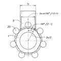
本発明では、玉数Zの玉軸受における(nZ±1)角のうねり振幅を修正するため、(Z−1)角をまたぐ軸受円周方向のまたぎ長さを持つ柱状砥石によって超仕上加工を行うことを特徴としている。ここでnは自然数である。玉軸受内外輪の(nZ±1)角は軸受半径方向の振動を大きくするうねり成分である。したがって(nZ±1)角のうねり振幅を小さくするのが本発明の目的であり、この角の頂点を円周方向にまたいで、最もうねり周期の大きな(Z−1)角以上の山を選択的に超仕上により修正する。図1は玉数が7個の場合について玉軸受内輪(ワーク)1と砥石3のまたぎ状態を模式的に示したものである。20は軸受内外輪間に介在される玉である。図中のTsがこの場合のまたぎ寸法であり、前述の式(2)で特定される。
【0022】
【発明の実施の形態】
次に、本発明を好適な実施形態について図面を参照して説明する。まず被加工物である玉軸受内輪の軌道面の超仕上加工について説明する。
内輪軌道面と砥石の接触状態について
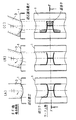
玉軸受内輪の軌道面を揺動する柱状砥石で超仕上加工する場合には、前記砥石は砥石全面が常に軌道面に接触しつつ加工することは不可能である。図2は砥石3とワークとなる内輪1の外周軌道面の接触状態を例示した図であり、砥石が揺動するに従って砥石3と前記ワークの接触状態が変化する様子を同図(A)から(C)まで段階的に表している。ここでは長方形断面の角柱砥石3の先端が同図(A)の直立状態から図中左方向に振れて、同図(B)の状態を経て、同図(C)の揺動振り角が最大状態となるまでを砥石揺動振り角0°(直立)時の砥石押圧方向から、つまりワーク上面から見た図と、これに該当するワーク円周方向の砥石中央位置(F−F線)における砥石断面図を示してある。なお、図2の「ワーク上面」を示す図では砥石は説明上図示省略してある。
【0023】
図2において、太線は揺動運動する砥石が通過しながらワーク1の軌道面に接触する「線当り」位置を示し、平行斜線で示された範囲は砥石揺動振り角が最大の瞬間においてのみ砥石が軌道面に広い面積で接触する「面当り」範囲を示している。ここで前記線当りとは、砥石の揺動軸中心から最も近いワーク表面を結んだ線を示し、前記面当りとは、砥石作用面上で軌道面と線当りしない部分に対して砥石揺動振り角最大時における軌道面形状が転写されて出来た砥石の形状が、再び振り角最大時に軌道面に接触する範囲を示す。
【0024】
砥石とワークの接触状態は、砥石が反対方向に揺動した場合の最大振り角位置では図2で軌道面底部の縦中央面(軸受軸線に垂直な軌道面底部中央面)に対し対称の形状となる。また途中の振り角位置では砥石位置に相応した範囲で線当りのみ生じる。
【0025】
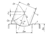
図3は図2における砥石揺動振り角最大時の砥石と内輪軌道面の接触状態を詳しく説明した図であり、図4は内輪軌道面に対する円弧中心Orと砥石揺動軸心Osとの関係を示した図である。図3は長方形断面の角柱砥石の先端が図中左方向に振れて、揺動振り角最大での接触状態を砥石揺動振り角0°(直立)時の砥石押圧方向から、つまり上面から見た図を示してある。なお、砥石は説明上図示省略してある。図2と同様に、図中で太線は揺動運動する砥石が通過しながら軌道面に接触する「線当り」位置を示し、平行斜線で示された範囲は砥石揺動振り角が最大の瞬間においてのみ砥石が軌道面に接触する「面当り」範囲を示している。なお、図中には玉軸受で転動体(玉)が軌道面と接触する位置(以下玉接触位置という)と軌道面底部及びワーク回転中心線Cが一点鎖線で記入してある。また、図上基礎となる点と座標軸X−Yを記入してある。Fが上述の玉接触位置であり、Gが軌道面底部である。
【0026】
接触状態図について
図3に示された砥石と内輪軌道面の接触状態は、砥石の面当り範囲が玉接触範囲を含み、円周方向またぎ長さが目的とする真円度多角うねりを覆う、本発明の効果を得るための理想的な状態である。
【0027】
内輪軌道面はその最大直径をDo、幅をBwとし、断面円弧半径をrwとする。また超仕上用砥石の断面形状(角柱砥石の長さ方向に直角な断面形状)は長方形で、またぎ寸法をTs、砥石幅(内輪軸方向に平行な幅)をBs(図3では図示省略)とする。図4に示すように、砥石揺動軸の軸心Osは内輪軌道面断面円弧中心Orからδsだけ軌道面方向にずれて位置し、最大砥石揺動振り角θsが与えられ、軌道面断面円弧半径rwより小さい揺動半径で内輪軸線を含む平面内(垂直平面内)で前記Osを中心に揺動させる。
図3を参照して、作図上、座標原点Oを内輪の縦横中心線の交点とし、内輪および砥石の幅方向をX、砥石のまたぎ方向をYとする。また図上基礎となる点をそれぞれp1、p2、p3、p4およびp5とし、p4またはp5を含む曲線を各々f4、f5とする。
【0028】
本発明の効果を得るためには、砥石またぎ方向の長さがTsなる面当り範囲が、軌道面上の玉接触位置を含むことが必要である。また同時に軌道面断面形状の悪化を起こさない様、各々の面当り範囲の大きさを調整する必要が有る。図中の面当り範囲α1、α2及びβを適切な大きさとするためには、砥石またぎ寸法Tsおよび面当り範囲α1、α2の境界線となるf4と、面当り範囲βの境界線、つまり曲線f5の位置と境界線を決定する点であるp1、p2の座標が重要である。
【0029】
点p1およびp2は線当り即ち砥石揺動軸中心から最も近い内輪軌道面上の点を結んだ線の節点であり、二つの点の間は直線で結んで差し支えない。p1およびp2のX座標は図より明らかであるが、Y座標は砥石揺動軸心と軌道面断面円弧中心の距離δsを変数とした関数であり、δsを大きくすることによりp1およびp2のY座標は大きくなる。即ち軌道面の幅方向中央でY方向に伸びる線当りを示す線分が長くなると共に、面当り範囲βはY方向に広がる。δsが0の場合は砥石揺動軸中心と軌道面断面円弧中心が一致してp1およびp2のY座標は0となり、面当り範囲βは消滅するが、p1とp2間およびp1とp5間の線当りは残る。δsが負の場合はこれらの線当りも消滅し、砥石と軌道面の当りは不安定になる。
【0030】
前記曲線f4は砥石揺動振り角最大時の砥石幅方向中央の母線位置であり、線当りを示す直線と共に、面当り範囲α1、α2の境界線となる。f4位置は最大砥石揺動振り角θsによる関数であり、θsが大きいとα1、α2は幅が小さくなる。
【0031】
曲線f5は砥石揺動振り角最大時における砥石作用面上の幅方向側面位置であり、線当りを示す図中の太い直線とともに、面当り範囲βの境界線となる。f5位置は最大砥石揺動振り角θsと砥石幅Bsによって決まる関数であり、θsが大きいほど、Bwが小さいほどf5は軌道面の縦中央線に近くなり、従ってβ範囲の幅は小さくなる。
以上により砥石と内輪軌道面の接触状態図を説明した。以下で本発明による最適接触状態を実現するための超仕上パラメータを説明する。
【0032】
内輪軌道面の超仕上パラメータについて
図3で長方形断面形状の柱状砥石のまたぎ寸法Tsは、内輪軌道面内最大円周上で目的とする真円度角数のうち最大の波長を有するもの、即ち[玉数−1]角のうねり波長に対する弦の長さを基に設定する。砥石またぎ寸法Tsは以下の式(2)で表す範囲が適正である。
【0033】
【数7】

【0034】
最大砥石揺動振り角θsは玉接触位置での軌道面断面円弧形状の精度を維持するため、玉と軌道面の接触角(以下玉接触角という)θc近傍とする。最大砥石揺動振り角θsは玉接触角θcの80%ないし200%の範囲が適正である。80%未満では、内輪軌道面の溝形状を軸受の接触角範囲にわたって充分な超仕上加工ができない。理論的には100%であれば良いが、超仕上前の内輪の軌道面溝形状の製作誤差、加工上の内輪取付誤差などを考えて砥石保持部材(砥石ホルダ)が干渉し加工に不具合を生じない範囲であれば、200%と余裕をもって設定するのが良い。
【0035】
玉軸受軌道面のうち特に玉接触位置近傍における真円度精度が重要である。本発明では砥石作用面の接触範囲内の平均化効果を利用して軸受内外輪表面を修正するのであるから、面当り接触範囲βが玉接触位置を含む必要がある。従って砥石幅は小さすぎると玉接触位置の真円度うねりが修正されず、大きすぎると砥石最大揺動振り角時に砥石が軌道面幅内に収まりきらず加工精度に悪影響を及ぼす。砥石幅Bsは内輪軌道面の幅Bwに対し80%ないし150%の範囲が適正である。本発明の最大砥石振り角θsの範囲では80%未満になると、砥石先端の振れ方向と反対側の当り面(β)のX方向の幅が小さくなり、内輪軌道面のうねりを修正することが困難となり、150%を超えると、この振れ方向反対側の内輪軌道面の溝からはみ出た部分の砥石が振動を起して加工精度を悪化させる。
【0036】
軌道面断面円弧形状の悪化を防ぐために、砥石揺動軸と軌道面断面円弧中心の距離δsを変更し、図3における軌道面幅中央部の線当りO−p1の長さ、即ち面当りβの円周方向範囲を調整する。δsが過大では軌道面断面円弧の中央部Gが過度に除去されて凹み、δsが過小では同円弧の中央部Gが除去されずに盛り上がって残る、または目的とする軌道面真円度のうねり角数が修正されない。後述の図15にも例示するように、例えば溝底での円周方向当り長さが長くなると、溝底が過度に除去されて溝形状がくずれる。しかがってδsは内輪軌道面の断面円弧半径rwに対し0ないし10%の範囲が適正である。
以上により本発明による最適接触状態を実現するための超仕上パラメータを説明した。
【0037】
次に、本発明の他の実施形態、即ち玉軸受外輪軌道面の超仕上加工の場合について説明する。
外輪軌道面と砥石の接触状態について
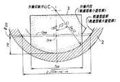
加工中の外輪軌道面と砥石の接触状態は図5に示されている。図5は長方形断面の角柱砥石が揺動振り角最大状態で外輪軌道面に接する状態を、砥石揺動振り角0°(直立)時の砥石押圧方向から見た平面図であり、ここでは図3と同様砥石は図示省略してある。なお外輪2は断面で示してある。図6は外輪軌道面に対する円弧中心と砥石3の揺動中心軸心との関係を示した図である。図5中、太線は揺動運動する砥石が通過しながら外輪軌道面に接触する「線当り」位置を示し、平行斜線で示された範囲は砥石揺動振り角が最大の瞬間に砥石が軌道面に接する「面当り」を示す。図5においては図3と同様に玉軸受で玉が外輪2の軌道面と接する位置、即ち玉接触位置Fと軌道面底部G及びワーク回転中心線Cが一点鎖線で示されている。
【0038】
接触状態図について
図5に示される砥石と軸受外輪軌道面の接触状態は、砥石の面当り接触範囲が玉接触位置を含み、円周方向接触長さが目的とする真円度多角うねりを覆う、本発明の効果を得るための理想的な状態である。また、長方形断面の砥石の作用面は最大揺動振り角時にすべて軌道面内に収まっている。超仕上パラメータを説明する前に、砥石と外輪軌道面の接触状態図を説明する。
【0039】
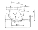
外輪軌道面はその最大直径をDe、幅をBweとし、断面円弧半径をreとする。また超仕上用砥石の断面形状は長方形で、またぎ寸法をTse、幅(外輪軸方向に平行な幅)をBseとする。図6に示すように、砥石揺動軸の軸心Oseは外輪軌道面断面円弧中心Oreからδseだけ外輪の回転軸心方向にずれて位置し、最大砥石揺動振り角θseが与えられ、軌道面断面円弧半径reより大きい揺動半径で外輪軸線を含む平面内(垂直平面内)で揺動させる。
図5を参照して、図上、座標原点Oを外輪の縦横中心線の交点とし、外輪及び砥石の幅方向をX、砥石のまたぎ方向をYとする。また作図上基礎となる点をp6、p7、p8、p9およびp10とし、p8を含む曲線をf8、p9及びp10を含む曲線をf9とする。
【0040】
本発明の効果を得るためには、砥石またぎ方向の長さがTseなる面当たり範囲が軌道面上の玉接触位置を含むことが必要である。また同時に軌道面断面形状の悪化を起こさない様、各々の面当り範囲の大きさを調整する必要がある。図中の面当り範囲γおよびε1、ε2を適切な大きさとするためには、外輪の場合の砥石またぎ寸法Tseと、面当り範囲γの境界線となる曲線f8と境界線を決定する点p6及びp7の座標と、面当り範囲ε1、ε2の境界線となる曲線f9の位置が重要である。
【0041】
p6およびp7は線当り即ち砥石揺動中心から最も近い外輪軌道面上の点を結んだ線の節点であり、二つの点の間は直線で結んで差し支えない。p6およびp7のX座標は図より明らかであるが、Y座標は砥石揺動軸心と軌道面断面円弧中心の距離δseを変数とした関数であり、δseを大きくすることによりp6及びp7のY座標は大きくなる。即ち面当り範囲γはY方向に広がる。δseが0の場合は砥石揺動軸中心と軌道面断面円弧中心が一致してp6およびp7のY座標は0となり、面当り範囲γは消滅するが、p6とp7間およびp6とp9間の線当りは残る。δseが負の場合はこれらの線当りも消滅し、砥石と軌道面の当りは不安定になる。
【0042】
曲線f8は砥石揺動振り角最大時の砥石幅方向中央の母線位置であり、線当りを示す直線と共に、面当り範囲γの境界線となる。f8位置は最大砥石揺動振り角θseによる関数であり、θseが大きいとf8位置は外輪軌道面端に近くなり、面当り範囲γは幅が小さくなる。
【0043】
曲線f9は砥石揺動振り角最大時の砥石作用面上の幅方向側面位置であり、線当りを示す直線とともに、面当り範囲ε1およびε2の境界線となる。f9位置は最大砥石揺動振り角θseと砥石幅Bseによって決まる関数であり、θseが大きいほど、Bseが小さいほど曲線f9は軌道面縦中央線に近くなり、面当り範囲ε1およびε2のX方向の幅は小さくなる。
以上により砥石と外輪軌道面の接触状態を説明したので、以下で本発明による最適接触状態を実現するための超仕上パラメータを説明する。
【0044】
外輪軌道面の超仕上パラメータについて
外輪軌道面に対する超仕上砥石またぎ寸法Tseは次式(3)の範囲が適正である。
【数8】
【数9 】
上述のまたぎ寸法Tseは小さい方が前記軌道面の断面円弧半径と砥石軌跡との違いが少なく望ましいが、またぎ寸法Tseが上記(3)式の下限を下回ると、うねりの頂点間距離より短くなり過ぎて本発明の目的であるうねり修正が困難となる。De・sin180°/(Z−1)=Tseがうねりの頂点を丁度またぐ寸法であって、うねりの片振幅の修正に対して理論的には好ましい値であるが、外輪軌道面溝加工の場合、外輪内径に挿入できる砥石の大きさの制限を受けるので、またぎ寸法を充分与えてうねりの修正機能を確保するため(3)式の上限とした。ただしTseの上限は砥石の揺動上、(4)式の制限を受けるので、この値を上限とした。
【0045】
最大砥石揺動振り角θseは、軸受外輪の内側に挿入し揺動運動させる砥石保持の為の治工具と外輪の干渉が生じない範囲で、玉接触角θcの近傍とする。最大砥石揺動振り角θseは玉接触角θcの50%ないし200%の範囲が適正である。この砥石揺動振り角θseは、軸受の外輪内径が小さくなると、この中に挿入される砥石保持部材も小さくせざるを得ず、揺動角もスペース上の制限を受け小さくせざるを得ず、内輪より小さな50%を下限とする。また、揺動振り角は可能な限り大きい方が外輪軌道面のうねり修正機能上からは望ましいので、上限は200%とする。
【0046】
図5の外輪軌道面に対して、砥石の面当り接触範囲ε1およびε2は玉接触位置を含む必要がある。砥石幅が小さすぎるとε1およびε2が玉接触位から外れると真円度うねりは修正されず、砥石幅が大きすぎると砥石最大振り角時に砥石が軌道面幅内に収まりきらず、砥石先端の振れ方向と反対側の外輪軌道面溝からはみ出た部分の砥石が欠け易く、軌道面を傷付けるおそれがあり、加工精度に悪影響を及ぼす。砥石幅Bseは外輪軌道面の幅Bweに対し80%ないし150%の範囲が適正である。
【0047】
軌道面断面円弧形状の悪化を防ぐため、即ち図5中の点p6座標と共に面当り範囲γの大きさを調整するために、砥石揺動軸心Oseと軌道面断面円弧中心Oreの距離δseを調整する。δseが過大では軌道面断面円弧の中央部が除去されずに盛り上がって残り、δseが過小では同円弧の中央部が過度に除去されて凹む、または軌道面全体に砥石が当たらずに前加工面が残る。δseは外輪軌道面の断面円弧半径reに対し0ないし10%の範囲が適正である。
【0048】
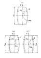
一方、砥石断面形状(砥石伸長方向に対して直角な横断面形状)を上述の長方形ではなく樽型として、砥石揺動振り角が最大時に砥石幅方向の側面を外輪軌道面の端と一致させる、即ち図5における曲線f9を軌道面端と一致させることにより、砥石と外輪軌道面の接触効率を向上させることが可能である。図8(a)の樽型砥石は砥石幅Bsyをまたぎ方向中央位置OneからのY方向変位を変数とする関数の式(5)を基に得られる本発明による最適な砥石形状である。
【数10】
また、砥石断面形状を図8(a)の砥石幅方向側面を構成する曲線を直線近似した多角形とすることにより砥石3の製造が容易となる。同図(b)あるいは(c)はその例である。いずれも砥石3の両側面はまたぎ方向中央線に対し対称に形成されている。
【0049】
次に、本発明を実施する場合の砥石ホルダ及びワーク保持構造を玉軸受内輪を例にとって説明する。
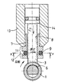
図9は本発明の実施例に係る玉軸受の内輪軌道面を超仕上加工する装置のワーク装着部分の側面断面図である。リング状のワーク1は玉軸受内輪であり、ワーク主軸装置10に装着されたバッキングプレート4の端部とプレッシャプレート5との間にワーク1が挟圧されて保持され、前記主軸装置10の駆動によりワーク1とバッキングプレート4およびプレッシャプレート5が一体で主軸軸線まわりに回転する。なおワーク1を軸線方向に固定する手段としては図示のプレッシャプレート5以外に例えばプレッシャロールなども採用され得る。ワーク1は径方向には該ワーク内に挿入されるシュー6によって支持され、シュー6上のワーク1の中心と主軸バッキングプレート4の中心の間に適当な大きさの偏心を持たせることにより、回転中のワーク1は常にシュー6に対して押し付けられた状態となっている。図9の実施例ではシュー6はワーク1の内径を支持する構成となっているが、ワーク1の外径部を支持する構造でも良く、またチャックなどでワーク1を主軸装置10の回転主軸に固定することもできる。
【0050】
後述する砥石ホルダ7は、ワーク軌道面断面円弧中心の近傍を軸心として主軸装置の主軸軸線を含む垂直平面内で適切に設定された振り角θsで揺動運動する。これと同時に砥石3は、図9には図示しない加圧ピストンによりワーク軌道面断面円弧の半径方向に押圧され(加圧力Fs)、これによってワーク軌道面は砥石3の先端作用面で超仕上加工される。なおワーク1はバッキングプレート4の端部位置まで図示しない供給装置により自動的に1個ずつ供給され、超仕上加工の終了したワークは自動的に排出されるとともに次ワークが自動的に供給され、このサイクルを繰り返す。
【0051】
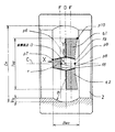
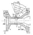
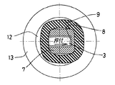
図10は本発明の実施例に係る砥石ホルダの縦断面図であり、ワーク1の内輪軌道面に対して砥石ホルダ7の先端に保持された砥石3が垂直に押し当てられている状態を示している。図10を参照すれば、砥石ホルダ7は内部に柱状砥石3を収容するように貫通する角穴が形成され、外側部の下部に大径フランジ部11を有し、このフランジ部11の外周に所定深さの切欠き12が形成されている。切欠き12はその片側部でホルダ角穴部と連通しており、このフランジ部外周の切欠き部位置にOリング9が或る程度の張力を有して装着されている。図11は図10のX−X面で切断した断面図である。図11を参照して、柱状砥石3は砥石ホルダ7の角穴内に或る隙間をもって挿入されるが、角穴部に通じる切欠き部位置で砥石3の片側部がOリング9に接当しかつ該Oリング9の張力により、柱状砥石3は砥石ホルダ7内の角穴部の反対側砥石案内面8に常に弾性的に押し付けられている。
【0052】
砥石またぎ寸法はワーク1の内輪軌道面真円度の注目する角数うねりの波長を覆うように設定されるため、柱状砥石3とワーク1は大きな円弧で接する。砥石3は回転するワーク1に引きずられてワーク円周方向に振動しやすく、砥石作用面形状がワーク1の軌道面の曲面と誤差を生じて摩耗する恐れがある。これを防止するために、図10に示す如く、砥石案内面8はワーク1の回転方向に対向する側に形成されており、これによって砥石3は砥石ホルダ7の角穴部砥石案内面8に対して常時弾性的に押し当てられた状態で使用される。砥石ホルダ7は大径フランジ部11より上部分がスリーブ13に嵌挿され、該スリーブ13内に設けられた加圧ピストン14により空圧付加手段などを介して砥石3がワーク1の軌道面に押し付けられる。
【0053】
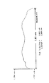
次に本発明による超仕上加工パラメータの設定例を示す。まず実施例の玉軸受は直径2mmの玉7個を接触角17°で有する構成としており、ワークとなる軸受内輪軌道面の最大直径は7.5mm、最小直径は7mm、幅は1.1mmである。軌道面断面円弧半径は玉半径と同じとする。
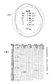
図12は従来の加工条件により超仕上加工された軸受内輪軌道面の玉接触部の真円度測定結果を示した図である。従来条件における砥石またぎ寸法は2.3mm(0.613De・sin180°/(Z−1)=0.613×3.75)である。同図(A)はうねり状態つまり内輪軌道面の玉接触部全周を拡大して示した図、同図(B)は真円度ハーモニクス解析を示している。図12(B)でUPRとあるのは1回転当りの山数(角数)であり、縦欄の0,5,10,15…はNの値を示している。真円度の測定はランクテーラーホブソン社のタリロンド73を使用した。図中の真円度ハーモニクス解析結果は真円度各角成分の片振幅をμm単位で表示してある。同図(B)中、横線で数値が記入されていない角数成分の片振幅は0.001μm、即ち1ナノメータ未満であることを示す。本例で目的とされる角数は玉数である7の自然数倍±1角、つまり(N±1)角、即ち6、8、13、15、……角であるが、各々4、3、1未満、1、……ナノメータの片振幅が測定されている。
【0054】
本発明による好適な内輪軌道面の超仕上加工パラメータ、即ち内輪軌道面に対する超仕上砥石の寸法、最大砥石揺動振り角および砥石揺動中心位置を決定する。なお本例では柱状超仕上砥石の断面形状を長方形としているが、これは別の任意断面形状であってもよい。砥石のまたぎ寸法Tsは、既に述べた式(2)により求められる。ここで式(2)中の係数を1.1とし、Doに7.5mm、Zに7を代入すると、Ts=4.1mmが得られる。また最大砥石揺動振り角θsは玉接触角θc=17(deg.)に対して120%を適用し、θs=20(deg.)とする。
【0055】
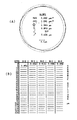
砥石幅を設定する際に本発明における適正範囲よりも小さすぎる値、即ち砥石幅Bsを内輪軌道面の幅Bw=1.1mmに対して70%としてBs=0.8mmを与え、既に設定したTs=4.1mmとθs=20(deg.)および後述のδs=0.05mmを用いて超仕上加工した内輪軌道面の玉接触部真円度測定結果を図13に示す。同図(B)のハーモニクス解析結果によれば、目的とする真円度角数うねり即ち6、8、13、15、……角は各々2、4、1未満、1未満、……ナノメータであり十分に修正されていない。
次に、砥石幅を本発明の適正範囲とした場合を説明する。砥石の幅方向側面が砥石振り角最大時にすべて軌道面内に収まる範囲で大きくした砥石幅、即ち内輪軌道面の幅に対して120%である砥石幅Bs=1.3mmを上述の条件に加えることによって得られた内輪軌道面の玉接触部真円度測定結果を図14に示す。図14(A)は内輪軌道面の玉接触部全周を拡大して示したである。同図(B)のハーモニクス解析結果によれば、目的とする真円度角数うねり即ち6、8、13、15、……角の片振幅は数秒の加工時間内にすべて1ナノメータ未満に修正されており、注目する[玉数−1]角以上のすべての角数うねりを選択的に極めて高精度に仕上げることができた。
【0056】
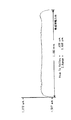
砥石揺動軸の軌道面断面円弧中からの軸心の距離δsを設定する際に本発明における適正範囲よりも大きすぎる値、即ちδsが内輪軌道面半径rw=1mmの15%つまりδs=0.15mmを既に設定したTs=4.1mm、θs=20(deg.)とBs=1.3mmと共に用いて超仕上加工した内輪軌道面の断面円弧形状を図15に示す。同図は軌道面断面円弧形状を単一円弧に近似した際の誤差を縦方向の凹凸で表し、図の横軸と平行な線より下方向へ凹んだ部分は目標よりも多く加工されたことを示す。また横軸方向は軌道面の幅方向を示し、ここでは軌道面の幅すべてが表示されている。図15によれば、内輪軌道面の幅方向中央部は目標よりも多く加工されて凹んでいる。
次に、砥石揺動軸の軌道面断面円弧中からの軸心の距離δsを本発明の適正範囲である、内輪軌道面半径rwに対し5%のδs=0.05mmとした場合の超仕上加工では、図16に示される内輪軌道面の断面円弧形状が測定された。図15と同様に横軸上に軌道面の全幅を表示してある。図16に示される軌道面断面円弧形状は単一円弧からの誤差が少なく良好である。また同時に測定された軌道面玉接触部の真円度測定結果は前記図14の通りであり、目的とする真円度角数のうねりは極めて高精度に仕上げられている。
【0057】
図17は本発明の他の実施例に係る超仕上加工装置によって軸受内輪軌道面の超仕上を行う状態を示した斜視図である。この実施例では図9〜図11のような柱状砥石を用いず、代りに先端が前記柱状砥石の先端円弧形状と同じ形状をなす柱状押圧治具15と、該押圧治具15の先端に密着される研磨テープ16が用いられる。研磨テープ16の片面、即ち研磨作用面には前述した砥石の砥粒サイズ、砥粒密度と同等な研磨材が付着されている。研磨テープ16は柱押圧治具15の両側に配置された支持ロール17に掛け渡されて押圧治具15の先端に一体的に張り付くように張力が与えられており、柱状押圧治具15を回転するワーク1に向けて押し付けながら、押圧治具15、研磨テープ16および支持ロール17が一体でワーク1の軌道面断面円弧中心の近傍の軸心位置15a(この軸心位置については図4、図6に関して既述した)を中心に揺動することにより、ワーク軌道面の超仕上加工がなされる。
【0058】
ワーク軌道面に対する柱状押圧治具15のまたぎ寸法、該治具先端の幅寸法、揺動振り角等は柱状砥石で既に述べた事項が適用される。研磨テープ16の作用面が磨耗した場合は該テープ16を長さ方向に所定量移動(インデックス)させることで押圧治具先端に新たな超仕上作用面を形成する。図示しないテープ供給部に巻かれた充分長い研磨テープを繰り出していくことにより、砥石の場合よりも取り付け、取り外しの交換頻度が少なく、その分加工能率が向上する。
【0059】
【発明の効果】
以上説明したように、本発明により求めた柱状超仕上砥石の断面寸法と、最大砥石揺動振り角および揺動軸と軌道面断面円弧中心の距離を適用することにより、玉軸受の内外輪軌道面で注目される真円度の玉数の自然数倍±1角のうねり成分を、軌道面断面円弧形状の崩れを起こさずに、極めて高精度に超仕上加工することができ、これによって上記玉軸受を組み込んだ主軸の非同期回転振れを低減することができる。
【図面の簡単な説明】
【図1】玉数が7個の場合について玉軸受内輪と砥石のまたぎ状態を模式的に示した図である。
【図2】砥石と内輪軌道面の接触状態の変化を例示した図である。
【図3】砥石揺動振り角最大状態で砥石と内輪軌道面の接触状態を例示した図である。
【図4】内輪軌道面に対する円弧中心Orと砥石の揺動軸心Osとの関係を示した図である。
【図5】砥石揺動振り角最大状態で長方形断面の砥石と外輪軌道面の接触状態を例示した図である。
【図6】外輪軌道面に対する円弧中心Oreと砥石の揺動軸心Oseとの関係を示した図である。
【図7】砥石と外輪軌道面の接触状態を外輪側面から見た断面図である。
【図8】外輪軌道面を超仕上する樽型あるいは樽型近似砥石の断面形状を示した図である。
【図9】本発明の実施例に係る玉軸受の内輪軌道面を超仕上加工する装置のワーク装着部分の側面断面図である。
【図10】本発明の実施例に係る砥石ホルダの縦断面図である。
【図11】本発明の実施例に係る砥石ホルダの横断面図である。
【図12】従来の超仕上加工方法による軸受内輪軌道面の玉接触位置の真円度測定結果を示す図である。
【図13】本発明を適用するが砥石幅が不適切な条件で超仕上加工した内輪軌道面の玉接触位置の真円度測定結果を示す図である。
【図14】本発明を適用して適切な条件により超仕上加工した軸受内輪軌道面の玉接触位置の真円度測定結果を示す図である。
【図15】本発明を適用するが砥石揺動軸心の位置が不適切な条件で超仕上加工した内輪軌道面の断面円弧形状の測定結果を示す図である。
【図16】本発明を適用して適切な砥石揺動軸心の位置で超仕上加工した内輪軌道面の断面円弧形状の測定結果を示す図である。
【図17】本発明の他の実施例に係る玉軸受の内輪軌道面を研磨テープにより超仕上加工する装置のワーク装着部分の斜視図である。
【符号の説明】
1 内輪
2 外輪
3 柱状砥石
4 バッキングプレート
5 プレッシャプレート
6 シュー
7 砥石ホルダ
8 砥石案内面
9 Oリング
10 ワーク主軸装置
11 フランジ
12 切欠き
13 スリーブ
14 加圧ピストン
15 柱状押圧治具
16 研磨テープ
17 支持ロール[0001]
[Field of the Invention]
The present invention relates to a super finishing method for correcting polygonal waviness of inner and outer ring raceway surfaces in a ball bearing for a hard disk drive (hereinafter referred to as HDD) main shaft motor of a magnetic recording device used in, for example, a personal computer. More specifically, the present invention relates to a superfinishing method for correcting the waviness of the roundness specific polygonal component of the ball bearing inner and outer ring raceway surfaces, which is one of the causes of asynchronous rotational runout, which is a problem in the HDD main shaft motor bearing, to be extremely small.
[0002]
Here, as already known, the undulation of the circularity specific polygonal component of the inner and outer ring raceways that causes the asynchronous rotational runout of the ball bearing, for example, the document “Eiichi Watabayashi, Rolling Bearing Manual, Japan As described in “Standards Association, page 169, 1999”, the undulations repeated on the circumference at a number corresponding to the natural number times ± 1 of the number of rolling elements (balls) interposed between the inner and outer ring raceway surfaces. Say.
[0003]
[Prior art]
While rocking a columnar grindstone with a rectangular or arbitrary cross-sectional shape, it is removed while pressing against the raceway surface of the inner ring or outer ring that is coaxial with the bearing rotation with an appropriate force in the radial direction of the cross-section arc of the raceway surface. A superfinishing method for the inner and outer ring raceways of the ball bearing that performs the above is already known. The rocking shaft of the grindstone is positioned at a right angle to the cutting direction of the grindstone and in the bearing axial direction at or near the center of the cross-section arc of the raceway surface to be processed, and the grindstone is rocked at an appropriate swinging angle. Oscillates repeatedly around the axis of movement.
[0004]
In a conventional ball bearing processing method, the bearing inner and outer ring raceways are ground and then finished by superfinishing. The grinding process is mainly responsible for accurately forming the cross-sectional arc shape of the raceway surface and the roundness in the rotational direction, and the superfinishing process has a polishing action that improves the surface roughness of the raceway surface after grinding. It is left to the Lord.
[0005]
However, even in this super-finishing process, irregularities with a period shorter than the length of the contact arc formed by projecting the “span” dimension of the grinding wheel on the workpiece processing surface circumference are corrected by the averaging effect within the contact range of the grinding wheel and the workpiece. It is a known fact. However, the rounded polygonal waviness corrected by this method is generally waviness of 10 to 20 or more, and for waviness components having a lower number of angles and a large period, the relative of the workpiece and the grindstone is exclusively used. Shape forming is performed by motion transfer processing based on transfer of motion accuracy.
[0006]
Based on the above-mentioned motion accuracy transfer processing theory, much effort has been put into improving the motion accuracy of the workpiece in the super finishing process. For example, US Pat. No. 5,679,061 describes that the rotational accuracy of a ring-shaped workpiece being processed is improved by supporting the rotating surface of the ring-shaped workpiece on a shoe with a hydrostatic oil film. ing. However, the efficiency of roundness correction is low in the super finishing method in which the cutting rigidity between the workpiece and the grindstone is small.
[0007]
In general, in the super finishing method in which a columnar grindstone is pressed against the outer peripheral surface of a rotating cylindrical workpiece and the grindstone is linearly reciprocated parallel to the workpiece rotation axis, the working surface of the grindstone is always machined entirely. Because it touches the surface of the workpiece, the waviness of the workpiece roundness can be easily corrected by using a super finishing whetstone that has a dimension that covers the waviness of one period even when the number of corners is less than 10 squares. Possible processing methods are known.
[0008]
[Problems to be solved by the invention]
However, in the case of the raceway surface of the inner ring or outer ring of the ball bearing, unlike the superfinishing of the outer peripheral surface of the cylindrical workpiece, the raceway surface on the working surface of the superfinishing grindstone that oscillates according to the geometrical positional relationship. The range of contact with the surface changes, and it is impossible to always bring the entire working surface into contact with the raceway surface. For this reason, it has been considered difficult to correct the waviness of roundness by increasing the straddling dimension of the grindstone to a wave having a low angle and a long wavelength.
[0009]
In relation to this problem, U.S. Pat. No. 3,423,887 related to the invention of SKF discloses a superfinishing grindstone having a straddle dimension equivalent to 1/3 of the circumferential length of the raceway surface of the ball bearing inner and outer rings. In order to improve the raceway surface waviness (polygonal waviness of roundness), the held grindstone is pressed against the raceway surface of the inner ring or the outer ring and is finely vertically at a high frequency of 5 to 30 kHz. A superfinishing method for maintaining the sharpness of a grindstone by vibrating is disclosed.
[0010]
However, in the super finishing method according to the above-mentioned invention of SKF, the cross-sectional arc shape of the raceway surface is obtained by transferring the shape of the grindstone itself by pressing the grindstone vertically against the raceway surface to be machined without swinging. It is a method that tries to maintain accuracy. Therefore, the distribution of the grinding amount varies on the working surface of the super-finishing grindstone due to the variation in the shape of the workpiece in the width direction and the cross-section arc shape error of the raceway surface that are successively supplied from the previous grinding step. Since the distribution of wear does not become uniform, the cross-sectional shape of the grindstone itself is easily broken, and it is difficult to ensure the accuracy of the cross-sectional arc shape of the raceway surface to which this is transferred.
[0011]
As is clear from the example of the invention of this SKF company, in order to accurately finish the cross-section arc shape of the raceway surface of the ball bearing inner and outer rings, the swinging motion of the superfinishing wheel is indispensable. A method of correcting the roundness polygonal undulation with high efficiency without causing the collapse of the arc shape has not yet been established.
[0012]
Accordingly, the present invention realizes a specific contact angle of the roundness of the raceway surface of the ball bearing inner and outer rings, that is, a grindstone contact length that covers the wave length of the [bearing ball number-1] angle, and [bearing ball number-1]. An object of the present invention is to provide a superfinishing method for correcting the amplitude of waviness of a corner and a shorter wavelength than that with high accuracy.
[0013]
[Means for Solving the Problems]
According to the present invention, while rotating the ball bearing raceway around the axis, the radial dimension of the cross section arc is 0 to 10% of the radial dimension in a direction perpendicular to the axis from the center of the cross section arc of the raceway surface of the raceway. The distance between the center of rotation of the raceway and the axis of rotation of the grinding wheel extending in the direction perpendicular to the axis of rotation of the raceway is centered on the axis of oscillation of the wheel. Range T,
[Expression 2]
![]()
However, in the above equation (1), Z is the number of balls of the bearing, D is the maximum diameter dimension in the raceway surface of the bearing race, and when the bearing race is an inner race, the wheel span dimension is Ts, the inner race Maximum diameter dimension in planeIsInner ring outer diameterTo the lawDo, or, in the case of the outer ring, Tse for the whetstone straddling dimension, the maximum diameter dimension in the outer ring raceway surfaceIsOuter ring groove diameterTo the lawDe is used in place of T and D, respectively.
[0014]
According to one aspect of the present invention, 0 to 10% of the radial dimension of the cross-section arc in a direction perpendicular to the axis from the center of the cross-section arc of the raceway surface of the inner ring while rotating the ball bearing inner ring about the axis. The distance between the center of rotation of the inner ring and the axis of rotation of the grindstone extending in the direction perpendicular to the rotation axis of the inner ring is the “stretching” dimension taken in the direction of the rocking axis. Ts in the range, that is, the maximum diameter in the inner ring raceway surfaceIsInner ring outer diameterThe lawDo, where Z is the number of balls in the bearing
[Equation 3]
![]()
[0015]
According to another aspect of the present invention, while rotating the ball bearing outer ring around the axis, the radial dimension of the cross-section arc is zero on the opposite side to the direction perpendicular to the axis from the center of the cross-section arc of the raceway surface of the outer ring. Further, the “spanning dimension” taken in the direction of the rocking axis about the grindstone rocking axis extending in the direction perpendicular to the rotation axis of the outer ring at a position away from the center of the arc of section by 10% is expressed by the following equation: Tse which is limited by the formula (4) within the range of (3), that is, the maximum diameter in the outer ring raceway surfaceIsOuter ring groove diameterThe lawDe, the number of bearing rolling elements (balls) is Z, the cross-sectional arc radius re of the outer ring raceway surface,
[Expression 4]
![]()
![]()
[0016]
According to another aspect of the present invention, in the above-described superfinishing method for a ball bearing outer ring raceway surface, the displacement y taken in the grinding wheel rocking axis direction is a variable, and the maximum diameter of the outer ring raceway surface is set.IsOuter ring groove diameterLaw De, the outer ring raceway surface cross-sectional arc radius re, the outer ring raceway depth Po, the outer ring raceway surface width Bwe, and the maximum grinding wheel rocking swing angle θse, and the width dimension of the columnar grinding wheel taken in the bearing outer ring rotation axis direction. Superfinishing of the ball bearing outer ring raceway surface based on the following equation (5) with Bsy as a function, and the cross-sectional shape of the grinding wheel is a barrel shape that is axisymmetric with respect to the center line, or a polygon that approximates the barrel shape linearly. A processing method is provided.
[Formula 6]
![]()
[0017]
Further, according to the present invention, in the grindstone holder that holds the columnar grindstone having the spanning dimension Ts or Tse and is used for super finishing of the ball bearing inner and outer ring raceway surfaces, the columnar grindstone becomes the ball bearing inner ring or outer ring. There is provided a grindstone holder having a grindstone guide surface formed so as to oppose the rotation direction of the workpiece, and means for pressing the columnar grindstone against the grindstone guide surface via an elastic body.
[0018]
According to another aspect of the present invention, in the superfinishing method for the ball bearing inner ring raceway surface, instead of the columnar grindstone having a straddle dimension Ts, a columnar press having a tip shape equivalent to the columnar grindstone. Using a jig and a polishing tape sandwiched between and extending between the ball bearing inner ring raceway surface and the columnar pressing jig, the columnar pressing jig is moved while rotating the ball bearing inner ring about an axis. While pressing the inner ring raceway surface of the inner ring raceway surface in a radial direction through a polishing tape, the columnar pressing jig is placed around the same axis as the swing center axis of the columnar grindstone in the super finishing method of the ball bearing inner ring raceway surface. There is provided a superfinishing method for a raceway surface of a ball bearing inner ring using an abrasive tape characterized by swinging integrally with the abrasive tape.
[0019]
According to another aspect of the present invention, in the above-described superfinishing method for the ball bearing outer ring raceway surface, instead of the columnar grindstone having a straddle dimension Tse, a columnar press having a tip shape equivalent to the columnar grindstone Using a jig and a polishing tape that is sandwiched between and extends between the ball bearing outer ring raceway surface and the columnar pressing jig, the columnar pressing jig is moved while rotating the ball bearing outer ring about an axis. While pressing the outer ring raceway surface of the outer ring raceway surface in a radial direction through a polishing tape, the columnar pressing jig is placed around the same axis as the swing center axis of the columnar grindstone in the super finishing method of the ball bearing outer ring raceway surface. A superfinishing method for a ball bearing outer ring raceway surface using a polishing tape is provided, wherein the polishing tape is rocked integrally with the polishing tape.
[0020]
According to the present invention, in the ball bearing in which a plurality of rolling elements (balls) are interposed between the inner ring and the outer ring, at least one of the inner ring and the outer ring has a [number of bearing balls −1] angle and swells therefrom. A ball bearing is provided in which the amplitude of all the waviness of the raceway surface with a short period is less than 1 nm (nanometer) in half amplitude.
[0021]
[Action]
In the present invention, in order to correct the waviness amplitude of the (nZ ± 1) angle in the ball bearing having the number of balls Z, super finishing is performed by a columnar grindstone having a straddling length in the bearing circumferential direction across the (Z-1) angle. It is characterized by doing. Here, n is a natural number. The (nZ ± 1) angle of the inner and outer rings of the ball bearing is a swell component that increases vibration in the bearing radial direction. Therefore, it is an object of the present invention to reduce the undulation amplitude of the (nZ ± 1) angle, and select a mountain having the largest undulation period and the (Z-1) angle or more across the apex of the angle in the circumferential direction. To correct by super finishing. FIG. 1 schematically shows the straddle state between the ball bearing inner ring (workpiece) 1 and the
[0022]
DETAILED DESCRIPTION OF THE INVENTION
Next, preferred embodiments of the present invention will be described with reference to the drawings. First, superfinishing of the raceway surface of the ball bearing inner ring, which is a workpiece, will be described.
Contact state between inner ring raceway surface and grinding wheel
When superfinishing is performed with a columnar grindstone that swings the raceway surface of the ball bearing inner ring, the grindstone cannot be machined while the entire grindstone is always in contact with the raceway surface. FIG. 2 is a diagram illustrating the contact state between the
[0023]
In FIG. 2, the thick line indicates the “per line” position where the rocking wheel that is rocking moves and contacts the raceway surface of the
[0024]
The contact state between the grindstone and the workpiece is symmetric with respect to the vertical center plane of the raceway bottom (the raceway bottom center plane perpendicular to the bearing axis) in FIG. 2 at the maximum swing angle when the grindstone swings in the opposite direction. It becomes. In addition, at the swing angle position in the middle, it occurs only per line in a range corresponding to the position of the grindstone.
[0025]
FIG. 3 is a diagram for explaining in detail the contact state between the grindstone and the inner ring raceway surface in FIG. 2 when the grinding wheel swing swing angle is maximum, and FIG. 4 shows the relationship between the arc center Or and the grindstone swing axis Os with respect to the inner ring raceway surface. FIG. FIG. 3 shows that the tip of the rectangular column grindstone having a rectangular cross section is swung to the left in the figure, and the contact state at the maximum rocking swing angle is viewed from the grinding wheel pressing direction when the rocking rocking swing angle is 0 ° (upright), that is, from the top. The figure is shown. Note that the grindstone is not shown for the sake of explanation. As in FIG. 2, the thick line in the figure indicates the “per line” position where the rocking rocking wheel passes and contacts the raceway surface, and the range indicated by the parallel diagonal lines is the moment when the rocking rocking swing angle is maximum. The “per surface” range in which the grindstone contacts the raceway surface is shown only in FIG. In the drawing, a position where the rolling element (ball) contacts the raceway surface (hereinafter referred to as a ball contact position), a bottom portion of the raceway surface, and a workpiece rotation center line C are indicated by a one-dot chain line. In addition, the basic points and the coordinate axes XY are entered in the figure. F is the ball contact position described above, and G is the bottom of the raceway surface.
[0026]
About the contact state diagram
The contact state between the grindstone and the inner ring raceway surface shown in FIG. 3 is that the surface contact range of the grindstone includes the ball contact range, and the circumferential span span covers the desired roundness polygonal waviness. It is an ideal state for obtaining.
[0027]
The inner ring raceway surface has a maximum diameter Do, a width Bw, and a cross-sectional arc radius rw. Further, the cross-sectional shape of the super finishing grindstone (cross-sectional shape perpendicular to the length direction of the prismatic grindstone) is a rectangle, the straddle dimension is Ts, and the grindstone width (width parallel to the inner ring axial direction) is Bs (not shown in FIG. 3). And As shown in FIG. 4, the axis Os of the grindstone rocking shaft is positioned to be shifted in the track surface direction by δs from the inner ring raceway cross-section arc center Or, and is given a maximum grindstone rocking swing angle θs. Oscillation is performed around the Os in a plane (in the vertical plane) including the inner ring axis with an oscillation radius smaller than the radius rw.
Referring to FIG. 3, on the drawing, the coordinate origin O is the intersection of the vertical and horizontal center lines of the inner ring, the width direction of the inner ring and the grindstone is X, and the straddling direction of the grindstone is Y. In addition, the basic points in the figure are p1, p2, p3, p4 and p5, respectively, and the curves including p4 or p5 are f4 and f5, respectively.
[0028]
In order to obtain the effect of the present invention, it is necessary that the per-surface range in which the length in the grinding wheel spanning direction is Ts includes the ball contact position on the raceway surface. At the same time, it is necessary to adjust the size of the per-surface range so that the cross-sectional shape of the raceway surface does not deteriorate. In order to appropriately set the per-surface ranges α1, α2, and β in the figure, f4 which is a boundary line between the grinding wheel spanning dimension Ts and the per-surface ranges α1, α2 and the boundary line of the per-surface range β, that is, a curve The coordinates of p1 and p2, which are the points that determine the position and boundary line of f5, are important.
[0029]
Points p1 and p2 are nodes of a line connecting the points on the inner ring raceway surface closest to the center, that is, the center of the grindstone rocking axis, and the two points may be connected by a straight line. The X coordinate of p1 and p2 is clear from the figure, but the Y coordinate is a function with the distance δs between the grinding wheel rocking axis and the center of the raceway surface cross section as a variable. By increasing δs, the Y coordinate of p1 and p2 Coordinates become larger. That is, the line segment indicating the line contact extending in the Y direction at the center in the width direction of the raceway surface becomes longer, and the surface contact range β extends in the Y direction. When δs is 0, the center of the rocking wheel rocking axis coincides with the center of the raceway cross-section arc, the Y coordinate of p1 and p2 becomes 0, and the surface contact range β disappears, but between p1 and p2 and between p1 and p5 Per line remains. When δs is negative, the contact between these lines disappears, and the contact between the grindstone and the raceway surface becomes unstable.
[0030]
The curve f4 is the position of the generatrix in the center of the grindstone width direction when the grindstone swing angle is maximum, and is a boundary line between the surface contact ranges α1 and α2 along with a straight line indicating line contact. The f4 position is a function of the maximum wobble rocking swing angle θs, and when θs is large, the widths of α1 and α2 are small.
[0031]
A curve f5 is a position in the width direction on the grindstone working surface when the grindstone swing angle is maximum, and becomes a boundary line of the surface contact range β along with a thick straight line in the drawing showing the line contact. The f5 position is a function determined by the maximum grindstone rocking swing angle θs and the grindstone width Bs. As θs is larger and Bw is smaller, f5 is closer to the longitudinal center line of the raceway surface, and therefore the width of the β range is smaller.
The contact state diagram of the grindstone and the inner ring raceway surface has been described above. The superfinishing parameters for realizing the optimum contact state according to the present invention will be described below.
[0032]
Super finishing parameters of inner ring raceway surface
In FIG. 3, the straddling dimension Ts of the columnar grindstone having a rectangular cross-sectional shape has the maximum wavelength among the target roundness angles on the maximum circumference in the inner ring raceway surface, that is, [number of balls-1] corners. Set based on the length of the chord relative to the waviness wavelength. The range represented by the following formula (2) is appropriate for the grinding wheel spanning dimension Ts.
[0033]
[Expression 7]
[0034]
The maximum grindstone rocking swing angle θs is set in the vicinity of the contact angle between the balls and the raceway surface (hereinafter referred to as the ball contact angle) θc in order to maintain the accuracy of the raceway surface cross-section arc shape at the ball contact position. The maximum wobble rocking swing angle θs is appropriately in the range of 80% to 200% of the ball contact angle θc. If it is less than 80%, sufficient superfinishing of the groove shape of the inner ring raceway surface over the contact angle range of the bearing cannot be performed. Theoretically, it may be 100%, but considering the manufacturing error of the raceway groove shape of the inner ring before super finishing, the inner ring mounting error in processing, etc., the grinding wheel holding member (grinding wheel holder) interferes and troubles in machining. If it does not occur, it should be set with a margin of 200%.
[0035]
Of the ball bearing raceways, roundness accuracy is particularly important near the ball contact position. In the present invention, since the surface of the inner and outer rings of the bearing is corrected by utilizing the averaging effect within the contact range of the grindstone working surface, the contact range β per surface needs to include the ball contact position. Therefore, if the grindstone width is too small, the roundness undulation at the ball contact position is not corrected, and if it is too large, the grindstone does not fit within the raceway width at the maximum rocking swing angle, which adversely affects machining accuracy. The grinding wheel width Bs is appropriately in the range of 80% to 150% with respect to the width Bw of the inner ring raceway surface. When the maximum whetstone swing angle θs of the present invention is less than 80%, the width in the X direction of the contact surface (β) on the opposite side to the wobbling direction of the grindstone tip becomes small, and the waviness of the inner raceway surface can be corrected. When it exceeds 150%, the grindstone protruding from the groove on the inner ring raceway surface on the opposite side of the runout direction vibrates and deteriorates the machining accuracy.
[0036]
In order to prevent the raceway cross-section arc shape from deteriorating, the distance δs between the grindstone rocking shaft and the raceway cross-section arc center is changed, and the length O-p1 per line at the center of the raceway width in FIG. Adjust the circumferential range of. When δs is excessively large, the central portion G of the circular arc of the raceway surface section is excessively removed and recessed, and when δs is excessively small, the central portion G of the circular arc is not removed and remains swelled, or the swell of the desired circularity of the raceway surface is obtained. The number of corners is not corrected. As illustrated in FIG. 15 to be described later, for example, when the length per circumferential direction at the groove bottom is increased, the groove bottom is excessively removed and the groove shape is broken. Accordingly, the range of 0 to 10% is appropriate for δs with respect to the cross-sectional arc radius rw of the inner ring raceway surface.
The superfinishing parameters for realizing the optimum contact state according to the present invention have been described above.
[0037]
Next, another embodiment of the present invention, that is, a case of superfinishing the ball bearing outer ring raceway surface will be described.
Contact state between outer ring raceway surface and grinding wheel
FIG. 5 shows the contact state between the outer ring raceway surface and the grindstone during processing. FIG. 5 is a plan view of the state in which the rectangular column grindstone having a rectangular cross section is in contact with the outer ring raceway surface in the maximum swing angle, as viewed from the grinding wheel pressing direction when the swing angle is 0 ° (upright). As with 3, the grindstone is not shown. The
[0038]
About the contact state diagram
The contact state between the grindstone and the bearing outer ring raceway surface shown in FIG. 5 is that the contact area per surface of the grindstone includes the ball contact position, and the circumferential contact length covers the desired roundness polygonal swell. This is an ideal state for obtaining an effect. In addition, the working surface of the grindstone having a rectangular cross section is all within the raceway surface at the maximum swing angle. Before explaining the super finishing parameters, the contact state diagram of the grindstone and the outer ring raceway surface will be explained.
[0039]
The outer ring raceway surface has a maximum diameter De, a width Bwe, and a cross-sectional arc radius re. The cross-sectional shape of the superfinishing grindstone is a rectangle, the span dimension is Tse, and the width (width parallel to the outer ring axial direction) is Bse. As shown in FIG. 6, the axis Ose of the grindstone rocking shaft is positioned to be shifted in the direction of the rotation axis of the outer ring by δse from the arc center Ore of the outer ring raceway surface, and given the maximum grindstone rocking swing angle θse. Oscillation is performed within a plane (in the vertical plane) including the outer ring axis with an oscillation radius larger than the circular arc radius re.
With reference to FIG. 5, in the figure, the coordinate origin O is the intersection of the vertical and horizontal center lines of the outer ring, the width direction of the outer ring and the grindstone is X, and the straddling direction of the grindstone is Y. Further, points that are the basis for drawing are p6, p7, p8, p9, and p10, and a curve that includes p8 is f8, and a curve that includes p9 and p10 is f9.
[0040]
In order to obtain the effect of the present invention, it is necessary that the surface contact range in which the length in the grinding wheel spanning direction is Tse includes the ball contact position on the raceway surface. At the same time, it is necessary to adjust the size of the per-surface range so that the cross-sectional shape of the raceway surface does not deteriorate. In order to make the per-surface ranges γ and ε1, ε2 in the figure appropriate sizes, the grinding wheel spanning dimension Tse in the case of the outer ring, the curve f8 that becomes the boundary line of the per-surface range γ, and the point p6 that determines the boundary line And the coordinates of p7 and the position of the curve f9 that is the boundary line between the per-surface ranges ε1 and ε2 are important.
[0041]
p6 and p7 are the nodes of the line connecting the points on the outer ring raceway surface which are closest to the line, that is, from the center of rocking of the grindstone, and the two points may be connected by a straight line. The X coordinate of p6 and p7 is clear from the figure, but the Y coordinate is a function with the distance δse between the grinding wheel rocking axis and the center of the raceway surface arc as a variable. By increasing δse, the Y coordinate of p6 and p7 Coordinates become larger. That is, the surface contact range γ extends in the Y direction. When δse is 0, the center of the grindstone rocking axis coincides with the center of the raceway cross-section arc, the Y coordinate of p6 and p7 is 0, and the surface contact range γ disappears, but between p6 and p7 and between p6 and p9 Per line remains. When δse is negative, the contact between these lines disappears, and the contact between the grindstone and the raceway surface becomes unstable.
[0042]
A curve f8 is a center line position of the wheel width direction center at the time when the rocking rocking swing angle is maximum, and becomes a boundary line of the surface contact range γ together with a straight line indicating the line contact. The f8 position is a function of the maximum wobbling rocking swing angle θse. When θse is large, the f8 position is close to the outer ring raceway surface end, and the surface contact range γ becomes small.
[0043]
A curve f9 is a position in the width direction on the grindstone working surface when the grindstone swing angle is maximum, and becomes a boundary line between the surface contact ranges ε1 and ε2 together with a straight line indicating the line contact. The f9 position is a function determined by the maximum grindstone swing angle θse and the grindstone width Bse. The larger the θse and the smaller the Bse, the closer the curve f9 is to the longitudinal center line of the raceway surface, and the X direction of the per-surface ranges ε1 and ε2 The width of becomes smaller.
Since the contact state between the grindstone and the outer ring raceway surface has been described above, super finishing parameters for realizing the optimum contact state according to the present invention will be described below.
[0044]
Super finishing parameters of outer ring raceway surface
The range of the following formula (3) is appropriate for the superfinishing wheel spanning dimension Tse for the outer ring raceway surface.
[Equation 8]
[Equation 9]
The smaller the above-mentioned straddling dimension Tse is preferable because the difference between the cross-sectional arc radius of the raceway surface and the grindstone trajectory is small, but if the straddling dimension Tse is below the lower limit of the above equation (3), it becomes shorter than the distance between the vertices of waviness. Thus, the swell correction that is the object of the present invention becomes difficult. De · sin 180 ° / (Z−1) = Tse is a dimension that just straddles the top of the undulation and is a theoretically preferable value for correction of the undulation half amplitude. Since the size of the grindstone that can be inserted into the inner diameter of the outer ring is limited, the upper limit of the expression (3) is set in order to secure a function for correcting waviness by giving sufficient straddle dimensions. However, since the upper limit of Tse is restricted by the equation (4) due to the rocking of the grindstone, this value is set as the upper limit.
[0045]
The maximum grindstone rocking swing angle θse is set in the vicinity of the ball contact angle θc within a range in which no interference occurs between the jig for holding the grindstone inserted into the bearing outer ring and swinging and the outer ring. The maximum wobble rocking swing angle θse is appropriately in the range of 50% to 200% of the ball contact angle θc. When the inner diameter of the outer ring of the bearing is reduced, the grindstone swinging angle θse must be reduced because the grindstone holding member inserted therein is also reduced due to space limitations. The lower limit is 50% smaller than the inner ring. Further, since it is desirable that the swing swing angle is as large as possible from the viewpoint of the function of correcting the waviness of the outer ring raceway surface, the upper limit is set to 200%.
[0046]
With respect to the outer ring raceway surface of FIG. 5, the contact ranges ε1 and ε2 of the grindstone need to include the ball contact positions. If the wheel width is too small, the roundness undulation will not be corrected if ε1 and ε2 deviate from the ball contact position. If the wheel width is too large, the wheel will not fit within the raceway width at the maximum swing angle of the wheel, and the wobble at the tip of the wheel The grindstone protruding from the outer raceway groove on the opposite side to the direction is likely to be chipped, which may damage the raceway, which adversely affects machining accuracy. The grinding wheel width Bse is suitably in the range of 80% to 150% with respect to the width Bwe of the outer ring raceway surface.
[0047]
In order to prevent deterioration of the raceway surface arc shape, that is, to adjust the size of the surface contact range γ together with the point p6 coordinate in FIG. 5, the distance δse between the grinding wheel rocking axis Ose and the raceway surface arc center Ore is set. adjust. If δse is excessive, the central part of the arc of the raceway surface cross section is not removed, but remains swelled, and if δse is excessively small, the central part of the arc is excessively removed and recessed, or the pre-machined surface does not hit the entire raceway surface. Remains. The range of 0 to 10% is appropriate for δse with respect to the cross-sectional arc radius re of the outer ring raceway surface.
[0048]
On the other hand, the cross-sectional shape of the grindstone (cross-sectional shape perpendicular to the grindstone extension direction) is a barrel shape instead of the above-mentioned rectangle, and the side surface in the grindstone width direction coincides with the end of the outer ring raceway surface when the grindstone swing angle is maximum. That is, by making the curve f9 in FIG. 5 coincide with the end of the raceway surface, it is possible to improve the contact efficiency between the grindstone and the outer raceway surface. The barrel-shaped grindstone in FIG. 8A has an optimum grindstone shape according to the present invention obtained based on the function formula (5) with the displacement in the Y direction from the central position One in the stride direction across the grindstone width Bsy.
[Expression 10]
Moreover, the
[0049]
Next, the grindstone holder and the work holding structure when the present invention is implemented will be described by taking a ball bearing inner ring as an example.
FIG. 9 is a side cross-sectional view of a work mounting portion of an apparatus for superfinishing an inner ring raceway surface of a ball bearing according to an embodiment of the present invention. The ring-shaped
[0050]
The
[0051]
FIG. 10 is a longitudinal sectional view of a grindstone holder according to an embodiment of the present invention, showing a state in which the
[0052]
Since the whetstone straddling dimension is set so as to cover the wavelength of the waviness of the angular swell of interest of the roundness of the inner ring raceway surface of the
[0053]
Next, an example of setting super finishing parameters according to the present invention will be shown. First, the ball bearing of the example has a configuration in which seven balls having a diameter of 2 mm are provided at a contact angle of 17 °. The maximum diameter of the bearing inner ring raceway surface as a workpiece is 7.5 mm, the minimum diameter is 7 mm, and the width is 1.1 mm. is there. The arc radius of the raceway section is the same as the ball radius.
FIG. 12 is a diagram showing the roundness measurement result of the ball contact portion of the bearing inner ring raceway surface that has been superfinished according to conventional machining conditions. The grindstone spanning dimension under the conventional conditions is 2.3 mm (0.613 De · sin 180 ° / (Z−1) = 0.613 × 3.75). FIG. 6A is an enlarged view showing the swell state, that is, the entire circumference of the ball contact portion of the inner ring raceway surface, and FIG. 5B shows the roundness harmonics analysis. In FIG. 12B, UPR indicates the number of peaks (number of corners) per rotation, and 0, 5, 10, 15... In the column indicate N values. Roundness was measured using a Tailrond 73 from Rank Taylor Hobson. The roundness harmonics analysis result in the figure shows the half amplitude of each angular component of roundness in μm units. In FIG. 5B, the half amplitude of the angular component whose numerical value is not entered with a horizontal line indicates 0.001 μm, that is, less than 1 nanometer. The target number of angles in this example is a natural number multiple of 7 which is the number of balls ± 1 angle, that is, (N ± 1) angle, that is, 6, 8, 13, 15,... 3, Less than 1, 1, ... Nanometer half amplitude is measured.
[0054]
The preferred superfinishing parameters of the inner ring raceway surface according to the present invention, that is, the dimensions of the superfinishing wheel with respect to the inner ring raceway surface, the maximum wobble rocking swing angle, and the whetstone rocking center position are determined. In addition, in this example, although the cross-sectional shape of the columnar superfinishing grindstone is a rectangle, this may be another arbitrary cross-sectional shape. The straddle dimension Ts of the grindstone is obtained by the above-described equation (2). Here, when the coefficient in the equation (2) is 1.1, 7.5 mm is substituted for Do, and 7 is substituted for Z, Ts = 4.1 mm is obtained. The maximum wobble rocking swing angle θs is 120% with respect to the ball contact angle θc = 17 (deg.), And θs = 20 (deg.).
[0055]
When setting the grindstone width, a value that is too small than the appropriate range in the present invention, that is, the grindstone width Bs is set to 70% with respect to the inner ring raceway surface width Bw = 1.1 mm, and Bs = 0.8 mm is given. FIG. 13 shows the ball contact portion roundness measurement result of the inner ring raceway surface superfinished using Ts = 4.1 mm, θs = 20 (deg.), And δs = 0.05 mm described later. According to the result of the harmonics analysis in FIG. (B), the desired roundness angle undulation, ie, 6, 8, 13, 15,..., The angle is 2, 4, less than 1, less than 1, each is nanometer. There is not enough correction.
Next, the case where the grindstone width is within the proper range of the present invention will be described. The wheel width Bs = 1.3 mm, which is 120% with respect to the width of the inner ring raceway surface, is added to the above-described conditions, so that the width of the side surface in the width direction of the grindstone is large enough to be within the raceway surface when the grinding wheel swing angle is maximum. The ball contact part roundness measurement result of the inner ring raceway surface obtained by this is shown in FIG. FIG. 14A is an enlarged view of the entire circumference of the ball contact portion of the inner ring raceway surface. According to the harmonics analysis result in Fig. 5B, the target roundness angle swell, ie, 6, 8, 13, 15, ..., the angular amplitude of each corner was corrected to less than 1 nanometer within a processing time of a few seconds. Therefore, it was possible to selectively finish all the undulations of the number of corners larger than the [number of balls-1] corners of interest.
[0056]
When setting the distance δs of the shaft center from the raceway cross-section arc of the grindstone rocking shaft, a value that is too larger than the appropriate range in the present invention, that is, δs is 15% of the inner ring raceway surface radius rw = 1 mm, that is, δs = 0. FIG. 15 shows a cross-sectional arc shape of the inner ring raceway surface that has been superfinished using Ts = 4.1 mm, θs = 20 (deg.) And Bs = 1.3 mm, in which .15 mm has already been set. The figure shows the error when approximating the circular arc shape of the cross section of the raceway surface to a single arc, with vertical irregularities, and the part recessed downward from the line parallel to the horizontal axis in the figure was processed more than the target Indicates. The horizontal axis direction indicates the width direction of the raceway surface. Here, the entire width of the raceway surface is displayed. According to FIG. 15, the center part in the width direction of the inner ring raceway surface is processed and recessed more than the target.
Next, superfinishing is performed when the distance δs of the axis from the cross-section arc of the raceway surface of the grindstone rocking shaft is 5% of the inner ring raceway surface radius rw, which is an appropriate range of the present invention, and δs = 0.05 mm. In machining, the cross-sectional arc shape of the inner ring raceway surface shown in FIG. 16 was measured. Similar to FIG. 15, the full width of the track surface is displayed on the horizontal axis. The raceway cross-section arc shape shown in FIG. 16 is favorable with few errors from a single arc. Further, the roundness measurement result of the contact surface ball contact portion measured at the same time is as shown in FIG. 14, and the undulation of the target roundness angle number is finished with extremely high accuracy.
[0057]
FIG. 17 is a perspective view showing a state in which the bearing inner ring raceway surface is superfinished by the superfinishing apparatus according to another embodiment of the present invention. In this embodiment, the columnar grindstone as shown in FIGS. 9 to 11 is not used, and instead, the
[0058]
For the straddle dimension of the
[0059]
【The invention's effect】
As described above, the inner and outer ring raceways of the ball bearing are obtained by applying the cross-sectional dimension of the columnar superfinishing grindstone obtained according to the present invention, the maximum wobblestone swing angle and the distance between the swing shaft and the raceway cross-section arc center. It is possible to superfinish the waviness component of natural number times ± 1 corner of the number of balls of roundness that is noticed on the surface with extremely high accuracy without causing the arc shape of the raceway surface to collapse. Asynchronous rotational runout of a spindle incorporating a ball bearing can be reduced.
[Brief description of the drawings]
FIG. 1 is a diagram schematically showing the straddle state between a ball bearing inner ring and a grindstone when the number of balls is seven.
FIG. 2 is a diagram illustrating a change in a contact state between a grindstone and an inner ring raceway surface.
FIG. 3 is a diagram exemplifying a contact state between a grindstone and an inner ring raceway surface in a state in which the grindstone swing angle is maximum.
FIG. 4 is a view showing a relationship between an arc center Or with respect to an inner ring raceway surface and a rocking axis Os of a grindstone.
FIG. 5 is a diagram exemplifying a contact state between a grindstone having a rectangular cross section and an outer ring raceway surface in a state in which the grindstone swing angle is maximum.
FIG. 6 is a diagram showing the relationship between the arc center Ore and the rocking axis Ose of the grindstone with respect to the outer ring raceway surface.
FIG. 7 is a cross-sectional view of a contact state between a grindstone and an outer ring raceway surface as viewed from the side of the outer ring.
FIG. 8 is a diagram showing a cross-sectional shape of a barrel-type or barrel-type approximate grindstone that superfinishes the outer ring raceway surface.
FIG. 9 is a side cross-sectional view of a work mounting portion of an apparatus for superfinishing an inner ring raceway surface of a ball bearing according to an embodiment of the present invention.
FIG. 10 is a longitudinal sectional view of a grindstone holder according to an embodiment of the present invention.
FIG. 11 is a cross-sectional view of a grindstone holder according to an embodiment of the present invention.
FIG. 12 is a view showing a roundness measurement result of a ball contact position on a bearing inner ring raceway surface by a conventional super finishing method.
FIG. 13 is a diagram showing a roundness measurement result of a ball contact position on an inner ring raceway surface to which the present invention is applied but superfinished under conditions where the grindstone width is inappropriate.
FIG. 14 is a diagram showing a roundness measurement result of a ball contact position on a bearing inner ring raceway surface superfinished under appropriate conditions by applying the present invention.
FIG. 15 is a diagram showing a measurement result of a cross-sectional arc shape of an inner ring raceway surface to which the present invention is applied but superfinished under conditions where the position of the grinding wheel rocking axis is inappropriate.
FIG. 16 is a diagram showing a measurement result of a cross-sectional arc shape of an inner ring raceway surface which is superfinished at an appropriate position of a grinding wheel rocking axis applying the present invention.
FIG. 17 is a perspective view of a work mounting portion of an apparatus for superfinishing an inner ring raceway surface of a ball bearing according to another embodiment of the present invention with an abrasive tape.
[Explanation of symbols]
1 Inner ring
2 Outer ring
3 Columnar grinding wheel
4 Backing plate
5 Pressure plate
6 shoe
7 Wheel holder
8 Whetstone guide surface
9 O-ring
10 Work spindle device
11 Flange
12 Notch
13 sleeve
14 Pressurized piston
15 Columnar pressing jig
16 Abrasive tape
17 Support roll
Claims (1)
ただし前記(1)式で、Zは前記軸受の玉数、Dは軸受軌道輪の軌道面の内で最大直径寸法であり、前記軸受軌道輪が内輪の場合は砥石またぎ寸法にTs、内輪軌道面内の最大直径寸法である内輪外径寸法にDoを、また外輪の場合は砥石またぎ寸法にTse、外輪軌道面内の最大直径寸法である外輪溝径寸法にDeをそれぞれ前記Tおよび前記Dの代りに用いる。While rotating the ball bearing raceway around the axis, it is separated from the cross-section arc center by 0 to 10% of the radial dimension of the cross-section arc in a direction perpendicular to the cross-section arc center of the raceway surface of the raceway ring. The “stretching” dimension taken in the direction of the rocking axis about the grindstone rocking axis extending in the direction perpendicular to the rotation axis of the raceway at the position is T in the range of the following formula (1):
However, in the above equation (1), Z is the number of balls of the bearing, D is the maximum diameter dimension in the raceway surface of the bearing race, and when the bearing race is an inner race, the wheel span dimension is Ts, the inner race the Do the inner ring outer diameter is the maximum diameter of the plane, also Tse the grindstone crossing dimensions if the outer race, each of the T and the De on the outer ring groove diameter is the maximum diameter of the outer ring raceway surface Used in place of D.
Priority Applications (1)
| Application Number | Priority Date | Filing Date | Title |
|---|---|---|---|
| JP32182799A JP4284792B2 (en) | 1999-11-11 | 1999-11-11 | Super finishing method of ball bearing raceway surface |
Applications Claiming Priority (1)
| Application Number | Priority Date | Filing Date | Title |
|---|---|---|---|
| JP32182799A JP4284792B2 (en) | 1999-11-11 | 1999-11-11 | Super finishing method of ball bearing raceway surface |
Publications (2)
| Publication Number | Publication Date |
|---|---|
| JP2001140902A JP2001140902A (en) | 2001-05-22 |
| JP4284792B2 true JP4284792B2 (en) | 2009-06-24 |
Family
ID=18136873
Family Applications (1)
| Application Number | Title | Priority Date | Filing Date |
|---|---|---|---|
| JP32182799A Expired - Fee Related JP4284792B2 (en) | 1999-11-11 | 1999-11-11 | Super finishing method of ball bearing raceway surface |
Country Status (1)
| Country | Link |
|---|---|
| JP (1) | JP4284792B2 (en) |
Cited By (2)
| Publication number | Priority date | Publication date | Assignee | Title |
|---|---|---|---|---|
| CN104265770A (en) * | 2014-09-24 | 2015-01-07 | 如皋市非标轴承有限公司 | Heavy bearing |
| CN110421418A (en) * | 2019-07-23 | 2019-11-08 | 安徽千禧精密轴承制造有限公司 | A kind of bearing internal external circle grinding device |
Families Citing this family (5)
| Publication number | Priority date | Publication date | Assignee | Title |
|---|---|---|---|---|
| CN100494706C (en) | 2004-05-12 | 2009-06-03 | Thk株式会社 | Rolling machine unit |
| CN108500832B (en) * | 2018-06-19 | 2023-10-20 | 天津大学 | Swing aligning structure for feeding circular arc track |
| CN108621020A (en) * | 2018-07-30 | 2018-10-09 | 湖南美蓓达科技股份有限公司 | Oilstone wabbler mechanism for bearing outer ring channel ultraprecision grinding process |
| CN111558894A (en) * | 2020-05-29 | 2020-08-21 | 温州晨球阀门有限公司 | a ball grinder |
| CN114193317B (en) * | 2021-12-23 | 2023-11-07 | 洛阳普瑞森精密轴承有限公司 | Superfinishing device and superfinishing method for rotor mandrel raceway of X-ray tube |
-
1999
- 1999-11-11 JP JP32182799A patent/JP4284792B2/en not_active Expired - Fee Related
Cited By (3)
| Publication number | Priority date | Publication date | Assignee | Title |
|---|---|---|---|---|
| CN104265770A (en) * | 2014-09-24 | 2015-01-07 | 如皋市非标轴承有限公司 | Heavy bearing |
| CN104265770B (en) * | 2014-09-24 | 2018-03-02 | 如皋市非标轴承有限公司 | Load-bearing bearing |
| CN110421418A (en) * | 2019-07-23 | 2019-11-08 | 安徽千禧精密轴承制造有限公司 | A kind of bearing internal external circle grinding device |
Also Published As
| Publication number | Publication date |
|---|---|
| JP2001140902A (en) | 2001-05-22 |
Similar Documents
| Publication | Publication Date | Title |
|---|---|---|
| EP1384553B1 (en) | A polishing machine with driving means to move the grinding tool along a precession path and method to use it | |
| JP2000003890A (en) | Wafer chamfering method | |
| JP4284792B2 (en) | Super finishing method of ball bearing raceway surface | |
| JPH0493169A (en) | Polishing spindle | |
| JP2002086341A (en) | Roller super finishing method | |
| JP2018024031A (en) | Truing device and truing method | |
| CN113561061A (en) | Dressing device | |
| JP3756220B2 (en) | Workpiece polishing method and polishing apparatus therefor | |
| JP2003071702A (en) | Super-finishing method for ball bearing raceway surface and super-finishing grinding structure | |
| JP3760699B2 (en) | Grinding method of spline ball groove of workpiece inner diameter and dressing of grinding wheel | |
| JP3979421B2 (en) | Equipment for grinding spline ball grooves | |
| JP2006075986A (en) | Workpiece polishing method and polishing apparatus therefor | |
| JP2600506Y2 (en) | Grinding wheel for super finishing of bearing rolling groove | |
| JPH04240071A (en) | Method and device for polishing ring-shaped grinder element | |
| JPH09285950A (en) | Polishing apparatus and polishing method | |
| JP2003089047A (en) | Curved surface finishing method and curved surface finishing device | |
| JP2001259973A (en) | Grinding method and device for peripheral surface of cylindrical work | |
| JP2574278B2 (en) | Toric surface processing equipment | |
| JP4370743B2 (en) | Polishing wheel dressing equipment | |
| JPH04322957A (en) | Internal spherical surface honing method | |
| JP2516798B2 (en) | Modified wheel type lapping machine | |
| JPH06226606A (en) | Offline rolling roll grinding machine | |
| JPS63232932A (en) | Correction polishing method and device | |
| JPH08318461A (en) | Method for polishing workpiece and polishing apparatus therefor | |
| RU2125509C1 (en) | Device for combined abrasive treatment |
Legal Events
| Date | Code | Title | Description |
|---|---|---|---|
| A621 | Written request for application examination |
Free format text: JAPANESE INTERMEDIATE CODE: A621 Effective date: 20061107 |
|
| RD04 | Notification of resignation of power of attorney |
Free format text: JAPANESE INTERMEDIATE CODE: A7424 Effective date: 20071226 |
|
| RD03 | Notification of appointment of power of attorney |
Free format text: JAPANESE INTERMEDIATE CODE: A7423 Effective date: 20071228 |
|
| A977 | Report on retrieval |
Free format text: JAPANESE INTERMEDIATE CODE: A971007 Effective date: 20081210 |
|
| A131 | Notification of reasons for refusal |
Free format text: JAPANESE INTERMEDIATE CODE: A131 Effective date: 20090106 |
|
| A521 | Written amendment |
Free format text: JAPANESE INTERMEDIATE CODE: A523 Effective date: 20090130 |
|
| TRDD | Decision of grant or rejection written | ||
| A01 | Written decision to grant a patent or to grant a registration (utility model) |
Free format text: JAPANESE INTERMEDIATE CODE: A01 Effective date: 20090303 |
|
| A01 | Written decision to grant a patent or to grant a registration (utility model) |
Free format text: JAPANESE INTERMEDIATE CODE: A01 |
|
| A61 | First payment of annual fees (during grant procedure) |
Free format text: JAPANESE INTERMEDIATE CODE: A61 Effective date: 20090316 |
|
| FPAY | Renewal fee payment (event date is renewal date of database) |
Free format text: PAYMENT UNTIL: 20120403 Year of fee payment: 3 |
|
| R150 | Certificate of patent or registration of utility model |
Free format text: JAPANESE INTERMEDIATE CODE: R150 |
|
| FPAY | Renewal fee payment (event date is renewal date of database) |
Free format text: PAYMENT UNTIL: 20130403 Year of fee payment: 4 |
|
| FPAY | Renewal fee payment (event date is renewal date of database) |
Free format text: PAYMENT UNTIL: 20130403 Year of fee payment: 4 |
|
| FPAY | Renewal fee payment (event date is renewal date of database) |
Free format text: PAYMENT UNTIL: 20140403 Year of fee payment: 5 |
|
| LAPS | Cancellation because of no payment of annual fees |