JP4280806B2 - Patient monitoring system with non-invasive cardiac output monitoring - Google Patents
Patient monitoring system with non-invasive cardiac output monitoring Download PDFInfo
- Publication number
- JP4280806B2 JP4280806B2 JP2002367430A JP2002367430A JP4280806B2 JP 4280806 B2 JP4280806 B2 JP 4280806B2 JP 2002367430 A JP2002367430 A JP 2002367430A JP 2002367430 A JP2002367430 A JP 2002367430A JP 4280806 B2 JP4280806 B2 JP 4280806B2
- Authority
- JP
- Japan
- Prior art keywords
- cardiac output
- patient
- sensor
- display
- ecg
- Prior art date
- Legal status (The legal status is an assumption and is not a legal conclusion. Google has not performed a legal analysis and makes no representation as to the accuracy of the status listed.)
- Expired - Fee Related
Links
Images


Classifications
-
- A—HUMAN NECESSITIES
- A61—MEDICAL OR VETERINARY SCIENCE; HYGIENE
- A61B—DIAGNOSIS; SURGERY; IDENTIFICATION
- A61B5/00—Measuring for diagnostic purposes; Identification of persons
- A61B5/06—Devices, other than using radiation, for detecting or locating foreign bodies ; determining position of probes within or on the body of the patient
- A61B5/061—Determining position of a probe within the body employing means separate from the probe, e.g. sensing internal probe position employing impedance electrodes on the surface of the body
-
- A—HUMAN NECESSITIES
- A61—MEDICAL OR VETERINARY SCIENCE; HYGIENE
- A61B—DIAGNOSIS; SURGERY; IDENTIFICATION
- A61B5/00—Measuring for diagnostic purposes; Identification of persons
- A61B5/0002—Remote monitoring of patients using telemetry, e.g. transmission of vital signals via a communication network
- A61B5/0015—Remote monitoring of patients using telemetry, e.g. transmission of vital signals via a communication network characterised by features of the telemetry system
- A61B5/002—Monitoring the patient using a local or closed circuit, e.g. in a room or building
-
- A—HUMAN NECESSITIES
- A61—MEDICAL OR VETERINARY SCIENCE; HYGIENE
- A61B—DIAGNOSIS; SURGERY; IDENTIFICATION
- A61B5/00—Measuring for diagnostic purposes; Identification of persons
- A61B5/02—Detecting, measuring or recording pulse, heart rate, blood pressure or blood flow; Combined pulse/heart-rate/blood pressure determination; Evaluating a cardiovascular condition not otherwise provided for, e.g. using combinations of techniques provided for in this group with electrocardiography or electroauscultation; Heart catheters for measuring blood pressure
- A61B5/0205—Simultaneously evaluating both cardiovascular conditions and different types of body conditions, e.g. heart and respiratory condition
- A61B5/02055—Simultaneously evaluating both cardiovascular condition and temperature
-
- A—HUMAN NECESSITIES
- A61—MEDICAL OR VETERINARY SCIENCE; HYGIENE
- A61B—DIAGNOSIS; SURGERY; IDENTIFICATION
- A61B5/00—Measuring for diagnostic purposes; Identification of persons
- A61B5/02—Detecting, measuring or recording pulse, heart rate, blood pressure or blood flow; Combined pulse/heart-rate/blood pressure determination; Evaluating a cardiovascular condition not otherwise provided for, e.g. using combinations of techniques provided for in this group with electrocardiography or electroauscultation; Heart catheters for measuring blood pressure
- A61B5/026—Measuring blood flow
- A61B5/029—Measuring or recording blood output from the heart, e.g. minute volume
-
- A—HUMAN NECESSITIES
- A61—MEDICAL OR VETERINARY SCIENCE; HYGIENE
- A61B—DIAGNOSIS; SURGERY; IDENTIFICATION
- A61B5/00—Measuring for diagnostic purposes; Identification of persons
- A61B5/02—Detecting, measuring or recording pulse, heart rate, blood pressure or blood flow; Combined pulse/heart-rate/blood pressure determination; Evaluating a cardiovascular condition not otherwise provided for, e.g. using combinations of techniques provided for in this group with electrocardiography or electroauscultation; Heart catheters for measuring blood pressure
- A61B5/026—Measuring blood flow
- A61B5/0295—Measuring blood flow using plethysmography, i.e. measuring the variations in the volume of a body part as modified by the circulation of blood therethrough, e.g. impedance plethysmography
-
- A—HUMAN NECESSITIES
- A61—MEDICAL OR VETERINARY SCIENCE; HYGIENE
- A61B—DIAGNOSIS; SURGERY; IDENTIFICATION
- A61B5/00—Measuring for diagnostic purposes; Identification of persons
- A61B5/05—Detecting, measuring or recording for diagnosis by means of electric currents or magnetic fields; Measuring using microwaves or radio waves
- A61B5/053—Measuring electrical impedance or conductance of a portion of the body
- A61B5/0535—Impedance plethysmography
-
- A—HUMAN NECESSITIES
- A61—MEDICAL OR VETERINARY SCIENCE; HYGIENE
- A61B—DIAGNOSIS; SURGERY; IDENTIFICATION
- A61B5/00—Measuring for diagnostic purposes; Identification of persons
- A61B5/74—Details of notification to user or communication with user or patient ; user input means
- A61B5/742—Details of notification to user or communication with user or patient ; user input means using visual displays
- A61B5/7435—Displaying user selection data, e.g. icons in a graphical user interface
-
- G—PHYSICS
- G16—INFORMATION AND COMMUNICATION TECHNOLOGY [ICT] SPECIALLY ADAPTED FOR SPECIFIC APPLICATION FIELDS
- G16H—HEALTHCARE INFORMATICS, i.e. INFORMATION AND COMMUNICATION TECHNOLOGY [ICT] SPECIALLY ADAPTED FOR THE HANDLING OR PROCESSING OF MEDICAL OR HEALTHCARE DATA
- G16H20/00—ICT specially adapted for therapies or health-improving plans, e.g. for handling prescriptions, for steering therapy or for monitoring patient compliance
- G16H20/10—ICT specially adapted for therapies or health-improving plans, e.g. for handling prescriptions, for steering therapy or for monitoring patient compliance relating to drugs or medications, e.g. for ensuring correct administration to patients
- G16H20/17—ICT specially adapted for therapies or health-improving plans, e.g. for handling prescriptions, for steering therapy or for monitoring patient compliance relating to drugs or medications, e.g. for ensuring correct administration to patients delivered via infusion or injection
-
- G—PHYSICS
- G16—INFORMATION AND COMMUNICATION TECHNOLOGY [ICT] SPECIALLY ADAPTED FOR SPECIFIC APPLICATION FIELDS
- G16H—HEALTHCARE INFORMATICS, i.e. INFORMATION AND COMMUNICATION TECHNOLOGY [ICT] SPECIALLY ADAPTED FOR THE HANDLING OR PROCESSING OF MEDICAL OR HEALTHCARE DATA
- G16H40/00—ICT specially adapted for the management or administration of healthcare resources or facilities; ICT specially adapted for the management or operation of medical equipment or devices
- G16H40/60—ICT specially adapted for the management or administration of healthcare resources or facilities; ICT specially adapted for the management or operation of medical equipment or devices for the operation of medical equipment or devices
- G16H40/63—ICT specially adapted for the management or administration of healthcare resources or facilities; ICT specially adapted for the management or operation of medical equipment or devices for the operation of medical equipment or devices for local operation
-
- G—PHYSICS
- G16—INFORMATION AND COMMUNICATION TECHNOLOGY [ICT] SPECIALLY ADAPTED FOR SPECIFIC APPLICATION FIELDS
- G16H—HEALTHCARE INFORMATICS, i.e. INFORMATION AND COMMUNICATION TECHNOLOGY [ICT] SPECIALLY ADAPTED FOR THE HANDLING OR PROCESSING OF MEDICAL OR HEALTHCARE DATA
- G16H50/00—ICT specially adapted for medical diagnosis, medical simulation or medical data mining; ICT specially adapted for detecting, monitoring or modelling epidemics or pandemics
- G16H50/20—ICT specially adapted for medical diagnosis, medical simulation or medical data mining; ICT specially adapted for detecting, monitoring or modelling epidemics or pandemics for computer-aided diagnosis, e.g. based on medical expert systems
-
- A—HUMAN NECESSITIES
- A61—MEDICAL OR VETERINARY SCIENCE; HYGIENE
- A61B—DIAGNOSIS; SURGERY; IDENTIFICATION
- A61B2560/00—Constructional details of operational features of apparatus; Accessories for medical measuring apparatus
- A61B2560/04—Constructional details of apparatus
- A61B2560/0431—Portable apparatus, e.g. comprising a handle or case
-
- A—HUMAN NECESSITIES
- A61—MEDICAL OR VETERINARY SCIENCE; HYGIENE
- A61B—DIAGNOSIS; SURGERY; IDENTIFICATION
- A61B5/00—Measuring for diagnostic purposes; Identification of persons
- A61B5/02—Detecting, measuring or recording pulse, heart rate, blood pressure or blood flow; Combined pulse/heart-rate/blood pressure determination; Evaluating a cardiovascular condition not otherwise provided for, e.g. using combinations of techniques provided for in this group with electrocardiography or electroauscultation; Heart catheters for measuring blood pressure
- A61B5/021—Measuring pressure in heart or blood vessels
-
- A—HUMAN NECESSITIES
- A61—MEDICAL OR VETERINARY SCIENCE; HYGIENE
- A61B—DIAGNOSIS; SURGERY; IDENTIFICATION
- A61B5/00—Measuring for diagnostic purposes; Identification of persons
- A61B5/145—Measuring characteristics of blood in vivo, e.g. gas concentration, pH value; Measuring characteristics of body fluids or tissues, e.g. interstitial fluid, cerebral tissue
- A61B5/1455—Measuring characteristics of blood in vivo, e.g. gas concentration, pH value; Measuring characteristics of body fluids or tissues, e.g. interstitial fluid, cerebral tissue using optical sensors, e.g. spectral photometrical oximeters
-
- A—HUMAN NECESSITIES
- A61—MEDICAL OR VETERINARY SCIENCE; HYGIENE
- A61B—DIAGNOSIS; SURGERY; IDENTIFICATION
- A61B5/00—Measuring for diagnostic purposes; Identification of persons
- A61B5/24—Detecting, measuring or recording bioelectric or biomagnetic signals of the body or parts thereof
- A61B5/316—Modalities, i.e. specific diagnostic methods
- A61B5/318—Heart-related electrical modalities, e.g. electrocardiography [ECG]
- A61B5/346—Analysis of electrocardiograms
- A61B5/349—Detecting specific parameters of the electrocardiograph cycle
- A61B5/35—Detecting specific parameters of the electrocardiograph cycle by template matching
-
- A—HUMAN NECESSITIES
- A61—MEDICAL OR VETERINARY SCIENCE; HYGIENE
- A61B—DIAGNOSIS; SURGERY; IDENTIFICATION
- A61B5/00—Measuring for diagnostic purposes; Identification of persons
- A61B5/72—Signal processing specially adapted for physiological signals or for diagnostic purposes
- A61B5/7203—Signal processing specially adapted for physiological signals or for diagnostic purposes for noise prevention, reduction or removal
-
- A—HUMAN NECESSITIES
- A61—MEDICAL OR VETERINARY SCIENCE; HYGIENE
- A61B—DIAGNOSIS; SURGERY; IDENTIFICATION
- A61B5/00—Measuring for diagnostic purposes; Identification of persons
- A61B5/72—Signal processing specially adapted for physiological signals or for diagnostic purposes
- A61B5/7235—Details of waveform analysis
- A61B5/7239—Details of waveform analysis using differentiation including higher order derivatives
-
- A—HUMAN NECESSITIES
- A61—MEDICAL OR VETERINARY SCIENCE; HYGIENE
- A61B—DIAGNOSIS; SURGERY; IDENTIFICATION
- A61B5/00—Measuring for diagnostic purposes; Identification of persons
- A61B5/72—Signal processing specially adapted for physiological signals or for diagnostic purposes
- A61B5/7235—Details of waveform analysis
- A61B5/7264—Classification of physiological signals or data, e.g. using neural networks, statistical classifiers, expert systems or fuzzy systems
Abstract
Description
【0001】
【発明の属する技術分野】
本発明は、患者監視装置システム及び方法に関し、具体的には、患者の心拍出量を非侵襲性で監視するための患者監視システム及び方法に関する。
【0002】
【発明の背景】
患者の状態を迅速かつ正確に診断することを可能にする医療機器及び手順についての継続的な必要性がある。例えば、心筋梗塞との関係において、患者は胸の痛みを訴えて、病院の緊急治療室に到達することが多い。胸の痛みは、患者が心筋梗塞を抱えている症状を示しているかもしれないし、又はこれに代わって、胸やけ又は消化不良のような、それほど重くない病状を抱えていることを示しているかもしれない。患者が心筋梗塞を起こしているかどうかを迅速に発見し、そうした状況に対処することは、心臓への損傷を最小化できることを、統計は示している。したがって、患者が心筋梗塞を起こしたかどうかを迅速に発見するために用いることができるシステムについての継続的な必要性がある。
【0003】
さらに、鬱血性心不全との関係において、患者にはミルリノンのような断続的な筋収縮性点滴の使用が有用となる。これらの点滴は、通常は有用であるが、高価で、筋収縮支持の必要性を示すのに用いられる留置点滴カテーテル及び肺動脈カテーテルの両方からの律動不正及び影響のような付帯リスクを持っている。したがって、断続的な筋収縮性点滴が予定されている患者に対して、そうした点滴が必要かどうかを見極める予備判定を行うために用いることができるシステムについての継続的な必要性がある。
【0004】
さらに、循環欠陥との関連において、急患緊急治療室の患者は、多くの場合、最終的にはショック、器官衰弱及び死に至る循環欠陥を有する。早期の診断は多くの場合困難かつ主観的であるため、したがって、これらの欠陥は現在のところ、治療に効果が見られない後の段階において診断される。早い段階でこれらの循環欠陥を診断することにより、患者はこれらの欠陥が回復不能になる前に治療されることが可能になる。したがって、そうした循環欠陥の早期発見を助けるために用いることができるシステムについての継続的な必要性がある。
【0005】
心拍出量監視は、上述のような病状を診断するのに役立つことが見出されている。心拍出量の非侵襲性監視についてのインピーダンス心拍記録技術は、当該技術分野において周知である。しかしながら、心拍出量監視が可能な既存の装置は、利用するのに面倒である。したがって、心拍出量監視が可能な、改良された患者監視システム及び方法は非常に有益であろう。
【特許文献1】
米国特許第5956013号
【0006】
【発明を解決するための手段】
好ましい一態様によると、患者監視システムの実施の形態は、非侵襲性心拍出量センサと、多重リード心電図(ECG)センサと、患者監視コンソールとを備える。非侵襲性心拍出量センサは、患者の心臓を通る血流を示す患者からの信号を獲得することができる。多重リードECGセンサは、患者からの複数のECG信号を獲得することができる複数のECG電極を備える。患者監視コンソールは、分析モジュールとディスプレイとを含む。分析モジュールは、非侵襲性心拍出量センサと、多重リードECGセンサとに連結され、血流を示す患者からの信号を処理し、心拍出量に関する値を生成する。ディスプレイは、分析モジュールに連結され、心拍出量に関する値と、ECG信号に基づいて生成されたECG波形を表示する。
【0007】
別の好ましい態様によると、患者監視システムの実施の形態は、非侵襲性心拍出量センサと、通信インターフェースと、患者監視コンソールとを備える。非侵襲性心拍出量センサは、患者の心臓を通る血流を示す患者からの信号を獲得することができる。通信インターフェースは、患者監視システムと、患者監視システムが配置されている医療設備の局所情報通信ネットワークとの間に通信リンクを確立することができる。患者監視コンソールは、分析モジュールとディスプレイとを含む。分析モジュールは、非侵襲性心拍出量センサに連結され、血流を示す患者からの信号を処理し、心拍出量に関する値を生成する。ディスプレイは、分析モジュールに連結され、心拍出量に関する値を表示する。通信インターフェースは、局所情報通信ネットワーク上で、心拍出量に関する値を送信することができる。
【0008】
本発明の他の特徴及び利点は、以下の詳細な説明、特許請求の範囲及び図面を検討することによって、当該業者には明らかとなるであろう。
【0009】
【発明の実施の形態】
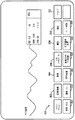
図1を参照すると、本発明による、患者監視システム100の好ましい実施の形態が概略的に示される。一般的に、システム100は、1つ又はそれ以上の入力装置105と、患者監視コンソール110と、該コンソール110に連結されたデータ入力装置115と、該コンソール110に連結された1つ又はそれ以上の出力装置とを含む。好ましい実施の形態において、患者監視コンソールは携帯型であり、下に説明される追加の特徴を組み込むように修正された、株式会社GEメディカル・システムズ・インフォメーション・テクノロジーのDASH(商標)3000プロ(商標)ブランドの携帯型監視装置を用いて実施される。
【0010】
入力装置105は、患者と連結可能な複数の電極E1,E2...ENを備える多重リードECGセンサを含む。電極は患者によって生成されたECG信号を獲得することができる。電極E1,E2...ENの数は多様であってよい。例えば、3、5、10又は12本のECDリードを用いることができる。好ましい実施の形態において、電極の数は10であり、リードは、12SL処理のための標準12本のリード形状により患者と連結される。
【0011】
電極E1,E2...ENは、インターフェースケーブル125によって、コンソール110に連結される。インターフェースケーブル125は、電極E1,E2...ENと入力ポート130との間に直通通信を提供する。入力ポート130は、ケーブル125上の対応する連結器と嵌合する連結器を備える。インターフェースケーブル125は、患者から獲得したECG信号をコンソール110へ伝達することを可能にする。インターフェースケーブル125は、受動ケーブルであることが好ましいが、これに代わって、ケーブル125はECG信号を(さらに下で説明される)ECGリードに増幅かつ組み合わせるための、能動回路配線を含むことができる。他の実施の形態において、電極E1,E2...ENは、無線周波数(「RF])信号を通常のRF受信器を通してコンソール110に連結された1つ又はそれ以上のアンテナに送信する、遠隔測定用送信器を通して、コンソール110と通信することができる。
【0012】
入力装置105は、さらに、患者に連結可能で、患者からの追加の生理的な信号を獲得する1つ又はそれ以上のセンサを含む。例えば、センサは侵襲性及び/又は非侵襲性血圧センサ141と、心拍酸素計測センサ142と、温度センサ143と、二酸化炭素センサ144と、呼吸センサ145と、心拍出量センサ146とを含むことができる。電極E1,E2...ENと同様に、及び図示の実施の形態において、センサ140は、各々の入力ポート150でインターフェースケーブル152によって、又は、上述の遠隔測定送信器を介して、コンソール110に連結することができる。
【0013】
追加のセンサもまた、コンソール110に連結される。例えば、多くの市販のセンサは、RS232リンクを介してデータを送信することができる。図1において、各々のRS232リンクは、データを複数の追加のセンサ155からインターフェース157に送信するのに用いることができ、インターフェース157は、データを連続的或いはネットワークリンクによって、コンソール110に再送信する。これらのセンサ155は、センサ141から145のセンサと同じ又は異なる種類のものとすることができる。
【0014】
センサ141から145からの入力信号は、コンソール110で、増幅及びフィルタ回路配線165と、アナログ・デジタル(A/D)変換回路配線170と、分析モジュール175によって処理される。センサ155がデータをコンソール110に与える方法に応じて、センサ155からの信号も、この回路配線の幾つか又はすべてによって処理することができる。増幅及びフィルタ回路配線165と、A/D変換回路配線170と、分析モジュール175は、離散回路配線であることも、集積回路(例えば、ある用途固有の集積回路)であることも、又はその両方の組み合わせであることもできる。
【0015】
増幅及びフィルタ回路配線165は、入力ポート130及び150から生理的な信号を受信し、その生理的な信号を増幅し、フィルタを通す(すなわち調整する)。例えば、増幅及びフィルタ回路配線165は、計装用増幅器180を含む。計装用増幅器180は、ECG信号を受信し、その信号を増幅し、フィルタを通して多重リードECGを作る。多重リードECGのリード数は、本発明の範囲を変更することなく、変えることができる。
【0016】
A/D変換回路配線170は、計装用増幅器180に電気的に連結される。A/D変換回路配線170は、増幅されフィルタを通した生理的な信号を受信し、その信号をデジタルの生理的な信号に変換する(例えば、デジタルの多重リードECG)。デジタルの生理的な信号は次に、A/D変換回路配線170に電気的に連結された分析モジュール175に与えられる。
【0017】
分析モジュール175は、デジタルの生理的な信号を読み取り、A/D変換回路配線170からの信号を分析し、その信号と結果として得られた分析をオペレータに表示する。分析モジュール175は、制御装置すなわちマイクロプロセッサ182と内部メモリ185とを含む。内部メモリ185は、ソフトウェアプログラムを格納するためのプログラム格納メモリ190と、データを格納するためのデータ格納メモリ195とを含む。マイクロプロセッサ182は、ソフトウェアプログラムを実行し、監視システム100を制御する。オペレータインターフェースを含むソフトウェアプログラムの実施形態は、さらに後で説明する。
【0018】
コンソール110は、電源装置196も含む。電源装置196は、電力をコンソール110に供給し、外部電源197又は内部電源198のいずれかから、入力電力を受ける。コンソール110は、ポート又はドッキングステーションを経て外部電源197と連結できることが好ましい。内部電源160は、充電式電池で、コンソール110がドッキングステーションによって受けられたときに、充電可能であることが好ましい。
【0019】
データ入力装置115は、オペレータ(例えば、技術者、看護士、医者等)がデータをコンソール110に入力することを可能にする。データ入力装置115は、コンソール110(例えば、ダイヤル制御装置)内に組み込むことができ、又はこれに代わって、独立型装置(たとえば独立型キーボード)であることもできる。他の例となるデータ入力装置115には、キーパッド、タッチスクリーン、位置指示装置(例えば、マウス、トラックボール)等が含まれる。
【0020】
出力装置120は、プリンタ201と、ディスプレイ装置202と、格納装置(例えば、磁気ディスク駆動装置、読み取り/書き込みCD−ROM等)203と、スピーカ204とを含むことが好ましく、それらのいずれか、又はすべては、コンソール110と一体に構成することができる。出力装置120は、さらに、中央監視装置205と、1つ又はそれ以上の追加の患者監視装置206を含む。患者監視システム100は、患者監視システムが配置される医療設備の通信インターフェース197と、医療通信ネットワークを経て、中央監視装置205と患者監視装置206に連結される。もちろん、他の出力装置(例えば除細動装置)を追加し又は取り付けることができ、及び/又は1つ又はそれ以上の出力装置をコンソール110内に組み込むことができる。さらに、すべての入力装置105及び出力装置120が、監視システム100の作動ために必要とされるわけではない。
【0021】
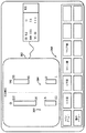
次に図2を参照すると、心拍出量センサ146がさらに詳細に示される。心拍出量センサ146は非侵襲性であり、心拍出量を測定するために、インピーダンス心拍記録法を用いることが好ましい。インピーダンス心拍記録法は、大動脈における血量及び胸部の流体体積の変化を見積もるために、胸郭の電気的インピーダンスの変化を利用する。胸郭の電気的インピーダンスの変化は、印加された電流に応じた電圧の変化を測定することによって、測定される。具体的には、励起信号が、電極221a及び221bと222a及び222bを用いている患者に印加される。電極221a及び221bは、首の両側に沿って、耳たぶの真下に垂直に配置される。上位の胸郭電極222a及び222bは、中央補助線に沿って胸部の両側の上の剣状突起と一致するように配置される。電極221a及び221bは、電極222a及び222bと同様に、互いに正反対の位置に配置される。励起信号は低振幅(例えば1から4ミリアンペア)で、高周波数(例えば、30から100kHz)で、一定振幅の交流が胸郭に印加される。
【0022】
血流を示す応答信号は、励起信号に応じて生成される。応答信号は、現在首上に注入されている電極221a及び221bの下の、別の一対の電極223a及び223bと、現在下方胸部上に注入されている電極222a及び222bの上の、別の一対の電極224a及び224bとによって獲得される。一定振幅の電流が胸郭に印加されるとき、応答信号の電圧は、電極223a及び223bと、電極224a及び224bとの間のインピーダンスに比例する。このインピーダンスは、患者の心臓を通る血流路における血量の関数である。
【0023】
したがって、図2の実施の形態において、胸郭の全インピーダンスZ(t)は、随時、全体の胸郭のインピーダンスZ0と、循環及び脈動性の血流の両方に対応するインピーダンスの変化ΔZの和に等しい。即ち、
Z(t)=Z0+ΔZ(t)
全体の胸郭のインピーダンスZ0は、心筋及び骨格筋、脂肪、肺、骨、維管束組織及び胸部における液体に対する空気の比率を含む、胸部の種々の組織のインピーダンスによって求められる。循環及び脈動性の血流の両方に対応するインピーダンスの変化ΔZは、血液が高導電性であるという事実からもたらされる。したがって、血量は胸大動脈において増加し、それより少ない程度で、肺動脈においては、電流に対するインピーダンスの減少を生じると推測される。脈動間の動的インピーダンス(ΔZ(t))は、実際上は、心室の吐出によるインピーダンスの変化である。呼吸によって引起されたインピーダンスは、その振幅がより大きく、周波数がより低いため、電子的フィルタ技術を用いて取り除くことができる。図2の実施の形態における心拍出量センサ146は、カリフォルニア92121、サンディエゴ6175ナンシーリッジドライブのカーディオダイナミクス社によって製造されたものである。
【0024】
次の表は、監視システム100によって測定された心拍出量(表1)、又は計算された心拍出量(表2)に関する、例示的なパラメータを説明するものである。
【0025】
【表1】

【表2】
表2において、VEPTは電気的に関与している組織の量(身長、体重及び性別に影響を受ける胸部の大きさについて誘導される量)であり、TFLは基線胸郭のインピーダンスZ0である胸郭の流体指数であり、dZ/dtMAXはΔZの一次微分値の最大であり、d2Z/d2tMAXはΔZの二次微分値の最大であり、BSAは体表面積であり、CVPは中心静脈圧であり、PAWPは肺動脈楔入圧であり、B点は大動脈弁の開口部であり、X点は大動脈弁の閉鎖部である。MAP(平均動脈圧又は動脈的又は大腿部の侵襲性血圧の読み込みからくる平均圧)、PAWP、SpO2(心拍酸素計測値)、及びHb(ヘモグロビン)は、個々の心拍出量パラメータの計算に用いられる血流力学の入力データである。表2におけるパラメータは分析モジュール175によって計算される。
【0028】
次に図3から図19を参照すると、心拍出量情報を監視し、表示することを助けるオペレータ・インターフェースが示される。最初に図3を参照すると、最上位の画面ディスプレイ240が示される。画面ディスプレイ240は、複数の情報領域と、複数の波形と、複数のパラメータウィンドウとを備える。情報領域は、ケアユニットを表示する領域242と、ベッド番号を表示する領域244と、患者名を表示する領域246と、日時を表示する領域248とを含む。複数の波形はECG波形250と、心拍出量波形252と、CO2波形254と、他の波形とを含む。
【0029】
パラメータウィンドウは、画面ディスプレイの右端に表示され、必要なときには下部を横切って表示される。表示されるパラメータウィンドウの数は、患者監視システム100に連結されたセンサの数による。すべての監視されたパラメータは、パラメータウィンドウを有することが好ましい。図3において、パラメータウィンドウは、ECGウィンドウ260と、NBP(非侵襲性血圧)ウィンドウ262と、ART(侵襲性動脈圧読み込みによる血圧)ウィンドウ264と、ICG(インピーダンス心拍記録又は心拍出量)ウィンドウ266と、SPO2ウィンドウ268と、CO2(二酸化炭素)ウィンドウ270と、警報ウィンドウ272と、温度ウィンドウ274とを含む。パラメータ表記は、ディスプレイのレイアウト及び監視されているパラメータの数によって、異なる大きさで表示することができる。パラメータウィンドウは、2倍の高さの大きさ(ECGパラメータウィンドウ260のように)、標準の大きさ(残りのパラメータウィンドウ262から274のように)、小さくされた大きさ(図示せず)であることができる。各々のパラメータウィンドウは2つの部品を有し、それはパラメータ表記部分276と測定値部分278である。各々のパラメータウィンドウ260から274は1つの1次パラメータと、3つの2次パラメータとを表示する。制限及び測定単位もまた、パラメータ表記の下で表示されることができる。
【0030】
例えば、ICGパラメータウィンドウ266は、インピーダンス波形252についての信号品質280指示器と併せて、表1及び表2において識別された16のパラメータのうちの4つを表示する。ICGパラメータウィンドウ266は、1つの大きな1次サブパラメータ値と、3つの他の2次サブパラメータとを有し、そのすべては表示用に選択可能である。選択可能なサブパラメータは、表1及び表2に示されたもののいずれでもよい。信号品質指示器280は、値の正しさについての信頼性を反映する、1つから3つまでの星印を備える。3つの星印は高い信頼性、2つの星印は平均的な信頼性、1つの星印は低い信頼性を表す。標準的な監視中、パラメータウィンドウ266における値は、周期的に更新される(例えば2秒毎)。
【0031】
主要なオペレータ制御は、ダイヤル入力装置であることが好ましい。ダイヤル入力装置は、パラメータ表記とメニューオプションを強調表示するためにいずれの方向にも回転する。所望の選択が強調表示された後、ダイヤル入力装置がオペレータによって押され、新しいメニュー又は小さなポップアップメニューを見ることができる。したがって、オペレータはダイヤル入力装置を用いて、図3に示されるメインメニューから適切なパラメータ表記を選択することによって、パラメータメニューにアクセスする。オペレータは、追加メニューオプションを選択することによって、他のメニュー(特定のパラメータに関係しない)にもアクセスすることができる。
【0032】
IGCウィンドウ266が強調表示され、オペレータがダイヤル入力装置を押したとき、図4に示される最上位のIGCメニュー300が表示される。最上位のICGメニュー300は、患者情報ボタン302と、早見ボタン304と、2次パラメータボタン306と、制限ボタン308と、傾向ボタン310と、ヘルプボタン312と、波形ボタン314と、速度ボタン316と、信号品質ボタン318と、脈動平均ボタン320と、正常範囲変更ボタン322と、リード確認ボタン324とを備える。
【0033】
すべての利用可能なメニューオプションは、強調表示されている現在の選択と共に表示される。幾つかの場合においては、ダイヤル入力装置が選択を変更するために、回転可能(又はスクロール可能)であることを示す矢印も強調表示される。ダイヤル入力装置が回転されるとき、新しい選択が強調表示され、オペレータはダイヤル入力装置を押し、特定のメニューオプション(すなわちボタン)を選択することが可能となる。データ入力装置115がビデオディスプレイ202と一体のタッチスクリーンである場合、ボタン302から324は、オペレータがビデオディプレイ202上の適切な場所を押すことによって作動させることができる。しかしながら、ボタン302から324は、単にボタンとして表示されるだけであって、それよりはむしろダイヤル入力装置によって作動させられるものであることが好ましい。
【0034】
患者情報ボタン302を選択して、オペレータの入力が受信されたとき、患者情報メニュー330は図5に示されるように表示される。患者情報メニュー330は、オペレータに患者情報を入力するように促す情報表示ウィンドウ332を含む。心拍出量監視には、身長、体重、性別、年齢の4つの主要な患者人口統計値が用いられる。追加の情報は、特定のパラメータを監視するために用いられる。情報表示ウィンドウ332は、オペレータにMAP源(例えば、非侵襲性血圧又は動脈経路のいずれか)のオプションを選択するように促す。情報表示ウィンドウ332は、さらに、オペレータにCVPについての値を手動で入力することを促し、又はこれに代わって、システム100が非侵襲性CVP値を用いることを可能にさせる。情報表示ウィンドウ332は、さらに、オペレータにPAW(肺動脈楔入圧)値を入力することを促し、又はこれに代わって、システム100が非侵襲性PAWセンサをこの情報源として用いることを可能にさせる。最後に、情報表示ウィンドウ332は、オペレータにHb(ヘモグロビン)値を入力することを促す。情報ウィンドウ332は画面ディスプレイの上方左部分の上に重ねられる。以下に説明されるように、ヘルプオプションが、あるメニューオプションと共に選択されたとき、情報ウィンドウが表示される。情報ウィンドウは指示情報又は他のリアルタイムでない時間情報を含む。
【0035】
早見ボタン304を選択して、オペレータの入力が受信された場合、早見メニュー340が、図6に示されるように、オペレータに表示される。早見メニュー340は、オペレータに、情報ウインドウ342における心拍出量パラメータデータの包括的なリストを素早く見せることを可能にする。
【0036】
前に説明されたように、矢印344は、正常範囲、測定単位及び戻るの間の選択を変更するために、ダイヤル入力装置が回転可能であることを示す。ダイヤル入力装置が押されたとき、その変更が実施される。その後、ポップアップメニューは閉じられ、変更が事実上のものになる。
【0037】
図6において、心拍出量データは、情報表示ウィンドウ342における「測定単位」のフォーマットで表示され、心拍出量データは情報表示ウィンドウ342の領域346における測定単位と併せて表示される。心拍出量データは、さらに、「正常範囲」フォーマットにおいても格納することができ、情報表示ウィンドウ342は、図7に示されるように正常範囲と併せてICGデータを表示する。プラス(+)348又はマイナス(−)349は、特定された範囲の外にあるデータを表示するために用いられる。
【0038】
2次パラメータボタン306を選択して、オペレータ入力が受信された場合、2次パラメータメニュー350は、図8に示されるように表示される。2次パラメータメニュー350は、どのパラメータがICGパラメータウィンドウ266における2次パラメータとして表示されるかを、オペレータに選択させることを可能にする。表1及び表2による3つの2次パラメータが、表示されたリスト352に示され、パラメータウィンドウ366における表示のために選択されることができる。メニュー350は、オペレータがパラメータリストから3つの候補を選択することを可能にし、これらの候補は、次に、パラメータウィンドウ366に表示される。1次パラメータ位置に割り当てられたパラメータは、2次パラメータ表示に利用可能なパラメータのリストには含まれない。
【0039】
制限ボタン308を選択して、オペレータ入力が受信された場合、制限メニュー360が、図9に示されるように表示される。制限メニューは、TFC及びCIにおいての警報制限をオペレータが調整することを可能にする。上限及び下限は、両方のパラメータについて調整することができる。現在の制限設定が情報ウィンドウ362に示され、監視されている患者についてのパラメータの現在の値も、矢印364を用いて示される。値が上限と下限との間にあり続ける限り警報は鳴らない。制限を越えた場合に警報が鳴る。
【0040】
傾向ボタン310を選択して、オペレータ入力が受信された場合、心拍パラメータについての傾向情報は、表フォーマット又はグラフフォーマットで表示される。傾向は、1つのパラメータの特定時間に渡るグラフ表示である。すべての非偶発性のパラメータは、1分間に30回サンプリングされる。中間値が求められ、その値は1分間の分解能における傾向表示のために格納される。偶発性のパラメータ(NBP等)は、それが起こる度に格納される。いずれのパラメータの組み合わせも、オペレータ入力によって求められるように、傾向化されることができる。表1及び表2における心拍出量情報は、ECGデータ及びセンサ141から145及び155によって集められた他のすべての情報と併せて、傾向化することができる。
【0041】
ヘルプボタン312を選択して、オペレータ入力が受信された場合、ヘルプ情報ウィンドウ370、372、374が、図10から12に示されるように表示される。3つのヘルプ情報ウィンドウ370、372、374は、心拍出量設定及び監視のための情報を与える。項目には、皮膚の準備(ウィンドウ370、図10)と、適切なセンサの配置(ウィンドウ372、図11)と、トラブルシューティング問題(ウィンドウ374、図12)とが含まれる。
【0042】
波形ボタン314を選択してオペレータ入力が受信された場合、波形メニュー380が、図13に示されるように表示される。波形メニュー380は、オペレータに、心拍サイクルの事象と一致するインピーダンスにおける脈動間の変化を反映する波形、又はインピーダンス波形における変化率を反映するdZ/dt波形を選択するオプションを与える。選択された波形252は、ディスプレイ240上の波形領域に表記される。心拍出量波形252は、波形メニュー380を用いてターンオン又はターンオフすることができる。図13において、表示された波形は、矢印382によって表示されるように、インピーダンス波形である。
【0043】
速度ボタン316を選択してオペレータ入力が受信された場合、速度メニュー390が、図14に示されるように表示される。速度メニュー390は、表示された心拍出量の波形252についての掃引速度を選択するために用いられる。図14において、選択された速度は、矢印392によって表示されるように、25ミリメートル/秒である。
【0044】
信号品質ボタン318を選択してオペレータ入力が受信された場合、信号品質メニュー400が、図15に示されるように表示される。起動後、分析モジュール175は、最適なデータ獲得及びデータ処理のための最善の信号であると考えられるものを選択する。信号品質メニュー400は、オペレータにこのプロセスを手動で優先することを可能にさせる。メニュー400は、オペレータに、自動検索と信号1から信号4までを含む選択肢を与える。オペレータが自動検索を選択した場合、システム100は新しい最適な信号を探す。オペレータが信号1から信号4までを選択した場合、システム100は選択された信号を使用する。
【0045】
オペレータが脈動平均ボタン320を選択した場合、脈動平均メニュー410が図16に示されるように表示される。脈動平均メニュー410は、データ更新のために平均化された脈動数をオペレータが選択することを可能にする。脈動平均の選択肢は、5、10、20、30、60の脈動である。脈動平均の数は小さければ小さいほど、データはアーチファクトによって影響を受ける。平均化された脈動の高い数は、最小の変動を持つ獲得されたデータを平滑化する。
【0046】
オペレータが正常範囲変更ボタン322を選択した場合、正常範囲変更メニュー420が図17に示されるように表示される。正常範囲変更メニュー420は、オペレータが心拍流パラメータの正常範囲を変更することを可能にする。デフォルトの正常範囲は、情報ウィンドウ422に表示される。デフォルトの正常範囲は、主治医の医療的な判断によって変更することができる。
【0047】
オペレータがリード確認ボタン324を選択した場合、電極221a及び221b、222a及び222b、223a及び223b、224a及び224bのリードチェックが、図18に示されるように開始される。心拍流パラメータを監視しているとき、電極は周期的にリードの破損状況についてチェックされている。リード確認プロセス中、心拍流の波形は、ほぼ0.5秒間平地線432を示し、「リード確認」のメッセージが表示される(434)。リード確認メニューオプションは、システム100が、オペレータ入力に応じてリードの破損状況についてチェックすることを可能にする。監視装置がリードの破損状況を感知したときには、破損したリードの位置を示すメッセージが、図19におけるメッセージ436によって示されるように表示されることができる。
【0048】
次に図20を参照すると、作動中及びシステム初期化後において、監視システム100は、ステップ450において入力装置105(電極E1,E2...EN及びセンサ141から145、155)を用いて、連続的に患者からの生理的な信号を獲得する。ステップ452において、分析モジュールは患者からの生理的な信号を処理する。ステップ456において、処理されたデータはオペレータに表示される。
【0049】
図21は、1つの好ましい作動方法における心拍出量データに関連させて本プロセスを示す。すなわち、ステップ450a(ステップ450に対応する)において、監視システムは電極221a及び221b、222a及び222bを用いて、励起信号を患者に印加する。励起信号は低振幅(例えば、1から4ミリアンペア)、高周波数(例えば、30から100kHz)、胸郭体積に印加される一定振幅の交流である。ステップ450b(同様にステップ450に対応する)では、応答信号が電極223a及び223b、224a及び224bを用いて獲得される。応答信号は血流を示し、励起信号に応じて生成される。特に、応答信号の電圧は、電極223a及び223bと224a及び224bとの間のインピーダンスに比例し、逆に、インピーダンスは、患者の心臓を通る血流における血量の関数である。応答信号は信号の応答特徴を励起信号に示し、心臓のインピーダンスを測定するために使用可能である。
【0050】
ステップ452a及び452b(ステップ452に対応する)では、分析モジュール175が応答信号を処理して心拍出量に関する値を生成する。好ましい実施の形態において、ステップ452aでは、応答信号が電気的にフィルタされ、呼吸によって引き起こされたインピーダンス変化を取り除く。ステップ452bでは、表1及び表2に示された方程式が次に分析モジュール175によって実行され、表1及び表2に示された心拍出量に関する16の好ましい値を生み出す。
【0051】
ステップ454は、図21に示される追加のステップである。ステップ454において、心拍出量情報は、携帯型の患者監視システム100が配置されている医療設備の局所情報通信ネットワーク210を経て、患者監視システム100から遠隔患者監視装置に送信される。これにより、ステップ456a(ステップ456に対応する)では、心拍出量情報を遠隔患者監視装置205、206のディスプレイ上に表示することを可能にする。したがって、医者又は看護士は、患者の部屋の外で他の仕事に従事しながらも、患者の状態を監視することができる。もちろん、心拍出量情報もまた、分析モジュールに直接連結されたディスプレイ202で表示されることができる。
【0052】
患者監視システム100は、さらに、他のセンサからの情報も処理する。例えば、ECG監視に関連して、12SL監視が実行される。図示の実施の形態においては、10本の電極が、ECG信号を連続的に患者(RA、LA、LL、RL、V1、V2、V3、V4、V5、V6)から獲得するために用いられる。ECG信号はインターフェースケーブル125を介して、コンソール110の入力端末130に送信される。ECG信号110は、該ECG信号を組み合わせ、増幅し、フィルタに通す計装用増幅器180に与えられ、標準的な12本のリードを持つECGがもたらされる。結果として得られた多重リードECGは、多重リードECGを表示するデジタル信号を作るために多重リードECGの各々のリードをサンプリングし、かつ、デジタルの多重リードECGを分析モジュール175に与える、A/D変換回路170に与えられる。分析モジュール175に与えられた多重リードECGは、患者のリードから直接獲得されたI、II、V1、V2、V3、V4、V5、V6のECGリード、及びそれから引き出されたIII、aVR、aVF、aVLのリードを含む。
【0053】
分析モジュール175は、各々のリードを高周波数及び低周波数ノイズについて評価する、高周波数及び低周波数感知モジュールを含む不整脈分析モジュールと、生理的な帯域内にある信号を感知し、それを有効なECG信号として認識するQRS感知モジュールと、脈動形と共に次第に変化するように、段階的に更新されるアクティブなテンプレートのリストを通して、ECGデータを送るQRS相関モジュールとを含む。分析モジュール175は、さらに、QRS相関装置によって認識された脈動と、既存のテンプレートのいずれにも適合しない脈動とを処理し、新しいテンプレートを作りアクティブなテンプレートの最も役に立たないものを交換するかどうかの決定をする裁定モジュールを含む。これらの最小の周波数と適合されたり、又は最近適合又は分類されていないような、テンプレートになる予定のものは、アーチファクトになる確率が高い。分析モジュール175は、さらに、脈動に関するテンプレート情報を受信する分類モジュールを含み、すべての特徴と一時的な測定を取り込み、正常QRS、心房性人工脈拍調整正常QRS、上室性期外収縮QRS、上室性人工脈拍調整正常QRS、上室性期外収縮QRS、T波、P波、心室性人工脈拍調整スパイク、心房性人工脈拍調整スパイク又はアーチファクト、のような特定の脈動によって表される決定に達する。個々の脈動特徴を求めるためになされる測定は、R振幅、S振幅、QRS極性、T波極性、ST区間、雑音レベル、PR間隔、P波の存在、QT間隔、QRS持続時間、RR間隔、RR間隔変化、脈拍調整器信号、心拍ベクトルの回転である。分析モジュールは、さらに、不整脈警告をするための周知の基準を用いる、不整脈警告論理モジュールを含む。これらは、使用可能なECGデータ持続時間、心拍数、QRS群間の時間、再分極期間内の心室波形の発生、非心室脈動によって進行又は追随される1つ又はそれ以上の心室脈動の発生、あらかじめ決められた大きさのST偏位、R間の間隔、及びQRS群と脈拍調整器スパイクとの間の間隔とを含む。この情報によって、不整脈警告論理は、アーチファクト、心室不全収縮、心室細動、心室性頻脈、カプレット、二段脈、加速した心室律動、一時停止、三段脈、分離した心室性期外収縮波形、ST偏位、頻脈、徐脈、不整脈、或いは電子脈拍調整器の不感知、の中の1つが起きたかどうかを判断することができる。不整脈警告が示された場合、適切な警報信号がディスプレイ202に与えられる。
【0054】
作動において、分析モジュール175は、ECGリードI、II、III、V1からV6、aVF、aVR及びaVLを受信する。最初、脈動選択部は各々のリードについてテンプレートを作る。この時点以降、QRS選択装置は同じ形状を探す。適合する形を見出した場合、プログラムはそれを別のQRS感知として分類する。さらに、プラグラムは最適に適合するものを探しながら、互いを経て波形を摺動させる。獲得モジュールにおけるフィルタの出力があらかじめ選択された値を超えるが、適合するものがない場合、異なる脈動形式が感知されたとみなされ、テンプレートの追加の組がさらに別の適合テストのために作られる。したがって、脈動選択装置は、ECGの記録において起こるQRS群の形状毎に感知及びグループ化の両方を行うために、フィルタ及びテンプレート適合技術を用いる。QRS検知器はまた、最大相関、脈動形式の各々の脈動と位置及び時間を合わせるのに用いられることができるECG記録上の点を定義する。
【0055】
プログラムは次に、どの脈動形式が形態学測定に使用されるかを判断する。プログラムは、伝導系においてどの脈動が最も高いレベルの源を有するかを判断するために、RR間隔と、いずれの調整器のスパイクの配置も用いる。同一のQRS形状は、期外収縮との洞律動の場合のように細分されることさえ出来る。この選択は、脈動形式毎の脈動数に左右されるのではなく、分析のために最も参考になる脈動形式に左右され、それは追求されるもので、3つ又はそれ以上の波形を備える如何なる脈動もその資格を持つことができる。常伝導に最も参考になるとコンピュータが考える脈動形式は、多くの場合、1次脈動と呼ばれる。
【0056】
1次脈動が選択された後、各々のそれに関連する脈動が、各々のリードについて代表的な群を生成するために用いられる。これは、QRS検知器によって生成されたサンプル時間を用いて行われる。これらの時間はQRSの発生を示すだけでなく、特定の脈動形式についてのQRSが最適に適合したときも示す。代表的な群は、次に、脈動の位置合わせされたグループ、すなわち各々のサンプル時間で重ねられた脈動の中間電圧をとることによって形成されたものからの中央電圧によって生成される。
【0057】
12本のリードの各々について1次サイクルの中央値が確立された後、各々の群が識別される。これは、各々のリードについて別々に行われる。プログラムは、信号が各々の群内で基線を横切る点を見出す。その横切る点が、あらかじめ決められた値よりも大きな領域を有する波を定義する場合、その波は重要であると考えられる。その領域がこの値よりも少ない場合、プログラムはその波が重要ではないと考え、別々の波として分類しない。測定マトリックスは、P、P’、Q、R及びS波の振幅及び持続時間と、T波の振幅と、PR及びQTの休止時間と、QRSの持続時間と、STJ、STM及びSTEの振幅とを含む、個々の波のすべてに対する、QRSの開始に対する振幅と持続時間とを含む。
【0058】
プログラムは、次に解釈をするにあたってこれらの測定を利用する。これには、律動分析と形態学解釈が含まれる。律動分析は最初に、サンプルにおける卓越律動の源を求め、電子心房脈拍調整、心房粗動、異所性心房律動、洞律動、接合部律動及び心房細動からなる主要なカテゴリーから選択する。
【0059】
形態学解釈は、ウォルフ−パーキンソン−ホワイト、心房肥大、低電圧QRS、呼吸器系統の病気パターン、QRS軸、伝導異常、心室肥大、梗塞形成、心室肥大を伴うST+T異常、古くなりかけた梗塞、心外膜障害、心膜炎、早期再分極、非特異的ST上昇、心内膜下障害、非特異的ST機能低下、ジギタリス効果、接合部ST機能低下、虚血、QRS−T角及びQT間隔のようなQRS異常の存在を求める。
【0060】
他の監視用アプリケーションが心拍出量監視のために同様に行われる。したがって、血圧センサ141からの血圧情報、心拍酸素計測センサ142からの心拍酸素計測値情報、温度センサ143からの温度情報、二酸化炭素センサ144からの二酸化炭素情報、及び呼吸センサ145からの呼吸ガス情報が、獲得、処理され、ディスプレイ202でローカルに表示されるか、又は別のディスプレイで遠隔的に表示される。すべてのデータはまた、プリンタ201によって印刷され、分析又は後の呼び戻しのためにデータ格納メモリ195に格納され、格納のために外部格納装置203に与えられ、及び/又は病院の通信ネットワークを経て患者監視システムに連結される遠隔装置205及び206に提供されることができる。
【0061】
図22を参照すると、患者監視ネットワーク500が示され、その部品の幾つかは前に説明されたものである。患者監視ネットワーク500は、病院の通信ネットワーク210と、複数の患者監視システム206(前述のような患者監視システム100と同じ方法で構成されることが好ましい)及び中央監視装置205とを備える。病院の通信ネットワークはベッド間の通信を確立し、患者のデータが中央監視装置205に送られることを可能にする。心拍出量データを含む患者データは、病院の通信ネットワーク210の上で通信されることができ、患者監視装置205及び206は、他の患者監視装置から獲得したデータを見て、傾向化することができる。警報もネットワーク210上で送信することができる。
【0062】
遠隔視を可能にするために、図3における追加メニューボタン275を経て実現可能であることが好ましいメニュー選択の1つは、他の患者を見るオプションである。他の患者を見るオプションは、オペレータが、病院の通信ネットワーク210上の如何なる患者監視システムも選択し、特定の監視システム100で見ることを可能にさせる。ローカルには、ディスプレイ画面は次に、半分に分けられ、ある患者からのデータは画面の半分に、及び他の患者からのデータは画面のもう一方の半分に表示される。心拍出量波形及びパラメータのような、連続的な波形及びパラメータ値データは両方の患者について表示される。
【0063】
前に説明されたように、コンソール110は携帯型であることが好ましい。コンソール110は、例えば、持ち手を備え、20ポンドより少ない重さであることができ、又は15ポンドより少ないことが好ましく、約12ポンドであることが最も好ましい。各々の患者監視システム100及び206は、患者監視コンソール110を受けることができ、コンソールを電力と病院の通信ネットワーク210に連結する、ドッキングステーションを含むことが好ましい。さらに、通信インターフェース197は、患者監視システム100と病院の通信ネットワーク210との間の無線通信リンクを確立することができる。
【0064】
携帯性を可能にするために、病院の通信ネットワーク210は、複数のアクセス点505を含み、オペレータがネットワークへの接続を維持しながら、あるアクセス点505から別の点へ移動することを可能にする。アクセス点505は、患者監視システム100及び206を病院の通信ネットワーク210に連結し、ネットワークの有線部分と無線部分との間の橋として働く。各々のアクセス点505によって網羅された領域は、連続的な網羅を確実にするために、重複している。監視システム100は、配線(ドッキングステーション又はケーブル接続)及び無線ネットワーク通信との間を自動的に切り換える。
【0065】
本患者監視システムの好ましい実施の形態は、幾つかの利点を提供する。第一に、コンソール110が携帯型である。これにより、患者が緊急治療室から患者の次の移動場所に移送されている間の監視が可能になる。さらに、コンソール110は心拍出量だけでなく、12本のリードを持つECG及び他のパラメータも監視する。したがって、医療関係者は彼らの監視のすべてを行うのに、別々の心拍出量監視装置と併せた患者監視装置の代わりに、1つの装置だけが必要となる。さらに、12本のリード分析及び他のECG分析は、単一の監視装置によって行うことができる。ベッドサイドの隙間は狭く、1ユニットだけ購入することが病院にとって経済的なため、これは重要なことである。さらに、心拍出量データは他のすべてのパラメータデータと併せて傾向化されることができる。これにより、臨床医らは心拍出量パラメータの変化を、時間をかけて監視された他のすべてのパラメータと平行して比較することが可能になる。正しい診断は、多くの場合、1つのパラメータだけを見るだけでなく、すべてのパラメータデータを考慮する必要があるため、これは重要である。通常、1つのパラメータにおける変化は、他のパラメータにおける変化も示し、医療関係者は、患者の治療を評価するとき、これらすべての変化を考慮することを望む。
【図面の簡単な説明】
【図1】 本発明の好ましい実施の形態による患者監視システムの概略図。
【図2】 図1の患者監視システムにおいて用いられる、好ましい非侵襲性心拍出量センサについての電極配置を示す図。
【図3】 図1の患者監視システムのディスプレイによって表示される最上位メニュー。
【図4】 図1の患者監視システムのディスプレイによって表示される心拍出量の最上位メニュー。
【図5】 図1の患者監視システムのディスプレイによって表示される患者情報メニュー。
【図6】 心拍出量データが測定単位フォーマットにおいて表示される、図1の患者監視システムのディスプレイによって表示される早見メニュー。
【図7】 心拍出量データが正常範囲フォーマットにおいて表示される、図1の患者監視システムのディスプレイによって表示される早見メニュー。
【図8】 図1の患者監視システムのディスプレイによって表示される2次パラメータメニュー。
【図9】 図1の患者監視システムのディスプレイによって表示される制限メニュー。
【図10】 図1の患者監視システムのディスプレイによって表示される異なるヘルプ情報ウィンドウを備えるヘルプメニュー。
【図11】 図1の患者監視システムのディスプレイによって表示される異なるヘルプ情報ウィンドウを備えるヘルプメニュー。
【図12】 図1の患者監視システムのディスプレイによって表示される異なるヘルプ情報ウィンドウを備えるヘルプメニュー。
【図13】 図1の患者監視システムのディスプレイによって表示される波形メニュー。
【図14】 図1の患者監視システムのディスプレイによって表示される速度メニュー。
【図15】 図1の患者監視システムのディスプレイによって表示される信号品質メニュー。
【図16】 図1の患者監視システムのディスプレイによって表示される脈動平均メニュー。
【図17】 図1の患者監視システムのディスプレイによって表示される正常範囲変更メニュー。
【図18】 図1の患者監視システムのディスプレイによって表示されるリード確認メニュー。
【図19】 破損したリード状況が感知された、図18に対応するリード確認メニュー。
【図20】 図1の患者監視システムの好ましい作動を示すフロー図。
【図21】 図1の患者監視システムの好ましい作動を示すフロー図。
【図22】 他の監視装置とネットワーク化された患者監視システムを示すブロック図。
【符号の説明】
100 患者監視装置
105 多重リードECGセンサ
110 患者監視コンソール
115 データ入力装置
125 インターフェースケーブル
130 入力端末
141 血圧センサ
142 SpO2センサ
143 温度センサ
144 CO2 センサ
145 呼吸センサ
146 心拍出量センサ
150 入力ポート
152 インターフェースケーブル
155 追加のセンサ
157 インターフェース
165 増幅器及びフィルタ器
170 アナログ・デジタル変換器
175 分析モジュール
180 計装用増幅器
182 マイクロプロセッサ
185 内部メモリ
190 プログラム格納メモリ
195 データ格納メモリ
196 電源装置
197 外部電源
197 通信インターフェース
198 内部電源
201 プリンタ
202 ビデオディスプレイ
203 外部格納データ
204 スピーカ
205 中央監視装置
206 患者監視装置
210 局所情報通信ネットワーク[0001]
BACKGROUND OF THE INVENTION
The present invention relates to a patient monitoring apparatus system and method, and more particularly to a patient monitoring system and method for non-invasively monitoring a patient's cardiac output.
[0002]
BACKGROUND OF THE INVENTION
There is an ongoing need for medical devices and procedures that allow for quick and accurate diagnosis of patient conditions. For example, in the context of myocardial infarction, patients often complain of chest pain and reach an emergency room in a hospital. Chest pain may indicate that the patient has symptoms of having a myocardial infarction or instead has a less severe condition such as heartburn or dyspepsia It may be. Statistics show that quickly finding out if a patient has a myocardial infarction and dealing with such a situation can minimize damage to the heart. Thus, there is a continuing need for a system that can be used to quickly find out if a patient has had a myocardial infarction.
[0003]
In addition, in the context of congestive heart failure, patients benefit from the use of intermittent muscle contraction infusions such as milrinone. These infusions are usually useful but expensive and have associated risks such as rhythm irregularities and effects from both indwelling instillation and pulmonary artery catheters used to demonstrate the need for muscle contraction support . Accordingly, there is a continuing need for a system that can be used to make preliminary determinations on patients scheduled for intermittent muscle contraction infusions to determine whether such infusions are necessary.
[0004]
Furthermore, in the context of circulatory defects, patients in emergency emergency rooms often have circulatory defects that ultimately lead to shock, organ weakness and death. Because early diagnosis is often difficult and subjective, these defects are therefore diagnosed at a later stage where treatment is currently ineffective. Diagnosing these circulatory defects early on allows the patient to be treated before these defects become unrecoverable. Thus, there is a continuing need for a system that can be used to help early detection of such circulatory defects.
[0005]
Cardiac output monitoring has been found to be useful in diagnosing such medical conditions. Impedance heart rate recording techniques for non-invasive monitoring of cardiac output are well known in the art. However, existing devices that can monitor cardiac output are cumbersome to use. Therefore, an improved patient monitoring system and method capable of monitoring cardiac output would be very beneficial.
[Patent Document 1]
US Pat. No. 5,956,033
[0006]
[Means for Solving the Invention]
According to one preferred aspect, an embodiment of a patient monitoring system comprises a non-invasive cardiac output sensor, a multi-lead electrocardiogram (ECG) sensor, and a patient monitoring console. The non-invasive cardiac output sensor can acquire a signal from the patient that indicates blood flow through the patient's heart. A multi-lead ECG sensor comprises a plurality of ECG electrodes capable of acquiring a plurality of ECG signals from a patient. The patient monitoring console includes an analysis module and a display. The analysis module is coupled to the non-invasive cardiac output sensor and the multi-lead ECG sensor and processes a signal from the patient indicative of blood flow to generate a value related to cardiac output. The display is coupled to the analysis module and displays values relating to cardiac output and an ECG waveform generated based on the ECG signal.
[0007]
According to another preferred aspect, an embodiment of a patient monitoring system comprises a non-invasive cardiac output sensor, a communication interface, and a patient monitoring console. The non-invasive cardiac output sensor can acquire a signal from the patient that indicates blood flow through the patient's heart. The communication interface may establish a communication link between the patient monitoring system and the local information communication network of the medical facility where the patient monitoring system is located. The patient monitoring console includes an analysis module and a display. The analysis module is coupled to a non-invasive cardiac output sensor and processes a signal from a patient indicative of blood flow to generate a value related to cardiac output. The display is coupled to the analysis module and displays a value relating to cardiac output. The communication interface can transmit a value related to cardiac output on the local information communication network.
[0008]
Other features and advantages of the invention will be apparent to those skilled in the art from consideration of the following detailed description, claims, and drawings.
[0009]
DETAILED DESCRIPTION OF THE INVENTION
Referring to FIG. 1, a preferred embodiment of a
[0010]
The
[0011]
Electrode E 1 , E 2 . . . E N Are connected to the
[0012]
The
[0013]
Additional sensors are also coupled to the
[0014]
Input signals from
[0015]
Amplification and
[0016]
The A / D
[0017]
The
[0018]
[0019]
[0020]
The
[0021]
Referring now to FIG. 2, the
[0022]
A response signal indicating the blood flow is generated according to the excitation signal. The response signal is another pair of
[0023]
Therefore, in the embodiment of FIG. 2, the total thorax impedance Z (t) is 0 And the sum of impedance changes ΔZ corresponding to both circulatory and pulsatile blood flow. That is,
Z (t) = Z 0 + ΔZ (t)
Overall thorax impedance Z 0 Is determined by the impedance of various tissues in the breast, including the ratio of air to fluid in the myocardium and skeletal muscle, fat, lung, bone, vascular tissue and breast. The change in impedance ΔZ corresponding to both circulatory and pulsatile blood flow results from the fact that blood is highly conductive. Accordingly, it is speculated that blood volume increases in the thoracic aorta, and to a lesser extent, in the pulmonary artery, it causes a decrease in impedance to current. The dynamic impedance (ΔZ (t)) between pulsations is actually a change in impedance due to ventricular ejection. The impedance caused by respiration can be removed using electronic filter techniques because of its greater amplitude and lower frequency. The
[0024]
The following table describes exemplary parameters for cardiac output measured by the monitoring system 100 (Table 1) or calculated cardiac output (Table 2).
[0025]
[Table 1]
[Table 2]
In Table 2, VEPT is the amount of electrically involved tissue (the amount induced for the size of the chest affected by height, weight and sex), and TFL is the impedance Z of the baseline thorax. 0 Thoracic fluid index, dZ / dtMAX is the maximum of the first derivative of ΔZ, d 2 Z / d 2 tMAX is the maximum of the second derivative of ΔZ, BSA is the body surface area, CVP is the central venous pressure, PAWP is the pulmonary artery wedge pressure, B point is the opening of the aortic valve, X point Is the closure of the aortic valve. MAP (mean arterial pressure or mean pressure from reading arterial or thigh invasive blood pressure), PAWP, SpO2 (cardiac oxygen measurement), and Hb (hemoglobin) are calculated for individual cardiac output parameters. It is the input data of the hemodynamics used for. The parameters in Table 2 are calculated by
[0028]
Referring now to FIGS. 3-19, an operator interface is shown that assists in monitoring and displaying cardiac output information. Referring initially to FIG. 3, a
[0029]
The parameter window is displayed at the right edge of the screen display and is displayed across the bottom when necessary. The number of parameter windows displayed depends on the number of sensors connected to the
[0030]
For example, the
[0031]
The primary operator control is preferably a dial input device. The dial input device rotates in either direction to highlight parameter notations and menu options. After the desired selection is highlighted, the dial input device can be pressed by the operator to see a new menu or a small pop-up menu. Therefore, the operator uses the dial input device to access the parameter menu by selecting the appropriate parameter notation from the main menu shown in FIG. The operator can also access other menus (not related to specific parameters) by selecting additional menu options.
[0032]
When the
[0033]
All available menu options are displayed with the current selection highlighted. In some cases, an arrow is also highlighted to indicate that the dial input device is rotatable (or scrollable) to change the selection. When the dial input device is rotated, the new selection is highlighted and the operator can press the dial input device to select a particular menu option (ie, button). If the
[0034]
When the
[0035]
When the
[0036]
As previously described,
[0037]
In FIG. 6, the cardiac output data is displayed in the format of “measurement unit” in the
[0038]
If the
[0039]
If the
[0040]
When the
[0041]
When the
[0042]
When the
[0043]
When the
[0044]
If the
[0045]
When the operator selects the
[0046]
When the operator selects the normal
[0047]
When the operator selects the
[0048]
Referring now to FIG. 20, during operation and after system initialization, the
[0049]
FIG. 21 illustrates the process in relation to cardiac output data in one preferred method of operation. That is, in
[0050]
In
[0051]
Step 454 is an additional step shown in FIG. In
[0052]
The
[0053]
The
[0054]
In operation, the
[0055]
The program then determines which pulsation type is used for the morphometric measurement. The program uses the RR interval and the placement of any regulator spike to determine which pulsations in the conduction system have the highest level source. The same QRS shape can even be subdivided as in the case of sinus rhythm with extrasystoles. This selection does not depend on the number of pulsations per pulsation type, but on the pulsation type that is most helpful for analysis, which is pursued, and any pulsation with three or more waveforms. Can also have that qualification. The type of pulsation that the computer considers most useful for normal conduction is often called primary pulsation.
[0056]
After the primary pulsation is selected, each and its associated pulsations are used to generate a representative group for each lead. This is done using the sample time generated by the QRS detector. These times not only indicate the occurrence of QRS, but also indicate when the QRS for a particular pulsation type is optimally matched. A representative group is then generated by the median voltage from the aligned group of pulsations, i.e. those formed by taking the intermediate voltage of the pulsations superimposed at each sample time.
[0057]
After the median of the primary cycle is established for each of the 12 leads, each group is identified. This is done separately for each lead. The program finds the point where the signal crosses the baseline within each group. A wave is considered important if it defines a wave whose crossing point has a larger area than a predetermined value. If the region is less than this value, the program considers the wave not important and does not classify it as a separate wave. The measurement matrix includes P, P ′, Q, R, and S wave amplitudes and durations, T wave amplitudes, PR and QT pause times, QRS durations, STJ, STM, and STE amplitudes. Including the amplitude and duration for the onset of QRS for all of the individual waves.
[0058]
The program uses these measurements for the next interpretation. This includes rhythm analysis and morphological interpretation. Rhythm analysis first determines the source of the dominant rhythm in the sample and selects from the main categories consisting of electronic atrial pulse adjustment, atrial flutter, ectopic atrial rhythm, sinus rhythm, junction rhythm and atrial fibrillation.
[0059]
Morphological interpretation includes: Wolf-Parkinson-White, atrial hypertrophy, low voltage QRS, respiratory disease pattern, QRS axis, conduction abnormalities, ventricular hypertrophy, infarct formation, ST + T abnormalities with ventricular hypertrophy, aging infarctions, Epicardial disorder, pericarditis, early repolarization, nonspecific ST elevation, subendocardial disorder, nonspecific ST function decline, digitalis effect, junction ST function decline, ischemia, QRS-T angle and QT Find the presence of QRS anomalies such as intervals.
[0060]
Other monitoring applications are similarly performed for cardiac output monitoring. Therefore, blood pressure information from the
[0061]
Referring to FIG. 22, a
[0062]
One of the menu choices that is preferably possible via the
[0063]
As previously described,
[0064]
To enable portability, the
[0065]
The preferred embodiment of the patient monitoring system provides several advantages. First, the
[Brief description of the drawings]
FIG. 1 is a schematic diagram of a patient monitoring system according to a preferred embodiment of the present invention.
FIG. 2 is a diagram illustrating electrode placement for a preferred non-invasive cardiac output sensor used in the patient monitoring system of FIG.
FIG. 3 is a top-level menu displayed by the display of the patient monitoring system of FIG.
4 is a top-level menu of cardiac output displayed by the display of the patient monitoring system of FIG.
FIG. 5 is a patient information menu displayed by the display of the patient monitoring system of FIG.
FIG. 6 is a quick look menu displayed by the display of the patient monitoring system of FIG. 1 in which cardiac output data is displayed in a unit of measure format.
FIG. 7 is a quick look menu displayed by the display of the patient monitoring system of FIG. 1 in which cardiac output data is displayed in a normal range format.
8 is a secondary parameter menu displayed by the display of the patient monitoring system of FIG.
FIG. 9 is a restriction menu displayed by the display of the patient monitoring system of FIG.
FIG. 10 is a help menu with different help information windows displayed by the display of the patient monitoring system of FIG.
FIG. 11 is a help menu with different help information windows displayed by the display of the patient monitoring system of FIG.
12 is a help menu with different help information windows displayed by the display of the patient monitoring system of FIG.
13 is a waveform menu displayed by the display of the patient monitoring system of FIG.
14 is a speed menu displayed by the display of the patient monitoring system of FIG.
FIG. 15 is a signal quality menu displayed by the display of the patient monitoring system of FIG.
16 is a pulsation average menu displayed by the display of the patient monitoring system of FIG.
FIG. 17 is a normal range change menu displayed by the display of the patient monitoring system of FIG. 1;
FIG. 18 is a lead confirmation menu displayed by the display of the patient monitoring system of FIG.
FIG. 19 is a lead confirmation menu corresponding to FIG. 18 in which a broken lead situation is detected.
20 is a flow diagram illustrating a preferred operation of the patient monitoring system of FIG.
FIG. 21 is a flow diagram illustrating a preferred operation of the patient monitoring system of FIG.
FIG. 22 is a block diagram illustrating a patient monitoring system networked with other monitoring devices.
[Explanation of symbols]
100 Patient monitoring device
105 Multiple Lead ECG Sensor
110 Patient monitoring console
115 Data input device
125 interface cable
130 Input terminal
141 Blood pressure sensor
142 SpO2 sensor
143 Temperature sensor
144 CO2 sensor
145 breath sensor
146 Cardiac output sensor
150 input ports
152 Interface cable
155 Additional sensors
157 interface
165 Amplifier and filter
170 Analog to digital converter
175 Analysis module
180 Instrumentation amplifier
182 Microprocessor
185 internal memory
190 Program storage memory
195 Data storage memory
196 Power supply
197 External power supply
197 Communication interface
198 Internal power supply
201 Printer
202 video display
203 Externally stored data
204 Speaker
205 Central monitoring device
206 Patient monitoring device
210 Local information communication network
Claims (13)
(A)患者の心臓を通る血流を示す患者からの信号を獲得することができる非侵襲性心拍出量センサ(146)と、(B)患者からの複数の心電図(ECG)信号を獲得することができる複数のECG電極を備える多重リードECGセンサ(105)と、(C) (1)前記非侵襲性心拍出量センサ(146)と、前記多重リードECGセンサ(105)とに連結され、前記血流を示す患者からの信号を処理して、心拍出量に関する値を生成する分析モジュール(175)と、(2)前記分析モジュール(175)に連結され、前記心拍出量に関する値と、前記ECG信号に基づいて生成されたECG波形(250)とを表示するディスプレイ(202)と、を含む患者監視コンソール(110)と、
前記患者監視システム(100)と前記患者監視システム(100)が配置されている医療設備の局所情報通信ネットワーク(210)との間に通信リンクを確立することができる通信インターフェース(197)と、
複数の追加のセンサ(155)と、ダイヤルオペレータ入力装置(115)とを備え、
前記ディスプレイ(202)が、心拍出量パラメータウィンドウ(266)と、前記複数の追加のセンサ(155)の各々によって感知されたパラメータに対応する複数の追加のパラメータウィンドウ(260、262、264、268、270、272、274)を表示し、前記ダイヤルオペレータ入力装置(115)が、異なるパラメータウィンドウ(260、262、264、266、268、270、272、274)を強調表示するためにいずれの方向にも回転可能であり、前記心拍出量パラメータウィンドウ(266)が強調表示されており、前記心拍出量パラメータウィンドウ(266)が強調表示されている間に前記ダイヤルオペレータ入力装置が押されたとき、前記ディスプレイ(202)が複数の心拍出量メニューオプション(302、324)を表示し、前記心拍出量メニューオプション(302、324)は、オペレータに対して心拍出量に関する追加の情報を表示し、かつ、オペレータからの入力を受けて前記心拍出量センサ(146)からの信号の処理を調整するために、オペレータによって選択可能である、ことを特徴とする患者監視システム(100)。 A patient monitoring system (100) comprising:
(A) a non-invasive cardiac output sensor (146) capable of acquiring a signal from the patient indicating blood flow through the patient's heart, and (B) acquiring a plurality of electrocardiogram (ECG) signals from the patient. A multi-lead ECG sensor (105) comprising a plurality of ECG electrodes that can be connected; (C) (1) coupled to the non-invasive cardiac output sensor (146) and the multi-lead ECG sensor (105) And an analysis module (175) for processing a signal from the patient indicating the blood flow to generate a value relating to cardiac output, and (2) coupled to the analysis module (175), wherein the cardiac output is A patient monitoring console (110) comprising: a display (202) for displaying values relating to and an ECG waveform (250) generated based on the ECG signal;
A communication interface (197) capable of establishing a communication link between the patient monitoring system (100) and a local information communication network (210) of a medical facility in which the patient monitoring system (100) is located;
A plurality of additional sensors (155) and a dial operator input device (115);
The display (202) includes a cardiac output parameter window (266) and a plurality of additional parameter windows (260, 262, 264, corresponding to parameters sensed by each of the plurality of additional sensors (155). 268, 270, 272, 274) so that the dial operator input device (115) can highlight any of the different parameter windows (260, 262, 264, 266, 268, 270, 272, 274). The cardiac output parameter window (266) is highlighted, and the dial operator input device is pressed while the cardiac output parameter window (266) is highlighted. When displayed, the display (202) displays a plurality of cardiac output menu options. (302, 324), and the cardiac output menu option (302, 324) displays additional information about the cardiac output to the operator and receives input from the operator. A patient monitoring system (100), wherein the patient monitoring system (100) is selectable by an operator to adjust the processing of signals from the cardiac output sensor (146).
(A)患者の心臓を通る血流を示す患者からの信号を獲得することができる、非侵襲性心拍出量センサ(146)と、(B)前記患者監視システムと(100)と、前記患者監視システム(100)が配置されている医療設備の局所情報通信ネットワーク(210)との間に通信リンクを確立することができる通信インターフェース(197)と、(C) (1)非侵襲性心拍出量センサ(146)に連結され、前記血流を示す患者からの信号を処理して、心拍出量に関する値を生成する分析モジュール(175)と、(2)前記分析モジュール(175)に連結され、前記心拍出量に関する値を表示するディスプレイ(202)と、を含む患者監視コンソール(110)と、複数の追加のセンサ(155)と、ダイヤルオペレータ入力装置(115)とを備え、前記通信インターフェース(197)は、前記局所情報通信ネットワーク(210)上で前記心拍出量に関する値を送信することができ、前記ディスプレイ(202)が、心拍出量パラメータウィンドウ(266)と、前記複数の追加のセンサ(155)の各々によって感知されたパラメータに対応する複数の追加のパラメータウィンドウ(260、262、264、268、270、272、274)を表示し、前記ダイヤルオペレータ入力装置(115)が、異なるパラメータウィンドウ(260、262、264、266、268、270、272、274)を強調表示するためにいずれの方向にも回転可能であり、前記心拍出量パラメータウィンドウ(266)が強調表示されており、前記心拍出量パラメータウィンドウ(266)が強調表示されている間に前記ダイヤルオペレータ入力装置が押されたとき、前記ディスプレイ(202)が複数の心拍出量メニューオプション(302、324)を表示し、前記心拍出量メニューオプション(302、324)は、オペレータに対して心拍出量に関する追加の情報を表示し、かつ、オペレータからの入力を受けて前記心拍出量センサ(146)からの信号の処理を調整するために、オペレータによって選択可能である、ことを特徴とする患者監視システム(100)。 A patient monitoring system (100) comprising:
(A) a non-invasive cardiac output sensor (146) capable of acquiring a signal from the patient indicative of blood flow through the patient's heart, (B) the patient monitoring system (100), and A communication interface (197) capable of establishing a communication link with a local information communication network (210) of a medical facility in which the patient monitoring system (100) is disposed; and (C) (1) a non-invasive heart An analysis module (175) coupled to a stroke volume sensor (146) for processing a signal from the patient indicative of blood flow to generate a value relating to cardiac output; and (2) the analysis module (175). A patient monitoring console (110) including a display (202) for displaying a value relating to the cardiac output, a plurality of additional sensors (155), and a dial operator input device ( 115), and the communication interface (197) can transmit a value related to the cardiac output on the local information communication network (210), and the display (202) is configured to output a cardiac output parameter. A window (266) and a plurality of additional parameter windows (260, 262, 264, 268, 270, 272, 274) corresponding to the parameters sensed by each of the plurality of additional sensors (155); The dial operator input device (115) can be rotated in either direction to highlight different parameter windows (260, 262, 264, 266, 268, 270, 272, 274), and the cardiac output The volume parameter window (266) is highlighted, and the cardiac output parameter window When the dial operator input device is pressed while the window (266) is highlighted, the display (202) displays a plurality of cardiac output menu options (302, 324) and the cardiac output The volume menu options (302, 324) display additional information about the cardiac output to the operator and process the signal from the cardiac output sensor (146) in response to input from the operator. A patient monitoring system (100), characterized by being selectable by an operator for adjustment.
Applications Claiming Priority (2)
| Application Number | Priority Date | Filing Date | Title |
|---|---|---|---|
| US10/034,351 US6829501B2 (en) | 2001-12-20 | 2001-12-20 | Patient monitor and method with non-invasive cardiac output monitoring |
| US10/034351 | 2001-12-20 |
Publications (3)
| Publication Number | Publication Date |
|---|---|
| JP2003220045A JP2003220045A (en) | 2003-08-05 |
| JP2003220045A5 JP2003220045A5 (en) | 2008-07-31 |
| JP4280806B2 true JP4280806B2 (en) | 2009-06-17 |
Family
ID=21875878
Family Applications (1)
| Application Number | Title | Priority Date | Filing Date |
|---|---|---|---|
| JP2002367430A Expired - Fee Related JP4280806B2 (en) | 2001-12-20 | 2002-12-19 | Patient monitoring system with non-invasive cardiac output monitoring |
Country Status (4)
| Country | Link |
|---|---|
| US (1) | US6829501B2 (en) |
| JP (1) | JP4280806B2 (en) |
| DE (1) | DE10259780A1 (en) |
| FR (1) | FR2834628B1 (en) |
Families Citing this family (180)
| Publication number | Priority date | Publication date | Assignee | Title |
|---|---|---|---|---|
| US6002952A (en) | 1997-04-14 | 1999-12-14 | Masimo Corporation | Signal processing apparatus and method |
| US7149514B1 (en) * | 1997-07-30 | 2006-12-12 | Bellsouth Intellectual Property Corp. | Cellular docking station |
| US20080207197A1 (en) | 1997-07-30 | 2008-08-28 | Steven Tischer | Apparatus, method, and computer-readable medium for interfacing devices with communications networks |
| CA2333062A1 (en) | 1998-06-03 | 1999-12-09 | Mohamed K. Diab | Stereo pulse oximeter |
| US6575164B1 (en) * | 1998-10-15 | 2003-06-10 | Ntc Technology, Inc. | Reliability-enhanced apparatus operation for re-breathing and methods of effecting same |
| US6463311B1 (en) | 1998-12-30 | 2002-10-08 | Masimo Corporation | Plethysmograph pulse recognition processor |
| AUPQ113799A0 (en) | 1999-06-22 | 1999-07-15 | University Of Queensland, The | A method and device for measuring lymphoedema |
| US6430525B1 (en) | 2000-06-05 | 2002-08-06 | Masimo Corporation | Variable mode averager |
| US20060177852A1 (en) * | 2001-12-12 | 2006-08-10 | Do-Coop Technologies Ltd. | Solid-fluid composition |
| US7355512B1 (en) | 2002-01-24 | 2008-04-08 | Masimo Corporation | Parallel alarm processor |
| US6792396B2 (en) * | 2002-03-28 | 2004-09-14 | Ge Medical Systems Information Technologies, Inc. | Interface device and method for a monitoring network |
| US8275371B2 (en) | 2002-07-15 | 2012-09-25 | At&T Intellectual Property I, L.P. | Apparatus and method for providing communications and connection-oriented services to devices |
| US8416804B2 (en) | 2002-07-15 | 2013-04-09 | At&T Intellectual Property I, L.P. | Apparatus and method for providing a user interface for facilitating communications between devices |
| US8526466B2 (en) | 2002-07-15 | 2013-09-03 | At&T Intellectual Property I, L.P. | Apparatus and method for prioritizing communications between devices |
| US8000682B2 (en) | 2002-07-15 | 2011-08-16 | At&T Intellectual Property I, L.P. | Apparatus and method for restricting access to data |
| US8543098B2 (en) | 2002-07-15 | 2013-09-24 | At&T Intellectual Property I, L.P. | Apparatus and method for securely providing communications between devices and networks |
| US7200424B2 (en) | 2002-07-15 | 2007-04-03 | Bellsouth Intelectual Property Corporation | Systems and methods for restricting the use and movement of telephony devices |
| US8554187B2 (en) | 2002-07-15 | 2013-10-08 | At&T Intellectual Property I, L.P. | Apparatus and method for routing communications between networks and devices |
| US20040064342A1 (en) * | 2002-09-30 | 2004-04-01 | Browne David W. | Health care protocols |
| US7539537B2 (en) * | 2002-10-03 | 2009-05-26 | Scott Laboratories, Inc. | Systems and methods for providing sensor fusion |
| AU2002951925A0 (en) * | 2002-10-09 | 2002-10-24 | Queensland University Of Technology | An Impedence Cardiography Device |
| US6970792B1 (en) | 2002-12-04 | 2005-11-29 | Masimo Laboratories, Inc. | Systems and methods for determining blood oxygen saturation values using complex number encoding |
| DE10260762A1 (en) * | 2002-12-23 | 2004-07-22 | Pulsion Medical Systems Ag | Device for determining cardiovascular parameters |
| US20040152954A1 (en) * | 2003-01-31 | 2004-08-05 | Christopher Pearce | Menu-driven medical device configuration |
| US7805190B2 (en) * | 2003-04-02 | 2010-09-28 | Physio-Control, Inc. | Defibrillators customized for anticipated patients |
| US20040214148A1 (en) * | 2003-04-22 | 2004-10-28 | Salvino Robert J. | Updating health care protocols |
| IL155955A0 (en) * | 2003-05-15 | 2003-12-23 | Widemed Ltd | Adaptive prediction of changes of physiological/pathological states using processing of biomedical signal |
| US6918878B2 (en) * | 2003-06-13 | 2005-07-19 | Ge Medical Systems Information Technologies, Inc. | Methods and systems for monitoring respiration |
| US7171258B2 (en) * | 2003-06-25 | 2007-01-30 | Cardiac Pacemakers, Inc. | Method and apparatus for trending a physiological cardiac parameter |
| US7623915B2 (en) * | 2003-07-16 | 2009-11-24 | Medtronic Physio-Control Corp. | Interactive first aid information system |
| TWI234449B (en) * | 2003-08-20 | 2005-06-21 | Kang-Ping Lin | A electrocardiogram measuring device and its method |
| US7129836B2 (en) * | 2003-09-23 | 2006-10-31 | Ge Medical Systems Information Technologies, Inc. | Wireless subject monitoring system |
| US20060020215A1 (en) * | 2003-11-06 | 2006-01-26 | Callahan Alfred S Iii | Systems and methods for health screening for vascular disease |
| WO2005048205A1 (en) * | 2003-11-10 | 2005-05-26 | Stewart Robert P | Personal information communicator (pic) for remote monitoring, and system including same |
| JP4474145B2 (en) * | 2003-11-12 | 2010-06-02 | 株式会社日立メディコ | Optical measuring device |
| JP5421519B2 (en) * | 2003-12-02 | 2014-02-19 | コーニンクレッカ フィリップス エヌ ヴェ | Medical measuring device |
| US7438683B2 (en) | 2004-03-04 | 2008-10-21 | Masimo Corporation | Application identification sensor |
| US7474918B2 (en) * | 2004-03-24 | 2009-01-06 | Noninvasive Medical Technologies, Inc. | Thoracic impedance monitor and electrode array and method of use |
| US20050215844A1 (en) * | 2004-03-25 | 2005-09-29 | Ten Eyck Lawrence G | Patient carestation |
| US7806830B2 (en) * | 2004-06-16 | 2010-10-05 | Cordeus, Inc. | Apparatus and method for determination of stroke volume using the brachial artery |
| US7261697B2 (en) * | 2004-06-16 | 2007-08-28 | Bernstein Donald P | Apparatus for determination of stroke volume using the brachial artery |
| US8068906B2 (en) | 2004-06-21 | 2011-11-29 | Aorora Technologies Pty Ltd | Cardiac monitoring system |
| US9820658B2 (en) | 2006-06-30 | 2017-11-21 | Bao Q. Tran | Systems and methods for providing interoperability among healthcare devices |
| EP1824380A1 (en) * | 2004-11-10 | 2007-08-29 | Medicus Engineering ApS | Method and apparatus for recording and presentation of physiological data |
| US20060111641A1 (en) * | 2004-11-19 | 2006-05-25 | Applied Cardiac Systems, Inc. | System and method for ICG recording and analysis |
| US7578793B2 (en) | 2004-11-22 | 2009-08-25 | Widemed Ltd. | Sleep staging based on cardio-respiratory signals |
| WO2006082589A2 (en) * | 2005-02-07 | 2006-08-10 | Widemed Ltd. | Detection and monitoring of stress events during sleep |
| EP1860995A1 (en) | 2005-03-01 | 2007-12-05 | Masimo Laboratories, Inc. | Multiple wavelength sensor substrate |
| US8956292B2 (en) * | 2005-03-02 | 2015-02-17 | Spacelabs Healthcare Llc | Trending display of patient wellness |
| JP2008544777A (en) | 2005-07-01 | 2008-12-11 | インぺディメッド リミテッド | Monitoring system |
| CA2613524C (en) | 2005-07-01 | 2015-12-29 | Impedance Cardiology Systems Inc. | Pulmonary monitoring system |
| WO2007002991A1 (en) | 2005-07-01 | 2007-01-11 | Impedimed Limited | Monitoring system |
| JP4740667B2 (en) * | 2005-07-07 | 2011-08-03 | 株式会社タニタ | Trunk visceral / subcutaneous fat measuring method and apparatus |
| JP2007014663A (en) * | 2005-07-11 | 2007-01-25 | Tanita Corp | Method and device for measuring truncal subcutaneous fat and method and device for measuring truncal internal fat |
| JP2009501578A (en) * | 2005-07-20 | 2009-01-22 | インピーダンス・カーディオロジー・システムズ・インコーポレイテッド | Indicator determination |
| JP4790343B2 (en) * | 2005-08-18 | 2011-10-12 | 株式会社タニタ | Visceral fat accumulation information estimation device |
| WO2007033270A2 (en) * | 2005-09-13 | 2007-03-22 | Spectral Energetics, Inc. | Device and method for a noninvasive cardiac monitor |
| GB2420628B (en) * | 2005-09-27 | 2006-11-01 | Toumaz Technology Ltd | Monitoring method and apparatus |
| CA2625631C (en) | 2005-10-11 | 2016-11-29 | Impedance Cardiology Systems, Inc. | Hydration status monitoring |
| US7733224B2 (en) | 2006-06-30 | 2010-06-08 | Bao Tran | Mesh network personal emergency response appliance |
| US7699787B2 (en) * | 2005-10-25 | 2010-04-20 | Welch Allyn, Inc. | Modular blood pressure measurement apparatus |
| WO2007060559A2 (en) | 2005-11-23 | 2007-05-31 | Koninklijke Philips Electronics N.V. | Patient monitor with user-defined monitored parameters |
| EP1962676A2 (en) * | 2005-12-19 | 2008-09-03 | Koninklijke Philips Electronics N.V. | Hierarchical real-time patient state indices for patient monitoring |
| US20090004296A1 (en) * | 2006-01-04 | 2009-01-01 | Do-Coop Technologies Ltd. | Antiseptic Compositions and Methods of Using Same |
| AU2007203960A1 (en) * | 2006-01-04 | 2007-07-12 | Do-Coop Technologies Ltd. | Antiseptic compositions and methods of using same |
| US20090253613A1 (en) * | 2006-01-04 | 2009-10-08 | Do-Coop Technologies Ltd. | Solid-Fluid Composition |
| US8702606B2 (en) | 2006-03-21 | 2014-04-22 | Covidien Lp | Patient monitoring help video system and method |
| WO2007109737A1 (en) * | 2006-03-21 | 2007-09-27 | Nellcor Puritan Bennett Llc | Patient monitoring help screen system and method |
| US20070225575A1 (en) * | 2006-03-21 | 2007-09-27 | Kilborn J C | Patient monitoring help screen system and method |
| US20070225580A1 (en) * | 2006-03-21 | 2007-09-27 | Hui Wang | Patient monitoring help screen system and method |
| US9060683B2 (en) | 2006-05-12 | 2015-06-23 | Bao Tran | Mobile wireless appliance |
| US8684922B2 (en) | 2006-05-12 | 2014-04-01 | Bao Tran | Health monitoring system |
| US8968195B2 (en) | 2006-05-12 | 2015-03-03 | Bao Tran | Health monitoring appliance |
| US8500636B2 (en) | 2006-05-12 | 2013-08-06 | Bao Tran | Health monitoring appliance |
| US7539532B2 (en) | 2006-05-12 | 2009-05-26 | Bao Tran | Cuffless blood pressure monitoring appliance |
| US7558622B2 (en) | 2006-05-24 | 2009-07-07 | Bao Tran | Mesh network stroke monitoring appliance |
| US8323189B2 (en) | 2006-05-12 | 2012-12-04 | Bao Tran | Health monitoring appliance |
| US7539533B2 (en) | 2006-05-16 | 2009-05-26 | Bao Tran | Mesh network monitoring appliance |
| US8684900B2 (en) | 2006-05-16 | 2014-04-01 | Bao Tran | Health monitoring appliance |
| US8761870B2 (en) | 2006-05-30 | 2014-06-24 | Impedimed Limited | Impedance measurements |
| US9101264B2 (en) | 2006-06-15 | 2015-08-11 | Peerbridge Health, Inc. | Wireless electrode arrangement and method for patient monitoring via electrocardiography |
| US7979111B2 (en) * | 2006-06-15 | 2011-07-12 | Angelo Joseph Acquista | Wireless electrode arrangement and method for patient monitoring via electrocardiography |
| US7610085B2 (en) * | 2006-09-12 | 2009-10-27 | Allgeyer Dean O | Simplified ECG monitoring system |
| WO2008064426A1 (en) | 2006-11-30 | 2008-06-05 | Impedimed Limited | Measurement apparatus |
| US20080221930A1 (en) | 2007-03-09 | 2008-09-11 | Spacelabs Medical, Inc. | Health data collection tool |
| EP2476369B1 (en) | 2007-03-27 | 2014-10-01 | Masimo Laboratories, Inc. | Multiple wavelength optical sensor |
| ITME20070003A1 (en) * | 2007-04-13 | 2008-10-14 | Bruno Azzerboni | MODULE FOR ELECTROCARDIOGRAPHIC REGISTRATION (ECG) CONTINUES IN DIALYSIS AND IN EXTRACORPROUS TREATMENTS |
| ES2473278T3 (en) | 2007-04-20 | 2014-07-04 | Impedimed Limited | Probe and monitoring system |
| US8374665B2 (en) | 2007-04-21 | 2013-02-12 | Cercacor Laboratories, Inc. | Tissue profile wellness monitor |
| US8750971B2 (en) | 2007-05-24 | 2014-06-10 | Bao Tran | Wireless stroke monitoring |
| US7970462B2 (en) * | 2007-05-29 | 2011-06-28 | Biotronik Crm Patent Ag | Implantable medical devices evaluating thorax impedance |
| US20080300500A1 (en) * | 2007-05-30 | 2008-12-04 | Widemed Ltd. | Apnea detection using a capnograph |
| US20090005651A1 (en) * | 2007-06-27 | 2009-01-01 | Welch Allyn, Inc. | Portable systems, devices and methods for displaying varied information depending on usage circumstances |
| JP4893515B2 (en) * | 2007-07-19 | 2012-03-07 | オムロンヘルスケア株式会社 | Body impedance measurement unit for body impedance measurement and body fat measurement device |
| AU2008286194B2 (en) | 2007-08-09 | 2014-05-15 | Impedimed Limited | Impedance measurement process |
| US9757043B2 (en) | 2007-12-06 | 2017-09-12 | Los Angeles Biomedical Research Institute At Harbor-Ucla Medical Center | Method and system for detection of respiratory variation in plethysmographic oximetry |
| WO2009089183A1 (en) * | 2008-01-04 | 2009-07-16 | Raytheon Sarcos, Llc | Non-invasive method and device for measuring cardiac output |
| US8185623B2 (en) | 2008-02-29 | 2012-05-22 | Physio-Control, Inc. | Selectively routing patient data between field devices and treatment center destinations |
| US8533879B1 (en) * | 2008-03-15 | 2013-09-17 | Stryker Corporation | Adaptive cushion method and apparatus for minimizing force concentrations on a human body |
| US8161826B1 (en) | 2009-03-05 | 2012-04-24 | Stryker Corporation | Elastically stretchable fabric force sensor arrays and methods of making |
| US20100152547A1 (en) * | 2008-07-02 | 2010-06-17 | Sterling Bernhard B | Method and system for determining cardiac performance |
| US8032212B2 (en) * | 2008-09-15 | 2011-10-04 | Pacesetter, Inc. | System and method for monitoring thoracic fluid levels based on impedance using an implantable medical device |
| US20100106030A1 (en) * | 2008-10-23 | 2010-04-29 | Mason Gregory R | Method and system for automated measurement of pulsus paradoxus |
| AU2009321478B2 (en) | 2008-11-28 | 2014-01-23 | Impedimed Limited | Impedance measurement process |
| US20100185084A1 (en) * | 2009-01-22 | 2010-07-22 | Siemens Medical Solutions Usa, Inc. | Non-invasive Cardiac Characteristic Determination System |
| US20100249540A1 (en) * | 2009-03-31 | 2010-09-30 | Nellcor Puritan Bennett Llc | Medical Monitoring System With Open Device Architecture |
| US20100324404A1 (en) * | 2009-06-22 | 2010-12-23 | Analogic Corporation | Icg/ecg monitoring apparatus |
| US20110172550A1 (en) | 2009-07-21 | 2011-07-14 | Michael Scott Martin | Uspa: systems and methods for ems device communication interface |
| US8460200B2 (en) * | 2009-09-16 | 2013-06-11 | Analogic Corporation | Physiologic parameter monitoring apparatus |
| US9554739B2 (en) * | 2009-09-29 | 2017-01-31 | Covidien Lp | Smart cable for coupling a medical sensor to an electronic patient monitor |
| JP5893822B2 (en) * | 2009-10-07 | 2016-03-23 | 日本光電工業株式会社 | Biological information monitor device |
| US9604020B2 (en) | 2009-10-16 | 2017-03-28 | Spacelabs Healthcare Llc | Integrated, extendable anesthesia system |
| IN2012DN03108A (en) | 2009-10-16 | 2015-09-18 | Spacelabs Healthcare Llc | |
| WO2011050393A1 (en) | 2009-10-26 | 2011-05-05 | Impedimed Limited | Fluid level indicator determination |
| EP2501283B1 (en) | 2009-11-18 | 2016-09-21 | Impedimed Limited | Signal distribution for patient-electrode measurements |
| US9839381B1 (en) | 2009-11-24 | 2017-12-12 | Cercacor Laboratories, Inc. | Physiological measurement system with automatic wavelength adjustment |
| GB2487882B (en) | 2009-12-04 | 2017-03-29 | Masimo Corp | Calibration for multi-stage physiological monitors |
| US20110166888A1 (en) * | 2010-01-04 | 2011-07-07 | Physio-Control, Inc. | Simplified launching of electronic messages in center for treating patient |
| BR112012023514B1 (en) | 2010-03-21 | 2021-08-10 | Spacelabs Healthcare, Llc | MULTI-VIEW BEDSIDE MONITORING SYSTEM |
| EP2556472B1 (en) | 2010-04-09 | 2019-07-10 | Zoll Medical Corporation | Systems and methods for ems device communications interface |
| JP5944916B2 (en) | 2010-11-11 | 2016-07-05 | ゾール メディカル コーポレイションZOLL Medical Corporation | Instrument panel of acute care treatment system |
| WO2012068567A1 (en) | 2010-11-19 | 2012-05-24 | Spacelabs Healthcare, Llc | Dual serial bus interface |
| US10722131B2 (en) * | 2010-12-28 | 2020-07-28 | Sotera Wireless, Inc. | Body-worn system for continuous, noninvasive measurement of cardiac output, stroke volume, cardiac power, and blood pressure |
| US9629566B2 (en) | 2011-03-11 | 2017-04-25 | Spacelabs Healthcare Llc | Methods and systems to determine multi-parameter managed alarm hierarchy during patient monitoring |
| US10598508B2 (en) | 2011-05-09 | 2020-03-24 | Zoll Medical Corporation | Systems and methods for EMS navigation user interface |
| US20120302905A1 (en) * | 2011-05-27 | 2012-11-29 | General Electric Company | Method, apparatus and computer program product for monitoring physiological signals |
| US9844344B2 (en) * | 2011-07-05 | 2017-12-19 | Saudi Arabian Oil Company | Systems and method to monitor health of employee when positioned in association with a workstation |
| US9049994B2 (en) | 2011-09-21 | 2015-06-09 | Siemens Medical Solutions Usa, Inc. | System for cardiac arrhythmia detection and characterization |
| JP5893886B2 (en) * | 2011-10-07 | 2016-03-23 | 日本光電工業株式会社 | Impedance measuring device |
| US20130109927A1 (en) * | 2011-10-28 | 2013-05-02 | Mindray Ds Usa, Inc. | Systems and methods for remote patient monitoring |
| US8700136B2 (en) * | 2011-11-11 | 2014-04-15 | Biosense Webster (Israel), Ltd. | Accurate time annotation of intracardiac ECG signals |
| US9149225B2 (en) | 2011-12-14 | 2015-10-06 | Intesection Medical, Inc. | Methods for determining the relative spatial change in subsurface resistivities across frequencies in tissue |
| KR101306553B1 (en) | 2012-02-03 | 2013-09-09 | 강원대학교산학협력단 | Estimation Scheme of the Cardiac Output using Arterial Blood Pressure |
| IL218088A0 (en) * | 2012-02-13 | 2012-03-29 | Uri Gabbay | A method and system for estimating momentary cardiovascular performance reserve |
| US9332917B2 (en) | 2012-02-22 | 2016-05-10 | Siemens Medical Solutions Usa, Inc. | System for non-invasive cardiac output determination |
| CA2875332A1 (en) | 2012-06-07 | 2013-12-12 | Zoll Medical Corporation | Systems and methods for video capture, user feedback, reporting, adaptive parameters, and remote data access in vehicle safety monitoring |
| US10127810B2 (en) | 2012-06-07 | 2018-11-13 | Zoll Medical Corporation | Vehicle safety and driver condition monitoring, and geographic information based road safety systems |
| CN102743157B (en) * | 2012-07-14 | 2015-01-14 | 深圳邦健生物医疗设备股份有限公司 | Monitor and method for displaying long time physiological parameter data |
| US20140033103A1 (en) * | 2012-07-26 | 2014-01-30 | Nellcor Puritan Bennett Llc | System, method, and software for patient monitoring |
| US8904876B2 (en) | 2012-09-29 | 2014-12-09 | Stryker Corporation | Flexible piezocapacitive and piezoresistive force and pressure sensors |
| US8997588B2 (en) | 2012-09-29 | 2015-04-07 | Stryker Corporation | Force detecting mat with multiple sensor types |
| JP2014087476A (en) * | 2012-10-30 | 2014-05-15 | Nippon Koden Corp | Cardiac output measuring unit |
| KR102023991B1 (en) * | 2012-11-12 | 2019-09-23 | 삼성전자주식회사 | Device of transmitting a bio signal, device of receiving the bio signal, and method thereof |
| US9865176B2 (en) | 2012-12-07 | 2018-01-09 | Koninklijke Philips N.V. | Health monitoring system |
| US20140171753A1 (en) * | 2012-12-14 | 2014-06-19 | Leo MONTEJO | Portable medical monitoring system with cloud connection and global access |
| US20140330137A1 (en) * | 2013-05-01 | 2014-11-06 | Perminova Inc. | System for monitoring heart failure patients featuring necklace-shaped sensor and display based on a conventional television or mobile device |
| US20140330139A1 (en) * | 2013-05-01 | 2014-11-06 | Perminova Inc. | System for monitoring heart failure patients featuring necklace-shaped sensor and display based on a conventional television or mobile device |
| US10262758B2 (en) | 2013-05-10 | 2019-04-16 | Zoll Medical Corporation | Scoring, evaluation, and feedback related to EMS clinical and operational performance |
| US10987026B2 (en) | 2013-05-30 | 2021-04-27 | Spacelabs Healthcare Llc | Capnography module with automatic switching between mainstream and sidestream monitoring |
| WO2015017718A1 (en) | 2013-08-01 | 2015-02-05 | Zoll Medical Corporation | Systems and methods for utilizing identification devices in a wearable medical therapy device |
| USD746441S1 (en) | 2013-09-13 | 2015-12-29 | Covidien Lp | Pump |
| DE102013018366B4 (en) * | 2013-11-02 | 2017-05-24 | Drägerwerk AG & Co. KGaA | Monitoring device for monitoring the state of a patient's circulation and computer program product for this monitoring |
| JP6444594B2 (en) * | 2013-12-06 | 2018-12-26 | フクダ電子株式会社 | Medical testing equipment |
| CN103735260B (en) * | 2013-12-27 | 2015-10-21 | 深圳市理邦精密仪器股份有限公司 | A kind of method and system of cardiac diagnosis lead waveform display |
| CN103735259B (en) * | 2013-12-27 | 2015-07-15 | 深圳市理邦精密仪器股份有限公司 | Electrocardio signal quality determination indication method and system |
| EP4218559A1 (en) | 2014-02-25 | 2023-08-02 | ICU Medical, Inc. | Patient monitoring system with gatekeeper signal |
| WO2015163369A1 (en) * | 2014-04-25 | 2015-10-29 | 株式会社東芝 | Electrocardiographic waveform detection device and imaging device |
| TWI637723B (en) * | 2014-12-09 | 2018-10-11 | 國立交通大學 | Method and system for generating 12-lead electrocardiography signals using differential voltages of three leads |
| US10186014B2 (en) * | 2015-01-06 | 2019-01-22 | Samsung Electronics Co., Ltd. | Information display method and electronic device for supporting the same |
| US10251564B2 (en) | 2015-03-31 | 2019-04-09 | Siemens Healthcare Gmbh | Thermal patient signal analysis |
| US9734720B2 (en) | 2015-04-01 | 2017-08-15 | Zoll Medical Corporation | Response mode verification in vehicle dispatch |
| CN105030220A (en) * | 2015-06-29 | 2015-11-11 | 陆燕珍 | Medical monitoring system with alarming function |
| US10456053B2 (en) * | 2015-07-22 | 2019-10-29 | Quicklogic Corporation | Heart rate monitor |
| US10398321B2 (en) | 2015-09-01 | 2019-09-03 | Siemens Healthcare Gmbh | Thermal patient signal analysis |
| CA3105936C (en) | 2015-10-19 | 2023-08-01 | Icu Medical, Inc. | Hemodynamic monitoring system with detachable display unit |
| TWI610657B (en) * | 2015-11-13 | 2018-01-11 | 慶旺科技股份有限公司 | A wearable device which diagnoses personal cardiac health condition by monitoring and analyzing heartbeat and the method thereof |
| TWI610655B (en) * | 2015-11-13 | 2018-01-11 | 慶旺科技股份有限公司 | A blood pressure monitor coordinated with a cardiovascular health condition monitoring module |
| JP2019503824A (en) * | 2015-12-07 | 2019-02-14 | メディシ テクノロジーズ,エルエルシー | Observational heart failure monitoring system |
| JP2017153845A (en) | 2016-03-04 | 2017-09-07 | 日本光電工業株式会社 | Biological information measurement device, mixed vein blood oxygen saturation degree estimation method and program |
| JP6709116B2 (en) * | 2016-06-27 | 2020-06-10 | 公立大学法人会津大学 | Respiration detection device, respiration detection method, and respiration detection program |
| US11364387B2 (en) * | 2017-07-28 | 2022-06-21 | West Affum Holdings Corp. | Heart rate calculator with reduced overcounting |
| US11596343B2 (en) * | 2018-01-18 | 2023-03-07 | Shenzhen Mindray Biomedical Electronics Co., Ltd. | Method for analyzing arrhythmia in real time, electrocardiogram monitoring device and storage medium |
| JP6595045B2 (en) * | 2018-05-31 | 2019-10-23 | フクダ電子株式会社 | Medical testing equipment |
| WO2020041231A1 (en) * | 2018-08-21 | 2020-02-27 | The Cleveland Clinic Foundation | Advanced cardiac waveform analytics |
| CA3123874A1 (en) * | 2018-12-21 | 2020-06-25 | Stryker Corporation | Patient support apparatus with touchscreen |
| WO2020227665A1 (en) * | 2019-05-08 | 2020-11-12 | The Texas A&M University System | Systems and methods for monitoring one or more physiological parameters using bio-impedance |
| CN111387939B (en) * | 2020-03-06 | 2023-08-18 | 芯海科技(深圳)股份有限公司 | Method, device, computer equipment and storage medium for measuring heart displacement |
| CN111616696A (en) * | 2020-05-20 | 2020-09-04 | 联想(北京)有限公司 | Electrocardiosignal detection method and device and storage medium |
| US11523766B2 (en) | 2020-06-25 | 2022-12-13 | Spacelabs Healthcare L.L.C. | Systems and methods of analyzing and displaying ambulatory ECG data |
| CN116870357B (en) * | 2023-07-10 | 2024-03-08 | 上海玮启医疗器械有限公司 | Intelligent left ventricle auxiliary system |
Family Cites Families (14)
| Publication number | Priority date | Publication date | Assignee | Title |
|---|---|---|---|---|
| JPS5280688A (en) * | 1975-12-26 | 1977-07-06 | Tokyo Shibaura Electric Co | Impedance cardiopulmograph |
| JPS5550344A (en) * | 1978-10-04 | 1980-04-12 | Asahi Medical Co | Admittanceebiotelemeter |
| US4796634A (en) * | 1985-08-09 | 1989-01-10 | Lawrence Medical Systems, Inc. | Methods and apparatus for monitoring cardiac output |
| US4807638A (en) * | 1987-10-21 | 1989-02-28 | Bomed Medical Manufacturing, Ltd. | Noninvasive continuous mean arterial blood prssure monitor |
| DE69130676T2 (en) * | 1990-08-31 | 1999-07-01 | Gen Hospital Corp | SYSTEM FOR MANAGING SEVERAL DEVICES, FOR EXAMPLE OF PORTABLE PATIENT MONITORING DEVICES IN A NETWORK |
| US5309917A (en) * | 1991-09-12 | 1994-05-10 | Drexel University | System and method of impedance cardiography and heartbeat determination |
| US5956013A (en) * | 1992-02-28 | 1999-09-21 | Hewlett-Packard Company | Method and apparatus for synchronizing a continuous ECG waveform display with a display of superimposed heartbeats |
| EP0601589B1 (en) * | 1992-12-11 | 2000-03-08 | Siemens Medical Systems, Inc. | Transportable modular patient monitor with data acquisition modules |
| US5584298A (en) * | 1993-10-25 | 1996-12-17 | Kabal; John | Noninvasive hemodynamic analyzer alterable to a continuous invasive hemodynamic monitor |
| US5456261A (en) | 1993-12-16 | 1995-10-10 | Marquette Electronics, Inc. | Cardiac monitoring and diagnostic system |
| IL115538A (en) * | 1995-10-06 | 2000-10-31 | Pyrotec Ltd | Method and system for determination of the pressure-volume relationship of the heart |
| WO1998019594A1 (en) * | 1996-11-04 | 1998-05-14 | The Johns-Hopkins University | Assessing cardiac contractility and cardiovascular interaction |
| US6022322A (en) * | 1998-02-06 | 2000-02-08 | Intermedics Inc. | Non-invasive cardiorespiratory monitor with synchronized bioimpedance sensing |
| US6640246B1 (en) * | 1999-09-17 | 2003-10-28 | Ge Medical Systems Global Technology Company, Llc | Integrated computerized materials management system |
-
2001
- 2001-12-20 US US10/034,351 patent/US6829501B2/en not_active Expired - Fee Related
-
2002
- 2002-12-19 FR FR0216209A patent/FR2834628B1/en not_active Expired - Fee Related
- 2002-12-19 JP JP2002367430A patent/JP4280806B2/en not_active Expired - Fee Related
- 2002-12-19 DE DE10259780A patent/DE10259780A1/en not_active Withdrawn
Also Published As
| Publication number | Publication date |
|---|---|
| DE10259780A1 (en) | 2003-07-03 |
| US6829501B2 (en) | 2004-12-07 |
| FR2834628A1 (en) | 2003-07-18 |
| JP2003220045A (en) | 2003-08-05 |
| FR2834628B1 (en) | 2004-09-10 |
| US20030120164A1 (en) | 2003-06-26 |
Similar Documents
| Publication | Publication Date | Title |
|---|---|---|
| JP4280806B2 (en) | Patient monitoring system with non-invasive cardiac output monitoring | |
| US20210068768A1 (en) | System for determining confidence in respiratory rate measurements | |
| CA2453504C (en) | Real-time, high frequency qrs electrocardiograph | |
| US7771364B2 (en) | Method and system for cardiovascular system diagnosis | |
| US9706952B2 (en) | System for ventricular arrhythmia detection and characterization | |
| US20030093002A1 (en) | Function indicator for autonomic nervous system based on phonocardiogram | |
| US20070021673A1 (en) | Method and system for cardiovascular system diagnosis | |
| CN103445767B (en) | The full-automatic autonomic nervous function detector of sensor monitoring interactive controlling | |
| US20050228305A1 (en) | Electocardiogram analysis device and method thereof | |
| US11419538B2 (en) | Electrocardiogram patch devices and methods | |
| JPH08182660A (en) | Method and system for analysis and monitoring of myocardial ischemia and infarct | |
| CA2504852A1 (en) | Systems and methods for providing sensor fusion | |
| CN103517669A (en) | Methods and systems to determine multi-parameter managed alarm hierarchy during patient monitoring | |
| US9757043B2 (en) | Method and system for detection of respiratory variation in plethysmographic oximetry | |
| JP6251035B2 (en) | Operating method of n-lead ECG system | |
| US20200170526A1 (en) | Detection and monitoring using high frequency electrogram analysis | |
| JP2024502335A (en) | Portable electronic electrocardiogram patch device and method | |
| US10327648B2 (en) | Blood vessel mechanical signal analysis | |
| US20150272463A1 (en) | Detection and monitoring using high frequency electrogram analysis | |
| Bawua et al. | Agreement between respiratory rate measurement using a combined electrocardiographic derived method versus impedance from pneumography | |
| US9486154B2 (en) | Device and method for recording physiological signal | |
| JPH08583A (en) | Apparatus for monitoring pulse wave transmission time | |
| NOBEL | Physiologic monitoring systems, acute care | |
| Rocha et al. | Wearable computing for patients with coronary diseases: Gathering efforts by comparing methods | |
| CN219166389U (en) | Heart rate variability detector |
Legal Events
| Date | Code | Title | Description |
|---|---|---|---|
| A521 | Request for written amendment filed |
Free format text: JAPANESE INTERMEDIATE CODE: A523 Effective date: 20051215 |
|
| A621 | Written request for application examination |
Free format text: JAPANESE INTERMEDIATE CODE: A621 Effective date: 20051215 |
|
| A521 | Request for written amendment filed |
Free format text: JAPANESE INTERMEDIATE CODE: A523 Effective date: 20080616 |
|
| A131 | Notification of reasons for refusal |
Free format text: JAPANESE INTERMEDIATE CODE: A131 Effective date: 20081202 |
|
| A521 | Request for written amendment filed |
Free format text: JAPANESE INTERMEDIATE CODE: A523 Effective date: 20081219 |
|
| TRDD | Decision of grant or rejection written | ||
| A01 | Written decision to grant a patent or to grant a registration (utility model) |
Free format text: JAPANESE INTERMEDIATE CODE: A01 Effective date: 20090120 |
|
| A01 | Written decision to grant a patent or to grant a registration (utility model) |
Free format text: JAPANESE INTERMEDIATE CODE: A01 |
|
| A61 | First payment of annual fees (during grant procedure) |
Free format text: JAPANESE INTERMEDIATE CODE: A61 Effective date: 20090217 |
|
| R150 | Certificate of patent or registration of utility model |
Free format text: JAPANESE INTERMEDIATE CODE: R150 |
|
| FPAY | Renewal fee payment (event date is renewal date of database) |
Free format text: PAYMENT UNTIL: 20120327 Year of fee payment: 3 |
|
| FPAY | Renewal fee payment (event date is renewal date of database) |
Free format text: PAYMENT UNTIL: 20120327 Year of fee payment: 3 |
|
| FPAY | Renewal fee payment (event date is renewal date of database) |
Free format text: PAYMENT UNTIL: 20130327 Year of fee payment: 4 |
|
| FPAY | Renewal fee payment (event date is renewal date of database) |
Free format text: PAYMENT UNTIL: 20130327 Year of fee payment: 4 |
|
| FPAY | Renewal fee payment (event date is renewal date of database) |
Free format text: PAYMENT UNTIL: 20140327 Year of fee payment: 5 |
|
| LAPS | Cancellation because of no payment of annual fees |