JP4275500B2 - Disc brake - Google Patents
Disc brake Download PDFInfo
- Publication number
- JP4275500B2 JP4275500B2 JP2003333481A JP2003333481A JP4275500B2 JP 4275500 B2 JP4275500 B2 JP 4275500B2 JP 2003333481 A JP2003333481 A JP 2003333481A JP 2003333481 A JP2003333481 A JP 2003333481A JP 4275500 B2 JP4275500 B2 JP 4275500B2
- Authority
- JP
- Japan
- Prior art keywords
- push rod
- cylinder
- divided body
- piston
- cam
- Prior art date
- Legal status (The legal status is an assumption and is not a legal conclusion. Google has not performed a legal analysis and makes no representation as to the accuracy of the status listed.)
- Expired - Fee Related
Links
- 230000007246 mechanism Effects 0.000 claims description 26
- 230000002093 peripheral effect Effects 0.000 claims description 20
- 238000005452 bending Methods 0.000 claims description 5
- 230000004323 axial length Effects 0.000 claims description 3
- 230000001105 regulatory effect Effects 0.000 claims description 2
- 239000012530 fluid Substances 0.000 abstract description 19
- 230000000694 effects Effects 0.000 description 6
- 230000001141 propulsive effect Effects 0.000 description 5
- 210000000078 claw Anatomy 0.000 description 3
- 230000000149 penetrating effect Effects 0.000 description 3
- 230000002159 abnormal effect Effects 0.000 description 1
- 230000009471 action Effects 0.000 description 1
- 238000005266 casting Methods 0.000 description 1
- 230000008859 change Effects 0.000 description 1
- 230000008878 coupling Effects 0.000 description 1
- 238000010168 coupling process Methods 0.000 description 1
- 238000005859 coupling reaction Methods 0.000 description 1
- 230000000881 depressing effect Effects 0.000 description 1
- 238000005192 partition Methods 0.000 description 1
- 230000011218 segmentation Effects 0.000 description 1
- 238000005549 size reduction Methods 0.000 description 1
Images


Abstract
Description
本発明は、パーキングブレーキ兼用型のディスクブレーキに関する。 The present invention relates to a parking brake combined type disc brake.
パーキングブレーキ兼用型のディスクブレーキには、ディスクを介して両側に配置される一対のパッドと、ピストンを有底筒状のシリンダに摺動可能に嵌合させるとともにこれらの間に導入されるブレーキ液圧でピストンが摺動して一対のパッドをディスクに接触させるキャリパと、パーキングブレーキ部材が操作されることでシリンダの軸線に対し直交する軸回りに回転駆動されてカムロッドの突出量を変化させるカム機構と、シリンダに摺動可能に支持されるとともにカム機構のカムロッドで押圧されて摺動するプッシュロッドと、シリンダ内に配置されプッシュロッドに螺合されるとともにピストンに摺動可能に嵌合しつつ当接しプッシュロッドで押圧されてピストンをシリンダに対し強制的に摺動させるクラッチ部材と、シリンダ内に配置されプッシュロッドをカム機構の方向に付勢するプッシュロッド付勢部材と、シリンダ内に配置されプッシュロッド付勢部材をプッシュロッドとの間で保持するスプリングカバーとを備えたものがある(例えば、特許文献1参照)。 The parking brake combined type disc brake includes a pair of pads disposed on both sides of the disc and a brake fluid that is slidably fitted to a bottomed cylindrical cylinder and introduced between them. A caliper that causes the piston to slide with pressure and a pair of pads to contact the disc, and a cam that is driven to rotate about an axis perpendicular to the axis of the cylinder by operating the parking brake member to change the amount of protrusion of the cam rod A mechanism, a push rod that is slidably supported by the cylinder and is slid by being pressed by a cam rod of the cam mechanism, and is disposed in the cylinder and is screwed to the push rod and is slidably fitted to the piston. A clutch member that abuts and is pressed by the push rod to forcibly slide the piston with respect to the cylinder; Some include a push rod biasing member that is disposed and biases the push rod toward the cam mechanism, and a spring cover that is disposed in the cylinder and holds the push rod biasing member between the push rod (for example, , See Patent Document 1).
このディスクブレーキにおいては、図示せぬパーキングブレーキ部材が操作されるとカム機構のカムロッドが突出量を増やし、プッシュロッドをディスクの方向に移動させ、これと一体的にクラッチ部材およびピストンをディスクの方向に移動させて、機械的に一対のパッドをディスクに押し付けることになる。 In this disc brake, when a parking brake member (not shown) is operated, the cam rod of the cam mechanism increases the protruding amount, the push rod is moved in the direction of the disc, and the clutch member and the piston are integrally moved in the direction of the disc. And the pair of pads are mechanically pressed against the disc.
このディスクブレーキでは、通常ブレーキ時に内部にブレーキ液圧が導入されることから、ピストンの外周面とシリンダの内周面との隙間をシールするピストンシールと、ピストンとクラッチ部材との隙間をシールするクラッチ部材シールと、プッシュロッドとシリンダとの隙間をシールするプッシュロッドシールとが設けられている。そして、ピストンをディスクの方向に前進させるようにシリンダ内部にブレーキ液圧が導入されると、ピストンは液圧の作用によってディスクの方向へ推進する。一方、クラッチ部材もプッシュロッドとの螺合のクリアランスを埋めるまでは、ピストンとともにディスクの方向に推進される。 In this disc brake, since brake fluid pressure is introduced inside during normal braking, a piston seal that seals the gap between the outer peripheral surface of the piston and the inner peripheral surface of the cylinder, and a gap between the piston and the clutch member are sealed. A clutch member seal and a push rod seal that seals the gap between the push rod and the cylinder are provided. When the brake fluid pressure is introduced into the cylinder so as to advance the piston in the direction of the disc, the piston is propelled toward the disc by the action of the fluid pressure. On the other hand, the clutch member is also propelled in the direction of the disk together with the piston until the clearance for screwing with the push rod is filled.
このとき、上記クリアランスが埋まってもピストンがディスクの方向へ推進する場合(ブレーキパッドの磨耗によりディスクとブレーキパッドとのクリアランスが増大している場合)には、ピストンとクラッチ部材との嵌合面が離間する。しかしながら、ピストンとクラッチ部材との間にクラッチ部材シールが設けられていることによってクラッチ部材にも液圧が作用しているので、この液圧により軸力が発生してクラッチ部材が回転してディスクの方向へ移動して再び、ピストンとクラッチ部材との嵌合面が当接する。これにより、ディスクとブレーキパッドとのクリアランスを一定に保つ、いわゆるアジャスト機能が発揮されることになる。 At this time, when the piston is propelled toward the disc even when the clearance is filled (when the clearance between the disc and the brake pad is increased due to wear of the brake pad), the fitting surface between the piston and the clutch member Are separated. However, since the clutch member seal is provided between the piston and the clutch member, a hydraulic pressure is also applied to the clutch member. Therefore, an axial force is generated by this hydraulic pressure, and the clutch member rotates to rotate the disk. The fitting surface between the piston and the clutch member comes into contact again. As a result, a so-called adjustment function that keeps the clearance between the disc and the brake pad constant is exhibited.
そして、さらにブレーキ液圧がシリンダ内部に導入されて、所定液圧以上になると、クラッチ部材へ作用する液圧でクラッチ部材がピストンに押し付けられるので、クラッチ部材は回転せず、プッシュロッドをディスクの方向に移動させて、アジャスト機能を発揮させないようにして、シリンダへの高液圧負荷時に発生する過調整を防止している。
しかしながら、上記したディスクブレーキにおいては、プッシュロッドとシリンダとの間にプッシュロッドシールが設けられていることから、シリンダへの高液圧負荷時に、プッシュロッドには、クラッチ部材がピストンを押圧する方向とは逆方向に液圧が作用してしまう。その結果、プッシュロッドに作用する液圧がピストン出力を減少させてしまい、ブレーキペダルに対するピストン出力の発生を制限してしまうことになり、その出力損失分を考慮してピストン径を大きくしておく必要があったため、ディスクブレーキの大型化をまねいていた。 However, in the above-described disc brake, since the push rod seal is provided between the push rod and the cylinder, the clutch member presses the piston against the push rod when a high hydraulic pressure is applied to the cylinder. The hydraulic pressure acts in the opposite direction. As a result, the hydraulic pressure acting on the push rod reduces the piston output, limiting the piston output to the brake pedal, and the piston diameter is increased in consideration of the output loss. Since it was necessary, the disc brake was made larger.
したがって、本発明は、ディスクブレーキの小型化を目的としている。 Accordingly, an object of the present invention is to reduce the size of a disc brake.
上記目的を達成するため、本発明は、ディスクを介して両側に配置される一対のパッドと、ピストンを有底筒状のシリンダに摺動可能に嵌合させるとともに前記ピストンの摺動によって前記一対のパッドを前記ディスクに接触させるキャリパと、 回転駆動されることでカムロッドの突出量を変化させるカム機構と、 前記シリンダ内に回転を規制されて配置され、前記カム機構の前記カムロッドで押圧されて移動するプッシュロッドと、
前記シリンダ内に配置され、前記プッシュロッドに螺合されてこれに対し回転可能とされるとともに前記ピストンにその間の隙間をシールされて嵌合する嵌合部および前記ピストンに当接、離間するテーパ部を有し、前記プッシュロッドで押圧されて前記ピストンを前記シリンダに対し強制的に摺動させるクラッチ部材と、前記シリンダ内に配置され、前記プッシュロッドを前記カム機構の方向に付勢するプッシュロッド付勢部材と、
前記シリンダ内に配置され、前記プッシュロッド付勢部材を前記プッシュロッドとの間で保持するスプリングカバーと、を備えたディスクブレーキにおいて、前記プッシュロッドと、前記プッシュロッド付勢部材と、前記スプリングカバーとを一つの組立体のカートリッジとし、前記プッシュロッドを、前記クラッチ部材に螺合される前部分割体と前記シリンダにその間の隙間をシールされて嵌合し前記カムロッドに係合される後部分割体とに二分割し、これら前部分割体および後部分割体は分割箇所に半径方向に広がるフランジ部をそれぞれ有し、前記スプリングカバーを前記後部分割体のフランジ部に係止することで前記前部分割体および前記後部分割体の分割面を前記カートリッジ内に内包し、前記前部分割体のフランジ部の外周側に形成される回り止め部により前記前部分割体は前記後部分割体の軸周りの回転が規制された状態で軸方向移動が可能とされたことを特徴としている。
In order to achieve the above object, the present invention provides a pair of pads disposed on both sides of a disk, a piston slidably fitted to a bottomed cylindrical cylinder, and the pair of pistons by sliding the piston. a caliper contacting a pad on the disk, and a cam mechanism for changing the amount of projection of the cam rod by being rotated, are arranged is restricted rotation in the cylinder, is pressed by the cam rod of said cam mechanism A moving push rod,
Wherein arranged in the cylinder, the push rod screwed by the fitting portion and abutting on the piston to be sealed therebetween clearance fit to be rotatable Rutotomoni the piston contrast, taper away part have a, a clutch member for forcibly sliding the piston relative to the cylinder is pressed by the push rod, disposed within said cylinder, for urging the push rod in the direction of the cam mechanism push A rod biasing member;
A disc brake including a spring cover disposed in the cylinder and holding the push rod biasing member between the push rod, the push rod, the push rod biasing member, and the spring cover And the push rod is engaged with the cam rod after the push rod is fitted to the cylinder with a gap between the front divided body and the cylinder sealed. The front divided body and the rear divided body have flange portions that extend radially in the divided portions, and the spring cover is locked to the flange portion of the rear divided body, thereby the divided surfaces of the partial split body and the rear split body was encapsulated in the cartridge, the outer peripheral side of the flange portion of said front split body Said front split body by detent portions that are made is characterized in that rotation about the axis of the rear divided body is possible axial movement while being regulated.
また、本発明においては、前記プッシュロッドの前記前部分割体は、径方向外方に突出して回り止め部となる凸部を有し、該凸部は、前記前部分割体と前記シリンダとの前記シリンダ周方向の相対回転を規制することが望ましい。 In the present invention, said front split body of said push rod has a convex portion serving as a stopper portion around and projecting radially outwardly, said projections, said and said front split body cylinder It is desirable to restrict the relative rotation of the cylinder in the circumferential direction.
さらに、本発明においては、前記スプリングカバーは、前記プッシュロッドと前記プッシュロッド付勢部材とともに前記カートリッジに組み立てられた際、前記プッシュロッド付勢部材の軸方向長さを規定する折曲部を有し、該折曲部の折り曲げ位置は、前記プッシュロッド付勢部材の設定長が前記プッシュロッド付勢部材の自由長よりも短い長さとなるよう設定されていることが望ましい。また、前記カートリッジが前記シリンダ内に組み付けられた際に、前記スプリングカバーの前記折曲部は前記シリンダの底面から離間して配置され、前記プッシュロッドが前記カムロッドに当接して押圧されることにより前記プッシュロッド付勢部材は前記設定長よりも短くなることが望ましい。 Further, in the present invention, the spring cover has a bent portion that defines the axial length of the push rod biasing member when assembled to the cartridge together with the push rod and the push rod biasing member. and, bending position of the bent portion, the Rukoto set length of biasing member push rod is set to be a free length shorter than the length of the push rod biasing member is desirable. Further, when the cartridge is assembled in the cylinder, the bent portion of the spring cover is disposed away from the bottom surface of the cylinder, and the push rod is pressed against the cam rod. The push rod biasing member is preferably shorter than the set length.
本発明によれば、シリンダへの高液圧負荷時に、ピストンに液圧が作用してディスクの方向への推進力が発生することになり、クラッチ部材にも液圧が作用してディスクの方向への推進力が発生することになる一方、従来では、プッシュロッドには、クラッチ部材がピストンを押圧する方向とは逆方向に液圧が作用してしまうことになるが、本発明では、プッシュロッドが、クラッチ部材に螺合する前部分割体とシリンダにその間の隙間をシールされて嵌合しカムロッドに係合される後部分割体とに二分割され、これら前部分割体および後部分割体は分割箇所に半径方向に広がるフランジ部をそれぞれ有し、スプリングカバーを後部分割体のフランジ部に係止することで前部分割体および後部分割体の分割面をカートリッジ内に内包し、前部分割体のフランジ部の外周側に形成される回り止め部により前部分割体は後部分割体の軸周りの回転が規制された状態で軸方向移動が可能とされていることから、分割面間にクリアランスが生じて、後部分割体のディスクに対し反対方向の推進力を、前部分割体に生じるディスクの方向への推進力から分離できる。よって、プッシュロッドに作用する液圧がピストン出力を減少させてブレーキペダルに対するピストン出力の発生を制限してしまうことがなくなるため、その出力損失分を考慮してピストン径を大きくしておく必要がなくなり、小型化が図れる。 According to the present invention, when a high hydraulic pressure is applied to the cylinder, the hydraulic pressure acts on the piston to generate a propulsive force in the direction of the disk, and the hydraulic pressure acts on the clutch member and the direction of the disk. While propulsion will occur to, conventionally, the push rod, the direction in which the clutch member presses the piston but will be hydraulic in opposite directions will act, in the present invention, push The rod is divided into two parts, a front part that is screwed into the clutch member, and a rear part that is fitted into the cylinder with the gap between them sealed and engaged with the cam rod, and these front part and rear part. has a flange portion extending radially split portion, respectively, the divided surfaces of the front split body and the rear split body was contained in the cartridge by locking the spring cover to the flange portion of the rear divided body, front Since the front split body being possible axial movement in a state where the rotation around the axis of the rear divided body is restricted by the detent portion formed on the outer peripheral side of the flange portion of the split body, between the divided surfaces A clearance is generated in the rear partition, and the driving force in the direction opposite to the disk of the rear divided body can be separated from the driving force generated in the direction of the disk generated in the front divided body. Therefore, the hydraulic pressure acting on the push rod does not reduce the piston output and limit the piston output to the brake pedal, so it is necessary to increase the piston diameter in consideration of the output loss. Eliminates size reduction.
また、前記プッシュロッドの前記前部分割体が、径方向外方に突出して回り止め部となる凸部を有し、該凸部が、前記前部分割体と前記シリンダとの前記シリンダ周方向の相対回転を規制するようにした場合には、確実に前記前部分割体の回転を防止することができる。 Also, said front split body of said push rod has a convex portion serving as a stopper portion around and projecting radially outwardly, the convex portion, the cylinder circumferential direction between said front split body and said cylinder When the relative rotation of the front part is restricted, the front divided body can be reliably prevented from rotating.
さらに、前記スプリングカバーを、前記プッシュロッドと前記プッシュロッド付勢部材とともに前記カートリッジに組み立てられた際、前記プッシュロッド付勢部材の軸方向長さを規定する折曲部を有して、該折曲部の折り曲げ位置を、前記プッシュロッド付勢部材の設定長が前記プッシュロッド付勢部材の自由長よりも短い長さとなるよう設定するようにした場合には、前記プッシュロッドの位置決めがなされるとともに、プッシュロッド付勢部材は、前部分割体を後部分割体から所定のクリアランスの分、離間させることができる。また、前記カートリッジが前記シリンダ内に組み付けられた際に、前記スプリングカバーの前記折曲部は前記シリンダの底面から離間して配置され、前記プッシュロッドが前記カムロッドに当接して押圧されることにより前記プッシュロッド付勢部材は前記設定長よりも短くなるようにした場合にも、前記プッシュロッドの位置決めがなされるとともに、プッシュロッド付勢部材は、前部分割体を後部分割体から所定のクリアランスの分、離間させることができる。 Further, when the spring cover is assembled to the cartridge together with the push rod and the push rod urging member, the spring cover has a bent portion that defines an axial length of the push rod urging member. When the bending position of the bent portion is set so that the set length of the push rod urging member is shorter than the free length of the push rod urging member , the push rod is positioned. At the same time, the push rod biasing member can separate the front divided body from the rear divided body by a predetermined clearance . Further, when the cartridge is assembled in the cylinder, the bent portion of the spring cover is disposed away from the bottom surface of the cylinder, and the push rod is pressed against the cam rod. Even when the push rod urging member is shorter than the set length, the push rod is positioned, and the push rod urging member has a predetermined clearance from the rear divided body. Can be separated.
本発明の第1実施形態のディスクブレーキを図1〜図5を参照して以下に説明する。 A disc brake according to a first embodiment of the present invention will be described below with reference to FIGS.
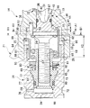
第1実施形態のディスクブレーキは、図1に示すように、車両の非回転部に固定されるキャリア11と、このキャリア11にディスク12を介して両側に配設された状態で摺動可能に支持される一対のパッド13と、キャリア11にディスク12の軸線方向に沿って摺動自在となるよう支持されて一対のパッド13を両側から挟持するキャリパ14とで主に構成されている。
As shown in FIG. 1, the disc brake of the first embodiment is slidable with a
キャリパ14は、一方のパッド13のディスク12に対し反対側に開口部17を対向させる有底筒状のシリンダ18と、このシリンダ18の半径方向における一側からディスク12の外周部を跨いで延出するディスクパス部19と、このディスクパス部19のシリンダ18に対し反対側から他方のパッド13のディスク12に対し反対側に対向するように延出する爪部20とを有するキャリパ本体21を有している。
The
また、キャリパ14は、有底筒状に形成されて底部24側をパッド13側に向けてキャリパ本体21のシリンダ18のボア25に摺動自在に嵌合されるピストン26と、ピストン26とシリンダ18の内周面28との隙間をシールするリング状のピストンシール27とを有している。なお、ピストンシール27はシリンダ18に保持されている。
The
キャリパ14は、シリンダ18とピストン26との間に導入されるブレーキ液圧によって、ピストン26をパッド13の方向に突出させることによって、このピストン26と爪部20とで一対のパッド13を両側から把持することによりディスク12に接触させるものである。
The
上記のように、ピストン26は、ブレーキペダルへの踏み込み操作による通常制動時には、図示せぬマスタシリンダからシリンダ18内に導入されるブレーキ液圧でシリンダ18から爪部20の方向に突出させられることにより一対のパッド13をディスク12に押圧させて制動力を発生させるものであるが、シリンダ18内には、ピストン26をこのようなブレーキ液圧ではなく機械的に突出させることにより一対のパッド13をディスク12に押圧させて制動力を発生させるパーキングブレーキ機構30が設けられている。
As described above, the
パーキングブレーキ機構30は、カム機構32を有している。
すなわち、シリンダ18の底部33には、底面34から離間してこのシリンダ18の軸線方向に対し直交方向にカム穴35が形成されており、また、底面34の中央位置からカム穴35まで軸線上において貫通する底部穴36が形成されていて、これらカム穴35および底部穴36にカム機構32が設けられている。
The
That is, a
このカム機構32は、カム穴35にベアリング38を介して回転可能に挿入された略円柱状のカム本体39を有している。カム本体39には、半径方向の外周面から中心方向に向けて略V字状に凹むカム凹部40が形成されている。このカム凹部40は、最も凹んだ位置をカム本体39の中心軸線に対しオフセットさせている。
The
カム機構32は、カム凹部40に一端側が挿入されるとともに他端側が底部穴36側に配置されるカムロッド42を有しており、このカムロッド42は、シリンダ18の軸線に直交する方向に沿う軸線回りにカム本体39が回転駆動されるとカム凹部40の形状によってカム本体39からの突出量を変化させる。なお、カム本体39は、図示せぬパーキングブレーキレバーの手動操作等により回転する。
The
また、シリンダ18内には、カム機構32のカムロッド42で押圧されてシリンダ18の軸線方向に移動するプッシュロッド44が設けられている。
A
そして、本実施形態においては、図2に示すように、プッシュロッド44が、前進時前側すなわちピストン26側の前部分割体45と、前進時後側すなわちシリンダ底部33側の後部分割体46とに二分割されている。
In this embodiment, as shown in FIG. 2, the
プッシュロッド44の後部分割体46は、軸部48とこの軸部48の一端側から半径方向外方に広がるフランジ部49とを有しており、図3に示すように、フランジ部49には半径方向外側に一部突出する複数具体的には二カ所の凸部50が180度異なる位置に形成されている。また、図2に示すように、軸線方向における軸部48のフランジ部49に対し反対側には軸線方向に凹む当接凹部51が形成されている。
The rear divided
なお、フランジ部49には凸部50の内側位置に軸線方向に貫通する嵌合穴52が形成されており、これら嵌合穴52には、それぞれガイドピン53が、軸線方向における両側が所定量ずつフランジ部49から突出する状態に圧入されている。加えて、フランジ部49には、凸部50と異なる位置に、外周面から一段凹む複数具体的には四カ所の回止凹部54が形成されている。
The
この後部分割体46は、図1に示すように、その軸部48がシリンダ18の底部穴36に摺動可能に嵌合させられることになる。ここで、シリンダ18の底部33には、中心から位置をずらして軸線方向に沿う回止穴56が複数具体的には二カ所底面34側から形成されており、軸部48が底部穴36に嵌合させられる際に、両ガイドピン53の軸部48側の部分がこれらの回止穴56に摺動可能に嵌合されることになる。
As shown in FIG. 1, the rear divided
なお、ガイドピン53と回止穴56との嵌合によって後部分割体46は、シリンダ18に対し軸回りの回転が規制された状態で軸方向に移動可能となる。
The rear divided
そして、後部分割体46は、上記のように軸部48が底部穴36に嵌合させられるとともに、ガイドピン53が回止穴56に嵌合させられた状態で、当接凹部51に上記カム機構32のカムロッド42の先端側を収納する。なお、軸部48とシリンダ18の底部穴36との間には、これらの隙間をシールするリング状のプッシュロッドシール57が設けられている。このプッシュロッドシール57は、後部分割体46の軸部48に保持されている。
The rear divided
プッシュロッド44の前部分割体45は、半径方向における外周面にオネジ60が形成された軸部61とこの軸部61の一端側から半径方向外方に広がるフランジ部62とを有する形状をなしており、フランジ部62の外周側には、図4に示すように、外周面から半径方向内方に円弧状に凹む複数具体的には二カ所の回止凹部63が形成されている。
The front divided
この前部分割体45は、図2に示すように、フランジ部62を後部分割体46のフランジ部49に対し当接させることになり、このときに、回止凹部63にガイドピン53の軸部48に対し反対側の部分を嵌合させることになる。なお、ガイドピン53と回止凹部63との嵌合によって前部分割体45は、後部分割体46に対し軸回りの回転が規制された状態で軸方向移動可能(つまり離間および近接可能)となる。
As shown in FIG. 2, the front divided
パーキングブレーキ機構30は、シリンダ18内においてプッシュロッド44の前部分割体45の軸部61のオネジ60に、内径側に形成されたメネジ65で螺合される略円筒状のクラッチ部材66を有している。
The
ここで、ピストン26の内径側は、底部24側が小径の小径内径部68とされるとともに、小径内径部68よりも開口側がこれより大径の大径内径部69とされており、これら小径内径部68および大径内径部69の間には大径内径部69側が大径となるように傾斜するテーパ面部70が形成されている。
Here, as for the inner diameter side of the
クラッチ部材66は、先端側がピストン26の小径内径部68に嵌合する嵌合部72とされており、この嵌合部72と隣り合ってテーパ面部70に当接するテーパ部73が形成されている。
The
ここで、カム機構32のカム本体39を回転運動させることにより、カムロッド42の突出量を小から大へ変化させると、プッシュロッド44の後部分割体46および前部分割体45とクラッチ部材66とが軸線方向に直線運動し、クラッチ部材66がテーパ部73においてピストン26のテーパ面部70に当接してこのピストン26をシリンダ18に対しパッド13側に摺動させる。
Here, when the amount of protrusion of the
なお、プッシュロッド44の前部分割体45のオネジ60とクラッチ部材66のメネジ65とは、螺合部74を構成しており、この螺合部74には、前部分割体45とクラッチ部材66との間に互いに回転せずに所定量軸方向に移動可能なクリアランスを有している。
The
また、ピストン26の底部24側にはクラッチ部材66との隙間を大気開放させるための大気開放穴76が形成されている。
In addition, an
加えて、クラッチ部材66の嵌合部72とピストン26の小径内径部68との間には、これらの隙間をシールするリング状のクラッチ部材シール77が設けられている。このクラッチ部材シール77は、クラッチ部材66の嵌合部72に保持されている。
In addition, a ring-shaped
パーキングブレーキ機構30は、シリンダ18内においてクラッチ部材66とプッシュロッド44の前部分割体45との位置調整を行うアジャスト部80を有している。
The
このアジャスト部80は、ピストン26の大径内径部69に形成された係合溝81に係合される止め輪82によってピストン26とクラッチ部材66との間に支持されるもので、ピストン26がシリンダ18内に導入されたブレーキ液圧によって軸方向に移動する際には、実質的には停止状態にあるプッシュロッド44に対し、クラッチ部材66を回転させながらピストン26に追従させて軸方向に移動させる。
The adjusting
また、アジャスト部80は、プッシュロッド44の前部分割体45が軸線方向に直線運動する際には、クラッチ部材66を前部分割体45に対し回転させることがなく、その結果、オネジ60とメネジ65とからなる螺合部74によってクラッチ部材66をプッシュロッド44と一体に直線運動させる。
In addition, the adjusting
パーキングブレーキ機構30は、シリンダ18内において、クラッチ部材66の一部とプッシュロッド44の前部分割体45および後部分割体46の一部とを覆うように設けられたスプリングカバー84と、プッシュロッド44の前部分割体45のフランジ部62とスプリングカバー84のピストン26側との間に介装されたプッシュロッド付勢スプリング(プッシュロッド付勢部材)85とを有している。
In the
スプリングカバー84は、内側にクラッチ部材66を挿入させるリング状部87と、このリング状部87の外径側から軸線方向一側に延出する円筒状部88と、円筒状部88のリング状部87に対し反対側から半径方向外側に切り起こされた複数の係止片部89と、円筒状部88のリング状部87に対し反対側からさらに軸線方向一側に延出する複数具体的には四カ所の延出片部90とを有している。
The
そして、スプリングカバー84は、各延出片部90が、図4に示すようにプッシュロッド44の前部分割体45のフランジ部62の外周面の外側を通り、図3に示すように後部分割体46のフランジ部49の各回止凹部54に係合して、さらにこのフランジ部49から突出する部分が、図2に示すように、半径方向内方に折り曲げられることになり、この折り曲げ後の折曲部91で後部分割体46のフランジ部49の軸部48側に係止される。
In the
この状態で、プッシュロッド付勢スプリング85は、スプリングカバー84のリング状部87とプッシュロッド44の前部分割体45のフランジ部62との間に介装されることになり、言い換えれば、スプリングカバー84は、プッシュロッド付勢スプリング85をプッシュロッド44の前部分割体45との間で保持することになる。
In this state, the push
ここで、スプリングカバー84は、その延出片部90を後部分割体46のフランジ部49の回止凹部54に係合させることで、この後部分割体46に対し軸線回りの回転が規制される。つまり、スプリングカバー84と、ガイドピン53で互いに回り止めされた前部分割体45、後部分割体46およびシリンダ18とが、相対的な回転が規制されることになる。
Here, the
なお、スプリングカバー84の折曲部91の折り曲げ位置は、カートリッジ93に一体化されたときのプッシュロッド付勢スプリング85の設定長が自由長X0よりも短い長さX1(X1は図2に示すX2とX3とを加算した長さ)となるように設定されている。さらに、カートリッジ93をシリンダ18の係合溝97へ挿通してカムロッド42を後部分割体46の当接凹部51に当接させてC字状止め輪98で係止した状態において、折曲部91はシリンダ18の底面34と当接しないようになっている。また、カムロッド42の当接によって、プッシュロッド付勢スプリング85は、さらに撓み、その長さは図2に示すような設定長X2となるとともに、フランジ部49と折曲部91との間にクリアランスX3が生じるようになっている。このように構成することにより、プッシュロッド44の位置決めがなされるとともに、プッシュロッド付勢スプリング85は、図5に示すように、前部分割体45を後部分割体46から所定のクリアランス99の分、離間させることができるように設定されている。
The bending position of the
そして、パーキングブレーキ機構30は、シリンダ18に組み付けられる前段階で、プッシュロッド44の前部分割体45と、ガイドピン53が予め設けられた状態にあるプッシュロッド44の後部分割体46と、プッシュロッド付勢スプリング85と、スプリングカバー84とが一つの組立体のカートリッジ93とされている。
The
すなわち、例えば、折曲部91が形成される前の状態のスプリングカバー84のリング状部87に当接するようにプッシュロッド付勢スプリング85を挿入し、プッシュロッド44の前部分割体45を、その軸部61側をプッシュロッド付勢スプリング85の内側に挿入してフランジ部62を延出片部90の内側に通しつつプッシュロッド付勢スプリング85に当接させる。
That is, for example, the push
そして、プッシュロッド44の後部分割体46を、そのフランジ部49の回止凹部54にスプリングカバー84の延出片部90を嵌合させ、かつそのガイドピン53を前部分割体45の回止凹部63に嵌合させるようにして、前部分割体45に当接させる。
Then, the rear divided
次に、前部分割体45と後部分割体46とが互いに所定距離離間可能となるようにクリアランスを設けつつ、スプリングカバー84のすべての延出片部90の先端部を後部分割体46のフランジ部49の前部分割体45に対し反対側において半径方向内方に折り曲げて折曲部91を形成して、後部分割体46のスプリングカバー84からの抜けを規制する。
Next, while providing a clearance so that the front divided
以上により、プッシュロッド44の前部分割体45および後部分割体46(ガイドピン53を含む)、プッシュロッド付勢スプリング85およびスプリングカバー84が一つの組立体のカートリッジ93となる。なお、プッシュロッドシール57については、カートリッジ93の組み立て前および組み立て後のいずれに取り付けても良い。
As described above, the front divided
シリンダ18内には、プッシュロッド44のプッシュロッド付勢スプリング85との当接面94よりもシリンダ18の開口部17側となる位置に係止段部96が形成されている。この係止段部96は、シリンダ18の内周面28に形成された環状の係合溝97と、この係合溝97に係合するC字状の止め輪98とで構成されている。
A locking
以上のディスクブレーキを組み立てる場合には、キャリパ本体21のカム穴35にベアリング38およびカム本体39を挿入し、カム凹部40を底部穴36側に向け、この状態で、カムロッド42をキャリパ本体21のシリンダ18に開口部17側から挿入しさらに底部穴36を介してカム凹部40に挿入する。
When assembling the above disc brake, the
次に、上記のように予め組み立てられたカートリッジ93を、プッシュロッドシール57を付けた状態で開口部17側からシリンダ18内に挿入し、そのプッシュロッド44の後部分割体46の軸部48を底部33の底部穴36に嵌合させつつこの軸部48の当接凹部51にカムロッド42を挿入させ、さらに、そのガイドピン53を回止穴56に嵌合させて、最終的に底面34に折曲部91において当接させる。なお、折曲部91が底面34に当接した状態で、後部分割体46のフランジ部49は底面34との間に隙間を有している。
Next, the
そして、シリンダ18内にC字状の止め輪98を挿入し、この止め輪98をシリンダ18の係合溝97に係合させる。すると、止め輪98がカートリッジ93のスプリングカバー84の係止片部89を係止して、カートリッジ93の抜けを規制する。
Then, a C-shaped
一方で、クラッチ部材シール77が装着されたクラッチ部材66をピストン26に嵌合させるとともに、アジャスト部80を止め輪82でピストン26に係止させることで、ピストン26、クラッチ部材66およびアジャスト部80を別の組立体としておき、この組立体を、シリンダ18に嵌合させつつそのクラッチ部材66をプッシュロッド44に螺合させることで、キャリパ14が組み立てられる。
On the other hand, the
このような構成のディスクブレーキでは、図示せぬパーキングブレーキレバーが操作されることによりカム機構32のカム本体39が回動させられると、カム機構32のカムロッド42が突出量を増やし、プッシュロッド44の後部分割体46をディスク12の方向に移動させる。すると、後部分割体46に当接する前部分割体45がディスク12の方向に移動し、これと一体にクラッチ部材66が移動して、ピストン26をディスク12の方向に移動させて、機械的に一対のパッド13をディスク12に押し付ける。
In the disc brake having such a configuration, when the cam
他方、通常のブレーキペダルによるブレーキ操作でブレーキ液圧がシリンダ18とピストン26との間に導入されると、ピストン26にはピストンシール27による受圧面積に対し液圧が作用してディスク12の方向への推進力が発生することになるが、クラッチ部材66にもクラッチ部材シール77による受圧面積に対し液圧が作用してディスク12の方向への推進力が発生し、初期においてはプッシュロッド44の前部分割体45との螺合部74における螺合のクリアランス分回転せずに軸線方向に移動してピストン26を押すことになる。
そして、さらにブレーキ液圧がシリンダ18内に導入されて、所定液圧以上になると、クラッチ部材66へ作用する液圧でクラッチ部材66がピストン26に押し付けられることになり、ピストン26に液圧が作用してディスク12の方向への推進力が発生することになり、クラッチ部材66にも液圧が作用してディスク12の方向への推進力が発生することになる。
On the other hand, when the brake fluid pressure is introduced between the
When the brake fluid pressure is further introduced into the
このとき、一方で、プッシュロッド44の後部分割体46にも、プッシュロッドシール57による受圧面積に対し液圧が作用して、ディスク12に対し反対方向への推進力が発生することになるが、プッシュロッド44が、上記のように前部分割体45と後部分割体46とに二分割されていることから、後部分割体46のディスク12に対し反対方向の推進力を、前部分割体45に生じるディスク12の方向への推進力から分離できる。
At this time, on the other hand, hydraulic pressure also acts on the rear divided
以上により、第1実施形態のディスクブレーキにおいては、高液圧時のピストン出力の損失を防止することができる。その結果、ピストン径の増大を抑制できてディスクブレーキの小型化を図ることができる。 As described above, in the disc brake of the first embodiment, it is possible to prevent loss of piston output at the time of high hydraulic pressure. As a result, an increase in piston diameter can be suppressed and the disc brake can be reduced in size.
また、プッシュロッド44は、ガイドピン53とスプリングカバー84とによってシリンダ18に対する回転が規制された状態で前部分割体45と後部分割体46とが軸方向にのみ近接および離間可能となっているため、このような回転を規制しつつ近接および離間可能にするためにスプライン結合を採用する場合に生じる、フレッティング摩耗でスプラインの歯が薄くなって制動時に異音を生じるようになる等の問題は生じない。
Further, in the
さらに、プッシュロッド44を前部分割体45と後部分割体46とに分割することで、そのままでは、例えばキャリパ本体21に対して後部分割体46を挿入した後に、さらにキャリパ本体21に対し前部分割体45を後部分割体46に対する位相を合わせながら当接するように挿入するという非常に煩雑な作業が必要となってしまうことになるが、これら前部分割体45および後部分割体46をキャリパ本体21の外で、互いの位相を合わせつつ当接させスプリングカバー84およびプッシュロッド付勢スプリング85と合わせて一つの組立体のカートリッジ93とすることで、上記した煩雑な作業が不要となる。したがって、組立工数の増大を抑制することができる。
Furthermore, by dividing the
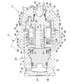
次に、本発明の第2実施形態のディスクブレーキを図6を参照して第1実施形態との相違部分を中心に以下に説明する。なお、第1実施形態と同様の部分は同一の符号を付しその説明を略す。 Next, a disc brake according to a second embodiment of the present invention will be described below with reference to FIG. 6, focusing on the differences from the first embodiment. In addition, the same code | symbol is attached | subjected to the part similar to 1st Embodiment, and the description is abbreviate | omitted.
第2実施形態においては、プッシュロッド44の前部分割体45とクラッチ部材66との螺合関係が第1実施形態とは逆になっている。すなわち、第2実施形態の前部分割体45は、軸部61に貫通孔100が形成されるとともに、この貫通孔100の内周面にメネジ101が形成されている。他方、第2実施形態のクラッチ部材66は、嵌合部72に対し反対側に軸部103が形成されており、この軸部103の外周面にオネジ104が形成されていて、これらメネジ101およびオネジ104が螺合して螺合部105を構成している。なお、この螺合部105にも、軸方向に所定のクリアランスが設けられている。
In the second embodiment, the screwing relationship between the front divided
以上に述べた第2実施形態においても、第1実施形態と同様の効果を奏することができる。 Also in the second embodiment described above, the same effects as in the first embodiment can be obtained.
次に、本発明の第3実施形態のディスクブレーキを図7を参照して第1実施形態との相違部分を中心に以下に説明する。なお、第1実施形態と同様の部分は同一の符号を付しその説明を略す。 Next, a disc brake according to a third embodiment of the present invention will be described below with reference to FIG. 7, focusing on the differences from the first embodiment. In addition, the same code | symbol is attached | subjected to the part similar to 1st Embodiment, and the description is abbreviate | omitted.
第3実施形態においては、後部分割体46のフランジ部49の嵌合穴52に嵌合するガイドピン53が回止穴56側にのみ突出し、しかも嵌合穴52の前部分割体45側の一部を残存させるように途中位置まで圧入されている。また、前部分割体45のフランジ部62の外径側には、軸部61に対し反対方向に突出する
ガイド突起部107が形成されている。
In the third embodiment, the
このような第3実施形態では、ガイドピン53が回止穴56に嵌合されることで、シリンダ18に対する回転が規制された後部分割体46の嵌合穴52に、前部分割体45のガイド突起部107が軸方向に摺動可能に嵌合することになり、これにより、前部分割体46と後部分割体46とが、相対回転が規制された状態で軸線方向に近接および離間可能となっている。そして、第1実施形態と同様、後部分割体46の回止凹部54に延出片部90を嵌合させることで、スプリングカバー84、前部分割体45、後部分割体46およびシリンダ18が、相対的な回転が規制されることになる。
In the third embodiment, the
この第3実施形態においても、第1実施形態とほぼ同様に、プッシュロッド44の前部分割体45および後部分割体46(ガイドピン53を含む)、プッシュロッド付勢スプリング85およびスプリングカバー84が一つの組立体のカートリッジ93とされることになるが、その組み立て時に、プッシュロッド44の後部分割体46を、前部分割体45に当接させる際に、フランジ部62のガイド突起部107を、フランジ部49の嵌合穴52に嵌合させることになる。以後は第1実施形態と同様である。
Also in the third embodiment, the front divided
以上に述べた第3実施形態においても、第1実施形態と同様の効果を奏することができる。 Also in the third embodiment described above, the same effects as in the first embodiment can be obtained.
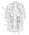
次に、本発明の第4実施形態のディスクブレーキを図8〜図10を参照して第1実施形態との相違部分を中心に以下に説明する。なお、第1実施形態と同様の部分は同一の符号を付しその説明を略す。 Next, a disc brake according to a fourth embodiment of the present invention will be described below with reference to FIGS. 8 to 10 focusing on differences from the first embodiment. In addition, the same code | symbol is attached | subjected to the part similar to 1st Embodiment, and the description is abbreviate | omitted.
第4実施形態においては、後部分割体46のフランジ部49の嵌合穴52は、貫通せず回止穴56側のみに形成されており、その結果、この嵌合穴52に嵌合するガイドピン53が回止穴56側にのみ突出している。また、図10に示すように、前部分割体45のフランジ部62の外径側には、半径方向外方に同軸状に突出する凸部108が複数具体的には四カ所形成されており、これら凸部108の外径側には、スプリングカバー84の延出片部90を嵌合させる回止凹部109がそれぞれ形成されている。
In the fourth embodiment, the
このような第4実施形態では、ガイドピン53が回止穴56に嵌合されることで、シリンダ18に対する回転が規制された後部分割体46に対し、第1実施形態と同様に回止凹部54に延出片部90を嵌合させることでスプリングカバー84の回転が規制されることになり、このスプリングカバー84の延出片部90を回止凹部109に嵌合させることで前部分割体45の回転が規制される。また、回止凹部109が延出片部90に沿って移動することで、前部分割体46と後部分割体46とが、相対回転が規制された状態で軸線方向に近接および離間可能となっている。
In the fourth embodiment, the
この第4実施形態においても、第1実施形態とほぼ同様に、プッシュロッド44の前部分割体45および後部分割体46(ガイドピン53を含む)、プッシュロッド付勢スプリング85およびスプリングカバー84が一つの組立体のカートリッジ93とされることになるが、その組み立て時において、プッシュロッド付勢スプリング85が当接させられた状態のスプリングカバー84に、プッシュロッド44の前部分割体45を挿入する際に、そのフランジ部62の回止凹部109を延出片部90に嵌合させる。そして、プッシュロッド44の後部分割体46を、そのフランジ部49の回止凹部54にスプリングカバー84の延出片部90を嵌合させるようにして、前部分割体45に当接させることになる。以後は、第1実施形態と同様である。
In the fourth embodiment, the front divided
以上に述べた第4実施形態においても、第1実施形態と同様の効果を奏することができる。 Also in the fourth embodiment described above, the same effects as in the first embodiment can be obtained.
次に、本発明の第5実施形態のディスクブレーキを図11および図12を参照して第1実施形態との相違部分を中心に以下に説明する。なお、第1実施形態と同様の部分は同一の符号を付しその説明を略す。 Next, a disc brake according to a fifth embodiment of the present invention will be described below with reference to FIGS. 11 and 12 focusing on differences from the first embodiment. In addition, the same code | symbol is attached | subjected to the part similar to 1st Embodiment, and the description is abbreviate | omitted.
第5実施形態においては、後部分割体46のフランジ部49には嵌合穴52は形成されておらず、よってガイドピン53も設けられていない。また、前部分割体45のフランジ部62の外径側には、図12に示すように、軸直交断面が半円状をなして半径方向外方に突出する回止凸部110が複数具体的には二カ所形成されており、またこれら回止凸部110に対し位置を異ならせて、スプリングカバー84の延出片部90を嵌合させる回止凹部111が形成されている。
さらに、シリンダ18の内周面28には、回止凸部110を嵌合させる軸直交断面が半円状の回止凹部112がそれぞれ形成されている。そして、回止凸部110と回止凹部112とは、前部分割体45のフランジ部62が回転したときに回止凸部110と回止凹部112との曲面同士が当接するようになっている。これは、回止凸部110が回止凹部112の端部の角部に当接した場合には、回止凸部110が磨耗してしまい、経年的に前部分割体45の回転を防止することができなくなる可能性があるが、回止凸部110と回止凹部112との曲面同士が当接するようになっていることにより、回止凸部110と回止凹部112とのいずれかが磨耗してしまっても、当接面が拡大することになり、経年的に、より強固に前部分割体45回転を防止することが可能となっている。
In 5th Embodiment, the
Further, the inner
このような第5実施形態では、シリンダ18の回止凹部112に前部分割体45の回止凸部110を嵌合させることで、これらの相対回転が規制され、スプリングカバー84の延出片部90を回止凹部111に嵌合させることで前部分割体45に対するスプリングカバー84の回転が規制され、さらに、このスプリングカバー84の延出片部90に回止凹部54を嵌合させることで、スプリングカバー84に対する後部分割体46の回転が規制される。また、回止凸部110が回止凹部112に沿いかつ回止凹部111が延出片部90に沿って移動することで、前部分割体46と後部分割体46とが、相対回転が規制された状態で軸線方向に近接および離間可能となっている。
In the fifth embodiment, the relative rotation is restricted by fitting the rotation
この第5実施形態においても、第1実施形態とほぼ同様に、プッシュロッド44の前部分割体45および後部分割体46、プッシュロッド付勢スプリング85およびスプリングカバー84が一つの組立体のカートリッジ93とされることになるが、その組み立て時において、プッシュロッド付勢スプリング85が当接させられた状態のスプリングカバー84に、プッシュロッド44の前部分割体45を挿入する際に、そのフランジ部62の回止凹部111を延出片部90に嵌合させる。そして、プッシュロッド44の後部分割体46を、そのフランジ部49の回止凹部54にスプリングカバー84の延出片部90を嵌合させるようにして、前部分割体45に当接させることになる。以後は、第1実施形態と同様である。そして、組み上がったカートリッジ93をシリンダ18に挿入する際に、回止凸部110を回止凹部112に嵌合させる。
Also in the fifth embodiment, substantially in the same manner as in the first embodiment, the front divided
以上に述べた第5実施形態においても、第1実施形態と同様の効果を奏することができる。また、回止凸部110と回止凹部112との曲面同士が当接するようになっているため、回止凸部110若しくは回止凹部112が磨耗した際にも、確実に前部分割体45の回転を防止することができる。
Also in the fifth embodiment described above, the same effects as in the first embodiment can be obtained. Further, since the curved surfaces of the anti-rotation
次に、本発明の第6実施形態のディスクブレーキを図13を参照して第1実施形態との相違部分を中心に以下に説明する。なお、第1実施形態と同様の部分は同一の符号を付しその説明を略す。 Next, a disc brake according to a sixth embodiment of the present invention will be described below with reference to FIG. 13 focusing on the differences from the first embodiment. In addition, the same code | symbol is attached | subjected to the part similar to 1st Embodiment, and the description is abbreviate | omitted.
第6実施形態においては、シリンダ18の内周面28の底面34側に、底面34から離れるほど大径となるテーパ面114が形成されている。このテーパ面114は、底面34側の端部の位置が後部分割体46のフランジ部49の軸方向における中間位置よりも底面34側とされている。また、後部分割体46のフランジ部49は底面34との間に常にクリアランス116を有している。
In the sixth embodiment, a
以上に述べた第6実施形態においては、第1実施形態と同様の効果を奏することができる上、テーパ面114がシリンダ18と後部分割体46のフランジ部49の外径側との間に隙間を形成することから、シリンダ18とピストン26との間にブレーキ液を導入する際にシリンダ18の底面34側に溜まるエアをこのテーパ面114で形成されたシリンダ18とフランジ部49との隙間を介して良好に抜くことができる。
In the sixth embodiment described above, the same effect as that of the first embodiment can be obtained, and the
次に、本発明の第7実施形態のディスクブレーキを図14を参照して第1実施形態との相違部分を中心に以下に説明する。なお、第1実施形態と同様の部分は同一の符号を付しその説明を略す。 Next, a disc brake according to a seventh embodiment of the present invention will be described below with reference to FIG. 14 focusing on the differences from the first embodiment. In addition, the same code | symbol is attached | subjected to the part similar to 1st Embodiment, and the description is abbreviate | omitted.
第7実施形態においては、シリンダ18の内周面28の上部かつ底面34側に、内周面28から一段凹むエア抜き溝115が形成されている。このエア抜き溝115は、底面34側の端部の位置が後部分割体46のフランジ部49の軸方向における中間位置よりも底面34側とされている。また、後部分割体46のフランジ部49は底面34との間に常にクリアランスを有している。なお、エア抜き溝115は、キャリパ本体21の鋳造時に形成されており、その結果、表面は鋳肌とされている。
In the seventh embodiment, an
以上に述べた第7実施形態においては、第1実施形態と同様の効果を奏することができる上、エア抜き溝115がシリンダ18と後部分割体46のフランジ部49の外径側との間に隙間を形成することから、シリンダ18とピストン26との間にブレーキ液を導入する際にシリンダ18の底面34側に溜まるエアをこのエア抜き溝115で形成されたシリンダ18とフランジ部49との隙間を介して良好に抜くことができる。
In the seventh embodiment described above, the same effects as in the first embodiment can be obtained, and the
12 ディスク
13 パッド
14 キャリパ
18 シリンダ
26 ピストン
32 カム機構
42 カムロッド
44 プッシュロッド
45 前部分割体
46 後部分割体
66 クラッチ部材
84 スプリングカバー
85 プッシュロッド付勢スプリング(プッシュロッド付勢部材)
93 カートリッジ
12
93 cartridges
Claims (4)
ピストンを有底筒状のシリンダに摺動可能に嵌合させるとともに前記ピストンの摺動によって前記一対のパッドを前記ディスクに接触させるキャリパと、
回転駆動されることでカムロッドの突出量を変化させるカム機構と、
前記シリンダ内に回転を規制されて配置され、前記カム機構の前記カムロッドで押圧されて移動するプッシュロッドと、
前記シリンダ内に配置され、前記プッシュロッドに螺合されてこれに対し回転可能とされるとともに前記ピストンにその間の隙間をシールされて嵌合する嵌合部および前記ピストンに当接、離間するテーパ部を有し、前記プッシュロッドで押圧されて前記ピストンを前記シリンダに対し強制的に摺動させるクラッチ部材と、
前記シリンダ内に配置され、前記プッシュロッドを前記カム機構の方向に付勢するプッシュロッド付勢部材と、
前記シリンダ内に配置され、前記プッシュロッド付勢部材を前記プッシュロッドとの間で保持するスプリングカバーと、を備えたディスクブレーキにおいて、
前記プッシュロッドと、前記プッシュロッド付勢部材と、前記スプリングカバーとを一つの組立体のカートリッジとし、前記プッシュロッドを、前記クラッチ部材に螺合される前部分割体と前記シリンダにその間の隙間をシールされて嵌合し前記カムロッドに係合される後部分割体とに二分割し、これら前部分割体および後部分割体は分割箇所に半径方向に広がるフランジ部をそれぞれ有し、前記スプリングカバーを前記後部分割体のフランジ部に係止することで前記前部分割体および前記後部分割体の分割面を前記カートリッジ内に内包し、前記前部分割体のフランジ部の外周側に形成される回り止め部により前記前部分割体は前記後部分割体の軸周りの回転が規制された状態で軸方向移動が可能とされたことを特徴とするディスクブレーキ。 A pair of pads arranged on both sides via a disc;
A caliper contacting the pair of pads to the disk by sliding of the piston causes the piston to a bottomed cylindrical cylinder slidably fitted,
A cam mechanism that changes the amount of protrusion of the cam rod by being driven to rotate;
A push rod which is arranged in the cylinder so that its rotation is restricted, and is moved by being pressed by the cam rod of the cam mechanism;
Wherein arranged in the cylinder, the push rod screwed by the fitting portion and abutting on the piston to be sealed therebetween clearance fit to be rotatable Rutotomoni the piston contrast, taper away part have a, a clutch member for being pressed forcibly sliding the piston relative to the cylinder by the push rod,
A push rod biasing member disposed in the cylinder and biasing the push rod toward the cam mechanism;
In a disc brake comprising: a spring cover disposed in the cylinder and holding the push rod biasing member between the push rod;
The push rod, the push rod biasing member, and the spring cover constitute a cartridge of one assembly, and the push rod is a gap between the front divided body screwed into the clutch member and the cylinder. The front cover and the rear split body each have a flange portion extending radially in the split portion, and the spring cover is fitted into the rear split body engaged with the cam rod. the dividing plane of the front split body and the rear split body by engaging the flange portion of the rear divided body is encapsulated in the cartridge, are formed on the outer peripheral side of the flange portion of said front split body It said front split body by detent portions disc brake, characterized in that the rotation about the axis of the rear divided body is possible axial movement while being regulated .
Priority Applications (1)
| Application Number | Priority Date | Filing Date | Title |
|---|---|---|---|
| JP2003333481A JP4275500B2 (en) | 2002-09-25 | 2003-09-25 | Disc brake |
Applications Claiming Priority (2)
| Application Number | Priority Date | Filing Date | Title |
|---|---|---|---|
| JP2002279455 | 2002-09-25 | ||
| JP2003333481A JP4275500B2 (en) | 2002-09-25 | 2003-09-25 | Disc brake |
Related Child Applications (1)
| Application Number | Title | Priority Date | Filing Date |
|---|---|---|---|
| JP2006236481A Division JP2006349189A (en) | 2002-09-25 | 2006-08-31 | Disc brake |
Publications (3)
| Publication Number | Publication Date |
|---|---|
| JP2004138240A JP2004138240A (en) | 2004-05-13 |
| JP2004138240A5 JP2004138240A5 (en) | 2006-08-10 |
| JP4275500B2 true JP4275500B2 (en) | 2009-06-10 |
Family
ID=32473099
Family Applications (1)
| Application Number | Title | Priority Date | Filing Date |
|---|---|---|---|
| JP2003333481A Expired - Fee Related JP4275500B2 (en) | 2002-09-25 | 2003-09-25 | Disc brake |
Country Status (1)
| Country | Link |
|---|---|
| JP (1) | JP4275500B2 (en) |
Families Citing this family (6)
| Publication number | Priority date | Publication date | Assignee | Title |
|---|---|---|---|---|
| JP2006038163A (en) * | 2004-07-29 | 2006-02-09 | Hitachi Ltd | Disc brake |
| JP4486029B2 (en) * | 2005-11-29 | 2010-06-23 | 曙ブレーキ工業株式会社 | Disc brake actuator with parking operation mechanism |
| KR101234624B1 (en) * | 2006-09-14 | 2013-02-19 | 기아자동차주식회사 | Integral caliper type brake parking system |
| JP5229492B2 (en) * | 2009-03-31 | 2013-07-03 | 日立オートモティブシステムズ株式会社 | Disc brake device |
| JP6076209B2 (en) * | 2013-06-25 | 2017-02-08 | 本田技研工業株式会社 | Saddle riding vehicle |
| CN103727154A (en) * | 2014-01-14 | 2014-04-16 | 安思通(厦门)制动系统有限公司 | Integrated parking braking device |
-
2003
- 2003-09-25 JP JP2003333481A patent/JP4275500B2/en not_active Expired - Fee Related
Also Published As
| Publication number | Publication date |
|---|---|
| JP2004138240A (en) | 2004-05-13 |
Similar Documents
| Publication | Publication Date | Title |
|---|---|---|
| US8733513B2 (en) | Disk brake | |
| US6811002B2 (en) | Disc brake | |
| JPH031534B2 (en) | ||
| JP5342966B2 (en) | Disc brake | |
| JP4275500B2 (en) | Disc brake | |
| JP4455528B2 (en) | Disc brake | |
| WO2018139306A1 (en) | Disk brake | |
| JP2006349189A (en) | Disc brake | |
| JP4194870B2 (en) | Disc brake | |
| JP4381335B2 (en) | Disc brake device and method for forming cylinder hole in disc brake device | |
| JP4130351B2 (en) | Disc brake | |
| KR20190002134A (en) | Break Apparatus | |
| JP4298562B2 (en) | Disc brake | |
| JP4194967B2 (en) | Disc brake | |
| KR20170010545A (en) | Disc Brake | |
| JP3774003B2 (en) | Disc brake | |
| JP3929757B2 (en) | Disc brake | |
| JP2549842Y2 (en) | Disc brake with parking brake mechanism | |
| JP2006038163A (en) | Disc brake | |
| JP7281566B2 (en) | disc brake | |
| JP2556636Y2 (en) | Disc brake with parking brake mechanism | |
| JP2556635Y2 (en) | Disc brake with parking brake mechanism | |
| JP2556638Y2 (en) | Disc brake with parking brake mechanism | |
| JP2556634Y2 (en) | Disc brake with parking brake mechanism | |
| JPH1193992A (en) | Disk brake device |
Legal Events
| Date | Code | Title | Description |
|---|---|---|---|
| A711 | Notification of change in applicant |
Free format text: JAPANESE INTERMEDIATE CODE: A712 Effective date: 20041129 |
|
| A521 | Request for written amendment filed |
Free format text: JAPANESE INTERMEDIATE CODE: A523 Effective date: 20060627 |
|
| A621 | Written request for application examination |
Free format text: JAPANESE INTERMEDIATE CODE: A621 Effective date: 20060627 |
|
| A977 | Report on retrieval |
Free format text: JAPANESE INTERMEDIATE CODE: A971007 Effective date: 20080804 |
|
| A131 | Notification of reasons for refusal |
Free format text: JAPANESE INTERMEDIATE CODE: A131 Effective date: 20080812 |
|
| A521 | Request for written amendment filed |
Free format text: JAPANESE INTERMEDIATE CODE: A523 Effective date: 20081014 |
|
| TRDD | Decision of grant or rejection written | ||
| A01 | Written decision to grant a patent or to grant a registration (utility model) |
Free format text: JAPANESE INTERMEDIATE CODE: A01 Effective date: 20090224 |
|
| A01 | Written decision to grant a patent or to grant a registration (utility model) |
Free format text: JAPANESE INTERMEDIATE CODE: A01 |
|
| A61 | First payment of annual fees (during grant procedure) |
Free format text: JAPANESE INTERMEDIATE CODE: A61 Effective date: 20090304 |
|
| R150 | Certificate of patent or registration of utility model |
Ref document number: 4275500 Country of ref document: JP Free format text: JAPANESE INTERMEDIATE CODE: R150 Free format text: JAPANESE INTERMEDIATE CODE: R150 |
|
| FPAY | Renewal fee payment (event date is renewal date of database) |
Free format text: PAYMENT UNTIL: 20120313 Year of fee payment: 3 |
|
| S111 | Request for change of ownership or part of ownership |
Free format text: JAPANESE INTERMEDIATE CODE: R313111 |
|
| FPAY | Renewal fee payment (event date is renewal date of database) |
Free format text: PAYMENT UNTIL: 20120313 Year of fee payment: 3 |
|
| R350 | Written notification of registration of transfer |
Free format text: JAPANESE INTERMEDIATE CODE: R350 |
|
| FPAY | Renewal fee payment (event date is renewal date of database) |
Free format text: PAYMENT UNTIL: 20130313 Year of fee payment: 4 |
|
| FPAY | Renewal fee payment (event date is renewal date of database) |
Free format text: PAYMENT UNTIL: 20130313 Year of fee payment: 4 |
|
| FPAY | Renewal fee payment (event date is renewal date of database) |
Free format text: PAYMENT UNTIL: 20140313 Year of fee payment: 5 |
|
| R250 | Receipt of annual fees |
Free format text: JAPANESE INTERMEDIATE CODE: R250 |
|
| S533 | Written request for registration of change of name |
Free format text: JAPANESE INTERMEDIATE CODE: R313533 |
|
| R350 | Written notification of registration of transfer |
Free format text: JAPANESE INTERMEDIATE CODE: R350 |
|
| R250 | Receipt of annual fees |
Free format text: JAPANESE INTERMEDIATE CODE: R250 |
|
| LAPS | Cancellation because of no payment of annual fees |