JP4298562B2 - Disc brake - Google Patents
Disc brake Download PDFInfo
- Publication number
- JP4298562B2 JP4298562B2 JP2004101688A JP2004101688A JP4298562B2 JP 4298562 B2 JP4298562 B2 JP 4298562B2 JP 2004101688 A JP2004101688 A JP 2004101688A JP 2004101688 A JP2004101688 A JP 2004101688A JP 4298562 B2 JP4298562 B2 JP 4298562B2
- Authority
- JP
- Japan
- Prior art keywords
- cylinder
- piston
- push rod
- end side
- divided body
- Prior art date
- Legal status (The legal status is an assumption and is not a legal conclusion. Google has not performed a legal analysis and makes no representation as to the accuracy of the status listed.)
- Expired - Lifetime
Links
- 238000000926 separation method Methods 0.000 abstract description 5
- 239000007788 liquid Substances 0.000 abstract 1
- 239000012530 fluid Substances 0.000 description 10
- 230000002093 peripheral effect Effects 0.000 description 9
- 230000001141 propulsive effect Effects 0.000 description 7
- 230000004048 modification Effects 0.000 description 5
- 238000012986 modification Methods 0.000 description 5
- 210000000078 claw Anatomy 0.000 description 3
- 230000002265 prevention Effects 0.000 description 2
- 238000005452 bending Methods 0.000 description 1
- 230000000881 depressing effect Effects 0.000 description 1
- 230000000149 penetrating effect Effects 0.000 description 1
- 238000007789 sealing Methods 0.000 description 1
Images


Landscapes
- Braking Arrangements (AREA)
Abstract
Description
本発明は、パーキングブレーキ兼用型のディスクブレーキに関する。 The present invention relates to a parking brake combined type disc brake.
従来、車両のディスクブレーキにおいては、ブレーキペダルの操作等に基づくマスタシリンダからの液圧により推進するピストンによってブレーキパッドをディスクロータに押圧して車両の制動を行うとともに、パーキングブレーキレバーの操作等によりワイヤ等を介して駆動される押圧機構によってピストンを推進してブレーキパッドをディスクロータに押圧して車両の停止状態を維持するパーキングブレーキ兼用型のディスクブレーキがある。 Conventionally, in a disc brake of a vehicle, a brake is pressed against a disc rotor by a piston propelled by a hydraulic pressure from a master cylinder based on an operation of a brake pedal, etc., and the vehicle is braked. There is a parking brake combined type disk brake that pushes a piston by a pressing mechanism driven through a wire or the like and presses a brake pad against a disk rotor to maintain a stopped state of the vehicle.
このようなパーキングブレーキ兼用型のディスクブレーキでは、押圧機構で押圧されるプッシュロッドと、このプッシュロッドに螺合されるとともにピストンに当接するクラッチ部材とを有する摩耗補償機構が設けられている。この摩耗補償機構により、ブレーキパッドの摩耗でピストンの初期位置が前進したときでも、所定ストロークでパーキングブレーキを作動させることができる。 Such a parking brake combined type disc brake is provided with a wear compensation mechanism having a push rod pressed by a pressing mechanism and a clutch member screwed into the push rod and abutting on the piston. With this wear compensation mechanism, the parking brake can be operated with a predetermined stroke even when the initial position of the piston advances due to wear of the brake pad.
このような摩耗補償機構は、通常の液圧による制動時に作動することになるが、摩耗補償作動後の液圧上昇により摩耗補償分以上にピストンの初期位置を前進させてしまう過調整を防止するために、プッシュロッドをピストンとともに推進させるようになっている(過調整防止作動)。このとき、プッシュロッドにはシリンダの底部の貫通穴との隙間をシールするOリングが設けられており、上記過調整防止作動時のプッシュロッドの推進時に、このOリングの受圧面積で推進方向とは反対方向にも液圧による力がかかってしまう。これにより、ピストンの出力効率に影響を及ぼしてしまうことがある。 Such a wear compensation mechanism operates at the time of braking by normal hydraulic pressure, but prevents excessive adjustment that advances the initial position of the piston beyond the amount of wear compensation due to an increase in hydraulic pressure after the wear compensation operation. Therefore, the push rod is propelled together with the piston (over-adjustment preventing operation). At this time, the push rod is provided with an O-ring that seals the gap with the through hole at the bottom of the cylinder. When the push rod is propelled during the over-adjustment preventing operation, the pressure receiving area of the O-ring The force by the hydraulic pressure is applied in the opposite direction. This may affect the output efficiency of the piston.
このため、プッシュロッドを軸方向において2分割して、上記Oリングの受圧面積に対しかかる液圧をピストンに作用させないようにしたものがある(例えば特許文献1参照)。
上記した特許文献1のものは、プッシュロッドの分割体同士の相対回転を防止する必要があるため、両分割体の分割面に凹凸を設けてこの凹凸をスプライン結合させたものとなっている。このような構造であると、凹部の底面と凸部の先端面とが密着状態となるため、凸部の先端面にはシリンダ内の液圧がかからず、過調整防止作動時の分割体同士の離れ始めが遅くなり、その分、ピストンの入力に対する出力効率が低下してしまうという問題があった。 Since the thing of above-mentioned patent document 1 needs to prevent the relative rotation of the split bodies of a push rod, the unevenness | corrugation was provided in the division surface of both the split bodies, and this unevenness | corrugation was spline-joined. With such a structure, the bottom surface of the concave portion and the tip surface of the convex portion are in close contact with each other, so that the hydraulic pressure in the cylinder is not applied to the tip surface of the convex portion, and the divided body at the time of overadjustment prevention operation There was a problem that the start of separation between the two became slow, and the output efficiency with respect to the input of the piston was reduced accordingly.
したがって、本発明は、過調整防止作動時の分割体同士の離れ始めを早くすることができ、ピストンの入力に対する出力効率を向上させることができるディスクブレーキの提供を目的とする。 Therefore, an object of the present invention is to provide a disc brake that can accelerate the start of separation between the divided bodies during the over-adjustment preventing operation and can improve the output efficiency with respect to the input of the piston.
上記目的を達成するため、請求項1の発明は、ディスクを介して両側に配置される一対のパッドと、ピストンを液圧が供給されるシリンダのボアに摺動可能に嵌合させるとともに前記ピストンの摺動によって前記一対のパッドをディスクに接触させるキャリパと、前記シリンダのボア外に配置され、前記ピストンの摺動方向に押圧力を発生する押圧機構と、前記シリンダ内に配置され、前記押圧機構で押圧される一端側分割体とオネジ部が形成される他端側分割体とに軸線方向において分割され、両分割体の分割面が平面で直接当接するプッシュロッドと、前記シリンダ内に配置され、前記プッシュロッドの前記他端側分割体に螺合されるとともに前記ピストンに当接し、前記プッシュロッドで押圧されて前記ピストンを押圧するクラッチ部材と、前記押圧機構と前記プッシュロッドの両分割体の分割面との間に設けられ、前記シリンダと前記一端側分割体との隙間をシールするプッシュロッドシールと、を備え、前記プッシュロッドの前記一端側分割体と前記他端側分割体との分割面には、前記シリンダ内に常時開口する空間部が設けられていることを特徴としている。
請求項2の発明は、前記空間部は、前記一端側分割体または前記他端側分割体の分割面に形成された溝であることを特徴としている。
請求項3の発明は、ディスクを介して両側に配置される一対のパッドと、ピストンを液圧が供給されるシリンダに摺動可能に嵌合させるとともに前記ピストンの摺動によって前記一対のパッドをディスクに接触させるキャリパと、前記シリンダのボア外に配置され、前記ピストンの摺動方向に押圧力を発生する押圧機構と、前記シリンダ内に配置され、前記押圧機構で押圧される一端側分割体とオネジ部が形成される他端側分割体とに軸線方向において分割されるプッシュロッドと、前記シリンダ内に配置され、前記プッシュロッドの前記他端側分割体に螺合されるとともに前記ピストンに当接し、前記プッシュロッドで押圧されて前記ピストンを押圧するクラッチ部材と、を備え、前記プッシュロッドの前記一端側分割体と前記他端側分割体との分割面には、前記シリンダ内に常時開口し、前記分割面の中心を通る直径位置において前記分割面を横断して互いに直交する二ヵ所の溝を設けることを特徴としている。
In order to achieve the above object, the invention according to claim 1 is characterized in that a pair of pads disposed on both sides via a disk and a piston are slidably fitted to a bore of a cylinder to which hydraulic pressure is supplied, and the piston A caliper that brings the pair of pads into contact with the disk by sliding, a pressing mechanism that is disposed outside the bore of the cylinder and generates a pressing force in the sliding direction of the piston, and is disposed within the cylinder, are divided in the axial direction and the other end side divided body whose one end divided body which is pressed by the mechanism and the male screw portion is formed, and the push rod divided surfaces of the two divided members is you contact directly with the plane, in the cylinder And a clutch portion that is screwed into the other end side divided body of the push rod, contacts the piston, and is pressed by the push rod to press the piston. When the pressing mechanism and provided between the divided surfaces of the two divided members of the push rod, e Bei and a push rod seal for sealing a gap between the one end divided body and said cylinder, said push rod wherein the divided surface of one side divided body and the other end divided body, is characterized in that space which always opens into the cylinder is provided.
The invention of claim 2 is characterized in that the space portion is a groove formed in a dividing surface of the one end side divided body or the other end side divided body.
According to a third aspect of the present invention, a pair of pads disposed on both sides via a disk and a piston are slidably fitted to a cylinder to which hydraulic pressure is supplied, and the pair of pads are slid by sliding of the piston. A caliper that comes into contact with the disk, a pressing mechanism that is arranged outside the bore of the cylinder and generates a pressing force in the sliding direction of the piston, and a one-end-side divided body that is arranged inside the cylinder and pressed by the pressing mechanism And a push rod that is divided in the axial direction into the other end side divided body in which the male thread portion is formed, and is disposed in the cylinder, screwed into the other end side divided body of the push rod, and to the piston A clutch member that abuts and is pressed by the push rod to press the piston, and the one end side split body and the other end side split of the push rod And the split surfaces, always open in the cylinder, is characterized in that across the dividing plane diametrically position passing through the center of the dividing plane provided two Kasho grooves orthogonal to each other.
本発明によれば、シリンダへの高液圧負荷時に、ピストンに液圧が作用してディスクの方向への推進力が発生することになり、クラッチ部材にも液圧が作用してディスクの方向への推進力が発生することになる一方、プッシュロッドには、クラッチ部材がピストンを押圧する方向とは逆方向に液圧が作用することになる。このとき、プッシュロッドが、押圧機構で押圧される一端側分割体とクラッチ部材に螺合する他端側分割体とに二分割されていることから、これらの分割面間にクリアランスが生じて、一端側分割体のディスクに対し反対方向の推進力を、他端側分割体に生じるディスクの方向への推進力から分離できる。そして、このとき、一端側分割体と他端側分割体との分割面に、シリンダ内に常時開口する空間部が設けられているため、シリンダへの高液圧負荷時に、一端側分割体と他端側分割体とが密着状態になってしまうのを防止できる。したがって、過調整防止作動時の分割体同士の離れ始めを早くすることができ、ピストンの入力に対する出力効率を向上させることができる。 According to the present invention, when a high hydraulic pressure is applied to the cylinder, the hydraulic pressure acts on the piston to generate a propulsive force in the direction of the disk, and the hydraulic pressure acts on the clutch member and the direction of the disk. On the other hand, a hydraulic force acts on the push rod in the direction opposite to the direction in which the clutch member presses the piston. At this time, since the push rod is divided into the one end side divided body pressed by the pressing mechanism and the other end side divided body screwed into the clutch member, a clearance is generated between these divided surfaces, The propulsive force in the opposite direction to the disk of the one end side divided body can be separated from the propulsive force generated in the other end side divided body in the direction of the disk. And at this time, since the space part which always opens in a cylinder is provided in the splitting surface of the one end side split body and the other end side split body , the one end side split body and It can prevent that an other end side division body will be in close_contact | adherence state. Therefore, it is possible to speed up the start of separation between the divided bodies during the overadjustment prevention operation, and it is possible to improve the output efficiency with respect to the input of the piston.
本発明の一実施形態のディスクブレーキを図面を参照して以下に説明する。 A disc brake according to an embodiment of the present invention will be described below with reference to the drawings.
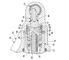
本実施形態のディスクブレーキは、図1に示すように、車両の非回転部に固定されるキャリア11と、このキャリア11にディスク12を介して両側に配設された状態で摺動可能に支持される一対のパッド13と、キャリア11にディスク12の軸線方向に沿って摺動自在となるよう支持されて一対のパッド13を両側から挟持するキャリパ14とで主に構成されている。
As shown in FIG. 1, the disc brake of the present embodiment is slidably supported with a
キャリパ14は、一方のパッド13のディスク12に対し反対側に開口部17を対向させる有底筒状のシリンダ18と、このシリンダ18の半径方向における一側からディスク12の外周部を跨いで延出するディスクパス部19と、このディスクパス部19のシリンダ18に対し反対側から他方のパッド13のディスク12に対し反対側に対向するように延出する爪部20とを有するキャリパ本体21を有している。
The
また、キャリパ14は、有底筒状に形成されて底部24側をパッド13側に向けてキャリパ本体21のシリンダ18のボア25の内周面に摺動自在に嵌合されるピストン26と、ピストン26とシリンダ18のボア25の内周面との隙間をシールするリング状のピストンシール27とを有している。なお、ピストンシール27はシリンダ18に保持されている。
The
キャリパ14は、シリンダ18とピストン26との間に導入されるブレーキ液圧によって、ピストン26をパッド13の方向に突出させることによって、このピストン26と爪部20とで一対のパッド13を両側から把持することによりディスク12に接触させるものである。
The
上記のように、ピストン26は、ブレーキペダルへの踏み込み操作による通常制動時には、図示せぬマスタシリンダからシリンダ18内に導入されるブレーキ液圧でシリンダ18から爪部20の方向に突出させられることにより一対のパッド13をディスク12に押圧させて制動力を発生させるものであるが、シリンダ18内には、ピストン26をこのようなブレーキ液圧ではなく機械的に突出させることにより一対のパッド13をディスク12に押圧させて制動力を発生させるパーキングブレーキ機構30が設けられている。
As described above, the
パーキングブレーキ機構30は、シリンダ18のボア25の外側に配置され、ピストン26の摺動方向に押圧力を発生するカム機構(押圧機構)32を有している。
The
すなわち、シリンダ18の底部33には、ボア25の底面34から離間してこのシリンダ18の軸線方向に対し直交方向にカム穴35が形成されており、また、底面34の中央位置からカム穴35まで軸線上において貫通する底部穴36が形成されていて、これらカム穴35および底部穴36にカム機構32が設けられている。
That is, a
このカム機構32は、カム穴35にベアリング38を介して回転可能に挿入された略円柱状のカム本体39を有している。カム本体39には、半径方向の外周面から中心方向に向けて略V字状に凹むカム凹部40が形成されている。このカム凹部40は、最も凹んだ位置をカム本体39の中心軸線に対しオフセットさせている。
The
カム機構32は、カム凹部40に一端側が挿入されるとともに他端側が底部穴36側に配置されるカムロッド42を有しており、このカムロッド42は、シリンダ18の軸線に直交する方向に沿う軸線回りにカム本体39が回転駆動されるとカム凹部40の形状によってカム本体39からの突出量を変化させる。なお、カム本体39は、図示せぬパーキングブレーキレバーの手動操作等により回転する。
The
また、シリンダ18内には、カム機構32のカムロッド42で押圧されてシリンダ18の軸線方向に移動するプッシュロッド44が設けられている。
A
本実施形態においては、プッシュロッド44が、前進時前側すなわちピストン26側の前部分割体(他端側分割体)45と、前進時後側すなわちシリンダ底部側の後部分割体(一端側分割体)46とに二分割されている。
In this embodiment, the
プッシュロッド44の後部分割体46は、カム機構32で押圧されるもので、軸部48とこの軸部48の一端側から半径方向外方に広がるフランジ部49とを有している。また、軸線方向における軸部48のフランジ部49に対し反対側には軸線方向に凹む当接凹部51が形成されており、フランジ部49の軸部48とは反対側の外周部には軸線方向に凹む環状の段部50が形成されている。
The rear divided
この後部分割体46は、その軸部48がシリンダ18の底部穴36に摺動可能に嵌合させられることになる。後部分割体46は、上記のように軸部48が底部穴36に嵌合させられた状態で当接凹部51に上記カム機構32のカムロッド42の先端側を収納する。なお、軸部48とシリンダ18の底部穴36との間には、これらの隙間をシールするリング状のプッシュロッドシール52が設けられている。このプッシュロッドシール52は、後部分割体46の軸部48に保持されている。
The rear divided
プッシュロッド44の前部分割体45は、半径方向における外周面にオネジ部53が形成された軸部54とこの軸部54の一端側から半径方向外方に広がるフランジ部55とを有する形状をなしており、フランジ部55を後部分割体46のフランジ部49に当接させることになる。このとき、前部分割体45のフランジ部55の軸部54とは反対側の面がプッシュロッド44を分割する分割面56となり、これに対向する後部分割体46のフランジ部49の軸部48とは反対側の面もプッシュロッド44を分割する分割面57となって、前部分割体45および後部分割体46はこれら分割面56,57で当接する。
The front divided
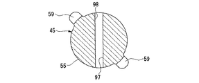
前部分割体45は、図2および図3に示すように、フランジ部55に半径方向外側に一部突出する複数具体的には二カ所の凸部59が180度異なる位置に形成されている。これら凸部59は、フランジ部55の軸線方向に直交する断面がフランジ部55の半径方向に凸状の略半円状をなしている。
As shown in FIGS. 2 and 3, the front divided
これに対して、シリンダ18の底部33側のボア25の内周面には、シリンダ18の軸線方向に延びる凹部60が互いに180度異なる位置に形成されている。これら凹部60は、延在方向に直交する断面がシリンダ18の半径方向に凹状の略半円状をなしている。
On the other hand, on the inner peripheral surface of the
そして、このシリンダ18の凹部60に、前部分割体45のフランジ部55の半径方向外側に突出する凸部59が摺動可能となるように嵌合させられる。この凸部59の凹部60への嵌合によって前部分割体45は、シリンダ18に対し軸回りの回転が規制された状態で軸方向に移動可能つまり後部分割体46に対し離間および近接可能となる。
And the
パーキングブレーキ機構30は、シリンダ18内においてプッシュロッド44の前部分割体45の軸部54のオネジ部53に、内径側に形成されたメネジ部65で螺合される略円筒状のクラッチ部材66を有している。
The
ここで、ピストン26の内径側は、底部24側が小径の小径内径部68とされるとともに、小径内径部68よりも開口側がこれより大径の大径内径部69とされており、これら小径内径部68および大径内径部69の間には大径内径部69側が大径となるように傾斜するテーパ面部70が形成されている。
Here, as for the inner diameter side of the
クラッチ部材66は、先端側がピストン26の小径内径部68に嵌合する嵌合部72とされており、この嵌合部72と隣り合ってテーパ面部70に当接するテーパ部73が形成されている。
The
ここで、カム機構32のカム本体39を回転運動させることにより、カムロッド42の突出量を小から大へ変化させると、プッシュロッド44の後部分割体46および前部分割体45とクラッチ部材66とが軸線方向に直線運動し、クラッチ部材66がテーパ部73においてピストン26のテーパ面部70に当接してこのピストン26をシリンダ18に対しパッド13側に摺動させる。
Here, when the amount of protrusion of the
なお、プッシュロッド44の前部分割体45のオネジ部53とクラッチ部材66のメネジ部65とは、螺合部74を構成しており、この螺合部74には、前部分割体45とクラッチ部材66との間に互いに回転せずに所定量軸方向に移動可能なクリアランスを有している。
The male threaded
また、ピストン26の底部24側にはクラッチ部材66との隙間を大気開放させるための大気開放穴76が形成されている。
In addition, an
加えて、クラッチ部材66の嵌合部72とピストン26の小径内径部68との間には、これらの隙間をシールするリング状のクラッチ部材シール77が設けられている。このクラッチ部材シール77は、クラッチ部材66の嵌合部72に保持されている。
In addition, a ring-shaped
パーキングブレーキ機構30は、シリンダ18内においてクラッチ部材66とプッシュロッド44の前部分割体45との位置調整を行うアジャスト部80を有している。
The
このアジャスト部80は、ピストン26の大径内径部69に形成された係合溝81に係合される止め輪82によってピストン26とクラッチ部材66との間に支持されるもので、ピストン26がシリンダ18内に導入されたブレーキ液圧によって軸方向に移動する際には、実質的には停止状態にあるプッシュロッド44に対し、クラッチ部材66を回転させながらピストン26に追従させて軸方向に移動させる。
The adjusting
また、アジャスト部80は、プッシュロッド44の前部分割体45が軸線方向に直線運動する際には、クラッチ部材66を前部分割体45に対し回転させることがなく、その結果、オネジ部53とメネジ部65とからなる螺合部74によってクラッチ部材66をプッシュロッド44と一体に直線運動させる。
In addition, the adjusting
パーキングブレーキ機構30は、シリンダ18内において、クラッチ部材66の一部とプッシュロッド44の前部分割体45および後部分割体46の一部とを覆うように設けられたスプリングカバー84と、プッシュロッド44の前部分割体45のフランジ部55とスプリングカバー84のピストン26側との間に介装されたプッシュロッド付勢スプリング(プッシュロッド付勢部材)85とを有している。
In the
スプリングカバー84は、内側にクラッチ部材66を挿入させるリング状部87と、このリング状部87の外径側から軸線方向一側に延出する円筒状部88と、円筒状部88のリング状部87に対し反対側から半径方向外側に切り起こされた複数の係止片部89と、円筒状部88のリング状部87に対し反対側からさらに軸線方向一側に延出する複数具体的には四カ所の延出片部90とを有している。
The
そして、スプリングカバー84は、各延出片部90が、プッシュロッド44の前部分割体45のフランジ部55の外周面の外側を通り、後部分割体46のフランジ部49の外周面の外側を通って、さらにこのフランジ部49から突出する部分が、半径方向内方に折り曲げられることになり、この折り曲げ後の折曲部91で後部分割体46のフランジ部49の軸部48側に係止される。
In the
この状態で、プッシュロッド付勢スプリング85は、スプリングカバー84のリング状部87とプッシュロッド44の前部分割体45のフランジ部55との間に介装されることになり、言い換えれば、スプリングカバー84は、プッシュロッド付勢スプリング85をプッシュロッド44の前部分割体45との間で保持することになる。
In this state, the push
上記したプッシュロッド44の前部分割体45と、プッシュロッド44の後部分割体46と、プッシュロッド付勢スプリング85と、スプリングカバー84とは、一つの組立体のカートリッジ93としてサブアセンブリ化され、その後、シリンダ18に組み付けられる。なお、カートリッジ93は、スプリングカバー84の係止片部89がシリンダ18の内周面に形成された嵌合溝94に嵌合される止め輪95で係止されることでシリンダ18から抜け止めされる。
The front divided
そして、本実施形態においては、図1および図2等に示すように、前部分割体45のフランジ部55の分割面56と後部分割体46のフランジ部49の分割面57との間に、シリンダ18内に常時開口する空間部97が設けられている。
In the present embodiment, as shown in FIGS. 1 and 2, etc., between the
この空間部97は、図3および図4にも示すように前部分割体45の分割面56に分割面56から凹むように溝98を形成することで設けられている。溝98は、分割面56の中心を通る直径位置において分割面56を横断しており、互いに直交するように二カ所形成されている。ここで、これらの溝98は凸部59が設けられた位置とは位相をずらして形成されている。これらの溝98は、延在方向に直交する断面が図4に示すようにV字状をなしている。
As shown in FIGS. 3 and 4, the
このような構成のディスクブレーキでは、図示せぬパーキングブレーキレバーが操作されることによりカム機構32のカム本体39が回動させられると、カム機構32のカムロッド42が突出量を増やし、プッシュロッド44の後部分割体46をディスク12の方向に移動させる。すると、後部分割体46に当接する前部分割体45がディスク12の方向に移動し、これと一体にクラッチ部材66が移動して、ピストン26をディスク12の方向に移動させて、機械的に一対のパッド13をディスク12に押し付ける。
In the disc brake having such a configuration, when the cam
他方、通常のブレーキペダルによるブレーキ操作でブレーキ液圧がシリンダ18とピストン26との間に導入されると、ピストン26にはピストンシール27による受圧面積に対し液圧が作用してディスク12の方向への推進力が発生することになるが、クラッチ部材66にもクラッチ部材シール77による受圧面積に対し液圧が作用してディスク12の方向への推進力が発生し、初期においてはプッシュロッド44の前部分割体45との螺合部74における螺合のクリアランス分回転せずに軸線方向に移動してピストン26を押すことになる。
On the other hand, when the brake fluid pressure is introduced between the
そして、さらにブレーキ液圧がシリンダ18内に導入されて、所定液圧以上になると、クラッチ部材66へ作用する液圧でクラッチ部材66がピストン26に押し付けられることになり、ピストン26に液圧が作用してディスク12の方向への推進力が発生することになって、クラッチ部材66にも液圧が作用してディスク12の方向への推進力が発生することになる。
When the brake fluid pressure is further introduced into the
一方で、プッシュロッド44の後部分割体46にも、プッシュロッドシール52による受圧面積に対し液圧が作用して、ディスク12に対し反対方向への推進力が発生することになるが、プッシュロッド44が、上記のように前部分割体45と後部分割体46とに二分割されていることから、後部分割体46のディスク12に対し反対方向の推進力を、前部分割体45に生じるディスク12の方向への推進力から分離できる。
On the other hand, the hydraulic pressure acts on the rear divided
このとき、本実施形態のディスクブレーキにおいては、前部分割体45と後部分割体46との分割面56,57に、上記したようにシリンダ18内に常時開口する空間部97が設けられているため、この空間部97からブレーキ液が行き渡り、前部分割体45と後部分割体46とが密着状態になってしまうのを防止できる。したがって、過調整防止作動時の前部分割体45および後部分割体46同士の離れ始めを早くすることができ、ピストン26の入力に対する出力効率を向上させることができる。
At this time, in the disc brake of this embodiment, the
なお、以上の実施形態においては、プッシュロッド44の分割面56,57にシリンダ18内に常時開口する空間部97を形成するために、前部分割体45の分割面56に溝98を形成する場合を例にとり説明したが、後部分割体46の分割面57に溝98を形成しても良く、両方の分割面56,57に溝98を形成しても良い。つまり、前部分割体45の分割面56および後部分割体46の分割面57のうちの少なくともいずれか一方に溝98を形成すれば良い。
In the above embodiment, the
また、溝98の数および方向は適宜変更可能であり、例えば、図5に示すように一カ所としたり、図6に示すように互いに直交するように二カ所形成しこれらの中央位置にさらに一カ所形成するように三カ所形成する等の三カ所以上としたりすることができる。
Also, the number and direction of the
さらに、いずれの場合も溝98の断面形状は、V字状に限らず、図7に示すように四角形状としたり、図8に示すように、略半楕円状としたりすることが可能である。
Further, in any case, the cross-sectional shape of the
加えて、例えば後部分割体46の分割面57に図9に示すように突起状の加工残し部99が存在しても、この加工残し部99の位置に溝98の位置を合わせて形成するようにすれば、分割面56,57同士の当接時に加工残し部99を溝98内に収納させることができる。このため、加工残し部99の除去作業を不要にでき、コストダウンを図ることができる。
In addition, for example, even if there is a projection-like processed
12 ディスク
13 パッド
14 キャリパ
18 シリンダ
25 ボア
26 ピストン
32 カム機構(押圧機構)
44 プッシュロッド
45 前部分割体
46 後部分割体
56,57 分割面
66 クラッチ部材
97 空間部
98 溝
12
44
Claims (3)
ピストンを液圧が供給されるシリンダのボアに摺動可能に嵌合させるとともに前記ピストンの摺動によって前記一対のパッドをディスクに接触させるキャリパと、
前記シリンダに配置され、前記ピストンの摺動方向に押圧力を発生する押圧機構と、
前記シリンダ内に配置され、前記押圧機構で押圧される一端側分割体とオネジ部が形成される他端側分割体とに軸線方向において分割され、両分割体の分割面が平面で直接当接するプッシュロッドと、
前記シリンダ内に配置され、前記プッシュロッドの前記他端側分割体に螺合されるとともに前記ピストンに当接し、前記プッシュロッドで押圧されて前記ピストンを押圧するクラッチ部材と、
前記押圧機構と前記プッシュロッドの両分割体の分割面との間に設けられ、前記シリンダと前記一端側分割体との隙間をシールするプッシュロッドシールと、
を備え、
前記プッシュロッドの前記一端側分割体と前記他端側分割体との分割面には、前記シリンダ内に常時開口する空間部が設けられていることを特徴とするディスクブレーキ。 A pair of pads arranged on both sides via a disc;
A caliper that slidably fits a piston into a bore of a cylinder to which hydraulic pressure is supplied and that causes the pair of pads to contact a disk by sliding the piston;
Disposed in said cylinder da, a pressing mechanism for generating a pressing force to the sliding direction of the piston,
Divided in the axial direction into one end-side divided body that is arranged in the cylinder and pressed by the pressing mechanism and the other end-side divided body in which the male thread portion is formed, and the dividing surfaces of both divided bodies are in direct contact with each other in a plane and the push rod you,
A clutch member disposed in the cylinder, screwed into the other end side divided body of the push rod and abutting on the piston, and pressed by the push rod to press the piston;
A push rod seal that is provided between the pressing mechanism and the split surfaces of the two split bodies of the push rod, and seals a gap between the cylinder and the one end side split body;
Bei to give a,
The disc brake according to claim 1 , wherein a space portion that is always open in the cylinder is provided on a split surface between the one end side split body and the other end side split body of the push rod.
ピストンを液圧が供給されるシリンダに摺動可能に嵌合させるとともに前記ピストンの摺動によって前記一対のパッドをディスクに接触させるキャリパと、
前記シリンダのボア外に配置され、前記ピストンの摺動方向に押圧力を発生する押圧機構と、
前記シリンダ内に配置され、前記押圧機構で押圧される一端側分割体とオネジ部が形成される他端側分割体とに軸線方向において分割されるプッシュロッドと、
前記シリンダ内に配置され、前記プッシュロッドの前記他端側分割体に螺合されるとともに前記ピストンに当接し、前記プッシュロッドで押圧されて前記ピストンを押圧するクラッチ部材と、
を備え、
前記プッシュロッドの前記一端側分割体と前記他端側分割体との分割面には、前記シリンダ内に常時開口し、前記分割面の中心を通る直径位置において前記分割面を横断して互いに直交する二ヵ所の溝を設けることを特徴とするディスクブレーキ。 A pair of pads arranged on both sides via a disc;
A caliper that slidably fits a piston to a cylinder to which hydraulic pressure is supplied and that causes the pair of pads to contact the disk by sliding the piston;
A pressing mechanism arranged outside the bore of the cylinder and generating a pressing force in the sliding direction of the piston;
A push rod that is arranged in the cylinder and is divided in the axial direction into one end-side divided body that is pressed by the pressing mechanism and the other end-side divided body that is formed with a male screw portion;
A clutch member disposed in the cylinder, screwed into the other end side divided body of the push rod and abutting on the piston, and pressed by the push rod to press the piston;
With
The split surfaces of the one end side split body and the other end side split body of the push rod are always opened in the cylinder, and intersect each other at a diameter position passing through the center of the split surface. features and to Lud Isukubureki the provision of two Kasho of grooves.
Priority Applications (1)
| Application Number | Priority Date | Filing Date | Title |
|---|---|---|---|
| JP2004101688A JP4298562B2 (en) | 2004-03-31 | 2004-03-31 | Disc brake |
Applications Claiming Priority (1)
| Application Number | Priority Date | Filing Date | Title |
|---|---|---|---|
| JP2004101688A JP4298562B2 (en) | 2004-03-31 | 2004-03-31 | Disc brake |
Publications (3)
| Publication Number | Publication Date |
|---|---|
| JP2005282827A JP2005282827A (en) | 2005-10-13 |
| JP2005282827A5 JP2005282827A5 (en) | 2006-11-09 |
| JP4298562B2 true JP4298562B2 (en) | 2009-07-22 |
Family
ID=35181435
Family Applications (1)
| Application Number | Title | Priority Date | Filing Date |
|---|---|---|---|
| JP2004101688A Expired - Lifetime JP4298562B2 (en) | 2004-03-31 | 2004-03-31 | Disc brake |
Country Status (1)
| Country | Link |
|---|---|
| JP (1) | JP4298562B2 (en) |
Families Citing this family (2)
| Publication number | Priority date | Publication date | Assignee | Title |
|---|---|---|---|---|
| DE102007017512A1 (en) * | 2006-05-03 | 2007-12-13 | Continental Teves Ag & Co. Ohg | caliper |
| JP5422442B2 (en) * | 2010-02-26 | 2014-02-19 | 日立オートモティブシステムズ株式会社 | Disc brake |
-
2004
- 2004-03-31 JP JP2004101688A patent/JP4298562B2/en not_active Expired - Lifetime
Also Published As
| Publication number | Publication date |
|---|---|
| JP2005282827A (en) | 2005-10-13 |
Similar Documents
| Publication | Publication Date | Title |
|---|---|---|
| JPH031534B2 (en) | ||
| JP5342966B2 (en) | Disc brake | |
| US6811002B2 (en) | Disc brake | |
| JP2009036332A (en) | Disk brake device | |
| JP4298562B2 (en) | Disc brake | |
| JP2014092165A (en) | Disc brake | |
| JP4455528B2 (en) | Disc brake | |
| JP5335123B2 (en) | Disc brake device with parking mechanism | |
| JP4275500B2 (en) | Disc brake | |
| JP5058189B2 (en) | Disc brake with electric parking mechanism | |
| JP2018009617A (en) | Vehicular brake device | |
| JP4381335B2 (en) | Disc brake device and method for forming cylinder hole in disc brake device | |
| JP4194870B2 (en) | Disc brake | |
| JP4194967B2 (en) | Disc brake | |
| JP4130351B2 (en) | Disc brake | |
| JP2006349189A (en) | Disc brake | |
| JP4198532B2 (en) | Machining method of disc brake caliper and machining method of axial groove in cylinder | |
| JP7281566B2 (en) | disc brake | |
| JP2549842Y2 (en) | Disc brake with parking brake mechanism | |
| JP2006038163A (en) | Disc brake | |
| JP2556635Y2 (en) | Disc brake with parking brake mechanism | |
| JP2020003047A (en) | Brake device | |
| JP2556636Y2 (en) | Disc brake with parking brake mechanism | |
| JP5422442B2 (en) | Disc brake | |
| JP2556638Y2 (en) | Disc brake with parking brake mechanism |
Legal Events
| Date | Code | Title | Description |
|---|---|---|---|
| A521 | Request for written amendment filed |
Free format text: JAPANESE INTERMEDIATE CODE: A523 Effective date: 20060922 |
|
| A621 | Written request for application examination |
Free format text: JAPANESE INTERMEDIATE CODE: A621 Effective date: 20060922 |
|
| A977 | Report on retrieval |
Free format text: JAPANESE INTERMEDIATE CODE: A971007 Effective date: 20080926 |
|
| A131 | Notification of reasons for refusal |
Free format text: JAPANESE INTERMEDIATE CODE: A131 Effective date: 20081118 |
|
| A521 | Request for written amendment filed |
Free format text: JAPANESE INTERMEDIATE CODE: A523 Effective date: 20090119 |
|
| TRDD | Decision of grant or rejection written | ||
| A01 | Written decision to grant a patent or to grant a registration (utility model) |
Free format text: JAPANESE INTERMEDIATE CODE: A01 Effective date: 20090407 |
|
| A01 | Written decision to grant a patent or to grant a registration (utility model) |
Free format text: JAPANESE INTERMEDIATE CODE: A01 |
|
| A61 | First payment of annual fees (during grant procedure) |
Free format text: JAPANESE INTERMEDIATE CODE: A61 Effective date: 20090415 |
|
| R150 | Certificate of patent or registration of utility model |
Ref document number: 4298562 Country of ref document: JP Free format text: JAPANESE INTERMEDIATE CODE: R150 Free format text: JAPANESE INTERMEDIATE CODE: R150 |
|
| FPAY | Renewal fee payment (event date is renewal date of database) |
Free format text: PAYMENT UNTIL: 20120424 Year of fee payment: 3 |
|
| S111 | Request for change of ownership or part of ownership |
Free format text: JAPANESE INTERMEDIATE CODE: R313111 |
|
| FPAY | Renewal fee payment (event date is renewal date of database) |
Free format text: PAYMENT UNTIL: 20120424 Year of fee payment: 3 |
|
| R350 | Written notification of registration of transfer |
Free format text: JAPANESE INTERMEDIATE CODE: R350 |
|
| FPAY | Renewal fee payment (event date is renewal date of database) |
Free format text: PAYMENT UNTIL: 20130424 Year of fee payment: 4 |
|
| FPAY | Renewal fee payment (event date is renewal date of database) |
Free format text: PAYMENT UNTIL: 20130424 Year of fee payment: 4 |
|
| FPAY | Renewal fee payment (event date is renewal date of database) |
Free format text: PAYMENT UNTIL: 20140424 Year of fee payment: 5 |
|
| R250 | Receipt of annual fees |
Free format text: JAPANESE INTERMEDIATE CODE: R250 |
|
| S533 | Written request for registration of change of name |
Free format text: JAPANESE INTERMEDIATE CODE: R313533 |
|
| R350 | Written notification of registration of transfer |
Free format text: JAPANESE INTERMEDIATE CODE: R350 |
|
| R250 | Receipt of annual fees |
Free format text: JAPANESE INTERMEDIATE CODE: R250 |
|
| R250 | Receipt of annual fees |
Free format text: JAPANESE INTERMEDIATE CODE: R250 |
|
| EXPY | Cancellation because of completion of term |