JP4269937B2 - Vehicle fuel tank arrangement structure - Google Patents
Vehicle fuel tank arrangement structure Download PDFInfo
- Publication number
- JP4269937B2 JP4269937B2 JP2003432194A JP2003432194A JP4269937B2 JP 4269937 B2 JP4269937 B2 JP 4269937B2 JP 2003432194 A JP2003432194 A JP 2003432194A JP 2003432194 A JP2003432194 A JP 2003432194A JP 4269937 B2 JP4269937 B2 JP 4269937B2
- Authority
- JP
- Japan
- Prior art keywords
- fuel tank
- vehicle
- floor panel
- main body
- vehicle fuel
- Prior art date
- Legal status (The legal status is an assumption and is not a legal conclusion. Google has not performed a legal analysis and makes no representation as to the accuracy of the status listed.)
- Expired - Fee Related
Links
Images


Description
本発明は、車両用燃料タンクの配置構造に関する。 The present invention relates to the arrangement of the vehicle dual fuel tanks.
近年、車室内のスペースを有効に利用するために、運転席や助手席の下部に燃料タンクを配置する技術が従来から種々提案されている(例えば、特許文献1)。従来の技術では、運転席や助手席の下部のフロアパネルを車室側に膨らませて膨出部とし、この膨出部の下側に燃料タンクを配置したものである。このため、運転席や助手席の下のスペースを有効に利用して燃料タンクを配置することができ、車室内のスペースを広げることができ、車両を大型化することなく乗員スペースや荷物の収納スペースを十分に確保することができる。 2. Description of the Related Art In recent years, various techniques for arranging a fuel tank under a driver's seat or a passenger seat have been proposed in order to effectively use a space in a passenger compartment (for example, Patent Document 1). In the prior art, the floor panel under the driver's seat and the passenger seat is inflated toward the passenger compartment to form an inflated portion, and a fuel tank is disposed below the inflated portion. For this reason, the fuel tank can be arranged by effectively using the space under the driver's seat and passenger seat, the space in the passenger compartment can be expanded, and passenger space and luggage can be stored without increasing the size of the vehicle. Sufficient space can be secured.
運転席や助手席の床下に燃料タンクを配置する場合、運転席や助手席の前側のフロアパネルに前席30の乗員の足元スペースを確保する必要があり、運転席や助手席の後側のフロアパネルに後席の乗員の足元スペースを確保する必要がある。このため、従来の技術では、フロアパネルの車室側に膨らませる膨出部の大きさには制約があり、燃料タンクの最大容量には限度があった。また、運転席(居住スペース)の下に燃料タンクが存在するため、燃料流動音が乗員(特に常に乗車する運転者)に聞こえやすい。
When the fuel tank is placed under the driver's or passenger's floor, it is necessary to secure the foot space of the occupant of the
本発明は、上記従来技術に鑑みてなされたもので、床下に配置しても容量を十分に確保することができ、しかも、燃料流動音を抑制することができる車両用燃料タンクを提供することを目的とする。 The present invention has been made in view of the above prior art, and provides a fuel tank for a vehicle that can secure a sufficient capacity even when placed under the floor and can suppress fuel flow noise. With the goal.
また、本発明は、上記従来技術に鑑みてなされたもので、床下に燃料タンクを配置しても、商品性を損なうことなく容量を十分に確保することができ、しかも、燃料流動音を抑制することができる車両用燃料タンクの配置構造を提供することを目的とする。 Further, the present invention has been made in view of the above prior art, and even when a fuel tank is arranged under the floor, a sufficient capacity can be ensured without impairing the merchantability, and fuel flow noise is suppressed. It is an object of the present invention to provide a vehicle fuel tank arrangement structure that can be used.
上記目的を解決するための請求項1に係る本願発明の車両用燃料タンクの配置構造は、
車両前後方向に少なくとも2列の座席を有する車両のフロアパネルの前席30側に対応する部位に、床面に対して車室側に膨らむ膨出部を形成すると共に該膨出部に連続して車両の前後方向に延びて車室側に膨らみ該膨出部よりも車両幅方向に幅が狭い前後膨出部を形成し、
前記膨出部及び前記前後膨出部の下側に車両用燃料タンクを配し、
前記燃料タンクは、車両の幅方向に延び前記フロアパネルの前記膨出部の下部に配置される本体部を備えると共に該本体部に連続して車両の前後方向に延び前記フロアパネルの前記前後膨出部の下部に配置される前後部が前記本体部に連続して備えられている車両用燃料タンクの配置構造において、
前記車両用燃料タンクの前記前後部の端部に給油口と車両用燃料タンクとをつなぐフィラーパイプを接続した
ことを特徴とする。
Arrangement structure of a vehicle fuel tank of the present invention according to claim 1 for solving the above object,
A bulging portion that bulges toward the passenger compartment side with respect to the floor surface is formed at a portion corresponding to the
A vehicle fuel tank is disposed below the bulging portion and the front and rear bulging portions,
The fuel tank includes a main body portion that extends in a vehicle width direction and is disposed at a lower portion of the bulging portion of the floor panel, and extends in the front-rear direction of the vehicle continuously to the main body portion. In the vehicle fuel tank arrangement structure in which the front and rear parts arranged in the lower part of the protruding part are continuously provided in the main body part ,
A filler pipe that connects a fuel filler port and a vehicle fuel tank is connected to the front and rear ends of the vehicle fuel tank .
そして、請求項2に係る本願発明は、
請求項1に記載の車両用燃料タンクの配置構造において、
前記フロアパネルは最後列の座席の足元部まで延びるフロント側のフロアパネルであり、
前記車両用燃料タンクの前記前後部は前記本体部の車両後ろ側に延びて設けられ、
該前後部の後端は前記フロアパネルの後端部に位置する
ことを特徴とする。
And this
The vehicle fuel tank arrangement structure according to claim 1 ,
The floor panel is a front side floor panel extending to the foot of the last row of seats,
The front and rear parts of the vehicle fuel tank are provided extending to the vehicle rear side of the main body part,
The rear end of the front and rear portions is located at the rear end of the floor panel.
また、請求項3に係る本願発明は、
請求項2に記載の車両用燃料タンクの配置構造において、
前記フロアパネルはサイドメンバ及びクロスメンバからなる骨格部材に備えられ、
前記車両用燃料タンクの前記前後部の下面は前記本体部の下面より上方に位置し、
前記前後部は前記クロスメンバの上方に配されている
ことを特徴とする。
The present invention according to
The vehicle fuel tank arrangement structure according to
The floor panel is provided in a skeleton member composed of a side member and a cross member,
The lower surface of the front and rear portions of the vehicle fuel tank is located above the lower surface of the main body,
The front and rear portions are arranged above the cross member.
請求項1の本発明では、前席側に対応する部位のフロアパネルに、床面に対して車室側に膨ら膨出部を形成すると共に、膨出部に連続して車両の前後方向に延びて車室側に膨らみ膨出部より幅が狭い前後膨出部を形成し、本体部に連続して車両の前後方向に延びる前後部が設けられた燃料タンクを適用し、膨出部の下部に燃料タンクの本体部を配置すると共に前後膨出部の下部に前後部を配置したので、前後部の容積により燃料タンクの容量を増やすことができると共に、前後方向のタンクの長さを長くすることができ、制動時や加速時に燃料が車両前後方向に波打つ周期が長くなり、前後の壁面に波が当たって落下する際に発生する滴下音(流動音)の頻度を低下させることができる。また、波が前後の壁面間を移動する距離が長くなり波が減衰されて流動音の大きさを低下させることができる。また、前後膨出部は車両の前後方向に延びて且つ膨出部より車両幅方向に幅が狭いため車室内に膨出しても違和感が生じない。このため、床下に配置しても容量を十分に確保することができ、しかも、燃料流動音を抑制することができる車両用燃料タンクとすることが可能になる。このため、床下に燃料タンクを配置しても、商品性を損なうことなく容量を十分に確保することができ、しかも、燃料流動音を抑制することができる車両用燃料タンクの配置構造とすることが可能になる。さらに、車両用燃料タンクの前後部の端部に給油口と車両用燃料タンクとをつなぐフィラーパイプを接続したので、フィラーパイプを燃料タンクまでつなげるための特別な工夫が不要で、前後部が延びる方向に給油口を備えることでフィラーパイプを短くすることができる。 According to the first aspect of the present invention, a bulge portion is formed on the floor panel corresponding to the front seat side on the vehicle compartment side with respect to the floor surface, and the vehicle longitudinal direction continues to the bulge portion. A fuel tank provided with a front and rear bulging portion that extends in the vehicle compartment side and has a width narrower than the bulging portion and that extends continuously in the front and rear direction of the vehicle is applied to the bulging portion. Since the main body of the fuel tank is arranged at the lower part of the fuel tank and the front and rear parts are arranged at the lower part of the front and rear bulge part, the capacity of the fuel tank can be increased by the volume of the front and rear parts, and the length of the tank in the front and rear direction is increased. It can be lengthened, and the period of fuel waving in the vehicle longitudinal direction during braking and acceleration is lengthened, and the frequency of dripping sound (flowing sound) that occurs when waves hit the front and rear walls and fall can be reduced. it can. In addition, the distance that the wave travels between the front and back wall surfaces becomes longer, the wave is attenuated, and the magnitude of the flowing sound can be reduced. Further, since the front and rear bulge portion extends in the front and rear direction of the vehicle and is narrower in the vehicle width direction than the bulge portion, there is no sense of incompatibility even if it bulges into the vehicle interior. For this reason, even if it arrange | positions under a floor, it becomes possible to set it as the vehicle fuel tank which can fully ensure capacity | capacitance and can suppress a fuel flow noise. For this reason, even if a fuel tank is arranged under the floor, a sufficient fuel capacity can be secured without impairing merchantability, and a fuel fuel tank arrangement structure capable of suppressing fuel flow noise is provided. Is possible. In addition, since the filler pipe that connects the fuel filler port and the vehicle fuel tank is connected to the front and rear ends of the vehicle fuel tank, no special device is required to connect the filler pipe to the fuel tank, and the front and rear portions extend. A filler pipe can be shortened by providing an oil filler opening in the direction.
請求項2に係る本発明では、前後部の後端は、最後列の座席の足元部まで延びるフロアパネルの後端の位置に延びているので、前後部の前後方向の長さが長くなり、燃料タンクの容量を効果的に増やすことができる。
In the present invention according to
請求項3に係る本発明では、前後部の下面は本体部の下面より上方に位置し、前後部はクロスメンバの上方に配されているので、クロスメンバの補強作用に影響を及ぼすことがなく横方向の補強を的確に行うことができる。また、本体部と前後部の底面の段差により波打ち状態が減衰され、流動音の抑制を効果的に行うことができる。
In the present invention according to
以下に本発明の実施の形態を図面に基づき詳細に説明する。 Embodiments of the present invention will be described below in detail with reference to the drawings.
図1には本発明の一実施形態例に係る車両用燃料タンクの配置構造を説明する車両フレームの斜視状況、図2にはフロアパネルの外観を表す斜視状況、図3には本発明の一実施形態例に係る燃料タンクの全体状況を表す斜視状況、図4には燃料タンクの平面視状況、図5には燃料タンクの側面視状況、図6には燃料タンクの後面視状況、図7には図1中のVII-VII線矢視、図8には図7中のVIII-VIII線矢視を示してある。 FIG. 1 is a perspective view of a vehicle frame for explaining an arrangement structure of a fuel tank for a vehicle according to an embodiment of the present invention, FIG. 2 is a perspective view showing an appearance of a floor panel, and FIG. 4 is a perspective view showing the overall state of the fuel tank according to the embodiment, FIG. 4 is a plan view situation of the fuel tank, FIG. 5 is a side view situation of the fuel tank, FIG. 6 is a rear view situation of the fuel tank, FIG. FIG. 8 shows a view taken along line VII-VII in FIG. 1, and FIG. 8 shows a view taken along line VIII-VIII in FIG.
図1に示すように、車体フレーム1には、車両前後方向に延びる一対のサイドメンバ2が備えられ、サイドメンバ2同士には車幅方向に延びるクロスメンバ3が前後方向に複数設けられている。サイドメンバ2の車両前後方向の前側にはサイドメンバ2同士の幅が狭くなる狭幅部2aが形成され、サイドメンバ2同士の幅は車両中央部近傍から狭幅部2aに向かい漸次幅が減少して構成されている。
As shown in FIG. 1, the body frame 1 is provided with a pair of
車体フレーム1の中央部(サイドメンバ2同士の幅が漸次狭くなっている部分)には車室の床面を構成するフロントフロアパネル(フロアパネル)4が設けられ、フロアパネル4の車両前後方向の前側の端部にはダッシュパネル5が設けられている。フロアパネル4の車両前後方向の後側の端部にはリヤフロアパネル6が設けられている。
A front floor panel (floor panel) 4 constituting the floor of the passenger compartment is provided at the center of the vehicle body frame 1 (the part where the width between the
本実施形態例の車両は、フロアパネル4の部位に車室の前席30が設置されると共に、フロアパネル4により前席30の乗員の足元部と後席の乗員の足元部が構成される。リヤフロアパネル6には後席が設置されると共に、後室(トランクルームやエンジンルーム等)の底面や仕切面が構成される。即ち、前後方向に2列の座席を有する車両となっている。
In the vehicle according to this embodiment, the
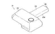
図1、図2に示すように、フロアパネル4の前席30に対応する部位には、床面(足元部が構成される面:基準面)に対して車室側(上側)に膨出する膨出部7が形成されている。膨出部7は車幅方向、略車幅方向(運転席及び助手席の幅程度)に延びて形成され、膨出部7の上面に前席30(運転席及び助手席)が設置される。膨出部7に連続して車両の中央部で後ろ側に延びて車室側(上側)に膨出しトンネル状をなす前後膨出部8が形成されている。尚、前後膨出部8は膨出部7に比べ車両の幅方向寸法が小さく、即ち、幅が狭くされている。具体的には運転席と助手席との隙間程度の幅である。フロアパネル4の膨出部7及び前後膨出部8の下側に車両用燃料タンク(燃料タンク)21が配置されている。
As shown in FIGS. 1 and 2, the portion corresponding to the
尚、上述した実施形態例では、前後方向に2列の座席を有する車両を例に挙げて説明したが、3列以上の複数列の座席を有する車両に適用することも可能であり、膨出部7は最後列より前側の座席の部位に対応して設けることが可能である。また、前後膨出部8を膨出部7の後ろ側に設けた例を挙げて説明したが、前後膨出部8を膨出部7の前側、もしくは、前側及び後ろ側に設けることも可能である。
In the above-described embodiment, the vehicle having two rows of seats in the front-rear direction has been described as an example. However, the embodiment can be applied to a vehicle having three or more rows of seats, and the bulge The
フロアパネル4の表面の適宜部位には車幅方向に延びる横リブ9が形成され、膨出部7の前側(前席30の乗員の足元部)のフラットな部位には、車幅方向に延びて車両の中央部をまたぐ状態のリブ10が形成されている。更に、リブ10の両側には車両の前後方向に延びる前後リブ11が形成されている。
A
上述したフロアパネル4は、前後膨出部8を膨出部7の後ろ側に設け、前後膨出部8の前側(前席30の乗員の足元部)をフラットな状態にしている。このため、膨出部7によりデッドスペースである前席30の下部を燃料タンク11の配置スペースとすることができ、足元スペースの要求の厳しい前側をフラットな状態にすることができる。そして、前後膨出部8でフロアパネル4の全体の剛性が確保される。
In the floor panel 4 described above, the front /
特に、サイドメンバ2同士の幅は車両中央部近傍から狭幅部2aに向かい漸次幅が減少して構成されているので、前側のサイドメンバ2同士の幅が短く前側(前席30の乗員の足元部)をフラットな状態にしてもサイドメンバ2と共にフロアパネル4の剛性を確保することができる。更に、車両の中央部をまたぐ状態のリブ10が形成されているので、膨出部を形成することなくフロアパネル4の剛性を確保することができ、前後リブ11により剛性の確保を確実にすることができる。
In particular, the width between the
図3乃至図8に基づいて燃料タンク21を説明する。
The
図3乃至図6に示すように、燃料タンク21は、車両の幅方向に延びフロアパネル4の膨出部7の下部に配置される本体部22を備え、本体部22の車幅方向の中央部に連続して車両の後ろ側に延びる前後部23が形成されている。前後部23は前後膨出部8の下部に配置される。燃料タンク21は、本体部22及び前後部23が、例えば、射出成形により一体に形成されている。本体部22は車幅方向で膨出部7と略同じ幅とされ膨出部7に収まっている。
As shown in FIGS. 3 to 6, the
図5に示すように、前後部23の下面23aは本体部22の下面22aより上方に位置して設けられている。また、図6に示すように、本体部22は車幅方向の片側の下面22aが前後部23の下面23aよりも下方に位置し、他側の下面22bは前後部23の下面23aと略同じ高さとなっている。このため、燃料が少なくなった際には本体部22の車幅方向の片側の下面22a側だけに残燃料が溜り、供給用のポンプ等の供給手段を複数設ける必要がない。
As shown in FIG. 5, the lower surface 23 a of the front and
図7に示すように、燃料タンク21の前後部23の後端はフロアパネル4の後端部に位置し、前後部23の後端部には接続部24が設けられ、接続部24には図示しない給油口から延びるフィラーパイプ25が接続されている。このため、給油口を車両の後部に設けることで、フィラーパイプ25を燃料タンク21までつなげるための特別な工夫が不要で、フィラーパイプ25を短くすることができる。
As shown in FIG. 7, the rear end of the front and
図7、図8に示すように、燃料タンク21の前後部23は燃料タンク21の後ろ側のクロスメンバ3の上方に配されている。前後部23は、例えば、射出成形により形成されているために、低くするには(薄くするには)限度があり、また、前後膨出部8の高さにも限度があり、前後部23の底面23aの高さはフロアパネル4の基準面(足元部となる平面)よりも低い位置にある。このため、図8に示すように、クロスメンバ3の上面には前後部23が配置される凹部27が形成されている。
As shown in FIGS. 7 and 8, the front and
このため、クロスメンバ3の補強作用に影響を及ぼすことがなく横方向の補強を的確に行うことができる。
For this reason, it is possible to accurately perform the lateral reinforcement without affecting the reinforcing action of the
また、燃料タンク21の本体部22の上部にはブリーザパイプ26が接続され、ブリーザパイプ26は前後膨出部8の下側で前後部23の上面に沿って配置され、更に、フロアパネル4より後方(図示省略)で給油口近傍のフィラーパイプ25まで延びている。このため、ブリーザパイプ26を複雑な形状にすることなく高い位置に保持することができ、給油時のエア抜きを的確に行うことができる。
Further, a
上述した構成では、前後膨出部8が車室内における後席の足元部の中央部に存在することになるが、後席の足元部の中央部にはプロペラシャフト等が貫通する凸状の部材が存在する車種もあり、後席の足元部の中央部は前後膨出部8が存在しても乗員に違和感を与える虞がほとんどない場所となっている。このため、燃料タンク21の前後部23を配置するための前後膨出部8が車室内における後席の足元部の中央部に存在しても商品性を損なうことがない。
In the above-described configuration, the front and rear bulging
上記構成の構造では、前席30側に対応する部位のフロアパネル4に、床面に対して車室側に膨らむ膨出部7を形成すると共に、膨出部7に連続して車両の後方向に延びて車室側に膨らむ前後膨出部8を形成し、本体部22に連続して車両の後方向に延びる前後部23が設けられた燃料タンク21を適用し、膨出部7の下部に燃料タンク21の本体部22を配置すると共に前後膨出部8の下部に前後部23を配置したので、前後部23の容積により燃料タンク21の容量を増やすことができると共に、前後方向のタンクの長さを長くすることができる。
In the structure having the above configuration, the floor panel 4 corresponding to the
これにより、制動時や加速時に燃料タンク21の内部で燃料が車両前後方向に波打つ周期が長くなり、前後の壁面に波が当たって落下する際に発生する滴下音(流動音)の頻度を低下させることができる。また、燃料の波が前後の壁面間を移動する距離が長くなり波が減衰されて流動音の大きさを低下させることができる。また、前後膨出部8は車両の後方向に延びているため車室内に膨出しても違和感が生じない。
This increases the period in which the fuel undulates in the longitudinal direction of the vehicle during braking and acceleration, and reduces the frequency of dripping sound (flowing sound) that occurs when waves hit the front and rear walls and fall. Can be made. In addition, the distance that the fuel wave travels between the front and rear wall surfaces becomes longer, the wave is attenuated, and the magnitude of the flow noise can be reduced. Further, since the front and rear bulging
このため、床下に配置しても容量を十分に確保することができ、しかも、燃料流動音を抑制することができる燃料タンク21とすることが可能になる。従って、床下に燃料タンク21を配置しても、商品性を損なうことなく容量を十分に確保することができ、しかも、燃料流動音を抑制することができる車両用燃料タンクの配置構造とすることが可能になる。
For this reason, even if it arrange | positions under a floor, it can be set as the
また、燃料タンク21の前後部23の後端は、最後列の座席の足元部まで延びるフロアパネル4の後端の位置に延びているので、前後部23の前後方向の長さが長くなり、燃料タンク21の容量を効果的に増やすことができる。
Moreover, since the rear end of the front and
また、燃料タンク21の前後部23の下面は本体部22の下面より上方に位置し、前後部23はクロスメンバ3の上方に配されているので、クロスメンバ3の補強作用に影響を及ぼすことがなく横方向の補強を的確に行うことができる。また、本体部22と前後部23の底面の段差により燃料の波打ち状態が減衰され、流動音の抑制を効果的に行うことができる。
Further, since the lower surface of the front and
また、燃料タンク21の前後部23の端部に給油口と燃料タンク21とをつなぐフィラーパイプ25を接続したので、フィラーパイプ25を燃料タンク21までつなげるための特別な工夫が不要で、車両の後方(前後部23が延びる方向)に給油口を備えることでフィラーパイプ25を短くすることができる。
In addition, since the
床下に配置しても容量を十分に確保することができ、しかも、燃料流動音を抑制することができる車両用燃料タンクとすることができる。 Even if it is placed under the floor, a sufficient capacity can be secured, and a fuel tank for a vehicle that can suppress fuel flow noise can be obtained.
床下に燃料タンクを配置しても、商品性を損なうことなく容量を十分に確保することができ、しかも、燃料流動音を抑制することができる車両用燃料タンクの配置構造とすることができる。 Even if the fuel tank is arranged under the floor, a sufficient capacity can be secured without impairing the merchantability, and the fuel fuel tank arrangement structure can suppress the fuel flow noise.
1 車体フレーム
2 サイドメンバ
3 クロスメンバ
4 フロントフロアパネル(フロアパネル)
5 ダッシュパネル
6 リヤフロアパネル
7 膨出部
8 前後膨出部
9 横リブ
10 リブ
21 燃料タンク
22 本体部
23 前後部
24 接続部
25 フィラーパイプ
26 ブリーザパイプ
27 凹部
30 前席
1
DESCRIPTION OF SYMBOLS 5
Claims (3)
前記膨出部及び前記前後膨出部の下側に車両用燃料タンクを配し、
前記燃料タンクは、車両の幅方向に延び前記フロアパネルの前記膨出部の下部に配置される本体部を備えると共に該本体部に連続して車両の前後方向に延び前記フロアパネルの前記前後膨出部の下部に配置される前後部が前記本体部に連続して備えられている車両用燃料タンクの配置構造において、
前記車両用燃料タンクの前記前後部の端部に給油口と車両用燃料タンクとをつなぐフィラーパイプを接続した
ことを特徴とする車両用燃料タンクの配置構造。 A bulging portion that bulges toward the passenger compartment side with respect to the floor surface is formed at a portion corresponding to the front seat side of the floor panel of the vehicle having at least two rows of seats in the longitudinal direction of the vehicle, and is continuous with the bulging portion. Extending in the front-rear direction of the vehicle and bulging toward the passenger compartment side to form a front-rear bulge portion narrower in the vehicle width direction than the bulge portion;
A vehicle fuel tank is disposed below the bulging portion and the front and rear bulging portions,
The fuel tank includes a main body portion that extends in a vehicle width direction and is disposed at a lower portion of the bulging portion of the floor panel, and extends in the front-rear direction of the vehicle continuously to the main body portion. In the vehicle fuel tank arrangement structure in which the front and rear parts arranged in the lower part of the protruding part are continuously provided in the main body part ,
An arrangement structure of a vehicle fuel tank, wherein a filler pipe that connects a fuel filler port and a vehicle fuel tank is connected to end portions of the front and rear portions of the vehicle fuel tank.
前記フロアパネルは最後列の座席の足元部まで延びるフロント側のフロアパネルであり、
前記車両用燃料タンクの前記前後部は前記本体部の車両後ろ側に延びて設けられ、
該前後部の後端は前記フロアパネルの後端部に位置する
ことを特徴とする車両用燃料タンクの配置構造。 The vehicle fuel tank arrangement structure according to claim 1 ,
The floor panel is a front side floor panel extending to the foot of the last row of seats,
The front and rear parts of the vehicle fuel tank are provided extending to the vehicle rear side of the main body part,
The vehicle fuel tank arrangement structure, wherein the rear ends of the front and rear portions are located at the rear end of the floor panel.
前記フロアパネルはサイドメンバ及びクロスメンバからなる骨格部材に備えられ、
前記車両用燃料タンクの前記前後部の下面は前記本体部の下面より上方に位置し、
前記前後部は前記クロスメンバの上方に配されている
ことを特徴とする車両用燃料タンクの配置構造。 The vehicle fuel tank arrangement structure according to claim 2 ,
The floor panel is provided in a skeleton member composed of a side member and a cross member,
The lower surface of the front and rear portions of the vehicle fuel tank is located above the lower surface of the main body,
The arrangement of the fuel tank for vehicles, wherein the front and rear portions are arranged above the cross member.
Priority Applications (1)
| Application Number | Priority Date | Filing Date | Title |
|---|---|---|---|
| JP2003432194A JP4269937B2 (en) | 2003-12-26 | 2003-12-26 | Vehicle fuel tank arrangement structure |
Applications Claiming Priority (1)
| Application Number | Priority Date | Filing Date | Title |
|---|---|---|---|
| JP2003432194A JP4269937B2 (en) | 2003-12-26 | 2003-12-26 | Vehicle fuel tank arrangement structure |
Publications (2)
| Publication Number | Publication Date |
|---|---|
| JP2005186833A JP2005186833A (en) | 2005-07-14 |
| JP4269937B2 true JP4269937B2 (en) | 2009-05-27 |
Family
ID=34789969
Family Applications (1)
| Application Number | Title | Priority Date | Filing Date |
|---|---|---|---|
| JP2003432194A Expired - Fee Related JP4269937B2 (en) | 2003-12-26 | 2003-12-26 | Vehicle fuel tank arrangement structure |
Country Status (1)
| Country | Link |
|---|---|
| JP (1) | JP4269937B2 (en) |
Families Citing this family (3)
| Publication number | Priority date | Publication date | Assignee | Title |
|---|---|---|---|---|
| JP4529464B2 (en) * | 2004-02-12 | 2010-08-25 | マツダ株式会社 | Vehicle fuel tank arrangement structure |
| JP5994143B2 (en) * | 2012-12-19 | 2016-09-21 | トヨタ車体株式会社 | Vehicle floor structure |
| JP7087253B2 (en) * | 2018-11-06 | 2022-06-21 | トヨタ車体株式会社 | Vehicle floor structure |
-
2003
- 2003-12-26 JP JP2003432194A patent/JP4269937B2/en not_active Expired - Fee Related
Also Published As
| Publication number | Publication date |
|---|---|
| JP2005186833A (en) | 2005-07-14 |
Similar Documents
| Publication | Publication Date | Title |
|---|---|---|
| JP4175107B2 (en) | Vehicle floor panel | |
| JP5005418B2 (en) | Fuel tank piping structure | |
| BRPI0618190A2 (en) | vehicle body bottom structure | |
| KR20030081038A (en) | Car body structure | |
| JP2017124656A (en) | Vehicle body structure of vehicle | |
| JP4342189B2 (en) | Auto body front structure | |
| JP4678473B2 (en) | Vehicle fuel tank arrangement structure | |
| JPH08244479A (en) | Fuel tank for vehicle | |
| JPS5849519A (en) | Body floor structure of automobile | |
| JP4269937B2 (en) | Vehicle fuel tank arrangement structure | |
| JP5604996B2 (en) | Body panel reinforcement structure | |
| JP4296931B2 (en) | Vehicle floor structure | |
| JP4703711B2 (en) | Automotive floorboard structure | |
| JPH10264864A (en) | Floor structure of automobile | |
| JP4251568B2 (en) | Lower body structure of the vehicle | |
| JP4238725B2 (en) | Vehicle structure | |
| JP4635690B2 (en) | Auxiliary equipment arrangement structure of vehicle | |
| JP4251569B2 (en) | Vehicle body structure | |
| JP2007106229A (en) | Seat arranging structure of vehicle | |
| JP7015476B2 (en) | Roof panel and roof structure | |
| JP3924768B2 (en) | Rear body structure of the vehicle | |
| JP4286797B2 (en) | Car body floor panel | |
| JP6230398B2 (en) | Automotive floor front structure | |
| JP7302121B2 (en) | Vehicle luggage compartment structure | |
| JP2005255070A (en) | Suspension cross-member of vehicle |
Legal Events
| Date | Code | Title | Description |
|---|---|---|---|
| A621 | Written request for application examination |
Free format text: JAPANESE INTERMEDIATE CODE: A621 Effective date: 20060324 |
|
| A131 | Notification of reasons for refusal |
Free format text: JAPANESE INTERMEDIATE CODE: A131 Effective date: 20081118 |
|
| A521 | Written amendment |
Free format text: JAPANESE INTERMEDIATE CODE: A523 Effective date: 20090113 |
|
| TRDD | Decision of grant or rejection written | ||
| A01 | Written decision to grant a patent or to grant a registration (utility model) |
Free format text: JAPANESE INTERMEDIATE CODE: A01 Effective date: 20090203 |
|
| A01 | Written decision to grant a patent or to grant a registration (utility model) |
Free format text: JAPANESE INTERMEDIATE CODE: A01 |
|
| A61 | First payment of annual fees (during grant procedure) |
Free format text: JAPANESE INTERMEDIATE CODE: A61 Effective date: 20090216 |
|
| FPAY | Renewal fee payment (event date is renewal date of database) |
Free format text: PAYMENT UNTIL: 20120306 Year of fee payment: 3 |
|
| R150 | Certificate of patent or registration of utility model |
Ref document number: 4269937 Country of ref document: JP Free format text: JAPANESE INTERMEDIATE CODE: R150 Free format text: JAPANESE INTERMEDIATE CODE: R150 |
|
| FPAY | Renewal fee payment (event date is renewal date of database) |
Free format text: PAYMENT UNTIL: 20120306 Year of fee payment: 3 |
|
| FPAY | Renewal fee payment (event date is renewal date of database) |
Free format text: PAYMENT UNTIL: 20130306 Year of fee payment: 4 |
|
| FPAY | Renewal fee payment (event date is renewal date of database) |
Free format text: PAYMENT UNTIL: 20140306 Year of fee payment: 5 |
|
| LAPS | Cancellation because of no payment of annual fees |