JP4266760B2 - Ride type rice transplanter - Google Patents
Ride type rice transplanter Download PDFInfo
- Publication number
- JP4266760B2 JP4266760B2 JP2003332228A JP2003332228A JP4266760B2 JP 4266760 B2 JP4266760 B2 JP 4266760B2 JP 2003332228 A JP2003332228 A JP 2003332228A JP 2003332228 A JP2003332228 A JP 2003332228A JP 4266760 B2 JP4266760 B2 JP 4266760B2
- Authority
- JP
- Japan
- Prior art keywords
- seedling
- support member
- left support
- rice transplanter
- changed
- Prior art date
- Legal status (The legal status is an assumption and is not a legal conclusion. Google has not performed a legal analysis and makes no representation as to the accuracy of the status listed.)
- Expired - Fee Related
Links
Images


Landscapes
- Transplanting Machines (AREA)
- Agricultural Machines (AREA)
Description
本発明は、苗のせ面に載置された苗に上方から薬剤(殺虫剤や殺菌剤等)又は肥料を供給する供給装置を備えた乗用型田植機に関する。 The present invention relates to a riding type rice transplanter provided with a supply device for supplying medicine (insecticide, fungicide, etc.) or fertilizer from above to seedlings placed on the seedling surface.
乗用型田植機においては例えば特許文献1に開示されているように、支持部材(特許文献1の図2,3,4中の27)を、苗のせ台(特許文献1の図1,2,3,4中の14)に苗のせ面(特許文献1の図3中の14a)の上側に亘って配置されるように支持し、供給装置(特許文献1の図1,2,3,4中の30)を、支持部材に沿って往復移動自在に備えて、供給装置を支持部材に沿って往復駆動する駆動機構(特許文献1の図1,2,3,4中の40,44)を支持部材に備えたものがある。
これにより、供給装置が支持部材に沿って往復移動しながら、供給装置から苗のせ台に載置された苗に上方から薬剤又は肥料が供給される。
In a riding type rice transplanter, for example, as disclosed in
Thereby, a chemical | medical agent or a fertilizer is supplied from the upper direction to the seedling mounted on the seedling stand from a supply apparatus, a supply apparatus reciprocatingly moving along a support member.
特許文献1のような供給装置、支持部材及び駆動機構を乗用型田植機に備える場合、例えば8条型式や10条型式等の横幅の大きな苗のせ台において、苗のせ台の全幅に亘るような長い一つの支持部材を備えると、供給装置が支持部材の右端部から左端部(左端部から右端部)に移動するのに時間を要してしまうので、苗のせ台に載置された苗に薬剤又は肥料を均等に供給することが困難なものになることがある(例えば、供給装置が薬剤又は肥料を供給しながら支持部材の右端部から左端部に移動し始めた際、供給装置が支持部材の左端部に達するまでに、縦送り機構によって苗のせ台に載置された苗が何回も下方に送られてしまうと、支持部材の左端部の付近において、薬剤又は肥料が供給されない苗の部分の生じることがある)。又、苗のせ台の全幅に亘るような長い一つの支持部材を備えると、支持部材の強度面で不安が生じる。
When the riding device is equipped with a supply device, a support member, and a drive mechanism as in
本発明は乗用型田植機において、供給装置、支持部材及び駆動機構を備える場合、例えば8条型式や10条型式等の横幅の大きな苗のせ台でも、苗のせ台に載置された苗に薬剤又は肥料が適切に供給されるように構成することを目的としている。 In the riding type rice transplanter, the present invention includes a feeding device, a support member, and a drive mechanism. For example, even in a seedling table having a large width such as an eight-row type or a ten-row type, a drug is applied to the seedling placed on the seedling table. Or it aims at comprising so that fertilizer may be supplied appropriately.
[I]
(構成)
本発明の第1特徴は、多数の苗のせ面を備えた苗のせ台を備え、苗のせ面から苗を取り出して田面に植え付ける植付アームを苗のせ面の各々に対応して備えた乗用型田植機において、次のように構成することにある。
右の所定数の苗のせ面の上側に亘って配置されるように苗のせ台に支持された右の支持部材、右の支持部材に沿って往復移動自在に備えられた右の供給装置、右の支持部材に備えられて右の供給装置を右の支持部材に沿って往復駆動する右の駆動機構を備える。左の所定数の苗のせ面の上側に亘って配置されるように苗のせ台に支持された左の支持部材、左の支持部材に沿って往復移動自在に備えられた左の供給装置、左の支持部材に備えられて左の供給装置を左の支持部材に沿って往復駆動する左の駆動機構を備える。右及び左の供給装置が右及び左の支持部材に沿って往復移動しながら、右及び左の所定数の苗のせ面に載置された苗に上方から薬剤又は肥料を供給するように構成する。苗のせ台の右又は左側部分の位置を変更可能に構成して、苗のせ台の横幅を作業状態の苗のせ台の横幅よりも狭いものに設定可能に構成し、位置変更される側の右又は左の支持部材を苗のせ台から取り外し自在に構成する。
[I]
(Constitution)
The first feature of the present invention is a riding type provided with a seedling platform having a large number of seedling surfaces, and provided with planting arms for taking out the seedlings from the seedling surfaces and planting them on the rice field corresponding to each of the seedling surfaces. The rice transplanter is configured as follows.
A right support member supported by a seedling platform so as to be arranged over a predetermined number of seedling surfaces on the right, a right supply device provided to be reciprocally movable along the right support member, and right And a right drive mechanism that reciprocates the right supply device along the right support member. Left support member supported by a seedling platform so as to be arranged over the upper surface of a predetermined number of seedling surfaces on the left, left supply device provided to be reciprocally movable along the left support member, left And a left drive mechanism that reciprocates the left supply device along the left support member. The right and left supply devices are configured to supply medicine or fertilizer from above to the seedlings placed on a predetermined number of seedling surfaces on the right and left while reciprocating along the right and left support members. . The position of the right or left side of the seedling platform is configured to be changeable, and the width of the seedling platform is configured to be narrower than the width of the seedling platform in the working state. Alternatively, the left support member is configured to be removable from the seedling table.
(作用)
本発明の第1特徴によると、右及び左の所定数の苗のせ面の上側に亘って配置されるように、右及び左の支持部材が苗のせ台に支持されて、右及び左の支持部材に右及び左の供給装置が往復移動自在に備えられ、右及び左の供給装置を右及び左の支持部材に沿って往復駆動する右及び左の駆動機構が右及び左の支持部材に備えられるのであり、右の所定数の苗のせ面に載置された苗に対して右の供給装置から薬剤又は肥料が供給され、左の所定数の苗のせ面に載置された苗に対して左の供給装置から薬剤又は肥料が供給される。
(Function)
According to the first aspect of the present invention, the right and left support members are supported by the seedling platform so as to be arranged over the predetermined number of seedling surfaces on the right and left, and the right and left supports are supported. The right and left supply devices are provided on the right and left support members, and the right and left supply devices are provided on the right and left support members to reciprocate along the right and left support members. With respect to the seedlings placed on the left predetermined number of seedlings, the medicine or fertilizer is supplied from the right supply device to the seedlings placed on the right predetermined number of seedlings. A drug or fertilizer is supplied from the supply device on the left.
これにより、本発明の第1特徴によると、右及び左の供給装置は苗のせ台の全幅に亘って往復移動しないので(右及び左の所定数の苗のせ面に亘って往復移動するので)、右及び左の供給装置は右及び左の支持部材の右端部から左端部(左端部から右端部)に比較的速く達する。従って、例えば右の供給装置が薬剤又は肥料を供給しながら右の支持部材の右端部から左端部に移動し始めた際、右の供給装置が右の支持部材の左端部に達するまでに、縦送り機構によって苗のせ台に載置された苗が何回も下方に送られてしまうと言うような状態が生じ難くなるのであり、苗のせ台に載置された苗に薬剤又は肥料が均等に供給され易くなる。
本発明の第1特徴によると、苗のせ台の全幅に亘るような長い一つの支持部材を備えるのではなく、右及び左の支持部材に分けているので、右及び左の支持部材が不必要に長いものにならない。
Thus, according to the first feature of the present invention, the right and left feeding devices do not reciprocate over the entire width of the seedling platform (since they reciprocate over a predetermined number of seedling surfaces on the right and left). The right and left feeding devices reach relatively quickly from the right end to the left end (left end to right end) of the right and left support members. Therefore, for example, when the right supply device starts to move from the right end portion of the right support member to the left end portion while supplying the drug or fertilizer, the right supply device reaches the left end portion of the right support member until the right supply device reaches the left end portion. It is difficult for the seedlings placed on the seedling table to be sent down many times by the feeding mechanism, and the drug or fertilizer is evenly distributed on the seedlings placed on the seedling table. It becomes easy to be supplied.
According to the first feature of the present invention, the right and left support members are not necessary because the support members are divided into right and left support members rather than having a single long support member extending over the entire width of the seedling platform. It will not be long.
乗用型田植機では、苗のせ台の右又は左側部分の位置を変更可能に構成して(例えば前のせ台の右又は左側部分を分離させて他方の右又は左側部分の上側に乗せたり、苗のせ台の右又は左側部分を上向き(又は下向き)に折り曲げたりして)、苗のせ台の横幅を作業状態の苗のせ台の横幅よりも狭いものに設定可能に構成したものがある。
本発明の第1特徴によると、位置変更される側の右又は左の支持部材を苗のせ台から取り外し自在に構成しているので(位置変更される側の右又は左の供給装置及び駆動機構も右又は左の支持部材と一緒に取り外される)、前述のように苗のせ台の右又は左側部分の位置を変更して、苗のせ台の横幅を作業状態の苗のせ台の横幅よりも狭いものに設定した場合、位置変更される側の右又は左の支持部材を苗のせ台から取り外すことによって、位置変更される側の右又は左の支持部材が苗のせ台の横幅の範囲から横側に出ると言うような状態を避けることができる。
The riding type rice transplanter is configured so that the position of the right or left side of the seedling platform can be changed (for example, the right or left side of the front platform is separated and placed on the upper side of the other right or left side. There is a configuration in which the lateral width of the seedling platform is set to be narrower than the lateral width of the seedling platform in the working state by folding the right or left part of the platform upward (or downward).
According to the first aspect of the present invention, the right or left support member on the side to be repositioned is configured to be detachable from the seedling table (the right or left supply device and drive mechanism on the side to be repositioned) The right or left support member is removed together with the right or left support member), and the right or left side of the seedling platform is changed as described above, so that the width of the seedling platform is narrower than the width of the working seedling platform. If set to one, the right or left support member on the side to be repositioned is removed from the seedling platform, so that the right or left support member on the side to be repositioned is lateral from the width range of the seedling platform. You can avoid the situation of going out.
(発明の効果)
本発明の第1特徴によると、乗用型田植機において、右及び左の供給装置、右及び左の支持部材、右及び左の駆動機構を備えることにより、苗のせ台に載置された苗に薬剤又は肥料が均等に供給され易くなって、苗のせ台に載置された苗への薬剤又は肥料の供給性能を向上させることができた。右及び左の支持部材が不必要に長いものにならないので、右及び左の支持部材の強度面での不安を解消することができた。
(The invention's effect)
According to the first feature of the present invention, in the riding type rice transplanter, the right and left feeding devices, the right and left support members, and the right and left drive mechanisms are provided, so that the seedling placed on the seedling platform is provided. The drug or fertilizer can be easily supplied evenly, and the supply performance of the drug or fertilizer to the seedlings placed on the seedling table can be improved. Since the right and left support members do not become unnecessarily long, the anxiety in terms of the strength of the right and left support members could be eliminated.
本発明の第1特徴によると、苗のせ台の右又は左側部分の位置を変更して、苗のせ台の横幅を作業状態の苗のせ台の横幅よりも狭いものに設定した場合に、位置変更される側の右又は左の支持部材を苗のせ台から取り外すことにより(位置変更される側の右又は左の供給装置及び駆動機構も右又は左の支持部材と一緒に取り外される)、位置変更される側の右又は左の支持部材が苗のせ台の横幅の範囲から横側に出ると言うような状態を避けることができて、苗植付装置の全体をコンパクトなものにまとめることができるようになった。 According to the first feature of the present invention, when the position of the right or left part of the seedling platform is changed and the lateral width of the seedling platform is set to be narrower than the lateral width of the seedling platform in the working state, the position is changed. Change the position by removing the right or left support member from the seedling stand (the right or left feeding device and drive mechanism on the side to be repositioned are also removed together with the right or left support member) Can prevent the situation where the right or left support member on the side to be used goes out from the lateral width range of the seedling platform, and the whole seedling planting device can be integrated into a compact one It became so.
[II]
(構成)
本発明の第2特徴は、本発明の第1特徴の乗用型田植機において次のように構成することにある。
位置変更される側の右又は左の支持部材を苗のせ台から取り外して、位置変更されない側の右又は左の支持部材の後側に取り付け可能に構成する。
[II]
(Constitution)
The second feature of the present invention resides in the following configuration in the riding rice transplanter of the first feature of the present invention.
The right or left support member on the side whose position is to be changed is removed from the seedling stage and can be attached to the rear side of the right or left support member on which the position is not changed.
(作用)
本発明の第2特徴によると、本発明の第1特徴と同様に前項[I]に記載の「作用」を備えており、これに加えて以下のような「作用」を備えている。
本発明の第2特徴によると、前項[I]に記載のように、苗のせ台の右又は左側部分の位置を変更して、苗のせ台の横幅を作業状態の苗のせ台の横幅よりも狭いものに設定した場合、位置変更される側の右又は左の支持部材を苗のせ台から取り外して、位置変更されない側の右又は左の支持部材の後側に取り付けることができるので、位置変更される側の右又は左の支持部材の保管に困ることがない。
(Function)
According to the second feature of the present invention, the “action” described in the preceding item [I] is provided in the same manner as the first feature of the present invention, and in addition to this, the following “action” is provided.
According to the second feature of the present invention, as described in the preceding item [I], the position of the right or left side of the seedling platform is changed so that the lateral width of the seedling platform is larger than the lateral width of the seedling platform in the working state. When set to a narrow one, the right or left support member on the side to be repositioned can be removed from the seedling base and attached to the rear side of the right or left support member on the non-reposition side. There is no problem in storing the right or left support member on the side to be used.
(発明の効果)
本発明の第2特徴によると、本発明の第1特徴と同様に前項[I]に記載の「発明の効果」を備えており、これに加えて以下のような「発明の効果」を備えている。
本発明の第2特徴によると、位置変更される側の右又は左の支持部材を苗のせ台から取り外した場合、位置変更される側の右又は左の支持部材の保管に困ることがなくなって、使い易さを向上させることができた。
(The invention's effect)
According to the second feature of the present invention, the “effect of the invention” described in the preceding item [I] is provided in the same manner as the first feature of the present invention. In addition, the following “effect of the invention” is provided. ing.
According to the second aspect of the present invention, when the right or left support member on the side to be repositioned is removed from the seedling table, there is no problem in storing the right or left support member on the side to be repositioned. And improved usability.
[III]
(構成)
本発明の第3特徴は、本発明の第2特徴の乗用型田植機において次のように構成することにある。
位置変更される側の右又は左の支持部材を苗のせ台から取り外し、位置変更されない側の右又は左の支持部材の後側に取り付けた状態において、位置変更される側の右又は左の支持部材が接地フロートの後端よりも前側に位置するように構成する。
[III]
(Constitution)
The third feature of the present invention resides in the following configuration in the riding type rice transplanter of the second feature of the present invention.
The right or left support on the side to be repositioned in a state where the right or left support member on the side to be repositioned is removed from the seedling table and attached to the rear side of the right or left support member on the side that is not repositioned. The member is configured to be positioned in front of the rear end of the ground float.
(作用)
本発明の第3特徴によると、本発明の第2特徴と同様に前項[I][II]に記載の「作用」を備えており、これに加えて以下のような「作用」を備えている。
本発明の第3特徴によると、前項[II]に記載のように、位置変更される側の右又は左の支持部材を苗のせ台から取り外して、位置変更されない側の右又は左の支持部材の後側に取り付けた場合、位置変更される側の右又は左の支持部材が接地フロートの後端よりも前側に位置するので、位置変更される側の右又は左の支持部材が苗植付装置の範囲から後側に出ると言うようなことがない。
(Function)
According to the third feature of the present invention, as in the second feature of the present invention, the “action” described in the preceding paragraphs [I] and [II] is provided. In addition, the following “action” is provided. Yes.
According to the third aspect of the present invention, as described in [II] above, the right or left support member on the side whose position is to be changed is removed from the seedling table, and the right or left support member on the side whose position is not changed is removed. When attached to the rear side, the right or left support member on the side to be repositioned is located in front of the rear end of the grounding float, so the right or left support member on the side to be repositioned is planted. There is no such thing as going out from the range of the device.
(発明の効果)
本発明の第3特徴によると、本発明の第2特徴と同様に前項[I][II]に記載の「発明の効果」を備えており、これに加えて以下のような「発明の効果」を備えている。
本発明の第3特徴によると、位置変更される側の右又は左の支持部材を苗のせ台から取り外して、位置変更されない側の右又は左の支持部材の後側に取り付けた場合、位置変更される側の右又は左の支持部材が苗植付装置の範囲から後側に出ると言うようなことがないので、苗植付装置の全体をコンパクトなものにまとめることができるようになった。
(The invention's effect)
According to the third feature of the present invention, the “effect of the invention” described in the preceding paragraphs [I] and [II] is provided in the same manner as the second feature of the present invention. In addition, the following “effect of the invention” is provided. Is provided.
According to the third aspect of the present invention, when the right or left support member on the side to be repositioned is removed from the seedling table and attached to the rear side of the right or left support member on the non-reposition side, the position change is performed. Since the right or left support member on the side to be used does not come out rearward from the range of the seedling planting device, the entire seedling planting device can be combined into a compact one .
[IV]
(構成)
本発明の第4特徴は、本発明の第2又は第3特徴の乗用型田植機において次のように構成することにある。
位置変更される側の右又は左の支持部材を取り付ける為の取付部を、植付アームを備えた伝動ケースに備える。
[IV]
(Constitution)
A fourth feature of the present invention resides in the following configuration in the riding type rice transplanter of the second or third feature of the present invention.
An attachment part for attaching a right or left support member on the side whose position is to be changed is provided in a transmission case provided with a planting arm.
(作用)
本発明の第4特徴によると、本発明の第2又は第3特徴と同様に前項[I]〜[III]に記載の「作用」を備えており、これに加えて以下のような「作用」を備えている。
本発明の第4特徴によると、前項[II][III]に記載のように、位置変更される側の右又は左の支持部材を苗のせ台から取り外して、位置変更されない側の右又は左の支持部材の後側に取り付けた場合、位置変更される側の右又は左の支持部材を取り付ける為の取付部が、植付アームを備えた伝動ケースに備えられている。この場合、伝動ケースは充分な強度で構成されているので、位置変更される側の右又は左の支持部材が充分な強度で伝動ケースに支持される。
(Function)
According to the fourth feature of the present invention, the “action” described in the preceding paragraphs [I] to [III] is provided in the same manner as the second or third feature of the present invention. Is provided.
According to the fourth aspect of the present invention, as described in [II] and [III] above, the right or left support member on the side whose position is to be changed is removed from the seedling table, and the right or left side on which the position is not changed is removed. When attached to the rear side of the support member, an attachment portion for attaching the right or left support member on the side whose position is to be changed is provided in a transmission case provided with a planting arm. In this case, since the transmission case is configured with sufficient strength, the right or left support member on the side whose position is to be changed is supported by the transmission case with sufficient strength.
(発明の効果)
本発明の第4特徴によると、本発明の第2又は第3特徴と同様に前項[I]〜[III]に記載の「発明の効果」を備えており、これに加えて以下のような「発明の効果」を備えている。
本発明の第4特徴によると、位置変更される側の右又は左の支持部材を苗のせ台から取り外して、位置変更されない側の右又は左の支持部材の後側に取り付けた場合、位置変更される側の右又は左の支持部材が充分な強度で伝動ケースに支持されるようになって、位置変更される側の右又は左の支持部材の支持強度の面で有利なものとなった。
(The invention's effect)
According to the fourth feature of the present invention, the “effect of the invention” described in the preceding paragraphs [I] to [III] is provided in the same manner as the second or third feature of the present invention. “Effect of the invention” is provided.
According to the fourth aspect of the present invention, when the right or left support member on the side to be repositioned is removed from the seedling base and attached to the rear side of the right or left support member on the non-reposition side, the position change is performed. The right or left support member on the side to be moved is supported by the transmission case with sufficient strength, which is advantageous in terms of the support strength of the right or left support member on the side to be repositioned. .
[V]
(構成)
本発明の第5特徴は、本発明の第1〜第4特徴の乗用型田植機のうちのいずれか一つにおいて次のように構成することにある。
右の支持部材を苗のせ台に支持する支持ブラケットと、左の支持部材を苗のせ台に支持する支持ブラケットとを同じものに構成する。
[V]
(Constitution)
The fifth feature of the present invention resides in the following configuration in any one of the riding rice transplanters of the first to fourth features of the present invention.
The support bracket that supports the right support member on the seedling platform and the support bracket that supports the left support member on the seedling platform are configured to be the same.
(作用)
本発明の第5特徴によると、本発明の第1〜第4特徴のうちのいずれか一つと同様に前項[I]〜[IV]に記載の「作用」を備えており、これに加えて以下のような「作用」を備えている。
本発明の第5特徴によると、右及び左の支持部材を苗のせ台に支持させる場合、右及び左の支持部材において支持ブラケットが兼用される。
(Function)
According to the fifth aspect of the present invention, the “action” described in the preceding paragraphs [I] to [IV] is provided similarly to any one of the first to fourth characteristics of the present invention. It has the following “actions”.
According to the fifth feature of the present invention, when the right and left support members are supported by the seedling table, the support brackets are also used in the right and left support members.
(発明の効果)
本発明の第5特徴によると、本発明の第1〜第4特徴のうちのいずれか一つと同様に前項[I]〜[IV]に記載の「発明の効果」を備えており、これに加えて以下のような「発明の効果」を備えている。
本発明の第5特徴によると、右及び左の支持部材を苗のせ台に支持させる場合、右及び左の支持部材において支持ブラケットが兼用されるので、部品点数の削減及び構造の簡素化の面で有利なものとなった。
(The invention's effect)
According to the fifth feature of the present invention, the “effect of the invention” described in the preceding paragraphs [I] to [IV] is provided as in any one of the first to fourth features of the present invention. In addition, the following “effects of the invention” are provided.
According to the fifth feature of the present invention, when the right and left support members are supported on the seedling table, the support brackets are also used in the right and left support members, so that the number of parts is reduced and the structure is simplified. It became advantageous.
[VI]
(構成)
本発明の第6特徴は、本発明の第5特徴の乗用型田植機において次のように構成することにある。
隣接する苗のせ面の間の仕切り部に、支持ブラケットを備える。
[VI]
(Constitution)
The sixth feature of the present invention resides in the following configuration in the riding type rice transplanter of the fifth feature of the present invention.
A support bracket is provided in a partition between adjacent seedling surfaces.
(作用)
本発明の第6特徴によると、本発明の第5特徴と同様に前項[I]〜[V]に記載の「作用」を備えており、これに加えて以下のような「作用」を備えている。
本発明の第6特徴によると、隣接する苗のせ面の間に仕切り部が位置しているので、支持ブラケットを仕切り部に備えることにより、苗のせ面の上側に右及び左の支持部材を配置することが容易に行える。
(Function)
According to the sixth feature of the present invention, the “action” described in the preceding paragraphs [I] to [V] is provided in the same manner as the fifth feature of the present invention. In addition to this, the following “action” is provided. ing.
According to the sixth aspect of the present invention, since the partition portion is located between the adjacent seedling setting surfaces, the right and left support members are arranged above the seedling setting surface by providing the support bracket in the partitioning portion. Can be easily done.
(発明の効果)
本発明の第6特徴によると、本発明の第5特徴と同様に前項[I]〜[V]に記載の「発明の効果」を備えており、これに加えて以下のような「発明の効果」を備えている。
本発明の第6特徴によると、苗のせ面の上側に右及び左の支持部材を配置することが容易に行えるようになって、構造及び配置の面で有利なものとなった。
(The invention's effect)
According to the sixth aspect of the present invention, the “effects of the invention” described in the preceding paragraphs [I] to [V] are provided in the same manner as the fifth aspect of the present invention. It has an “effect”.
According to the sixth aspect of the present invention, the right and left support members can be easily arranged above the seedling setting surface, which is advantageous in terms of structure and arrangement.
[1]
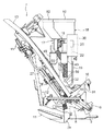
図1に示すように、前輪1及び後輪2で支持された機体の前部に、エンジン3及びミッションケース4を備えて、機体の中央部に運転部5を形成し、機体の後部に四連リンク式のリンク機構6を油圧シリンダ14により昇降駆動自在に連結して、リンク機構6に苗植付装置7を備えて乗用型田植機が構成されている。
[1]
As shown in FIG. 1, an engine 3 and a transmission case 4 are provided at the front of the aircraft supported by the
図1,2,4に示すように、苗植付装置7は8条植型式に構成されており、4個の伝動ケース8、伝動ケース8の左右両側に回転駆動自在に支持された回転ケース9、回転ケース9の両端に備えられた一対の植付アーム10、5個の接地フロート11、8条分の苗のせ面13aを備えた苗のせ台13、苗のせ台13の苗のせ面13aに備えられたベルト式の縦送り機構12等により構成されている。
As shown in FIGS. 1, 2, and 4, the
これにより、図1,2,4に示すように、苗のせ台13が左右に往復横送り駆動されるのに伴って、回転ケース9が回転駆動され、苗のせ台13(苗のせ面13a)の苗を植付アーム10が苗のせ台13(苗のせ面13a)の下部から交互に取り出して田面に植え付けるのであり、苗のせ台13が往復横送り駆動の右及び左端部に達すると、縦送り機構12により苗のせ台13(苗のせ面13a)の苗が下方に送られる。
Thereby, as shown in FIGS. 1, 2, and 4, the
図1及び図2に示すように、運転部5に備えられた運転座席23の後側に、2条に対応した4個の繰り出し部24が取り付けられ、透明樹脂製で肥料を貯留するホッパー25が4個の繰り出し部24に亘り取り付けられており、繰り出し部24に搬送風を供給するブロア26が備えられている。植付アーム10によって植え付けられた苗の横側に溝を形成しながら肥料を田面に送り込んでいく作溝器28が8個用意されて、作溝器28が接地フロート11に取り付けられており、繰り出し部24と作溝器28とに亘って8本の可撓性のホース27が接続されている。
以上の構造により、前述のように苗が田面に植え付けられるのに伴って、ホッパー25の肥料が繰り出し部24から所定量ずつ繰り出され、ブロア26の搬送風によりホース27を通って作溝器28に供給され、作溝器28により田面に形成された溝に肥料が送り込まれる。
As shown in FIGS. 1 and 2, four feeding
With the above structure, as seedlings are planted on the rice field as described above, the fertilizer in the
[2]
次に、苗のせ台13について説明する。
図3及び図4に示すように、8条の苗のせ面13a及び隣接する苗のせ面13aの間の9個の仕切り部13bによって苗のせ台13が構成されており、右の6条の苗のせ面13aに対して、左の2条の苗のせ面13aが分離可能に構成されている。
[2]
Next, the
As shown in FIGS. 3 and 4, the
図2に示すように、苗のせ台13の裏面において、右の6条の苗のせ面13aと左の2条の苗のせ面13aとに亘って支持フレーム15が配置されており、支持フレーム15の右端部が右の6条の苗のせ面13aに揺動及びスライド自在に接続され、支持フレーム15の左端部が左の2条の苗のせ面13aに揺動自在に接続されている。右の6条の苗のせ面13aの左端部の下部に、支持部16が備えられている。
As shown in FIG. 2, a
図2,3,4に示す状態は、右の6条の苗のせ面13a及び左の2条の苗のせ面13aが左右方向に並んで連結された苗のせ台13の作業状態である。苗のせ台13を作業状態から折り畳み状態に設定する場合、苗のせ台13を往復横送り駆動の左端部に移動させた状態で、右の6条の苗のせ面13aから左の2条の苗のせ面13aを分離させて、右の6条の苗のせ面13aに対し、左の2条の苗のせ面13a及び支持フレーム15を左方に移動させ、図8及び図9に示すように、支持フレーム15を上方に揺動させて、左の2条の苗のせ面13aを持ち上げ、左の2条の苗のせ面13aの下部を支持部16に支持させて固定する。
The state shown in FIGS. 2, 3, and 4 is a working state of the seedling setting table 13 in which the right six seedling setting surfaces 13 a and the left two seedling setting surfaces 13 a are connected side by side in the left-right direction. When the
これにより、苗のせ台13の折り畳み状態において、図8及び図9に示すように、右の6条の苗のせ面13aの上方に左の2条の苗のせ面13aが位置し、右の6条の苗のせ面13aの左の1条と、左の2条の苗のせ面13aの右の1条とが平面視で重なる状態となって、作業状態の苗のせ台13の横幅よりも(図3及び図4参照)、折り畳み状態の苗のせ台13の横幅が狭いものとなっている。
As a result, in the folded state of the seedling raising table 13, the left two
[3]
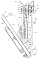
次に、右及び左の供給装置17,18を支持する右及び左の支持部材19,20について説明する。
図2,5,6に示すように、金属製の平板状の支持ブラケット32が5個用意されており、5個の支持ブラケット32は全て同じ形状に構成された同じものである。支持ブラケット32は側面視でへ字状に形成されて、上部に多数の取付孔32aが開口されており、下部が斜めのクランク状に折り曲げられて傾斜部32bが形成されている。図3,4,10,11に示すように、苗のせ台13(右の6条の苗のせ面13a)の右端部、右端部から2つ目及び4つ目の仕切り部13bの下部に、支持ブラケット32が固定されており、苗のせ台13(左の2条の苗のせ面13a)の左端部、左端部から1つ目の仕切り部13bの下部に、支持ブラケット32が固定されている。
[3]
Next, the right and left
As shown in FIGS. 2, 5, and 6, five metal plate-
図3,6,11に示すように、苗のせ台13(右の6条の苗のせ面13a)の右端部の支持ブラケット32の上部に、パイプ状の支持フレーム38が固定され、苗のせ台13(右の6条の苗のせ面13a)の右端部から2つ目の支持ブラケット32の下部に、支持フレーム36が固定されており、苗のせ台13(右の6条の苗のせ面13a)の右端部から4つ目の支持ブラケット32の上部及び下部に、パイプ状の支持フレーム38,33が固定されている。図3,5,10に示すように、苗のせ台13(左の2条の苗のせ面13a)の左端部の支持ブラケット32の下部に、パイプ状の支持フレーム33が固定されている。
As shown in FIGS. 3, 6, and 11, a pipe-
図3,4,6,11に示すように、断面コ字状の右の支持部材19が用意されており、右の支持部材19にパイプ状の支持部21が固定されている。苗のせ台13(右の6条の苗のせ面13a)の右端部及び右端部から4つ目の支持ブラケット32の支持フレーム38に、右の支持部材19の支持部21が取り付けられており、苗のせ台13(右の6条の苗のせ面13a)の右端部から2つ目の支持ブラケット32の支持フレーム36が、右の支持部材19に取り付けられている。
As shown in FIGS. 3, 4, 6, and 11, a
図3,4,5,10に示すように、断面コ字状の左の支持部材20が用意されており、左の支持部材20にパイプ状の支持部22が固定されている。苗のせ台13の作業状態において、苗のせ台13(左の2条の苗のせ面13a)の左端部の支持ブラケット32の支持フレーム33、並びに、苗のせ台13(右の6条の苗のせ面13)の右端部から4つ目の支持ブラケット32の支持フレーム33に、左の支持部材20の支持部22が取り付けられている。
As shown in FIGS. 3, 4, 5, and 10, a
図3,4,5,6,10,11に示すように、苗のせ台13(右の6条の苗のせ面13)において、3個の支持ブラケット32の取付孔32aに亘り右の案内ロッド43が取り付けられており、苗のせ台13(左の2条の苗のせ面13a)において、2個の支持ブラケット32の取付孔32aに亘り左の案内ロッド43が取り付けられている。この場合、支持ブラケット32の取付孔32aを変更することにより、右及び左の案内ロッド43の位置を上下に変更することができる。左の案内ロッド43の右端部に接続部43aが備えられており(図3,4,10参照)、右の案内ロッド43の左端部が左の案内ロッド43の接続部43aに接続及び取り外し自在に構成されている。
As shown in FIGS. 3, 4, 5, 6, 10, and 11, the right guide rod extends over the attachment holes 32 a of the three
図3,4,5,6に示すように、苗のせ台13の作業状態において、右の支持部材19が平面視で前側に位置し、左の支持部材20が平面視で後側に位置しおり、右及び左の支持部材19,20が側面視で同じ高さに位置している。右の支持部材19の左端部が左の支持部材20の右端部の位置よりも左方に位置し、左の支持部材20の右端部が右の支持部材19の左端部の位置よりも右方に位置している。
As shown in FIGS. 3, 4, 5, and 6, in the working state of the
[4]
次に、右及び左の供給装置17,18、右及び左の駆動機構29,30について説明する。
図3及び図4に示すように、右の支持部材19の右端部に右の駆動機構29が備えられており、左の支持部材20の左端部に左の駆動機構30が備えられている。図7に示すように、右及び左の駆動機構29,30に駆動スプロケット45及び従動スプロケット46が回転自在に支持されて、駆動スプロケット45を正逆に回転駆動するモータ49が備えられている。右の支持部材19の左端部(左の支持部材20の右端部)に従動スプロケット50が回転自在に支持されており、駆動スプロケット45及び従動スプロケット46,50に亘ってチェーン51が巻回されて、チェーン51が右及び左の支持部材19,20の内部に配置されている。
[4]
Next, the right and
As shown in FIGS. 3 and 4, a
図5,6,7に示すように、右及び左の供給装置17,18は薬剤(殺虫剤や殺菌剤等)又は肥料を貯留するホッパー52、ホッパー52の下部に連結された繰り出し部55、繰り出し部55の下部に連結された供給ホース56等を備えて構成されている。断面コ字状の案内シュー57がホッパー52の下部に固定されて、案内シュー57が右及び左の支持部材19,20の上部に移動自在に乗せられており、繰り出し部55に備えられたローラー58が右及び左の支持部材19,20に当て付けられている。繰り出し部55の内部に繰り出しローラー59が回転自在に支持され、繰り出しローラー59の支持軸59aが繰り出し部55から突出して右及び左の支持部材19,20の内部に入り込んでおり、繰り出しローラー59の支持軸59aに固定されたスプロケット60がチェーン51に咬合している。繰り出し部55に咬合部61が固定されて右及び左の支持部材19,20の内部に入り込んでおり、咬合部61がチェーン51に咬合している。
As shown in FIGS. 5, 6, and 7, the right and
図5,6,7に示すように、右及び左の供給装置17,18において、芯金部材62が供給ホース56の内部に備えられて、芯金部材62により供給ホース56の姿勢が設定されており、芯金部材62は金属製で細長い平板状である。図2,3,6に示すように、右の供給装置17において、供給ホース56が正面視で右の駆動機構29側に少し折り曲げられており、側面視で後側に折り曲げられている。図2,3,5に示すように、左の供給装置18において、供給ホース56が正面視で左の駆動機構30側に少し折り曲げられており、側面視で前側に折り曲げられている。これにより、図2,5,6に示すように、右及び左の供給装置17,18において、供給ホース56の下端部の供給口56aが側面視で同じ位置となっており、供給ホース56の供給口56aが右及び左の案内ロッド43の後側に位置している。
As shown in FIGS. 5, 6, and 7, in the right and
以上の構造により、図3,4,7に示すように、モータ49により駆動スプロケット45及びチェーン51が正逆に回転駆動されて、右の供給装置17が右の支持部材19の右及び左端部に亘って往復駆動されるのであり、左の供給装置18が左の支持部材20の右及び左端部に亘って往復駆動される。この場合、右の供給装置17が右の支持部材19の右端部に位置していると、左の供給装置18が左の支持部材20の右端部に位置し、右の供給装置17が右の支持部材19の左端部に位置していると、左の供給装置18が左の支持部材20の左端部に位置するように、右及び左の供給装置17,18が同時に同じ方向に往復駆動される。
With the above structure, as shown in FIGS. 3, 4, and 7, the
前述のように右及び左の供給装置17,18が往復駆動されると、図5,6,7に示すように、チェーン51によりスプロケット60が回転駆動され、繰り出しローラー59が回転駆動されて、ホッパー52に貯留された薬剤(殺虫剤や殺菌剤等)又は肥料が、繰り出しローラー59により所定量ずつ繰り出されて供給ホース56の供給口56aから下方に落下する。これにより、図3及び図4に示すように、苗のせ台13(右の4条の苗のせ面13a)に載置された苗に、右の供給装置17から薬剤(殺虫剤や殺菌剤等)又は肥料が供給されるのであり、苗のせ台13(左の4条の苗のせ面13a)に載置された苗に、左の供給装置18から薬剤(殺虫剤や殺菌剤等)又は肥料が供給される。
When the right and
この場合、図5及び図6に示すように、苗のせ台13に載置された苗が、右及び左の案内ロッド43により少し前方に倒されており、この倒された部分に右及び左の供給装置17,18から薬剤(殺虫剤や殺菌剤等)又は肥料が供給される。前述のように右及び左の供給装置17,18が往復駆動されると、仕切り部13b(支持ブラケット32)にも、薬剤(殺虫剤や殺菌剤等)又は肥料が供給されることがある。この場合、図3,5,6に示すように、支持ブラケット32の傾斜部32bにより、薬剤(殺虫剤や殺菌剤等)又は肥料が隣の苗のせ面13aの苗に案内される)。
In this case, as shown in FIGS. 5 and 6, the seedling placed on the seedling table 13 is tilted slightly forward by the right and
[5]
次に、前項[2]に記載のように苗のせ台13を作業状態から折り畳み状態に設定する場合について説明する。
図2及び図4に示すように、苗植付装置7の右端部及び右端部から2つ目の伝動ケース8に、パイプ状の取付部31が固定されている。これにより、苗のせ台13を作業状態から折り畳み状態に設定する場合、苗のせ台13を往復横送り駆動の左端部に移動させた状態で、先ず図8及び図9に示すように、左の支持部材20(左の供給装置18及び左の駆動機構30)の支持部22を、支持ブラケット32の支持フレーム33から取り外して、左の支持部材20(左の供給装置18及び左の駆動機構30)の支持部22を、取付部31に取り付ける。
[5]
Next, the case where the
As shown in FIGS. 2 and 4, a pipe-shaped
これにより、図8及び図9に示すように、左の支持部材20(左の供給装置18及び左の駆動機構30)が、右の支持部材19(右の供給装置17及び右の駆動機構29)の後側で下側に位置して、伝動ケース8に支持される状態となる。左の支持部材20(左の供給装置18及び左の駆動機構30)が伝動ケース8に支持された状態で、左の支持部材20(左の供給装置18及び左の駆動機構30)が、接地フロート11の後端よりも前側に位置している。
As a result, as shown in FIGS. 8 and 9, the left support member 20 (the
次に前項[2]に記載、図8及び図9に示すように、右の6条の苗のせ面13aから左の2条の苗のせ面13aを分離させて、右の6条の苗のせ面13aに対し、左の2条の苗のせ面13a及び支持フレーム15を左方に移動させ、支持フレーム15を上方に揺動させて、左の2条の苗のせ面13aを持ち上げ、左の2条の苗のせ面13aの下部を支持部16に支持させて固定する(苗のせ台13の折り畳み状態)。
この場合、右及び左の支持部材19,10(右及び左の供給装置17,18、右及び左の駆動機構29,30)の左隣に、左の2条の苗のせ面13aが位置する状態となり、左の2条の苗のせ面13aの後部(下部)が、接地フロート11の後端の上方に位置している。
Next, as shown in the preceding item [2] and shown in FIGS. 8 and 9, the left two
In this case, the left two
[発明の実施の第1別形態]
前述の[発明の実施の形態]において、左の2条の苗のせ面13aを右の6条の苗のせ面13aの上方に位置させることにより苗のせ台13の折り畳み状態を得るのではなく、左の2条の苗のせ面13aを上下反転させて右の6条の苗のせ面13aの上方に位置させることにより、苗のせ台13の折り畳み状態を得るように構成したり、右の6条の苗のせ面13aとの接続点を支点として、左の2条の苗のせ面13aを上方(又は下方)に折り曲げて、苗のせ台13の折り畳み状態を得るように構成してもよい。この場合、左の1条の苗のせ面13a又は左の3条の苗のせ面13aを、前述のような折り畳み状態に設定するように構成してもよい。
[First Alternative Embodiment of the Invention]
In the above-mentioned [Embodiment of the invention], instead of obtaining the folded state of the
[発明の実施の第2別形態]
前述の[発明の実施の形態]に対し、右の2条の苗のせ面13a(右の1条又は3条の苗のせ面13a)を、前述の[発明の実施の第1別形態]のような折り畳み状態に設定するように構成してもよい。このように構成すると、図3及び図4において、左の支持部材20が平面視で前側に位置し、右の支持部材19が平面視で後側に位置するように構成して、苗植付装置7の左端部及び左端部から2つ目の伝動ケース8に、パイプ状の取付部31を固定する。
本発明は8条の苗のせ台13(8条植型式の苗植付装置7)ばかりではなく、10条の苗のせ台13(10条植型式の苗植付装置7)にも適用できる。
[Second Embodiment of the Invention]
In contrast to the above-mentioned [Embodiment of the invention], the right two-
The present invention can be applied not only to the 8-row seedling setting stand 13 (8-row planting type seedling planting device 7) but also to the 10-row seedling setting table 13 (10-row planting type seedling planting device 7).
8 伝動ケース
10 植付アーム
11 接地フロート
13 苗のせ台
13a 苗のせ面
13b 仕切り部
17 右の供給装置
18 左の供給装置
19 右の支持部材
20 左の支持部材
29 右の駆動機構
30 左の駆動機構
32 支持ブラケット
DESCRIPTION OF
Claims (6)
右の所定数の前記苗のせ面の上側に亘って配置されるように前記苗のせ台に支持された右の支持部材と、前記右の支持部材に沿って往復移動自在に備えられた右の供給装置と、前記右の支持部材に備えられて前記右の供給装置を右の支持部材に沿って往復駆動する右の駆動機構とを備え、
左の所定数の前記苗のせ面の上側に亘って配置されるように前記苗のせ台に支持された左の支持部材と、前記左の支持部材に沿って往復移動自在に備えられた左の供給装置と、前記左の支持部材に備えられて前記左の供給装置を左の支持部材に沿って往復駆動する左の駆動機構とを備えて、
前記右及び左の供給装置が右及び左の支持部材に沿って往復移動しながら、右及び左の所定数の苗のせ面に載置された苗に上方から薬剤又は肥料を供給するように構成すると共に、
前記苗のせ台の右又は左側部分の位置を変更可能に構成して、前記苗のせ台の横幅を作業状態の苗のせ台の横幅よりも狭いものに設定可能に構成し、前記位置変更される側の右又は左の支持部材を苗のせ台から取り外し自在に構成してある乗用型田植機。 In a riding-type rice transplanter equipped with a seedling platform with a large number of seedling surfaces, a planting arm for taking out seedlings from the seedling surface and planting them on the rice field corresponding to each of the seedling surfaces,
A right support member supported by the seedling platform so as to be disposed over a predetermined number of right seedling placement surfaces, and a right support member that is reciprocally movable along the right support member. A supply device, and a right drive mechanism that is provided on the right support member and reciprocally drives the right supply device along the right support member,
A left support member supported by the seedling platform so as to be disposed over a predetermined number of left seedling placement surfaces, and a left support member that is reciprocally movable along the left support member. A supply device, and a left drive mechanism that is provided in the left support member and reciprocates the left supply device along the left support member,
The right and left supply devices are configured to supply medicine or fertilizer from above to seedlings placed on a predetermined number of seedling surfaces on the right and left while reciprocating along the right and left support members. As well as
The position of the right or left part of the seedling platform is configured to be changeable, the lateral width of the seedling platform is configured to be smaller than the lateral width of the seedling platform in the working state, and the position is changed. Riding type rice transplanter in which the right or left support member on the side is configured to be removable from the seedling bed.
前記位置変更される側の右又は左の支持部材が接地フロートの後端よりも前側に位置するように構成してある請求項2に記載の乗用型田植機。 In the state where the right or left support member on the side whose position is to be changed is removed from the seedling table and attached to the rear side of the right or left support member on the side whose position is not changed,
The riding type rice transplanter according to claim 2, wherein the right or left support member on the side where the position is changed is configured to be positioned in front of a rear end of the grounding float.
Priority Applications (1)
| Application Number | Priority Date | Filing Date | Title |
|---|---|---|---|
| JP2003332228A JP4266760B2 (en) | 2003-09-24 | 2003-09-24 | Ride type rice transplanter |
Applications Claiming Priority (1)
| Application Number | Priority Date | Filing Date | Title |
|---|---|---|---|
| JP2003332228A JP4266760B2 (en) | 2003-09-24 | 2003-09-24 | Ride type rice transplanter |
Publications (2)
| Publication Number | Publication Date |
|---|---|
| JP2005095053A JP2005095053A (en) | 2005-04-14 |
| JP4266760B2 true JP4266760B2 (en) | 2009-05-20 |
Family
ID=34460640
Family Applications (1)
| Application Number | Title | Priority Date | Filing Date |
|---|---|---|---|
| JP2003332228A Expired - Fee Related JP4266760B2 (en) | 2003-09-24 | 2003-09-24 | Ride type rice transplanter |
Country Status (1)
| Country | Link |
|---|---|
| JP (1) | JP4266760B2 (en) |
Families Citing this family (2)
| Publication number | Priority date | Publication date | Assignee | Title |
|---|---|---|---|---|
| JP5040592B2 (en) * | 2007-10-30 | 2012-10-03 | 井関農機株式会社 | Seedling transplanter |
| JP6458555B2 (en) * | 2015-02-26 | 2019-01-30 | 井関農機株式会社 | Seedling transplanter |
-
2003
- 2003-09-24 JP JP2003332228A patent/JP4266760B2/en not_active Expired - Fee Related
Also Published As
| Publication number | Publication date |
|---|---|
| JP2005095053A (en) | 2005-04-14 |
Similar Documents
| Publication | Publication Date | Title |
|---|---|---|
| JP2011160814A (en) | Seedling transplanter | |
| JP2010110264A (en) | Transplanting part of rice transplanter | |
| JP4266760B2 (en) | Ride type rice transplanter | |
| JP4909011B2 (en) | Rice transplanter | |
| JP3966843B2 (en) | Ride type rice transplanter | |
| JP4843849B2 (en) | Seedling planting machine | |
| WO2018135071A1 (en) | Rice transplanter | |
| JP5024442B2 (en) | Seedling transplanter | |
| JP5464254B2 (en) | Direct seeding machine | |
| JPS6124020Y2 (en) | ||
| WO2018074184A1 (en) | Rice transplanter | |
| JP5088723B2 (en) | Seedling planting machine | |
| JP3870077B2 (en) | Sweet potato seedling transplanter | |
| JP4016480B2 (en) | Seedling placement device | |
| JP2011050264A (en) | Seedling transplanter | |
| JP4009736B2 (en) | Seedling transplanter | |
| JP5678811B2 (en) | Seedling transplanter | |
| JP6830338B2 (en) | Rice transplanter | |
| JP2861802B2 (en) | Seedling box arrangement machine | |
| JP6967919B2 (en) | Seedling planting device | |
| JP3586982B2 (en) | Seedling plant | |
| JP3353776B2 (en) | Seedling box arrangement machine | |
| JP3846030B2 (en) | Seedling planting machine | |
| JP2018064524A (en) | Rice transplanter | |
| JP4360042B2 (en) | Odd-row planting seedling transplanter |
Legal Events
| Date | Code | Title | Description |
|---|---|---|---|
| A621 | Written request for application examination |
Free format text: JAPANESE INTERMEDIATE CODE: A621 Effective date: 20060921 |
|
| A977 | Report on retrieval |
Free format text: JAPANESE INTERMEDIATE CODE: A971007 Effective date: 20081226 |
|
| TRDD | Decision of grant or rejection written | ||
| A01 | Written decision to grant a patent or to grant a registration (utility model) |
Free format text: JAPANESE INTERMEDIATE CODE: A01 Effective date: 20090205 |
|
| A01 | Written decision to grant a patent or to grant a registration (utility model) |
Free format text: JAPANESE INTERMEDIATE CODE: A01 |
|
| A61 | First payment of annual fees (during grant procedure) |
Free format text: JAPANESE INTERMEDIATE CODE: A61 Effective date: 20090217 |
|
| R150 | Certificate of patent or registration of utility model |
Ref document number: 4266760 Country of ref document: JP Free format text: JAPANESE INTERMEDIATE CODE: R150 Free format text: JAPANESE INTERMEDIATE CODE: R150 |
|
| FPAY | Renewal fee payment (event date is renewal date of database) |
Free format text: PAYMENT UNTIL: 20120227 Year of fee payment: 3 |
|
| FPAY | Renewal fee payment (event date is renewal date of database) |
Free format text: PAYMENT UNTIL: 20130227 Year of fee payment: 4 |
|
| FPAY | Renewal fee payment (event date is renewal date of database) |
Free format text: PAYMENT UNTIL: 20140227 Year of fee payment: 5 |
|
| LAPS | Cancellation because of no payment of annual fees |