JP4264382B2 - Automatic exposure control method for photographed image and automatic exposure control apparatus using the method - Google Patents
Automatic exposure control method for photographed image and automatic exposure control apparatus using the method Download PDFInfo
- Publication number
- JP4264382B2 JP4264382B2 JP2004136620A JP2004136620A JP4264382B2 JP 4264382 B2 JP4264382 B2 JP 4264382B2 JP 2004136620 A JP2004136620 A JP 2004136620A JP 2004136620 A JP2004136620 A JP 2004136620A JP 4264382 B2 JP4264382 B2 JP 4264382B2
- Authority
- JP
- Japan
- Prior art keywords
- ray
- dark current
- pixel
- imaging
- ray imaging
- Prior art date
- Legal status (The legal status is an assumption and is not a legal conclusion. Google has not performed a legal analysis and makes no representation as to the accuracy of the status listed.)
- Expired - Fee Related
Links
Images


Classifications
-
- A—HUMAN NECESSITIES
- A61—MEDICAL OR VETERINARY SCIENCE; HYGIENE
- A61B—DIAGNOSIS; SURGERY; IDENTIFICATION
- A61B6/00—Apparatus or devices for radiation diagnosis; Apparatus or devices for radiation diagnosis combined with radiation therapy equipment
- A61B6/50—Apparatus or devices for radiation diagnosis; Apparatus or devices for radiation diagnosis combined with radiation therapy equipment specially adapted for specific body parts; specially adapted for specific clinical applications
- A61B6/51—Apparatus or devices for radiation diagnosis; Apparatus or devices for radiation diagnosis combined with radiation therapy equipment specially adapted for specific body parts; specially adapted for specific clinical applications for dentistry
-
- A—HUMAN NECESSITIES
- A61—MEDICAL OR VETERINARY SCIENCE; HYGIENE
- A61B—DIAGNOSIS; SURGERY; IDENTIFICATION
- A61B6/00—Apparatus or devices for radiation diagnosis; Apparatus or devices for radiation diagnosis combined with radiation therapy equipment
- A61B6/54—Control of apparatus or devices for radiation diagnosis
- A61B6/542—Control of apparatus or devices for radiation diagnosis involving control of exposure
-
- A—HUMAN NECESSITIES
- A61—MEDICAL OR VETERINARY SCIENCE; HYGIENE
- A61B—DIAGNOSIS; SURGERY; IDENTIFICATION
- A61B6/00—Apparatus or devices for radiation diagnosis; Apparatus or devices for radiation diagnosis combined with radiation therapy equipment
- A61B6/54—Control of apparatus or devices for radiation diagnosis
- A61B6/548—Remote control of the apparatus or devices
-
- H—ELECTRICITY
- H04—ELECTRIC COMMUNICATION TECHNIQUE
- H04N—PICTORIAL COMMUNICATION, e.g. TELEVISION
- H04N23/00—Cameras or camera modules comprising electronic image sensors; Control thereof
- H04N23/30—Cameras or camera modules comprising electronic image sensors; Control thereof for generating image signals from X-rays
-
- H—ELECTRICITY
- H04—ELECTRIC COMMUNICATION TECHNIQUE
- H04N—PICTORIAL COMMUNICATION, e.g. TELEVISION
- H04N25/00—Circuitry of solid-state image sensors [SSIS]; Control thereof
- H04N25/60—Noise processing, e.g. detecting, correcting, reducing or removing noise
- H04N25/63—Noise processing, e.g. detecting, correcting, reducing or removing noise applied to dark current
- H04N25/633—Noise processing, e.g. detecting, correcting, reducing or removing noise applied to dark current by using optical black pixels
-
- H—ELECTRICITY
- H04—ELECTRIC COMMUNICATION TECHNIQUE
- H04N—PICTORIAL COMMUNICATION, e.g. TELEVISION
- H04N25/00—Circuitry of solid-state image sensors [SSIS]; Control thereof
- H04N25/70—SSIS architectures; Circuits associated therewith
- H04N25/71—Charge-coupled device [CCD] sensors; Charge-transfer registers specially adapted for CCD sensors
- H04N25/711—Time delay and integration [TDI] registers; TDI shift registers
Landscapes
- Health & Medical Sciences (AREA)
- Engineering & Computer Science (AREA)
- Life Sciences & Earth Sciences (AREA)
- Medical Informatics (AREA)
- Signal Processing (AREA)
- Multimedia (AREA)
- Heart & Thoracic Surgery (AREA)
- Animal Behavior & Ethology (AREA)
- Optics & Photonics (AREA)
- Pathology (AREA)
- Radiology & Medical Imaging (AREA)
- Biomedical Technology (AREA)
- Physics & Mathematics (AREA)
- Molecular Biology (AREA)
- Surgery (AREA)
- Nuclear Medicine, Radiotherapy & Molecular Imaging (AREA)
- General Health & Medical Sciences (AREA)
- Public Health (AREA)
- Veterinary Medicine (AREA)
- High Energy & Nuclear Physics (AREA)
- Biophysics (AREA)
- Dentistry (AREA)
- Oral & Maxillofacial Surgery (AREA)
- Apparatus For Radiation Diagnosis (AREA)
Description
本発明は、固体撮像素子を用いた画像撮影に好適に実施される自動露出制御方法と、その自動露出制御方法を用いた自動露出制御装置に関するものである。ここで固体撮像素子は、可視光を露光するもの、及びX線を露光するものを含む。 The present invention relates to an automatic exposure control method that is preferably implemented for image capturing using a solid-state imaging device, and an automatic exposure control device that uses the automatic exposure control method. Here, the solid-state imaging device includes one that exposes visible light and one that exposes X-rays.
X線撮影装置における露出制御については、次のような先行技術がある。
下記の特許文献1では、X線露光前又は画像走査後にX線変換用光導電体を帯電しその表面をX線露光しないで走査して暗放電像の画像値をX線像の画像値から差し引いてX線撮影することが開示されている。
また、特許文献2では、CCDセンサを用いてパノラマX線撮影する技術において、CCDセンサの露光部の信号から非露光部での暗電流成分の信号を対比して暗電流成分を補正する技術が開示されている。
さらに、特許文献3では、CCDセンサ等の固体撮像素子の基板の裏面にX線量をモニタするフォトダイオードが形成されたX線撮影装置が開示されており、撮影中の透過X線をリアルタイムにフォトダイオードで検出することによってX線の出力を制御している。
Regarding exposure control in an X-ray imaging apparatus, there are the following prior arts.
In the following
Further,
また、特許文献4では、X線撮像器に被写体を透過したX線量を検出する線量センサをCCDセンサと連接して設けた医療用X線撮影装置が開示されており、CCDセンサに入射するX線量を線量センサで事前に検出して、X線発生器に帰還制御している。
しかしながら、上記特許文献1では、セレンからなるX線変換用光導電体という特殊なX線撮像素子を使用しており、固体撮像素子のような高解像度で、処理スピードを速く出来なくてコストも高くなる欠点がある。更に、この方法では、全部のX線変換用光導電体について暗放電像の画像値をX線露光前又は露光後に光導電体を帯電させて導出し、X線像の同一像点の画像値から差し引く事による補正であるので、撮影時間などの撮影条件が暗放電像を求めた時と異なれば、うまく補正できなかった。さらに、X線発生器にフィードバック制御することを示唆するものではない。
また、上記特許文献2では、パノラマX線撮影装置におけるCCDセンサの非露光部での暗電流信号を用いて暗電流の補正をするものであるが、X線撮影と同時に暗電流補正を行っていないのでX線発生器へのフィードバック制御を行えるものではなかった。自動露出制御はリアルタイムで制御を行わねばならず、上記特許文献2の方法では、リアルタイムで信号処理できなかった。
さらに、上記特許文献3では、撮像中の透過X線を裏面側のフォトダイオードでリアルタイムで検出しているため、検出信号をX線源側にフィードバックしてX線量の安定化を図るにはループ全体の応答がかなり速くなければならず、現実にはかなり困難を伴う。また、特殊な構造のためコストが高くついてしまう欠点があった。
上記特許文献4では、CCDセンサに入射するX線量を事前に検出して、X線発生器を帰還制御しているが、CCDセンサの出力中の暗電流成分には着目しておらず、従って、撮像中に走査速度を変える等の制御を行ったときに、CCDセンサの出力中の暗電流成分がそれに応じて変化しても、暗電流成分の変化は考慮されない。また、この構成も特殊な構造のためコストが高くついてしまう欠点があった。
However, in
In
Furthermore, in
In
本発明は、上述のような問題点を解決するため、暗電流成分を除去した画像が所定の濃度範囲に収まるように照射光の強度をフィードバック制御する自動露出制御方法およびその方法を用いた自動露出制御装置を提供することを目的とする。 In order to solve the above-described problems, the present invention provides an automatic exposure control method that feedback-controls the intensity of irradiation light so that an image from which dark current components are removed falls within a predetermined density range, and an automatic using the method. An object is to provide an exposure control device.
上記目的のため、請求項1では、X線発生器から被対象物にX線撮影のために照射されるX線の強度をフィードバック制御することで、固体撮像素子によって生成される画像が所定の濃度範囲内となるよう制御する自動露出制御方法であって、上記固体撮像素子が、上記X線を受けて発生した電荷を蓄積する画素生成部と、上記X線を受けないで暗電流成分を蓄積する暗電流測定部とを備え、上記固体撮像素子を非露光状態とした上記画素生成部の出力に基づく暗電流成分と上記暗電流測定部の出力に基づく暗電流成分とによる出力比を、上記画素生成部で注目する画素又は画素列について算出して予めメモリに記憶しておき、上記固体撮像素子がX線を受けているときに、上記暗電流測定部が出力した蓄積電荷信号に対して記憶された上記出力比を適用する演算により、上記画素生成部で注目する画素又は画素列に対する暗電流成分を算出し、上記画素生成部で注目する画素又は画素列の蓄積電荷信号から上記算出された暗電流成分を減算した値を算出することで、暗電流成分を除去した露出測定信号を取得し、該露出測定信号により上記X線の強度を決定することで、上記X線の強度をX線撮影時にフィードバック制御することを特徴とするX線撮影画像の自動露出制御方法を提案する。
For this purpose, in
尚、暗電流測定部と画素生成部における画素又は画素列との所定の露光時間に対する暗電流成分の出力比とは、固体撮像素子の電荷蓄積時間を所定時間としたときの、暗電流測定部から出力される蓄積電荷信号中の暗電流成分と、画素生成部における画素又は画素列から出力される蓄積電荷信号中の暗電流成分との出力強度の比を表している。
Note that the output ratio of the dark current component for a predetermined exposure time as the pixel or the pixel columns in the dark current sensing unit and a pixel generator, when the charge accumulation time of the solid-state imaging device with a predetermined time, the dark
請求項2では、請求項1において、上記メモリに記憶する上記出力比が、上記画素生成部の蓄積電荷信号の露光時間に対する出力変化の傾きと、上記暗電流測定部の蓄積電荷信号の露光時間に対する出力変化の傾きとの比であることを特徴とするX線撮影画像の自動露出制御方法を提案する。
ここで、暗電流測定部の蓄積電荷信号の露光時間に対する出力変化の傾きとは、暗電流測定部で注目する画素又は画素列から出力される蓄積電荷信号を電荷蓄積時間の1次関数で表したときの傾き(暗電流成分の露光時間に対する係数)である。
According to a second aspect of the present invention , in the first aspect , the output ratio stored in the memory includes an inclination of an output change with respect to an exposure time of the accumulated charge signal of the pixel generation unit and an exposure time of the accumulated charge signal of the dark current measuring unit. An automatic exposure control method for an X-ray image, which is characterized by the ratio of the change in output to the inclination of the image, is proposed.
Here, the gradient of the output change with respect to the exposure time of the accumulated charge signal of the dark current measuring unit is expressed by a linear function of the charge accumulation time, representing the accumulated charge signal output from the pixel or pixel column of interest in the dark current measuring unit. Is the slope (coefficient of dark current component with respect to exposure time).
請求項3では、請求項1又は請求項2のいずれかにおいて、上記X線の強度は、制御目標値に向けて、所定の遅延要素を加えるようにしてフィードバック制御することを特徴とするX線撮影画像の自動露出制御方法を提案する。
遅延要素を加えるには、コンデンサと抵抗によるローパスフィルタによるアナログ処理を用いてもよいし、過去の値に時間減衰率の重み付けをして、現在の値に足し合わせるデジタル処理を用いてもよい。
According to a third aspect of the present invention , in any one of the first and second aspects, the intensity of the X-ray is feedback-controlled by adding a predetermined delay element toward a control target value. We propose an automatic exposure control method for captured images.
In order to add a delay element, analog processing using a low-pass filter with a capacitor and a resistor may be used, or digital processing may be used in which a past value is weighted with a time decay rate and added to the current value.
請求項4では、請求項1〜3のいずれかにおいて、上記照射源をX線を照射するX線発生器とし、上記固体撮像素子が、該X線発生器からのX線を受けて可視光を生成する構成を有することを特徴とするX線撮影画像の自動露出制御方法を提案する。すなわち、請求項1の自動露出制御の対象を医療用デジタルX線撮影装置に限定している。
According to a fourth aspect of the present invention , in any one of the first to third aspects, the irradiation source is an X-ray generator that emits X-rays, and the solid-state imaging device receives X-rays from the X-ray generator and receives visible light. This invention proposes an automatic exposure control method for an X-ray image, characterized in that it has a configuration for generating image data. That is, the subject of automatic exposure control of
請求項5では、請求項4において、上記撮影は、パノラマX線撮影、セファロX線撮影、リニアスキャンX線撮影、デンタルX線撮影又はCT撮影のいずれかを行うことを特徴とするX線撮影画像の自動露出制御方法を提案している。
According to
請求項6では、請求項4又は5において、X線強度をフィードバック制御するにあたり、X線走査速度、X線管電流、X線管電圧のうちの少なくとも1つ以上を制御することを特徴とする撮影画像の自動露出制御方法を提案する。 A sixth aspect of the present invention is the method according to the fourth or fifth aspect, wherein at least one of the X-ray scanning speed, the X-ray tube current, and the X-ray tube voltage is controlled in feedback control of the X-ray intensity. We propose an automatic exposure control method for captured images.
請求項7では、X線発生器からX線撮影のために照射されるX線の強度をフィードバック制御して所定の濃度範囲内となるX線撮影画像を取得する医療用デジタルX線撮影装置における自動露出制御装置であって、上記X線を受けて発生した電荷を蓄積する画素生成部と、X線を受けないで暗電流成分を蓄積する暗電流測定部とを備えた固体撮像素子と、上記画素生成部で注目する画素又は画素列について算出された、上記固体撮像素子を非露光状態とした上記画素生成部の出力に基づく暗電流成分と上記暗電流測定部の出力に基づく暗電流成分とによる出力比を、予め記憶させたメモリと、上記暗電流測定部が出力した蓄積電荷信号に対して記憶された上記出力比を適用した演算により、上記画素生成部で注目する画素又は画素列に対する撮像時における暗電流成分を算出し、当該撮像時における暗電流成分を上記画素生成部で注目する画素又は画素列の蓄積電荷信号から減算した値を算出することで、暗電流成分を除去した露出測定信号を取得し、該露出測定信号により上記X線の強度を決定することで、上記X線の強度をX線撮影時にフィードバック制御する制御手段とを備えたことを特徴とするX線撮影画像の自動露出制御装置を提案する。
すなわち、X線を受けて可視光を生成し光電変換して電荷を蓄積する画素生成部と、X線を受けないで暗電流成分を蓄積する暗電流測定部とを備えた固体撮像素子と、上記画素生成部から取り出されたで注目する画素又は画素列の蓄積電荷信号から上記暗電流測定部から取り出される暗電流成分を除去した画像が所定の濃度範囲に収まるようにX線強度をフィードバック制御する制御演算部とを備えている。
According to a seventh aspect of the present invention, there is provided a medical digital X-ray imaging apparatus that obtains an X-ray imaging image within a predetermined density range by feedback-controlling the intensity of X-rays irradiated for X-ray imaging from an X-ray generator. A solid-state imaging device that is an automatic exposure control device and includes a pixel generation unit that accumulates charges generated by receiving the X-rays, and a dark current measurement unit that accumulates dark current components without receiving X-rays; The dark current component based on the output of the pixel generation unit and the dark current component based on the output of the dark current measurement unit, which are calculated for the pixel or pixel column of interest in the pixel generation unit and the solid-state imaging device is in an unexposed state The pixel or pixel row to be noticed by the pixel generation unit is calculated by applying a memory in which the output ratio is stored in advance and the output ratio stored to the accumulated charge signal output from the dark current measurement unit. Against Calculating a dark current component at the image, the dark current component at the time of the imaging by calculating a value obtained by subtracting from the accumulated charge signals of the pixels or pixel column of interest in the pixel generator, exposure to remove the dark current component X-ray imaging image comprising: a control unit that obtains a measurement signal and determines the X-ray intensity based on the exposure measurement signal, thereby feedback-controlling the X-ray intensity during X-ray imaging An automatic exposure control device is proposed.
That is, a solid-state imaging device including a pixel generation unit that generates visible light by receiving X-rays, photoelectrically accumulates charges, and a dark current measurement unit that accumulates dark current components without receiving X-rays; Feedback control of the X-ray intensity so that an image obtained by removing the dark current component extracted from the dark current measurement unit from the accumulated charge signal of the pixel or pixel column of interest extracted from the pixel generation unit is within a predetermined density range. A control operation unit.
そして、演算制御部は、上記暗電流成分を除去するにあたり、上記画素生成部から取り出される暗電流成分に基づいて、暗電流測定部の特定の画素又は列の所定の露光時間に対する出力変化の傾きを予め記憶し、画素生成部の特定の画素又は列の所定の露光時間に対する出力変化の傾きとの比を求め、この傾きの比を基に演算し暗電流成分を除去した画像が所定の濃度範囲に収まるようにX線強度をフィードバック制御する。 Then, when removing the dark current component , the arithmetic control unit, based on the dark current component extracted from the pixel generation unit, the slope of the output change with respect to a predetermined exposure time of a specific pixel or column of the dark current measurement unit Is stored in advance, the ratio of the output change with respect to a predetermined exposure time of a specific pixel or column of the pixel generation unit is obtained, and an image obtained by calculating the ratio of the inclination and removing the dark current component has a predetermined density The X-ray intensity is feedback controlled so as to be within the range.
請求項8では、請求項7において、X線強度をフィードバック制御するにあたり、X線走査速度、X線管電流、X線管電圧のうちの少なくとも1つ以上を制御することを特徴とする撮影画像の自動露出制御装置を提案する。 According to an eighth aspect of the present invention, in the seventh aspect , when the X-ray intensity is feedback controlled, at least one of the X-ray scanning speed, the X-ray tube current, and the X-ray tube voltage is controlled. An automatic exposure control device is proposed.
請求項1〜6で提案した本発明の自動露出制御方法によれば、X線発生器から被対象物にX線を照射してX線画像を生成する画像生成装置に適用すれば、画素生成部から取り出された特定の画素又は列の蓄積電荷信号から、暗電流測定部から取り出される暗電流成分を除去した画像が所定の濃度範囲に収まるようにX線の強度をフィードバック制御するので、暗電流成分を除去した最終的な画像に対する露出制御となって、良好な露出制御結果が得られる。
According to the automatic exposure control method of the present invention proposed in
そして、本発明方法によれば、画素生成部の特定の画素又は列の蓄積電荷信号の露光時間に対する出力変化の傾きと、暗電流測定部での画素又は少なくとも1列の蓄積電荷信号の露光時間に対する出力変化の傾きとの比を求めているので、補正処理での演算が簡単になる。
また、請求項3で提案した本発明方法によれば、照射光の強度は、制御目標値に向けて、所定の遅延要素を加えるようにしてフィードバック制御されているので、得られた画像ではフィードバック制御に起因する縞状のノイズが目立たない。
According to the method of the present invention , the slope of the output change with respect to the exposure time of the accumulated charge signal of the specific pixel or column of the pixel generation unit, and the exposure time of the accumulated charge signal of the pixel or at least one column in the dark current measurement unit Since the ratio with the slope of the output change with respect to is calculated, the calculation in the correction process is simplified.
Further, according to the method of the present invention proposed in
特に請求項5で提案した本発明方法によれば、パノラマX線撮影、セファロX線撮影、リニアスキャンX線撮影、デンタルX線撮影又はCT撮影において、自動露出制御を行える。
In particular, according to the method of the present invention proposed in
請求項4及び請求項5で提案した自動露出制御方法は、請求項1の自動露出制御方法を医療用デジタルX線撮影装置に適用するもので、請求項1と同様の効果をそこで発揮する。
The automatic exposure control method proposed in
請求項6では、X線走査速度、X線管電流、X線管電圧のうちの少なくとも1つ以上をフィードバック制御の対象としているので、撮影条件に応じて最適な制御対象を選択することができるとともに、これらを組み合わせれば、望ましい画質の自動露出制御が行える。
請求項7及び請求項8による医療用デジタルX線撮影装置では、それぞれ、請求項1〜6のいずれかの自動露出制御方法を適用しているので、それらと同様の効果が期待できる。
According to the sixth aspect , since at least one of the X-ray scanning speed, the X-ray tube current, and the X-ray tube voltage is a target of feedback control, an optimal control target can be selected according to imaging conditions. In addition, by combining these, automatic exposure control with desirable image quality can be performed.
In the digital X-ray apparatus for medical use according to
以下では、撮影画像の自動露出制御方法を説明し、ついで、その方法を適用した具体的な医療用デジタルX線撮影装置について説明する。 Below, the automatic exposure control method of a picked-up image is demonstrated, and then the specific medical digital X-ray imaging apparatus to which the method is applied is demonstrated.
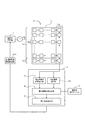
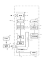
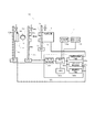
図1は本発明の自動露出制御装置の基本構成を示している。
自動露出制御装置A1は、撮影光照射源7から照射され、撮影対象Hを透過した光を露光するCCDセンサ等の固体撮像素子1aと、制御演算手段2、照射源制御手段20dとを有している。ここに、固体撮像素子1aは、TDI(時間遅延積分)クロックから駆動クロックを生成する後述の図10、図11で図示するような撮像素子駆動回路11dによる駆動クロックによって駆動されるようになっており、画素生成部1aaと、暗電流測定部1abと、蓄積電荷転送部1acとに区分された構成になっている。
FIG. 1 shows the basic configuration of the automatic exposure control apparatus of the present invention.
The automatic exposure control device A1 includes a solid-
画素生成部1aaは、高エネルギーの光(X線など)によって発生した電荷を蓄積して転送するCCDが列状に配置されている。暗電流測定部1abも、画素生成部1aaと同様のCCDが1列又は複数列に配置されているが、常に光を露光しないようにマスク(X線遮蔽)されている。また、蓄積電荷転送部1acには、画素生成部1aaや暗電流測定部1abの各列から出力される電荷を転送するためのCCDが列方向に配置されており、画素生成部1aaからの蓄積電荷信号と、暗電流測定部1abからの暗電流測定信号とが、逐次、所定のタイミングで右下の出口部から制御演算手段2に対して出力されるようになっている。 In the pixel generation unit 1aa, CCDs that store and transfer charges generated by high-energy light (such as X-rays) are arranged in a row. The dark current measuring unit 1ab also has the same CCD as the pixel generating unit 1aa arranged in one or more columns, but is always masked (X-ray shielded) so as not to expose light. In the accumulated charge transfer unit 1ac, CCDs for transferring charges output from the columns of the pixel generation unit 1aa and the dark current measurement unit 1ab are arranged in the column direction, and accumulation from the pixel generation unit 1aa is performed. The charge signal and the dark current measurement signal from the dark current measurement unit 1ab are sequentially output to the control calculation means 2 from the lower right exit part at a predetermined timing.
更に自動露出制御を行うために、画像生成部1aaには注目画素1agを設定している。注目画素1agは画素生成部1aaの任意の位置でよいが、撮影対象物の関心領域内であって撮影中に受光量があまり変化しない位置に設定することが望ましい。歯科用パノラマX線撮影装置の場合、上顎の少し上あたりが最も良い。この注目画素1agの蓄積電荷信号から暗電流成分を除去した露出測定信号に基づいて、本発明の自動露出制御が行われる。さらに露出測定部は1つの注目画素1agによる構成に限られず、注目画素1agが2以上の場合には、それらの平均値などを露出測定信号として採用する。 Further, in order to perform automatic exposure control, a target pixel 1ag is set in the image generation unit 1aa. The target pixel 1ag may be at an arbitrary position of the pixel generation unit 1aa, but is preferably set at a position within the region of interest of the object to be imaged so that the amount of received light does not change much during imaging. In the case of a dental panoramic X-ray imaging apparatus, the upper part of the upper jaw is best. Based on the exposure measurement signal obtained by removing the dark current component from the accumulated charge signal of the target pixel 1ag, the automatic exposure control of the present invention is performed. Furthermore, the exposure measurement unit is not limited to the configuration with one target pixel 1ag, and when the target pixel 1ag is 2 or more, the average value thereof is adopted as the exposure measurement signal.
制御演算手段2は、撮像時において画素生成部1aaより取り出された蓄積電荷信号の暗電流成分を除去する一方、X線照射制御回路20dをフィードバック制御するもので、電荷蓄積型イメージセンサ1から出力された蓄積電荷信号から所定のタイミングで暗電流測定信号を抽出するための暗電流測定信号抽出部2aと、同様にそこから所定のタイミングで、注目画素1agの蓄積電荷信号を取り出すための注目画素抽出部2dと、注目画素1agから出力された蓄積電荷信号毎に、暗電流補正テーブル3に記録されている、後述するパラメータを参照適用し、暗電流測定部1abから出力された暗電流測定信号に基づいて、注目画素1agから出力された蓄積電荷信号中の暗電流成分を予測算出して除去した露出制御信号を得る露出制御信号生成部2bと、その露出制御信号に基づいて、撮影光照射源7から照射させるべき撮影光の強度を算出して、X線照射制御回路20dをフィードバック制御するための信号を出力する照射強度算出部2fとを備えている。
The control calculation means 2 removes the dark current component of the accumulated charge signal taken out from the pixel generation unit 1aa at the time of imaging and feedback-controls the X-ray
暗電流補正テーブル3は、画素生成部1aaの各列の電荷を所定の転送経路、すなわち各列での横方向の転送経路と、更に蓄積電荷転送部1acでの縦方向の転送経路とに従って転送している間に生じる暗電流成分を、暗電流測定部1abで測定した暗電流測定信号に基づいて予測算出するためのパラメータを予め記憶している。 Dark current compensation table 3, thus the longitudinal direction of the transfer path of the charge of each column of pixel generator 1aa predetermined transfer path, i.e. the transverse transfer path for each column, with further accumulated charge transfer portion 1ac A parameter for predicting and calculating a dark current component generated during transfer based on a dark current measurement signal measured by the dark current measuring unit 1ab is stored in advance.
ここで、露出制御装置における自動露出制御の原理を説明する。
画像撮影時の温度がξのときに、固体撮像素子1aの画素生成部1aaと暗電流測定部1abとの各列(k=n・・・1,0)について、それぞれの全段で蓄積された電荷が蓄積電荷転送部1acを通じて転送され、暗電流測定信号Os(p0,ξ)を含んだ蓄積電荷信号Os(pk,ξ)として出力されるとすると、それらは次式(イ)によって表される。
Os(pn,ξ)=Osx(pn,ξ)+Dk(pn,ξ)+Of(pn)
Os(pn−1,ξ)=Osx(pn−1,ξ)+Dk(pn−1,ξ)+Of(pn−1)
|
Os(p1,ξ)=Osx(p1,ξ)+Dk(p1,ξ)+Of(p1)
Os(p0,ξ)=Dk(p0,ξ)+Of(p0) …(イ)
ただし、
Os :蓄積電荷信号
Osx :露光に基づく有効画素信号(蓄積電荷信号の露光による信号成分)
Dk :蓄積電荷信号の暗電流成分
Of :蓄積電荷信号のオフセット成分
p :列の位置
ξ :温度
一方、同様に固体撮像素子1aを遮蔽して露光させないときには、暗電流測定信号Os(p0,ξ)を含んだ蓄積電荷信号Os(pk,ξ)は式(ロ)で示される。
Os(pn,ξ)=Dk(pn,ξ)+Of(pn)
Os(pn−1,ξ)=Dk(pn−1,ξ)+Of(pn−1)
|
Os(p1,ξ)=Dk(p1,ξ)+Of(p1)
Os(p0,ξ)=Dk(p0,ξ)+Of(p0) …(ロ)
Here, the principle of automatic exposure control in the exposure control apparatus will be described.
When the temperature at the time of image capturing is ξ, each column (k = n..., 0) of the pixel generation unit 1aa and the dark current measurement unit 1ab of the solid-
Os (pn, ξ) = Osx (pn, ξ) + Dk (pn, ξ) + Of (pn)
Os (pn−1, ξ) = Osx (pn−1, ξ) + Dk (pn−1, ξ) + Of (pn−1)
|
Os (p1, ξ) = Osx (p1, ξ) + Dk (p1, ξ) + Of (p1)
Os (p0, ξ) = Dk (p0, ξ) + Of (p0) (B)
However,
Os: accumulated charge signal Osx: effective pixel signal based on exposure (signal component due to exposure of accumulated charge signal)
Dk: dark current component of accumulated charge signal Of: offset component of accumulated charge signal p: column position ξ: temperature On the other hand, when the solid-
Os (pn, ξ) = Dk (pn, ξ) + Of (pn)
Os (pn−1, ξ) = Dk (pn−1, ξ) + Of (pn−1)
|
Os (p1, ξ) = Dk (p1, ξ) + Of (p1)
Os (p0, ξ) = Dk (p0, ξ) + Of (p0) (B)
また、暗電流成分は、固体撮像素子1aの電荷蓄積時間Tにほぼ比例することが知られていることから、第k列の暗電流成分は次式(ハ)で求められる。
Dk(pk,ξ)=α(pk,ξ)・T …(ハ)
ただし、ここで
α :係数
T :蓄積時間
Further, since it is known that the dark current component is substantially proportional to the charge accumulation time T of the solid-
Dk (pk, ξ) = α (pk, ξ) · T (C)
Where α: Coefficient T: Accumulation time
上式(ハ)より(ロ)は一次関数ととらえられ、電荷蓄積時間Tを何通りか変化させて、蓄積電荷信号Os(pk,ξ)や暗電流測定信号Os(p0,ξ)の値を測定し、最小二乗法を用いれば最適なものになるが、簡易には、2通りの電荷蓄積時間Tについて、それぞれ値を測定し、その2点を通る直線により求められるものとしてもよい。
更に、ここで画素生成部1aaの第k列の暗電流成分Dk(pk,ξ)と、暗電流測定部1abの暗電流成分Dk(p0,ξ)との、所定の蓄積時間Tにおける出力比α2を求めると、次式(ニ)のようになる。次式(ニ)の右辺に示す比は、固体撮像素子1aを露光させないときの蓄積電荷信号Os(pk,ξ)のグラフと暗電流測定信号Os(p0,ξ)のグラフとの傾きの比に相当する。
α2(pk,ξ)=Dk(pk,ξ)/Dk(p0,ξ)
={α(pk,ξ)・T}/{α(p0,ξ)・T}
=α(pk,ξ)/α(p0,ξ) …(ニ)
ここで、出力比α(pk,ξ)が、場所pkに依存する部分と温度ξに分離できるとすれば、
α(pk,ξ)=α1(pk)・β(ξ)
であるから、出力比α2は温度ξに依存せずに次式(ホ)のようになる。
α2(pk)=α1(pk)/α1(p0) …(ホ) From the above equation (c), (b) is regarded as a linear function, and the values of the accumulated charge signal Os (pk, ξ) and the dark current measurement signal Os (p0, ξ) are changed by changing the charge accumulation time T in several ways. was measured, but become optimum by using the least squares method, the simple, the charge accumulation time T of the two types, each value was measured may be those obtained by a straight line passing through the two points.
Further, here, the output ratio of the dark current component Dk (pk, ξ) in the k-th column of the pixel generation unit 1aa and the dark current component Dk (p0, ξ) of the dark current measurement unit 1ab in a predetermined accumulation time T. When α2 is obtained, the following equation (d) is obtained. The ratio shown on the right side of the following equation (d) is the ratio of the slope between the graph of the accumulated charge signal Os (pk, ξ) and the graph of the dark current measurement signal Os (p0, ξ) when the solid-
α2 (pk, ξ) = Dk (pk, ξ) / Dk (p0, ξ)
= {Α (pk, ξ) · T} / {α (p0, ξ) · T}
= Α (pk, ξ) / α (p0, ξ) (D)
Here, if the output ratio α (pk, ξ) can be separated into a part depending on the location pk and the temperature ξ,
α (pk, ξ) = α1 (pk) · β (ξ)
Therefore, the output ratio α2 does not depend on the temperature ξ and is expressed by the following equation (e) .
α2 (pk) = α1 (pk) / α1 (p0) (e)
従って、式(イ)及び、式(ホ)から、撮影時の温度がξのとき、画素生成部1aaの各列(k=n・・・1)の露光に基づく有効画素信号Osx(pk,ξ)を、暗電流測定信号Os(p0,ξ)を用いて表すと、更に(ヘ)のようになる。
Osx(pk,ξ)=Os(pk,ξ)−Dk(pk,ξ)−Of(pk)
=Os(pk,ξ)−α2(pk)・Dk(p0,ξ)−Of(pk)
=Os(pk,ξ)−α2(pk)・{Os(p0,ξ)−Of(p0)}−Of(pk) …(ヘ)
Therefore, from the equations (A) and (E) , when the temperature at the time of shooting is ξ, the effective pixel signal Osx (pk, pk, p) based on the exposure of each column (k = n... 1) of the pixel generation unit 1aa. When ξ) is expressed using the dark current measurement signal Os (p0, ξ), it becomes as shown in (f) .
Osx (pk, ξ) = Os (pk, ξ) −Dk (pk, ξ) −Of (pk)
= Os (pk, ξ) −α2 (pk) · Dk (p0, ξ) −Of (pk)
= Os (pk, ξ) −α2 (pk) · {Os (p0, ξ) −Of (p0)} − Of (pk) (f)
よって式(ヘ)から理解されるように、撮影時において、注目画素1agの蓄積電荷信号Os(pg,ξ)を、式(ヘ)に従い、暗電流測定部1abの暗電流測定信号Os(p0,ξ)を用いて補正すれば、暗電流成分の除去された露出測定信号を得ることができる。
すなわち本発明では、自動露出制御を行うために、注目画素抽出部2dが、注目画素1agから出力された蓄積電荷信号Os(pg,ξ)を所定のタイミングで取り出し、露出制御信号生成部2bが、次の式に従って、上記の露出制御信号Xを算出する。
X=Os(pg,ξ)−α2(pg)・Os(p0,ξ) …(チ)
ただし、
X :露出制御信号
pg :注目画素1agの位置
ここで、Of(pg)は、定数なので式(チ)から除かれている。
そして、照射強度算出部2fが次の式に従って、照射させるべき撮影光の強度を算出して、X線照射制御回路20dをフィードバック制御することにより、自動露出制御がなされる。
I=−A・X+B …(リ)
ただし、
I :照射源制御手段に発生させるべき撮影光照射源の駆動電流
A、B:定数
なお、撮影光照射源の駆動電流を制御するのに替えて、駆動電圧を同様に制御してもよく、更に、駆動電流と駆動電圧との両方を制御してもよく、駆動電流の替わりに走査速度を制御するようにしてもよい。そして、駆動電流か走査速度かを制御する場合には、透過X線量が全体的に変化するので、得られるX線画像の明るさが変わるが、駆動電圧を制御する場合には、透過X線のエネルギー分布が変化するので、得られるX線画像のコントラストが変わる。
Therefore, as understood from the equation (f) , at the time of shooting, the accumulated charge signal Os (pg, ξ) of the target pixel 1ag is converted into the dark current measurement signal Os (p0 ) of the dark current measuring unit 1ab according to the equation (f). , Ξ) can be used to obtain an exposure measurement signal from which dark current components have been removed.
That is, in the present invention, in order to perform automatic exposure control, the target
X = Os (pg, ξ) −α2 (pg) · Os (p0, ξ) (h)
However,
X: Exposure control signal pg: Position of the target pixel 1ag Here, Of (pg) is a constant, and is excluded from the equation (H).
Then, the exposure
I = −A · X + B (Li)
However,
I: Driving current of the photographing light irradiation source to be generated by the irradiation source control means A, B: Constant Note that instead of controlling the driving current of the photographing light irradiation source, the driving voltage may be controlled similarly, Furthermore, both the drive current and the drive voltage may be controlled, or the scanning speed may be controlled instead of the drive current. When controlling the drive current or the scanning speed, the transmitted X-ray dose changes as a whole, so that the brightness of the obtained X-ray image changes. However, when controlling the drive voltage, the transmitted X-ray dose is changed. Since the energy distribution of the X-ray image changes, the contrast of the obtained X-ray image changes.
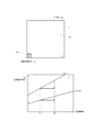
ここで、上記の自動露出制御の原理を、CCDセンサを用いた固体撮像素子1aによるX線パノラマ撮影に適用した場合と、MOSセンサを用いた固体撮像素子1aによる通常の透過X線撮影に適用した場合について、図2に従って更に説明する。
Here, the above-mentioned principle of automatic exposure control is applied to X-ray panoramic radiography using a solid-
図2Aは、CCDセンサを用いた固体撮像素子1aの各列から出力される蓄積電荷信号(一次元)を撮影時刻順に並べた歯科用等のパノラマX線撮影をする際の時間と電気信号の出力の関係図を示している。図において(i)は、画素生成部1aa中の特定画素、すなわち注目画素1agと暗電流測定部1abの位置とをそれぞれpgとp0で示し、(ii)は暗電流測定部1abからの暗電流測定信号(暗電流成分)Dk(p0)を示している。これは、工場出荷前に予めX線パノラマ撮影した際の暗電流測定部1abでの暗電流測定信号を示す。(iii)は実際の撮影時の注目画素1agからの蓄積電荷信号Os(pg)と、その中の暗電流成分Dk(pg)を示している。
(ii)、(iii)から理解されるように、被験者の臼歯部−前歯部−臼歯部とX線パノラマ撮影する場合、一般的に前歯部ではパノラマ撮影の走査速度を遅くしてX線量を増やすことによって、頸椎によるX線吸収を補っている。このためにその部分では暗電流成分Dk(pg)が走査速度に応じて増加している。しかし、絶対強度の変動にかかわらず、暗電流測定部1abと注目画素1agの暗電流成分との出力比はほぼ一定である。すなわち、図においては、出力比であるb/aが一定になっている。
従って、暗電流測定部1abと注目画素1agとの、所定の露光時間に対する暗電流成分の出力比を暗電流補正テーブル3に予め記憶しておけば、撮像時において注目画素1agより取り出された蓄積電荷信号Os(pg)に対してその出力比を適用して暗電流成分Dk(pg)を予測演算できる。従って、蓄積電荷信号Os(pg)から暗電流成分Dk(pg)を除去した露出測定信号を算出し、それに基づいて自動露出制御することが可能である。
FIG. 2A shows the time and electric signal when performing panoramic X-ray photography such as dental use in which accumulated charge signals (one-dimensional) output from each column of the solid-
As will be understood from (ii) and (iii), when X-ray panoramic imaging of the subject's molar part-anterior tooth part-molar part is performed, generally the scanning speed of panoramic imaging is slowed at the anterior tooth part to obtain an X-ray dose. By increasing, X-ray absorption by the cervical spine is compensated. For this reason, the dark current component Dk (pg) increases in accordance with the scanning speed in that portion. However, the output ratio between the dark current measurement unit 1ab and the dark current component of the target pixel 1ag is substantially constant regardless of the change in absolute intensity. That is, in the figure, the output ratio b / a is constant.
Therefore, if the output ratio of the dark current component between the dark current measuring unit 1ab and the target pixel 1ag with respect to a predetermined exposure time is stored in advance in the dark current correction table 3, the accumulation extracted from the target pixel 1ag at the time of imaging is stored. The dark current component Dk (pg) can be predicted by applying the output ratio to the charge signal Os (pg). Therefore, it is possible to calculate an exposure measurement signal obtained by removing the dark current component Dk (pg) from the accumulated charge signal Os (pg), and to perform automatic exposure control based on the calculated exposure measurement signal.
図2Bは、MOSセンサを用いた固体撮像素子1aから出力される蓄積電荷信号Os(pg)を画素eの位置に応じて二次元に並べた画像における特定の画素、すなわち注目画素1agの位置pgと暗電流測定部1abの位置p0とを示す図面(iv)と、及び注目画素1agの位置と暗電流測定部1abの位置p0のそれぞれの蓄積電荷信号Os(pg)及び暗電流測定信号Os(p0)と露光時間Tとの関係(v)を示すグラフである。
(v)のグラフから理解されるように、固体撮像素子1aを露光させないときの注目画素1agの蓄積電荷信号Os(pg)の露光時間Tに対する出力変化の傾きと、暗電流測定部1abでの画素又は少なくとも1列の暗電流測定信号Os(p0)の露光時間に対する出力変化の傾きとの比は、ほぼ一定の比例関係になっている。従って、その出力変化の傾きの比を画素生成部1aaの各画素または各列に対応させて暗電流補正テーブル3に予め記憶しておけば、撮像時において注目画素1agより取り出された蓄積電荷信号Os(pg)に対してその出力変化の傾きを適用して実際の撮影時間に応じて暗電流成分Dk(pg)を予測演算できる。従って、暗電流成分Dk(pg)を除去した露出測定信号を算出し、それに基づいて自動露出制御することが可能である。
FIG. 2B shows a specific pixel in an image in which the accumulated charge signal Os (p g ) output from the solid-
As can be understood from the graph of (v), the gradient of the output change with respect to the exposure time T of the accumulated charge signal Os (pg) of the pixel of interest 1ag when the solid-
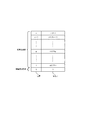
図3は、その暗電流補正テーブルの一例である。
図において、α2(pk=1…n)はそれぞれ、画素生成部1aaの各列(k=1…n)の暗電流測定信号に対する所定の露光時間における出力比α2を示している。このように各列に対して出力比を記憶しておけば、注目画素1agを画素生成部1aaの任意の位置に設定できる。
FIG. 3 is an example of the dark current correction table.
In the figure, α2 (pk = 1... N) indicates an output ratio α2 at a predetermined exposure time with respect to the dark current measurement signal of each column (k = 1... N) of the pixel generation unit 1aa. If the output ratio is stored for each column in this way, the target pixel 1ag can be set at an arbitrary position in the pixel generation unit 1aa.
更にここで、制御演算手段2による駆動電流Iに対するフィードバック制御の作用を図について定性的に説明する。
図4は、露出制御信号Xと駆動電流Iとの関係を示すグラフである。
ここでの説明は定性的なものなので、座標やグラフの傾き等は任意である。図において、ラインMは前記式(リ)I=−AX+B(Xは露出制御信号、A,Bは任意の定数)を示すものである。駆動電流Iは、露出制御信号Xの関数で、直線として描かれているが、実際には単調な増加関数であり、曲線であっても構わない。なお、駆動電流Iは、X線制御の場合、管電流でも良いし管電圧であっても良い。更には、走査速度や階調処理のいずれか若しくは、それらの組み合わせであっても良い。
これは、駆動電流Iが増加すれば、画素生成部1aaの蓄積電荷信号Os(pk,ξ)の値が画素生成部1aaで全体的に増加する結果、注目画素1agの蓄積電荷信号Os(pg,ξ)も増加することから理解される。ただし、そのときに蓄積時間Tは変化していないので、暗電流測定信号Os(p0,ξ)は変化しない。
Further, here, the operation of the feedback control with respect to the drive current I by the control calculation means 2 will be qualitatively described with reference to the drawing.
FIG. 4 is a graph showing the relationship between the exposure control signal X and the drive current I.
Since the explanation here is qualitative, the coordinates and the inclination of the graph are arbitrary. In the figure, a line M represents the above formula (I) I = −AX + B (X is an exposure control signal, and A and B are arbitrary constants). The drive current I is a function of the exposure control signal X and is drawn as a straight line, but is actually a monotonically increasing function and may be a curve. In the case of X-ray control, the drive current I may be a tube current or a tube voltage. Furthermore, any of scanning speed and gradation processing, or a combination thereof may be used.
This is when increasing the driving current I is stored charge signal Os (pk, xi]) of the pixel generator 1aa result value of overall increase in pixel generator 1aa, stored charge signal Os of the pixel of interest 1ag (pg , Ξ) is also understood to increase. However, since the accumulation time T does not change at that time, the dark current measurement signal Os (p0, ξ) does not change.
図4において、実際の撮影時に露出制御信号Xの値がxでラインM上のポイントm1の場合、目標の露出制御信号x0のポイントm2に向けて制御が行われる。 In FIG. 4, when the value of the exposure control signal X is x and the point m1 on the line M is in actual photographing, the control is performed toward the point m2 of the target exposure control signal x0.
注目画素1agの蓄積電荷信号が制御目標値よりずれたときに制御目標値に拙速に収束させた場合に、その部分が他の部分に比べて濃淡縞を生じてしまう。
このような問題は、フィードバック制御に所定の遅延要素を付加して制御目標値に緩やかに追随させるように作用させる(ローパスフィルタとして作用する)ことによって解決できる。具体的には、遅延要素は、コンデンサと抵抗によるローパスフィルタを配置してもよいし、過去の値に時間減衰率の重み付けをして、現在の値に足し合わせる処理を行ってもよい。
When the accumulated charge signal of the pixel of interest 1ag deviates from the control target value, when it converges to the control target value at a rapid speed , the portion will produce light and dark stripes compared to other portions.
Such a problem can be solved by adding a predetermined delay element to the feedback control so that it slowly follows the control target value (acts as a low-pass filter). Specifically, the delay element may be a low-pass filter including a capacitor and a resistor, or a process of adding a time attenuation rate to a past value and adding it to a current value.
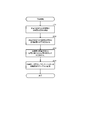
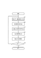
次いで、暗電流補正テーブルの作成と、自動露出制御の模式的な手順をフローチャートに従って説明する。 Next, a schematic procedure for creating a dark current correction table and automatic exposure control will be described with reference to a flowchart.
図5Aは、実際の撮影前の例えば工場出荷時に行う暗電流補正テーブル3の作成の手順を示している。ここで、まずステップ201では、固体撮像素子1a全体を非露光状態にして、複数の蓄積時間Tについて、暗電流測定部1abを含む全画素の蓄積電荷信号Os(pk)を測定する。そしてステップ202では、その測定結果から、全画素について蓄積時間Tと蓄積電荷信号Os(pk)との関係を求める。次にステップ203では、全画素について蓄積時間Tと蓄積電荷信号Os(pk)との関係から、暗電流測定部1abと画素生成部1aaの各画素又は各列との、所定の露光時間に対する暗電流成分の出力比α2を求める。最後にステップ204では、全画素に対応させて、その出力比α2とオフセットOfを暗電流補正テーブル3に記憶する。また、必要に応じて温度を異ならせて複数の蓄積時間について暗電流補正テーブルを記憶しておく。
FIG. 5A shows a procedure for creating the dark current correction table 3 that is performed at the time of factory shipment before actual photographing. Here, first, in
図5Bは、実際の撮影時に行う自動露出制御の処理手順を示している。ここで、まず、ステップ301では、X線撮影を行い、各画素の蓄積信号Osを出力させる。そして、ステップ302では、暗電流測定信号Os(p0)を抽出し、ステップ303では、注目画素1agからの蓄積電荷信号Os(pg)を抽出する。抽出する注目画素の蓄積信号Os(pg)は、一列でも複数列の信号でも良い。次に、ステップ304では、暗電流測定信号Os(p0)と蓄積電荷信号Os(pg)に対して、暗電流補正テーブル3に記憶しているα2(pk)を適用し演算して、露出制御信号Xを算出し、ステップ305では、その露出制御信号Xに基づいて、制御すべき目標値となる撮影光の強度を算出し、撮影と同時にフィードバック制御を行う。最後にステップ306では、処理終了を判定し、終了していなければ、ステップ301に戻る。このように実際の撮影に当っては、画素毎に事前に補正テーブルに記憶した電荷蓄積時間に対する撮影時に露光する画素と非露光にする画素との関係から実際の撮影時に測定した撮影時間と非露光の画素との関係から露光した画素の暗電流成分を予測して露出制御信号によってフィードバック制御するものである。この予測には、事前処理時の電荷蓄積時間も撮影時の電荷蓄積時間もパラメータとして使用しない。そのため、電荷蓄積時間を取り出す処理が不要となり、TDIクロック発生器をX線検出器の外に配置している仕様にも対応できる。また、このフィードバック制御としては具体的には、X線撮影の場合、X線走査速度、X線管電流、X線管電圧、階調処理のいずれか一つ又はそれらを組み合わせて制御する。
FIG. 5B shows a processing procedure of automatic exposure control performed at the time of actual photographing. Here, first, in
次いで、本発明をパノラマX線撮影が可能な医療用デジタルX線撮影装置に適用した例を詳細に説明する。 Next, an example in which the present invention is applied to a medical digital X-ray imaging apparatus capable of panoramic X-ray imaging will be described in detail.
図6は、そのX線撮影装置A2の外観図である。装置本体4の基台4aに支柱4bが立設され、この支柱4bに支持体5が昇降可能に取り付けられ、この支持体5に旋回アーム6が旋回可能に取り付けられている。支持体5の上端と下端とのそれぞれには、ほぼ水平に伸びた支持アーム5aと、被験者フレーム5bを設けてあり、被験者フレーム5bにはチンレスト5cが設けられている。
FIG. 6 is an external view of the X-ray imaging apparatus A2. A support column 4b is erected on a base 4a of the apparatus
支持アーム5aにはステップモータによってX方向、Y方向に自在に移動可能なXYテーブルが内蔵されており、旋回アーム6はこのXYテーブルを介して吊り下げられて水平面内を任意に移動しながら旋回できるようになっている。被験者頭部押え5dは支持アーム5aの下面に旋回アームを貫通して固定されている被験者固定手段であり、位置調整機構を備えている。
The support arm 5a has a built-in XY table that can be freely moved in the X and Y directions by a step motor. The
旋回アーム6には、ステップモータにより支持アーム5aに対して旋回アーム6を旋回させる旋回機構が設けられており、旋回アーム6は上記のXYテーブルにより旋回中心を移動させながら、垂直な軸線に対して旋回できるように構成されている。旋回アーム6は両端が垂下しており、一方の端部6aにはX線発生器7が、他方の端部6bにはX線検出部8が対向配設されている。X線発生器7には、X線管、縦方向の1次スリットを有するX線遮蔽板と、その1次スリットの形状を変更する調整機構(いずれも不図示)などが備えられている。
The turning
X線検出部8には、1次スリットに対応した縦方向の2次スリット9aと、その調整機構を有する遮蔽板9がX線発生器7に対向して設けられ、その背後に検出器ホルダ10が配置され、この検出器ホルダ10にX線撮影用検出器11Aが装着されている。
The
このX線検出部8の後部には、各種回路を組み込んだプリント基板などから構成される装置本体制御部12と、その外側を覆うように操作パネル13が設けられ、操作パネル13には各種のスイッチや操作表示部13aが取り付けられている(いずれも不図示)。
The rear portion of the
また、装置本体4には操作コード14aで接続されるリコモンボックス14Aが設けられており、これに例えば、電源オンオフ用のメインスイッチとX線照射スイッチが備えられている。X線検出部8には、X線撮影用検出器接続用のコネクタ15を設けてある。
Further, the
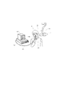
図7はX線撮影用検出器11Aの外観を説明する図であり、図8はその内部構成を説明する図面である。このX線撮影用検出器11Aは、内部にCCDセンサなどの固体撮像素子ユニット1を有し、これに関連する各種の回路を収用した外装ハウジング16で外装され、ハウジング16の一側面には外部回路との接続用コネクタ17が設けられている。このコネクタ17は、通常はX線検出部8のコネクタ15との間を給電線と信号線が一体となったケーブル(不図示)で接続されるが、パソコンなど他の外部機器との接続用にも利用できる。
FIG. 7 is a diagram for explaining the external appearance of the
外装ハウジング16はアルミ板等の金属やABS樹脂等の合成樹脂など、必要な強度が得られる適宜の材料で構成されている。前面中央にはX線に対する透過性が良好であるが、可視光線は遮蔽する材料、例えば、暗い色のABS樹脂で製されたX線受光部18が2次スリット8aの背後に縦方向に設けられ、その内側に固体撮像素子ユニット1が配置されている。
The exterior housing 16 is made of an appropriate material that can provide the required strength, such as a metal such as an aluminum plate or a synthetic resin such as ABS resin. An
固体撮像素子ユニット1は、図8に示すようにX線受光部18の裏側に設置され、照射されたX線を可視光線に変換する発光体(シンチレータ)1bと、この発光体1bの発光を固体撮像素子1aの受光面に伝達する光ファイバー1cと、後述する構成の固体撮像素子1aとで構成され、回路基板1dを有している。19は保護ケース、19aはX線を遮蔽するシール材、1eは固体撮像ユニット1の信号ピンである。ここでシール材19aの下部には、発光体1bをX線から遮蔽することによって、固体撮像素子1aの対応部分に後述する暗電流測定部1abを設定するための鉛板等を施したX線遮蔽部材19bが貼付形成されている。
As shown in FIG. 8, the solid-state
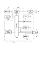
ここで、装置本体4の要部概略構成を図9を用いて説明し、次いでX線撮影用検出器11Aの要部概略を図10について説明する。
図9は、装置本体制御部20の要部概略構成を示すブロック図である。この制御部20には、X線撮影装置A2全体の動作制御の中心となるMPU(CPU)で構成された制御ユニット20a、入出力ポート20b、メモリ20cがあり、その他に図1の撮影光照射源7の具体例であるX線発生器7を駆動制御するX線照射制御回路20d、X線照射検出回路20e、旋回アーム回転検出回路20f、TDIクロック発生回路20g、通信制御回路20h、電源回路20iが設けられており、これらが入出力ポート20bを介して制御ユニット20aに接続されている。入出力ポート20bには、種々の操作データを入力するための操作パネル13、あるいは、同様の入力を本体から離れた位置から入力するためのリモコンボックス14が接続されている。そして更に、X線撮影用検出器11Aを接続するために、接続ケーブル21のコネクタ15′に対応したコネクタ15が設けられ、このコネクタ15には、入出力ポート20b、通信制御回路20h、電源回路20iが接続されている。
Here, a schematic configuration of the essential parts of the apparatus
FIG. 9 is a block diagram illustrating a schematic configuration of a main part of the apparatus main
図10は、X線撮影用検出器11Aの要部概略構成を示すブロック図である。このX線撮影用検出器11Aには、単独で、あるいは装置本体制御部20と一体となってX線撮影用検出器11A内の各回路の動作や装置本体4を含むX線撮影装置A2全体の動作を制御するMPU(CPU)で構成された制御ユニット11a、入出力ポート11b、TDIクロック変換回路11c、撮像素子駆動回路11d、A/D変換器11e、メモリ11f、通信制御回路11g、電源回路11h等が設けられ、これらの各回路とコネクタ17とが図示の通りに接続されている。そして、特にこの制御ユニット11aは、実施例1で説明した本発明の特徴である自動露出制御を行う演算制御手段2としての機能をソフトウェア処理によって発揮するようにされており、メモリ11fには、その画素処理手段が参照する暗電流補正テーブル3が予め工場出荷時に記憶されており、更にX線撮影時には、X線パノラマ画像を形成する有効画素を蓄積するためにも用いられる。
FIG. 10 is a block diagram showing a schematic configuration of a main part of the
またX線撮影用検出器11Aは、装置本体4に着脱可能にまたは固定して装着されて使用される構成とされ、そのためにコネクタ17は、装置本体制御部20から導出された接続ケーブル21に設けられたコネクタ17′によって、装置本体制御部20と電気的、制御的接続を行っている。また、装置本体制御部20は、装置本体制御部20自身とX線撮影用検出器11Aとに制御情報などを入力したり、逆にデータを出力して保存したりするために、パーソナルコンピュータなどで構成された外部機器100を接続したりすることができる構成とされている。なお、暗電流補正テーブル3が記憶されたメモリ11fは、
上記の例ではX線撮影用検出器11A内に設けたが、装置本体外に設けたコンピュータの
メモリを利用しても良い。
The X-ray imaging detector 11 </ b> A is configured to be used detachably or fixedly attached to the apparatus
In the above example, the
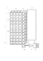
図11は、X線撮影用検出器11Aに備えられた固体撮像素子1aの概略構成を示す図面である。この固体撮像素子1aは、FFTタイプ(フルフレームトランスファー型)のCCDセンサで構成されている。ここで、1adは受光部を構成するセンサマトリクスであり、水平方向に蓄積電荷を転送するシフトレジスタ1aeを、上下に複数列形成して構成され、これらのシフトレジスタ1aeに形成されるポテンシャルウエルによって、列及び段に配置された画素eを形成した構造にしている。
FIG. 11 is a diagram showing a schematic configuration of the solid-
1acは上下に複数列形成して構成された各シフトレジスタ1aeのポテンシャルウエルを通じて一斉に水平方向に並列して転送されて来た蓄積電荷を垂直方向に転送するポテンシャルウエルを形成する別の蓄積電荷転送部、1afは蓄積電荷転送部1acから垂直方向にシリアル転送されて来る蓄積電荷を取り出すための出力ウエル、22は出力ウエル1afから、順次出力されて来る蓄積電荷を更に電圧信号に変換し、蓄積電荷信号として出力させる増幅器である。 1ac is another accumulated charge that forms a potential well that vertically transfers the accumulated charges transferred in parallel in the horizontal direction through the potential wells of the shift registers 1ae formed by forming a plurality of columns vertically. The transfer unit 1af is an output well for taking out the accumulated charge serially transferred in the vertical direction from the accumulated charge transfer unit 1ac, and 22 is further converted into a voltage signal from the accumulated charge sequentially output from the output well 1af. This is an amplifier that outputs an accumulated charge signal.
このセンサマトリクス1adは、図中では画素eが11列(垂直方向)4段(水平方向)の行列状に配置されているが、画素eは実際には1500列64段に配置されている。そして、受光部1adでは、図中の最下部以外の列に、画像を形成する画素を蓄積電荷として出力する画素生成部1aaを割り当て、最下部の列には、X線遮蔽部材19bがX線を遮蔽することによって、常に露光しない状態にされて暗電流測定信号を蓄積電荷として出力する暗電流測定部1abを割り当てている。更に、画素生成部1aaには、図示しないが、任意の位置の画素eを注目画素1agとして設定している。
In the sensor matrix 1ad, pixels e are arranged in a matrix of 11 columns (vertical direction) and 4 stages (horizontal direction) in the drawing, but the pixels e are actually arranged in 1500 columns and 64 stages. In the light receiving unit 1ad, the pixel generation unit 1aa that outputs the pixels forming the image as the accumulated charge is assigned to a column other than the lowermost portion in the drawing, and the
増幅器22から出力された蓄積電荷信号は、AD変換器11eに送出されてデジタル信号に変換されるようになっている。CCDセンサを構成するシフトレジスタ1ae、蓄積電荷転送部1ac、出力ウエル1afは、撮像素子駆動回路11dの生成する駆動クロックに従って、蓄積電荷の転送を行う。
The accumulated charge signal output from the amplifier 22 is sent to the
受光面を構成するセンサマトリクス1adのポテンシャルウエルに、光を照射して得た蓄積電荷を閉じ込めて半導体中を転送させるCCDセンサの電荷転送の基本動作は、既に特開平9−200625号公報などで周知であるが、この固体撮像素子1aの構成上の特徴は、センサマトリクス1adの一部に、常に露光しない状態にされて暗電流測定信号を蓄積電荷として出力する暗電流測定部1abを割り当てている点と、更に自動露出制御を行うために、画像生成部1aaの適した位置に、注目画素1agを設定している点である。なお、ここでのCCDセンサはフルフレームトランスファー型を例にして説明したが、FTタイプ(フレームトランスファー型)のCCDセンサであっても良い。また、下述の何れの実施例ともセンサの種類としては、CCDセンサの代わりにMOSセンサ、C−MOSセンサ、TFT(Thin Film Transistor)等の2次元フラットパネルセンサなどの固体撮像素子を使用することができる。また、上述のように照射されたX線を可視光線に変換する発光体1bによる可視光線を受光しているが、X線を直接検出するタイプのCCDセンサを用いる構成も可能である。
The basic operation of the charge transfer of the CCD sensor for confining the accumulated charge obtained by irradiating light to the potential well of the sensor matrix 1ad constituting the light receiving surface and transferring it in the semiconductor has already been disclosed in Japanese Patent Laid-Open No. 9-200265. As is well known, the structural feature of the solid-
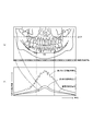
図12は、以上のように構成されたパノラマX線撮影装置A2で撮影されるパノラマX線画像の一例を示す図面であり、ここで(a)は全顎パノラマX線透過画像、(b)は画像生成部1aaの適した位置に設定された注目画素1agからの蓄積電荷信号と、暗電流測定部1abからの暗電流測定信号とを示すグラフである。 FIG. 12 is a drawing showing an example of a panoramic X-ray image captured by the panoramic X-ray imaging apparatus A2 configured as described above, where (a) is a full-jaw panoramic X-ray transmission image, and (b). These are graphs showing the accumulated charge signal from the target pixel 1ag set at a suitable position in the image generation unit 1aa and the dark current measurement signal from the dark current measurement unit 1ab.
図12(a)において、RZは、パノラマX線撮影する場合に通常適用される濃度補正領域であって、この領域では、頸椎などの障害陰影の影響を除去するため、より長い時間X線を照射するようにしており、その分だけ、旋回アーム6はゆっくり回転するようになっている。
In FIG. 12A, RZ is a density correction region that is usually applied when panoramic X-ray imaging is performed. In this region, X-rays for a longer period of time are removed in order to remove the influence of obstacle shadows such as the cervical spine. Irradiation is performed, and the
図12(b)から理解されるように、濃度補正領域では、暗電流測定信号は多くなっている。そして、注目画素1agからの蓄積電荷信号中の暗電流成分と、暗電流測定部1abからの暗電流測定信号とは、絶対強度に違いがあるものの、その強度は互いに比例関係を有している。
従って、実施例1で説明した方法によって、暗電流測定部1abからの暗電流測定信号に基づいて、注目画素1agからの蓄積電荷信号中の暗電流成分を予測演算して除去して露出制御信号を算出することが可能であり、この露出制御信号が一様な強度になるように、フィードバック制御できる。
As understood from FIG. 12B, the dark current measurement signal increases in the density correction region. The dark current component in the accumulated charge signal from the target pixel 1ag and the dark current measurement signal from the dark current measurement unit 1ab are different in absolute intensity, but the intensity is proportional to each other. .
Therefore, according to the method described in the first embodiment, based on the dark current measurement signal from the dark current measurement unit 1ab, the dark current component in the accumulated charge signal from the target pixel 1ag is predicted and removed, and the exposure control signal is output. Can be calculated, and feedback control can be performed so that the exposure control signal has a uniform intensity.
なお、この実施例では固体撮像素子1aとしてCCDセンサを用いているが、そのCCDセンサに替えて、各画素のフォトダイオードをMOSトランジスタで選択して電荷を取り出す構成のMOSセンサを用いることも可能である。
In this embodiment, a CCD sensor is used as the solid-
ついで、本発明をセファロX線撮影が可能な医療用デジタルX線撮影装置に適用した例を説明する。
図13は、そのX線撮影装置A3の外観正面図である。このX線撮影装置A3は、実施例2で説明した図6のX線撮影装置A2において、セファロX線撮影用に、X線撮影用検出器11Bを更に着脱可能に装着可能にすると共に、撮影対象である被験者頭部Hを固定支持するセファロ用支持装置23を更に備えており、パノラマX線撮影だけでなく、セファロX線撮影も行うことができる。
Next, an example in which the present invention is applied to a medical digital X-ray imaging apparatus capable of performing cephalo X-ray imaging will be described.
FIG. 13 is an external front view of the X-ray imaging apparatus A3. In the X-ray imaging apparatus A2 of FIG. 6 described in the second embodiment, the X-ray imaging apparatus A3 enables the
このX線撮影用検出器11Bは、実施例2のX線撮影装置A2に用いられているX線撮影用検出器11Aと同様の構成である。また、リモコンボックス14Bは、図6のリモコンボックス14Aと同様のものであるが、パノラマX線撮影とセファロX線撮影のいずれの場合にも使用できるように、その設置位置と操作できる内容が変更されたものである。
The
セファロX線撮影の場合には、従来技術と同様に、X線検出部8がX線発生器7のX線放射領域から外れ、X線発生器7からのX線はセファロ用支持装置23に固定された被験者頭部Hを透過して、X線撮影用検出器11Bに到達すようになっている。この時には、X線撮影用検出器11Bは、そのX線受光部18が被験者頭部H全体のX線透過画像を受光するようにセファロ用支持装置31に対して上下又は左右に移動可能となっている。
In the case of cephalometric X-ray imaging, the
図14はセファロX線撮影時における、X線発生器7、被験者頭部H、X線撮影用検出器11Bの3者の位置関係を説明する図面である。図のように、X線発生器7から照射されたX線は、1次スリットによって角錐状に照射範囲を制限され、1次スリットとX線撮影用検出器11Bとを連動させて移動させることによってX線ビームを、被験者頭部Hを透過し、X線撮影用検出器11Bが被験者頭部H全体のX線透過画像を受光するように左右方向に左右に移動するようになっている。
FIG. 14 is a diagram for explaining the positional relationship among the three of the
このようなセファロX線撮影においても、X線撮影装置A3に用いられているX線撮影用検出器11Bは、実施例2のX線撮影装置A2のX線撮影用検出器11Aと同様の構成とされているから、実施例1で説明した方法によって自動露出制御を行うことができる。
In such cephalometric X-ray imaging, the
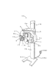
ついで、本発明をリニアスキャンX線撮影が可能な医療用デジタルX線撮影装置に適用した例を説明する。
図15は、そのX線撮影装置A4の全体概略構成を示すブロック図である。このX線撮影装置A4はリニアスキャンX線撮影を行うものであって、X線発生器7と、このX線発生器7から照射され撮影対象を透過したX線細隙ビームBを受光するX線撮影用検出器11Cと、このX線撮影用検出器11Cを着脱可能にかつ速度調整可能に移動保持する検出器ホルダ10と、撮影対象である被験者頭部Hを固定する被験者頭部押え(被写体固定手段)5dと、被写体の階調処理基準点位置を検出する位置検出手段32と、この装置全体を制御する装置本体4とを備えている。
Next, an example in which the present invention is applied to a medical digital X-ray imaging apparatus capable of linear scan X-ray imaging will be described.
FIG. 15 is a block diagram showing an overall schematic configuration of the X-ray imaging apparatus A4. The X-ray imaging apparatus A4 performs linear scan X-ray imaging, and receives an
なおここで、X線発生器7、X線撮影用検出器11C、走査用検出器支持部33、被写体固定手段5d、位置検出手段32については、いずれもこれらを、その通常の使用状態を上方から見た所を平面的に示したものである。また、X線撮影用検出器11Cは、実施例2のX線撮影装置A2に用いられているX線撮影用検出器11Aと同様の構成である。
It should be noted that the
X線発生器7はX線管を内蔵しており、更にそこから広域に発射されるX線ビームを一定方向、一定範囲だけに制限して目的箇所に照射させるための開口である1次スリット7aを形成したX線遮蔽材よりなる1次スリット部材7bと、この1次スリット部材7bを図示するD方向に速度、位置調整可能に移動させる1次スリット移動軸7cと、この1次スリット移動軸7cを駆動する1次スリット移動モータM1とを備えている。
The
X線撮影用検出器支持部33は、X線撮影用検出器11Cを着脱可能に保持する検出器ホルダ10と、この検出器ホルダ10を図示するD方向に速度、位置調整可能に移動させる検出器移動軸33aと、この移動軸33aを駆動する検出器移動モータM2と、X線発生器7の1次スリット7aで制限されたX線細隙ビームBが被験者頭部Hに照射される前に、更に一定範囲だけに制限するためのX線通過開口である2次スリット34aを有しX線遮蔽材で形成された2次スリット部材34bと、この2次スリット部材34bを図示するD方向に速度、位置調整可能に移動させる2次スリット移動軸33cと、この2次スリット移動軸33cを駆動する2次スリット移動モータM3とを備えている。なお、検出器移動モータM2と2次スリット移動モータM3とを独立別個に設けることなく、両者をタイミングベルトなどで機構的にリンクさせて、一方のモータを不要とすることも可能である。
The X-ray imaging
被験者頭部押え(被写体固定手段)5dは、X線撮影用検出器支持部33の検出器ホルダ10や2次スリット部材34bの方向Dへの移動に拘わらず、被験者頭部Hを所定位置に固定しておくように構成されている。
The subject head presser (subject fixing means) 5d places the subject head H in a predetermined position regardless of the movement of the
装置本体4は、MPU(CPU)で構成され中央制御機能を発揮する制御ユニット20aと、制御ユニット20aが処理する種々の制御プログラムなどを記憶保存するメモリ20cと、X線照射制御回路20dと、モータ制御回路20fと、TDIクロック発生回路と、通信制御回路20hなどで構成されている制御部20と、種々の操作指示を受け付ける操作パネル13と、X線画像などを表示する表示装置13aとを備えている。モータ制御回路20fには、1次スリット移動モータM1、検出器移動モータM2、2次スリット移動モータM3を接続して制御している。
The
このX線撮影装置A4では、図示したようにX線発生器7とX線撮影用検出器11Cとが被写体固定手段5dを挟むように設けられ、被験者頭部押え(被写体固定手段)5dで固定された被験者頭部Hに対して相対的に、1次スリット7aと2次スリット34aとX線撮影用検出器11Cとを同期して移動させることで、X線発生器7から照射されるX線細隙ビームBとX線撮影用検出器11Cとを同方向Dに同期して移動させながら、X線細隙ビームBで被験者頭部Hを走査し、被験者頭部HのリニアスキャンX線画像を得るようになっている。その際には、走査中のX線撮影用検出器11Cによって得られたX線受光データである蓄積電荷信号を元に、X線細隙ビームBの走査速度(方向Dへの移動速度)を制御している。
In this X-ray imaging apparatus A4, as shown in the figure, an
つまり、硬組織領域を走査している途中で、透過量が大きい場合には、走査速度を大きくすることによって、この軟組織領域に単位時間あたりに照射されるX線細隙ビームBの線量を少なくする一方、透過量が小さい場合には、走査速度を小さくすることで、この硬組織領域に単位時間あたりに照射されるX線細隙ビームBの線量を多くする制御を行う。 That is, when the transmission amount is large during scanning of the hard tissue region, the dose of the X-ray slit beam B irradiated to the soft tissue region per unit time is reduced by increasing the scanning speed. On the other hand, when the amount of transmitted light is small, control is performed to increase the dose of the X-ray slit beam B irradiated to the hard tissue region per unit time by reducing the scanning speed.
更に、このようなリニアスキャンX線撮影においても、X線撮影装置A4に用いられているX線撮影用検出器11Cは、実施例2で説明したX線撮影装置A2のX線撮影用検出器11Aと同様の構成とされているから、実施例1で説明した方法によって自動露出補正を行うことができる。
Further, even in such linear scanning X-ray imaging, the
図16は、図15で示した位置検出手段32の要部説明図である。この位置検出手段32は、接触子32aと、この接触子32aを矢印で示すように例えば上下左右に位置調節可能かつ位置検知可能に支持し、被験者頭部Hの階調処理基準点Pに接触子32aを当接させた時の位置を検出する位置検出器32bとを備えている。この位置検出器32bは、被験者頭部押え(被写体固定手段)5dに固定されたポテンショメータなどで構成される。
FIG. 16 is an explanatory view of a main part of the position detecting means 32 shown in FIG. The position detection means 32 supports the
このような位置検出手段32を用いると、階調処理基準点P(この例では歯科用セファロ撮影でよく用いられるナジオン、つまり、歯科矯正において重要な、人体頭部正中状平面における鼻骨前頭縫合の最前点)の位置を簡単、短時間にかつ正確に検出することができ、また、被験者に余分な検出用マークを付したりしないで済む。なお、この階調処理基準点Pは、ナジオンの位置に限られるものではなく、公知の各位置を用いることができる。 When such a position detection means 32 is used, a gradation processing reference point P (in this example, nadione often used in dental cephalometric imaging, that is, nasal frontal suture in the midline plane of the human head, which is important in orthodontics, is used. The position of the foremost point) can be detected easily, in a short time and accurately, and it is not necessary to place an extra detection mark on the subject. The gradation processing reference point P is not limited to the position of nadion, and any known position can be used.
こうして得られた階調処理基準点Pは、X線撮影用検出器11Cで得られたリニアスキャンX線画像に対して、事後的に軟組織領域の階調処理をするため、あるいは、X線撮影をする際のX線細隙ビームBの照射量を制御するために用いられる。
The gradation processing reference point P obtained in this way is used to perform the gradation processing of the soft tissue region later on the linear scan X-ray image obtained by the
なお、温度に対応させて、複数組の暗電流補正テーブル3…3を用意しておき、撮影時の温度によって適切な暗電流補正テーブル3を選択して、暗電流の補正を行う方法も可能である。このときには、暗電流成分を除去するにあたり、予め記憶させた暗電流成分の温度に基づく変動成分を更に除去することになるので、更に良好な自動露出制御結果が得られる。 It is also possible to prepare a plurality of sets of dark current correction tables 3... 3 corresponding to the temperature, select the appropriate dark current correction table 3 according to the temperature at the time of shooting, and correct the dark current. It is. In this case, when removing the dark current component, the fluctuation component based on the temperature of the dark current component stored in advance is further removed, so that a better automatic exposure control result can be obtained.
ついで、本発明をデンタルX線撮影が可能な医療用デジタルX線撮影装置に適用した例を説明する。
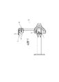
図17は、そのX線画像撮影装置A5の使用形態を説明する図面である。図のように、X線画像撮影装置A5は、撮影対象を口腔内部位とするものである。
Next, an example in which the present invention is applied to a medical digital X-ray imaging apparatus capable of performing dental X-ray imaging will be described.
FIG. 17 is a diagram illustrating a usage pattern of the X-ray imaging apparatus A5. As shown in the figure, the X-ray imaging apparatus A5 uses an imaging target as an intraoral site.
X線発生器7は、自在アーム33に対して上下揺動自在および水平回転自在に取り付けられ、口腔内部位に向けてX線を照射するように、X線照射筒7dの方向が調整される。一方、口腔内部位を挟んでX線照射筒7dと対向する位置に、口腔内部位を通過したX線強度分布、すなわちX線像を検出するためのX線撮影用検出器11Dが位置決めされる。すなわち、X線撮影用検出器11Dの撮像面がX線照射方向に適切に向くように、X線撮影用検出器11Dを取り付けた位置決め具34を被験者自身が指で保持するようになっている。
The
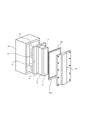
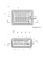
図18は、X線撮影用検出器11Dの構成を示す断面図であり、(a)はA−A線に沿った水平断面図で、(b)はB−B線に沿った縦断面図である。
X線撮影用検出器11Dは、照射されたX線を可視光線に変換する発光体(シンチレータ)1bと、この発光体1bの発光を固体撮像素子1aの受光面に伝達する光ファイバー1cと、光ファイバー1cで伝達された蛍光分布を受光して発生した電荷を蓄積し、所定時間蓄積した電荷を順次読出して電気信号に変換するCCDセンサで構成された固体撮像素子1aと、固体撮像素子1aを支持するセラミックなどの基板1dと、各構成部品を収納するための保護ケース19などで構成されている。
18A and 18B are cross-sectional views showing the configuration of the
The
保護ケース19内側のX線露光面と側面とには、発光体1b、光ファイバー1c、を固体撮像素子1aおよび基板1dを包囲するようにアルミニウムまたは銅の薄層などの導電部材35を被設して、外来からの誘導ノイズや静電サージ等の影響が、固体撮像素子1a等に及ばないようにして、耐ノイズ性や耐サージ性を向上させている。なお、導電部材35の材質は、アルミニウムやベリリウムなどの原子量の小さいものが好ましく、その厚さを極力薄く、たとえば0.01mm〜0.1mm程度に形成しているため、X線撮影用検出器11Dに入射するX線の減衰や散乱を殆ど引き起こさない。
A
そして、保護ケース19内側の裏面と側面とには、X線を遮蔽するシール材19aを被設して、基板1dの背面や側面への不要な散乱X線の入射を防止している。保護ケース27内側の露光面の一部にも、固体撮像素子1a暗電流測定部1abを設定するために、シール材19aで形成されたX線遮蔽部材19bを設けている。
And the sealing
更に、基板1dには、X線撮影用検出器11A〜11Cと同様に、MPU(CPU)で構成され、暗電流の補正を実行する画像処理手段2の機能有する制御ユニット11a(不図示)や、その画像処理手段2が参照する暗電流補正テーブル3を予め記憶しているメモリ11f(不図示)などが、実施例2−4と同様に設けられている。従って、X線撮影時に固体撮像素子1aから出力された蓄積電荷信号は、画像処理手段2によって暗電流成分を除去され、デンタルX線画像としてメモリ11fに蓄積され、ケーブル21を通じて操作パネル13に入力され、表示装置13Aに画像として表示される。
Further, on the
このX線画像撮影装置A5に用いられるX線撮影用検出器11Dと、実施例2−4の各X線画像撮影装置に用いられているX線撮影用検出器11A〜11Cとの違いについて説明する。
すなわち、実施例2−4のX線撮影用検出器11A〜11Cでは、図11を参照して説明したように、CCDセンサの受光部1adの最下部以外の列に、画像を形成する画素を蓄積電荷として出力する画素生成部1aaを割り当て、各列から出力される電荷を時間遅延積分して1画素の蓄積電荷信号としていた(蓄積電荷信号は1次元画像を形成する)のに対し、X線撮影用検出器11Dでは、各画素eからの電荷を2次元画像を形成する蓄積電荷信号として扱うようになっている。
The difference between the
That is, in the
しかし、各画素eからの電荷を2次元画像を形成する蓄積電荷信号として扱う場合であっても、非露光状態での暗電流測定部1abと画素生成部1aaの各画素eとの、所定の露光時間に対するおける出力比を暗電流補正テーブル3に予め記憶しておく。そして、X線撮像時において、注目画素1agより取り出された蓄積電荷信号とに対して、暗電流測定部1abから取り出される暗電流測定信号と暗電流補正テーブル3に記憶しておいたその出力比を適用した演算とにより暗電流成分を除去して露出制御信号を算出する方法を採ることができる。よって、ここでも本発明の思想による自動露出制御を行うことができる。 However, even when the charge from each pixel e is handled as an accumulated charge signal for forming a two-dimensional image, a predetermined current between the dark current measuring unit 1ab in the non-exposure state and each pixel e in the pixel generation unit 1aa Contact Ku prestores output ratio definitive with respect to the exposure time to the dark current correction table 3. Then, during X-ray imaging, the dark charge measurement signal taken out from the dark current measurement unit 1ab and the output ratio stored in the dark current correction table 3 with respect to the accumulated charge signal taken out from the target pixel 1ag. method of calculating an exposure control signal to remove the dark current components by the operation of applying can take. Therefore, automatic exposure control according to the idea of the present invention can be performed here.
なお、この実施例でも固体撮像素子1aとしてCCDセンサを用いているが、そのCCDセンサに替えて、各画素のフォトダイオードをMOSトランジスタで選択して電荷を取り出す構成のMOSセンサを用いることも可能である。
In this embodiment, a CCD sensor is used as the solid-
また、温度に対応させて、複数組の暗電流補正テーブル3…3を用意しておき、撮影時の温度によって適切な暗電流補正テーブル3を選択して、暗電流の補正を行う方法も可能である。このときには、暗電流成分を除去するにあたり、予め記憶させた暗電流成分の温度に基づく変動成分を更に除去することになるので、更に良好な自動露出制御結果が得られる。 Further, a method of preparing a plurality of sets of dark current correction tables 3... 3 corresponding to the temperature, and correcting the dark current by selecting an appropriate dark current correction table 3 according to the temperature at the time of photographing is also possible. It is. In this case, when removing the dark current component, the fluctuation component based on the temperature of the dark current component stored in advance is further removed, so that a better automatic exposure control result can be obtained.
本発明は、上記実施例の医療用デジタルX線撮影装置の外、X線CT(コンピュータ・トモグラフィー)撮影装置にも適用可能である。すなわち、CT画像は、同一の被写体に対して角度を変えて何枚も透過X線撮影を行い、そこで得たX画像を処理して断層画像を得るものであるから、それぞれの透過X線撮影において、本発明の自動露出制御を行うことが可能である。 The present invention can be applied to an X-ray CT (computer tomography) imaging apparatus in addition to the medical digital X-ray imaging apparatus of the above embodiment. That is, CT images are obtained by performing transmission X-ray imaging at various angles on the same subject, and processing the X images obtained there to obtain tomographic images. The automatic exposure control according to the present invention can be performed.
なお、上述の実施例2−6では、医療用デジタルX線撮影装置に、本発明の自動露出制御方法を適用しているが、この自動露出制御方法は、医療用デジタルX線撮影装置だけでなく、照射源から被対象物に可視光を含む照射光を照射して画像を生成する一般の画像生成装置に適用できる。 In Example 2-6 described above, the automatic exposure control method of the present invention is applied to the medical digital X-ray imaging apparatus. However, this automatic exposure control method is performed only by the medical digital X-ray imaging apparatus. However, the present invention can be applied to a general image generation apparatus that generates an image by irradiating an object including irradiation light from an irradiation source.
1a 固体撮像素子
1aa 画素生成部
1ab 暗電流測定部
1ag 注目画素
2 制御演算手段
3 暗電流テーブル
A2 パノラマX線撮影が可能な医療用デジタルX線撮影装置
A3 セファロX線撮影が可能な医療用デジタルX線撮影装置
A4 リニアスキャンX線撮影が可能な医療用デジタルX線撮影装置
A5 デンタルX線撮影が可能な医療用デジタルX線撮影装置
DESCRIPTION OF
Claims (8)
上記固体撮像素子が、上記X線を受けて発生した電荷を蓄積する画素生成部と、上記X線を受けないで暗電流成分を蓄積する暗電流測定部とを備え、
上記固体撮像素子を非露光状態とした上記画素生成部の出力に基づく暗電流成分と上記暗電流測定部の出力に基づく暗電流成分とによる出力比を、上記画素生成部で注目する画素又は画素列について算出して予めメモリに記憶しておき、
上記固体撮像素子がX線を受けているときに、
上記暗電流測定部が出力した蓄積電荷信号に対して記憶された上記出力比を適用する演算により、上記画素生成部で注目する画素又は画素列に対する暗電流成分を算出し、
上記画素生成部で注目する画素又は画素列の蓄積電荷信号から上記算出された暗電流成分を減算した値を算出することで、暗電流成分を除去した露出測定信号を取得し、
該露出測定信号により上記X線の強度を決定することで、上記X線の強度をX線撮影時にフィードバック制御することを特徴とするX線撮影画像の自動露出制御方法。 Automatic exposure that controls the image generated by the solid-state imaging device to be within a predetermined density range by feedback control of the intensity of X-rays irradiated to the object from the X-ray generator for X-ray imaging A control method,
The solid-state imaging device includes a pixel generation unit that accumulates charges generated by receiving the X-rays, and a dark current measurement unit that accumulates dark current components without receiving the X-rays ,
A pixel or a pixel to which an attention is paid in the pixel generation unit with respect to an output ratio between the dark current component based on the output of the pixel generation unit and the dark current component based on the output of the dark current measurement unit in which the solid-state imaging device is in an unexposed state. Calculate the column and store it in memory beforehand.
When the solid-state imaging device receives X-rays,
By calculating the stored output ratio with respect to the accumulated charge signal output by the dark current measurement unit, the dark current component for the pixel or pixel column of interest in the pixel generation unit is calculated,
By calculating a value obtained by subtracting the calculated dark current component from the accumulated charge signal of the pixel or pixel column of interest in the pixel generation unit, an exposure measurement signal from which the dark current component has been removed is obtained,
An automatic exposure control method for an X-ray image, wherein the X-ray intensity is feedback-controlled during X-ray imaging by determining the X-ray intensity based on the exposure measurement signal.
上記メモリに記憶する上記出力比が、上記画素生成部の蓄積電荷信号の露光時間に対する出力変化の傾きと、上記暗電流測定部の蓄積電荷信号の露光時間に対する出力変化の傾きとの比であることを特徴とするX線撮影画像の自動露出制御方法。 In claim 1 ,
The output ratio stored in the memory is a ratio between the slope of the output change with respect to the exposure time of the accumulated charge signal of the pixel generation unit and the slope of the output change with respect to the exposure time of the accumulated charge signal of the dark current measurement unit. An automatic exposure control method for an X-ray image.
上記X線の強度は、制御目標値に向けて、所定の遅延要素を加えるようにしてフィードバック制御することを特徴とするX線撮影画像の自動露出制御方法。 In claim 1 or claim 2 ,
An X-ray image automatic exposure control method, wherein the X-ray intensity is feedback-controlled by adding a predetermined delay element toward a control target value.
上記照射源をX線を照射するX線発生器とし、
上記固体撮像素子が、該X線発生器からのX線を受けて可視光を生成する構成を有することを特徴とするX線撮影画像の自動露出制御方法。 In any one of Claims 1-3 ,
The irradiation source is an X-ray generator that emits X-rays,
An automatic exposure control method for an X-ray image, wherein the solid-state imaging device has a configuration for receiving visible X-rays from the X-ray generator.
上記撮影は、パノラマX線撮影、セファロX線撮影、リニアスキャンX線撮影、デンタルX線撮影又はCT撮影のいずれかを行うことを特徴とするX線撮影画像の自動露出制御方法。 In claim 4 ,
An automatic exposure control method for an X-ray image, wherein the imaging is performed by any of panoramic X-ray imaging, Cephalo X-ray imaging, linear scan X-ray imaging, dental X-ray imaging, or CT imaging.
X線走査速度、X線管電流、X線管電圧のうちの少なくとも1つ以上を制御して、上記X線強度のフィードバック制御を実行することを特徴とするX線撮影画像の自動露出制御方法。 In claim 4 or 5 ,
An automatic exposure control method for an X-ray image, wherein the X-ray intensity feedback control is performed by controlling at least one of an X-ray scanning speed, an X-ray tube current, and an X-ray tube voltage. .
上記X線を受けて発生した電荷を蓄積する画素生成部と、X線を受けないで暗電流成分を蓄積する暗電流測定部とを備えた固体撮像素子と、
上記画素生成部で注目する画素又は画素列について算出された、上記固体撮像素子を非露光状態とした上記画素生成部の出力に基づく暗電流成分と上記暗電流測定部の出力に基づく暗電流成分とによる出力比を、予め記憶させたメモリと、
上記暗電流測定部が出力した蓄積電荷信号に対して記憶された上記出力比を適用した演算により、上記画素生成部で注目する画素又は画素列に対する撮像時における暗電流成分を算出し、当該撮像時における暗電流成分を上記画素生成部で注目する画素又は画素列の蓄積電荷信号から減算した値を算出することで、暗電流成分を除去した露出測定信号を取得し、該露出測定信号により上記X線の強度を決定することで、上記X線の強度をX線撮影時にフィードバック制御する制御手段とを備えたことを特徴とするX線撮影画像の自動露出制御装置。 An automatic exposure control device in a medical digital X-ray imaging apparatus that obtains an X-ray imaging image within a predetermined density range by feedback controlling the intensity of X-rays irradiated for X-ray imaging from an X-ray generator There,
A solid-state imaging device including a pixel generation unit that accumulates charges generated by receiving the X-rays, and a dark current measurement unit that accumulates dark current components without receiving X-rays;
The dark current component based on the output of the pixel generation unit and the dark current component based on the output of the dark current measurement unit, which are calculated for the pixel or pixel column of interest in the pixel generation unit and the solid-state imaging device is in an unexposed state A memory in which the output ratio of
A dark current component at the time of imaging of the pixel or pixel column of interest is calculated by the pixel generation unit by calculation applying the stored output ratio to the accumulated charge signal output by the dark current measurement unit , and the imaging the dark current component by calculating a value obtained by subtracting from the accumulated charge signals of the pixels or pixel column of interest in the pixel generation unit acquires the exposure measurement signal obtained by removing the dark current component, the by the exposed measuring signal during An automatic exposure control apparatus for an X-ray image, comprising: a control unit that feedback-controls the X-ray intensity during X-ray imaging by determining the X-ray intensity.
X線走査速度、X線管電流、X線管電圧、階調処理のうちの少なくとも1つ以上を制御することによって、上記X線強度のフィードバック制御を実行することを特徴とするX線撮影画像の自動露出制御装置。 In claim 7 ,
X-ray imaging image, wherein the X-ray intensity feedback control is executed by controlling at least one of an X-ray scanning speed, an X-ray tube current, an X-ray tube voltage, and gradation processing. Automatic exposure control device.
Priority Applications (4)
| Application Number | Priority Date | Filing Date | Title |
|---|---|---|---|
| JP2004136620A JP4264382B2 (en) | 2004-04-30 | 2004-04-30 | Automatic exposure control method for photographed image and automatic exposure control apparatus using the method |
| US11/119,510 US7262399B2 (en) | 2004-04-30 | 2005-04-28 | Automatic exposure control method of image and automatic exposure control system using the method |
| FI20050457A FI121051B (en) | 2004-04-30 | 2005-04-29 | Automatic Image Exposure Adjustment Method and Auto Exposure Adjustment System using this method |
| DE102005020160.1A DE102005020160B4 (en) | 2004-04-30 | 2005-04-29 | Method and device for automatic image exposure control |
Applications Claiming Priority (1)
| Application Number | Priority Date | Filing Date | Title |
|---|---|---|---|
| JP2004136620A JP4264382B2 (en) | 2004-04-30 | 2004-04-30 | Automatic exposure control method for photographed image and automatic exposure control apparatus using the method |
Publications (3)
| Publication Number | Publication Date |
|---|---|
| JP2005312810A JP2005312810A (en) | 2005-11-10 |
| JP2005312810A5 JP2005312810A5 (en) | 2008-10-30 |
| JP4264382B2 true JP4264382B2 (en) | 2009-05-13 |
Family
ID=34510731
Family Applications (1)
| Application Number | Title | Priority Date | Filing Date |
|---|---|---|---|
| JP2004136620A Expired - Fee Related JP4264382B2 (en) | 2004-04-30 | 2004-04-30 | Automatic exposure control method for photographed image and automatic exposure control apparatus using the method |
Country Status (4)
| Country | Link |
|---|---|
| US (1) | US7262399B2 (en) |
| JP (1) | JP4264382B2 (en) |
| DE (1) | DE102005020160B4 (en) |
| FI (1) | FI121051B (en) |
Families Citing this family (33)
| Publication number | Priority date | Publication date | Assignee | Title |
|---|---|---|---|---|
| FR2888044B1 (en) * | 2005-07-01 | 2007-08-31 | Atmel Grenoble Soc Par Actions | IMAGE SENSOR WITH CORNERS |
| JP2007175294A (en) * | 2005-12-28 | 2007-07-12 | Ge Medical Systems Global Technology Co Llc | Image sensor, control method thereof, X-ray detector and X-ray CT apparatus |
| WO2008033184A2 (en) * | 2006-09-13 | 2008-03-20 | Exxonmobil Upstream Research Company | Rapid inversion of electromagnetic reconnaissance survey data |
| GB2468446B (en) | 2007-12-12 | 2011-09-21 | Exxonmobil Upstream Res Co | Method and apparatus for evaluating submarine formations |
| KR100941499B1 (en) | 2008-01-15 | 2010-02-10 | (주)이우테크놀로지 | X-ray camera with mammoth function |
| JP2009260871A (en) * | 2008-04-21 | 2009-11-05 | Nikon Corp | Imaging device |
| KR100994836B1 (en) | 2008-04-25 | 2010-11-17 | 주식회사바텍 | Dental x-ray imaging system with large digital sensor |
| EP2221848A1 (en) * | 2009-02-18 | 2010-08-25 | LightLab Sweden AB | X-ray source comprising a field emission cathode |
| JP5663015B2 (en) | 2009-07-31 | 2015-02-04 | イメージング・サイエンシィズ・インターナショナル・エルエルシー | Dental panoramic imaging using segmentation and master arch |
| US8873712B2 (en) * | 2010-04-13 | 2014-10-28 | Carestream Health, Inc. | Exposure control using digital radiography detector |
| EP2598915B1 (en) | 2010-07-27 | 2018-11-07 | Exxonmobil Upstream Research Company | Inverting geophysical data for geological parameters or lithology |
| WO2012024025A1 (en) | 2010-08-16 | 2012-02-23 | Exxonmobil Upstream Research Company | Reducing the dimensionality of the joint inversion problem |
| US9453929B2 (en) | 2011-06-02 | 2016-09-27 | Exxonmobil Upstream Research Company | Joint inversion with unknown lithology |
| WO2012173718A1 (en) | 2011-06-17 | 2012-12-20 | Exxonmobil Upstream Research Company | Domain freezing in joint inversion |
| US9494711B2 (en) | 2011-07-21 | 2016-11-15 | Garrett M Leahy | Adaptive weighting of geophysical data types in joint inversion |
| CN102846328B (en) * | 2012-08-23 | 2014-07-02 | 上海奕瑞光电子科技有限公司 | Automatic exposure controlling device and controlling method for digital photography |
| DE102012215563A1 (en) * | 2012-09-03 | 2014-03-06 | Siemens Aktiengesellschaft | Dose-measuring device |
| US10591638B2 (en) | 2013-03-06 | 2020-03-17 | Exxonmobil Upstream Research Company | Inversion of geophysical data on computer system having parallel processors |
| CN111225161B (en) * | 2013-03-14 | 2023-04-18 | 株式会社尼康 | Image pickup element and image pickup apparatus |
| US11363938B2 (en) * | 2013-03-14 | 2022-06-21 | Ormco Corporation | Feedback control mechanism for adjustment of imaging parameters in a dental imaging system |
| US9846255B2 (en) | 2013-04-22 | 2017-12-19 | Exxonmobil Upstream Research Company | Reverse semi-airborne electromagnetic prospecting |
| JPWO2015076082A1 (en) * | 2013-11-22 | 2017-03-16 | 株式会社日立製作所 | Magnetic resonance imaging system |
| JP6482827B2 (en) * | 2014-11-14 | 2019-03-13 | 株式会社Keenメディカルフィジックス | Irradiation position detector |
| CN105741239B (en) * | 2014-12-11 | 2018-11-30 | 合肥美亚光电技术股份有限公司 | Generation method, device and the panorama machine for shooting tooth of tooth panoramic picture |
| CN106959314B (en) * | 2017-03-31 | 2024-07-05 | 上海品臻影像科技有限公司 | Testing device |
| JP7046698B2 (en) * | 2018-04-24 | 2022-04-04 | 浜松ホトニクス株式会社 | Radiation detector, manufacturing method of radiation detector, and image processing method |
| CN111227854B (en) | 2018-11-28 | 2024-01-26 | 上海西门子医疗器械有限公司 | Automatic exposure control method, storage medium and medical equipment for X-ray imaging |
| EP3777693B1 (en) * | 2019-08-12 | 2022-03-16 | DENTSPLY SIRONA Inc. | Measurement and data communication device for an intraoral dental radiology system |
| FR3115192A1 (en) * | 2020-10-15 | 2022-04-22 | Trixell | Method for real-time exposure control of an X-ray dose |
| JP7718879B2 (en) * | 2021-07-08 | 2025-08-05 | 株式会社ニューフレアテクノロジー | Image acquisition method and image acquisition device |
| CA3227077A1 (en) | 2021-08-11 | 2023-02-16 | Ryan KLEBBA | Dynamic fixed pattern noise calibrations |
| CN113992908B (en) * | 2021-10-26 | 2023-06-09 | 西安微电子技术研究所 | Method and system for calculating dark current of CMOS image sensor |
| US12335643B2 (en) * | 2023-03-16 | 2025-06-17 | Cista System Corp. | Apparatus and method of dark current calibration and correction |
Family Cites Families (14)
| Publication number | Priority date | Publication date | Assignee | Title |
|---|---|---|---|---|
| DE3529108A1 (en) | 1985-08-14 | 1987-02-26 | Philips Patentverwaltung Gmbh, 2000 Hamburg | METHOD FOR PRODUCING AN X-RAY IMAGING BY MEANS OF A PHOTOConductor and ARRANGEMENT FOR IMPLEMENTING THE METHOD |
| JPH02164184A (en) * | 1988-12-19 | 1990-06-25 | Toshiba Corp | X-ray diagnostic equipment |
| US5331682A (en) * | 1991-11-25 | 1994-07-19 | General Electric Company | Radiation detector offset and afterglow compensation technique |
| JP3255371B2 (en) | 1992-07-22 | 2002-02-12 | 浜松ホトニクス株式会社 | X-ray imaging device |
| DE69429142T2 (en) * | 1993-09-03 | 2002-08-22 | Koninklijke Philips Electronics N.V., Eindhoven | X-ray image |
| US5617462A (en) * | 1995-08-07 | 1997-04-01 | Oec Medical Systems, Inc. | Automatic X-ray exposure control system and method of use |
| US5693948A (en) | 1995-11-21 | 1997-12-02 | Loral Fairchild Corporation | Advanced CCD-based x-ray image sensor system |
| DE19605618A1 (en) * | 1996-02-15 | 1997-08-21 | Hauni Maschinenbau Ag | Method and device for determining the density of a fiber strand of the tobacco processing industry |
| DE19734717A1 (en) * | 1997-08-11 | 1999-02-25 | Sirona Dental Systems Gmbh | Method for compensating the dark current when creating dental panoramic and / or cephalometric slice images |
| JP3708347B2 (en) | 1998-12-21 | 2005-10-19 | 松下電器産業株式会社 | Panoramic X-ray equipment |
| US6453008B1 (en) * | 1999-07-29 | 2002-09-17 | Kabushiki Kaisha Toshiba | Radiation detector noise reduction method and radiation detector |
| AU782164B2 (en) * | 2000-02-02 | 2005-07-07 | Gendex Corporation | Automatic x-ray detection for intra-oral dental x-ray imaging apparatus |
| US6459765B1 (en) * | 2000-12-28 | 2002-10-01 | Ge Medical Systems Global Technology Company, Llc | Automatic exposure control and optimization in digital x-ray radiography |
| US6713769B2 (en) * | 2002-02-07 | 2004-03-30 | Ge Medical Systems Global Technology Company, Llc | Method of sensing temperature of a digital X-ray imaging system |
-
2004
- 2004-04-30 JP JP2004136620A patent/JP4264382B2/en not_active Expired - Fee Related
-
2005
- 2005-04-28 US US11/119,510 patent/US7262399B2/en not_active Expired - Lifetime
- 2005-04-29 FI FI20050457A patent/FI121051B/en active IP Right Grant
- 2005-04-29 DE DE102005020160.1A patent/DE102005020160B4/en not_active Expired - Lifetime
Also Published As
| Publication number | Publication date |
|---|---|
| FI20050457A0 (en) | 2005-04-29 |
| DE102005020160A1 (en) | 2005-12-22 |
| US20050242269A1 (en) | 2005-11-03 |
| FI20050457L (en) | 2005-10-31 |
| JP2005312810A (en) | 2005-11-10 |
| DE102005020160B4 (en) | 2020-03-19 |
| US7262399B2 (en) | 2007-08-28 |
| FI121051B (en) | 2010-06-15 |
Similar Documents
| Publication | Publication Date | Title |
|---|---|---|
| JP4264382B2 (en) | Automatic exposure control method for photographed image and automatic exposure control apparatus using the method | |
| JP4264381B2 (en) | Two-dimensional image processing method of solid-state image sensor and medical digital X-ray imaging apparatus | |
| JP3307519B2 (en) | Medical X-ray equipment | |
| EP1420618B1 (en) | X-Ray imaging apparatus | |
| EP1848985B1 (en) | Multiple mode flat panel x-ray imaging system | |
| JPH10225454A (en) | X-ray equipment | |
| EP1080690B1 (en) | X-ray camera | |
| JP5537190B2 (en) | Shading correction apparatus and method, and program | |
| EP0673623A1 (en) | Scanning layer forming radiography | |
| JP2009240568A (en) | Radiographic imaging apparatus | |
| JP2005204810A (en) | X-ray imaging device | |
| JPH09294738A5 (en) | ||
| JP5743731B2 (en) | Radiation imaging apparatus and method | |
| JPH0819534A (en) | Combined panoramic and cephalometric X-ray imaging apparatus and cephalometric X-ray imaging apparatus | |
| JP4313376B2 (en) | X-ray equipment | |
| JPH10258046A (en) | X-ray diagnostic equipment | |
| JP2005007061A (en) | Image processing apparatus, image processing system, image processing method, storage medium, and program | |
| JP4907232B2 (en) | X-ray equipment | |
| US7615756B2 (en) | Apparatus for and method of capturing radiation image | |
| US7203273B2 (en) | Scanning dual energy X-ray imaging | |
| JP2009082169A (en) | Radiation imaging apparatus and imaging method | |
| WO2013042514A1 (en) | Fluoroscopy device, method for setting region of interest for fluoroscopy device, radiography system, and fluoroscopy control program | |
| JP3578378B2 (en) | X-ray equipment | |
| KR101143594B1 (en) | Server system for managing x-ray photographing | |
| CN1317568C (en) | Optical detecting device x-ray photographic method and apparatus and photo-electric conversion components |
Legal Events
| Date | Code | Title | Description |
|---|---|---|---|
| A621 | Written request for application examination |
Free format text: JAPANESE INTERMEDIATE CODE: A621 Effective date: 20070316 |
|
| A521 | Request for written amendment filed |
Free format text: JAPANESE INTERMEDIATE CODE: A523 Effective date: 20080910 |
|
| A131 | Notification of reasons for refusal |
Free format text: JAPANESE INTERMEDIATE CODE: A131 Effective date: 20081125 |
|
| A521 | Request for written amendment filed |
Free format text: JAPANESE INTERMEDIATE CODE: A523 Effective date: 20081219 |
|
| TRDD | Decision of grant or rejection written | ||
| A01 | Written decision to grant a patent or to grant a registration (utility model) |
Free format text: JAPANESE INTERMEDIATE CODE: A01 Effective date: 20090127 |
|
| A01 | Written decision to grant a patent or to grant a registration (utility model) |
Free format text: JAPANESE INTERMEDIATE CODE: A01 |
|
| A61 | First payment of annual fees (during grant procedure) |
Free format text: JAPANESE INTERMEDIATE CODE: A61 Effective date: 20090216 |
|
| FPAY | Renewal fee payment (event date is renewal date of database) |
Free format text: PAYMENT UNTIL: 20120220 Year of fee payment: 3 |
|
| R150 | Certificate of patent or registration of utility model |
Ref document number: 4264382 Country of ref document: JP Free format text: JAPANESE INTERMEDIATE CODE: R150 Free format text: JAPANESE INTERMEDIATE CODE: R150 |
|
| FPAY | Renewal fee payment (event date is renewal date of database) |
Free format text: PAYMENT UNTIL: 20130220 Year of fee payment: 4 |
|
| FPAY | Renewal fee payment (event date is renewal date of database) |
Free format text: PAYMENT UNTIL: 20130220 Year of fee payment: 4 |
|
| FPAY | Renewal fee payment (event date is renewal date of database) |
Free format text: PAYMENT UNTIL: 20140220 Year of fee payment: 5 |
|
| LAPS | Cancellation because of no payment of annual fees |