GEBIET DER ERFINDUNGFIELD OF THE INVENTION
Die Erfindung betrifft ein automatisches Belichtungssteuerungsverfahren, das vorzugsweise bei der Bilderzeugung unter Verwendung einer Festkörper-Bilderfassungsvorrichtung anwendbar ist, und ein automatisches Belichtungssteuerungssystem unter Verwendung des automatischen Belichtungssteuerungsverfahrens. Hierbei gehören zur Festkörper-Bilderfassungsvorrichtung solche, die sichtbarem Licht ausgesetzt werden, und solche, die Röntgenstrahlung ausgesetzt werden.The invention relates to an automatic exposure control method, which is preferably applicable to image formation using a solid-state image capture device, and an automatic exposure control system using the automatic exposure control method. The solid-state imaging device includes those that are exposed to visible light and those that are exposed to X-rays.
STAND DER TECHNIKSTATE OF THE ART
Es existieren die folgenden bekannten Techniken, die eine Belichtungssteuerung eines Röntgenbild-Aufnahmegeräts offenbaren.The following known techniques exist which disclose exposure control of an X-ray imaging device.
JP 6 - 243 990 A offenbart ein Radiografieverfahren (Röntgenografieverfahren), bei dem ein Fotoleiter zum Wandeln von Röntgenstrahlung elektrisch geladen wird, bevor er Röntgenstrahlung ausgesetzt wird, oder nach dem Scannen eines Bilds, die Fläche gescannt wird, ohne dass sie Röntgenstrahlung ausgesetzt wird, und der Bildwert des Dunkelentladungsbilds vom Bildwert des Röntgenbilds abgezogen wird. JP 6 - 243 990 A. discloses a radiography (x-ray) method in which a photoconductor for converting x-rays is electrically charged before being exposed to x-rays or after scanning an image, the area is scanned without being exposed to x-rays and the image value of the dark discharge image from Image value of the x-ray image is subtracted.
Ferner offenbart JP 2000 - 175 907 A eine Dunkelstrom-Kompensationstechnik für den Fall von Panorama-Radiografie mit einem CCD-Sensor, bei der die Signale eines belichteten Teils eines CCD-Sensors mit den Signalen einer Dunkelstromkomponente eines unbelichteten Teils verglichen werden, um eine einer Dunkelstromkompensation entsprechende Kompensation auszuführen.Also disclosed JP 2000 - 175 907 A. a dark current compensation technique for the case of panoramic radiography with a CCD sensor, in which the signals of an exposed part of a CCD sensor are compared with the signals of a dark current component of an unexposed part in order to carry out a compensation corresponding to dark current compensation.
Noch ferner offenbart JP 6 - 38 950 A ein Röntgenbild-Aufnahmegerät, bei dem eine Fotodiode zum Überwachen einer Strahlungsdosis an der Rückseite einer Grundplatte einer Festkörper-Bilderfassungsvorrichtung wie eines CCD-Sensors angebracht ist und das Röntgenstrahlung-Ausgangssignal dadurch kontrolliert wird, dass die transmittierte Röntgenstrahlung während eines Radiografievorgangs in Echtzeit mit der Fotodiode erfasst wird.Still revealed JP 6 - 38 950 A. an X-ray image recording device in which a photodiode for monitoring a radiation dose is attached to the back of a base plate of a solid-state image capturing device such as a CCD sensor and the X-ray radiation output signal is controlled by the transmitted X-ray radiation during a radiography process in real time with the photodiode is recorded.
Noch ferner offenbart das japanische Patent JP 3 307 519 B2 ein medizinisches Röntgenbild-Aufnahmegerät, bei dem ein Dosissensor zum Erfassen der durch ein Objekt gestrahlten Röntgenstrahlungsmenge für eine Röntgenbilderzeugungsvorrichtung benachbart zum CCD-Sensor vorhanden ist. Die in den CCD-Sensor eintretende Röntgenstrahlungsmenge wird vorab mit dem Dosissensor erfasst, und ein Röntgenstrahlungsgenerator wird geregelt.Still further, the Japanese patent discloses JP 3 307 519 B2 a medical X-ray image recording device in which a dose sensor for detecting the amount of X-radiation emitted by an object is provided for an X-ray image generation device adjacent to the CCD sensor. The amount of X-rays entering the CCD sensor is detected in advance with the dose sensor, and an X-ray generator is controlled.
Jedoch ist, gemäß JP 6 - 243 990 A , ein spezielles Röntgenbild-Aufnahmeelement wie ein Fotoleiter zum Wandeln von Röntgenstrahlung, wie Selen, erforderlich, so dass ein Problem dahingehend existiert, dass keine hohe Prozessgeschwindigkeit mit hoher Auflösung wie bei einem Festkörperbild erzielt werden kann und das Gerät viel kostet. Ferner wird gemäß diesem Verfahren der Bildwert des Dunkelentladungsbilds für den gesamten Fotoleiter zum Wandeln von Röntgenstrahlung dadurch eingegeben, dass der Fotoleiter vor oder nach der Röntgenstrahlungsbelichtung elektrisch geladen wird und der eingegebene Wert vom Bildwert am selben Bildpunkt des Röntgenbilds subtrahiert wird, um eine Kompensation auszuführen. Wenn die Radiografiebedingungen, wie die Radiografiezeit, verschieden von denen beim Erhalten des Dunkelentladungsbilds sind, wird keine geeignete Kompensation ausgeführt. Ferner schlägt der Stand der Technik keine Regelung eines Röntgenstrahlungsgenerators vor.However, according to JP 6 - 243 990 A. , a special X-ray image pickup element such as a photoconductor for converting X-ray radiation such as selenium is required, so that there is a problem in that a high process speed cannot be achieved with high resolution like a solid-state image and the device costs a lot. Further, according to this method, the image value of the dark discharge image for the entire photoconductor for converting X-ray radiation is input by electrically charging the photoconductor before or after the X-ray exposure and subtracting the input value from the image value at the same pixel of the X-ray image in order to carry out compensation. If the radiography conditions such as the radiography time are different from those in obtaining the dark discharge image, no suitable compensation is carried out. Furthermore, the prior art does not propose to regulate an X-ray generator.
Gemäß JP 2000 - 175 907 A werden die Dunkelstromsignale eines unbelichteten Teils des CCD-Sensors eines Panorama-Röntgenbild-Aufnahmegeräts zur Kompensation des Dunkelstroms verwendet. Jedoch wird die Dunkelstromkompensation nicht gleichzeitig mit dem Radiografievorgang ausgeführt, so dass keine Regelung für einen Röntgenstrahlungsgenerator erzielt wird. Bei automatischer Belichtungssteuerung muss eine Echtzeitsteuerung erfolgen, so dass beim Stand der Technik keine Echtzeit-Signalverarbeitung möglich ist.According to JP 2000 - 175 907 A. the dark current signals of an unexposed part of the CCD sensor of a panorama X-ray image recording device are used to compensate for the dark current. However, the dark current compensation is not carried out simultaneously with the radiography process, so that no regulation for an X-ray generator is achieved. With automatic exposure control, real-time control must take place, so that no real-time signal processing is possible in the prior art.
Ferner wird, gemäß JP 6 - 38 950 A , die transmittierte Röntgenstrahlung während eines Radiografievorgangs durch die an der Rückseite der Platte vorhandene Fotodiode in Echtzeit erfasst, so dass das Ansprechverhalten der gesamten Schleife sehr schnell sein muss, um die Röntgenstrahlungsmenge durch Rückkoppeln von Erfassungssignalen an eine Röntgenstrahlungsquelle zu stabilisieren. Dies ist physikalisch sehr schwierig, und ein derartiges Gerät wird wegen eines speziellen Aufbaus teuer.Furthermore, according to JP 6 - 38 950 A. , which detects transmitted x-ray radiation in real time during a radiography process through the photodiode on the back of the plate, so that the response of the entire loop must be very fast in order to stabilize the amount of x-ray radiation by feeding back detection signals to an x-ray radiation source. This is physically very difficult, and such a device becomes expensive due to its special construction.
Noch ferner wird gemäß dem japanischen Patent JP 3 307 519 B2 die in den CCD-Sensor eintretende Röntgenstrahlungsmenge vorab erfasst, und der Röntgenstrahlungsgenerator wird geregelt. Jedoch wird die Dunkelstromkomponente im Ausgangssignal des CCD-Sensors nicht berücksichtigt. Daher wird im Fall einer Steuerung wie einer Änderung der Scangeschwindigkeit während eines Radiografievorgangs, selbst wenn die Dunkelstromkomponente im Ausgangssignal des CCD-Sensors eine entsprechende Änderung erfährt, eine derartige Änderung der Dunkelstromkomponente nicht bedacht. Dieser Aufbau ist ebenfalls speziell und kostet viel. Still further according to the Japanese patent JP 3 307 519 B2 the amount of X-rays entering the CCD sensor is detected in advance, and the X-ray generator is controlled. However, the dark current component is not taken into account in the output signal of the CCD sensor. Therefore, in the case of control such as a change in the scanning speed during a radiography process, even if the dark current component in the output signal of the CCD sensor experiences a corresponding change, such a change in the dark current component is not considered. This structure is also special and costs a lot.
Die DE 197 34 717 A1 , US 5 038 369 A , DE 103 04 839 A1 , DE 24 47 075 A1 und US 6 453 008 B1 befassen sich ebenfalls mit der Dunkelstromkompensation bei Radiografieaufnahmen.The DE 197 34 717 A1 , US 5,038,369 A. , DE 103 04 839 A1 , DE 24 47 075 A1 and US 6 453 008 B1 also deal with dark current compensation in radiography.
ZUSAMMENFASSUNG DER ERFINDUNGSUMMARY OF THE INVENTION
Die Erfindung wird vorgeschlagen, um die oben genannten Probleme zu lösen. Es ist die Aufgabe der Erfindung, ein automatisches Belichtungssteuerungsverfahren zu schaffen, bei dem die Intensität von Strahlungslicht so geregelt wird, dass das Bild, dessen Dunkelsteuerungskomponente entfernt ist, in einem vorbestimmten Dichtebereich liegt, und ein automatisches Steuerungssystem unter Verwendung des Verfahrens zu schaffen.The invention is proposed to solve the above problems. It is the object of the invention to provide an automatic exposure control method in which the intensity of radiation light is controlled so that the image with the dark control component removed is within a predetermined density range, and an automatic control system using the method.
Beim automatischen Belichtungssteuerungsverfahren für ein mit einer Festkörper-Bilderfassungsvorrichtung erzeugtes Bild, bei dem die Intensität von Bestrahlungslicht, das von einer Strahlungsquelle zum Erzeugen eines Bilds auf ein zu untersuchendes Objekt gestrahlt wird, eine Regelung erfährt, weist die Festkörper-Bilderfassungsvorrichtung ein Bildelement-Erzeugungsteil, in dem elektrische Signale, wie sie durch fotoelektrische Wandlung erzeugt werden, wenn eine Belichtung erfolgt, als Ladungssignale gespeichert werden, und ein Dunkelstrom-Messteil, in dem ein Dunkelstrom als Ladungssignale bei fehlender Belichtung gespeichert werden, auf, und das Bild wird beim Ausführen eines Radiografievorgangs so erzeugt, dass die Intensität des Strahlungslichts so geregelt wird, dass der Stärkewert, der durch Beseitigen der für ein spezielles Pixelelement oder eine spezielle Pixelelementspalte im Dunkelstrom-Messteil der Bilderfassungsvorrichtung gespeicherten Ladungssignale aus den für ein spezielles Pixelelement oder eine spezielle Pixelelementspalte im Bildelement-Erzeugungsteil der Bilderfassungsvorrichtung gespeicherten Ladungssignale gebildet wird, innerhalb eines vorbestimmten Dichtebereichs gehalten wird.In the automatic exposure control method for an image generated by a solid-state image capturing device, in which the intensity of irradiation light radiated from a radiation source for forming an image onto an object to be examined is controlled, the solid-state image capturing device has a picture element generating part, in which electrical signals generated by photoelectric conversion when exposure is stored are stored as charge signals, and a dark current measuring part in which dark current is stored as charge signals in the absence of exposure, and the image is made when performing an Radiography process generated so that the intensity of the radiation light is controlled so that the strength value, which by removing the charge signals stored for a specific pixel element or a special pixel element column in the dark current measuring part of the image capture device from the for a special pixel element or a special pixel element column formed in the picture element generating part of the image capturing device is formed, is kept within a predetermined density range.
Der oben angegebene Stärkewert der Signale von gespeicherten Ladungen zur Regelung kann dadurch eingestellt werden, dass die Stärke der in einem Dunkelstrom-Messteil in der Bilderfassungsvorrichtung gespeicherten und von dieser ausgegebenen Ladungssignale von Ladungssignalen abgezogen werden, die in einem speziellen Pixelelement oder einer speziellen Pixelelementspalte in einem Bildelement-Erzeugungsteil der Bilderfassungsvorrichtung gespeichert sind und von diesem ausgegeben werden.The above-mentioned strength value of the signals of stored charges for regulation can be adjusted by subtracting the strength of the charge signals stored in and output by a dark current measuring part in the image capture device from charge signals which are in a special pixel element or a special pixel element column in one Pixel generating part of the image capturing device are stored and output from it.
Gemäß dem automatischen Belichtungssteuerungsverfahren für ein in einer Festkörper-Bilderfassungsvorrichtung erzeugtes Bild, bei dem die Intensität von Strahlungslicht, das von einer Strahlungsquelle zum Erzeugen eines Bilds auf ein zu untersuchendes Objekt gestrahlt wird, geregelt wird, weist die Festkörper-Bilderfassungsvorrichtung ein Bildelement-Erzeugungsteil, in dem elektrische Signale, wie sie durch fotoelektrische Wandlung erzeugt werden, wenn eine Belichtung erfolgt, als Ladungssignale gespeichert werden, und ein Dunkelstrom-Messteil, in dem ein Dunkelstrom als Ladungssignale bei fehlender Belichtung gespeichert werden, auf, und das Bild beim Ausführen eines Radiografievorgangs so erzeugt wird, dass die Intensität von Strahlungslicht so geregelt wird, dass der Stärkewert, der durch Beseitigen der für ein spezielles Pixelelement oder eine spezielle Pixelelementspalte im Dunkelstrom-Messteil der Bilderfassungsvorrichtung gespeicherten Ladungssignale aus den für ein spezielles Pixelelement oder eine spezielle Pixelelementspalte im Bildelement-Erzeugungsteil der Bilderfassungsvorrichtung gespeicherten Ladungssignale gebildet wird, innerhalb eines vorbestimmten Dichtebereichs gehalten wird.According to the automatic exposure control method for an image generated in a solid-state image capturing device, in which the intensity of radiation light radiated from a radiation source for forming an image onto an object to be examined is regulated, the solid-state image capturing device has a picture element generating part, in which electrical signals generated by photoelectric conversion when exposure is stored are stored as charge signals, and a dark current measuring part in which dark current is stored as charge signals in the absence of exposure, and the image when a radiography operation is performed is generated in such a way that the intensity of radiation light is regulated in such a way that the strength value obtained by removing the charge signals stored for a special pixel element or a special pixel element column in the dark current measuring part of the image capturing device from the values for a sp ezielles pixel element or a special pixel element column in the pixel generating part of the image detection device is formed charge signals is held within a predetermined density range.
Beim erfindungsgemäßen automatischen Belichtungssteuerungsverfahren für ein Bild werden Verhältnisdaten für eine feste Belichtungszeit für das Ausgangssignal für in einem speziellen Pixelelement oder einer speziellen Pixelelementspalte im Dunkelstrom-Messteil und im Bildelement-Erzeugungsteil gespeicherte Ladungssignale vorab erstellt, und die Dunkelstromkomponente wird während des Ausführens eines Radiografievorgangs dadurch entfernt, dass eine vorbestimmte arithmetische Operation für die dem Bildelement-Erzeugungsteil entnommenen Signale von gespeicherten Ladungen auf Grundlage des im Dunkelstrom-Messteil gemessenen Dunkelstroms und der Ausgangssignal-Verhältnisdaten ausgeführt wird.In the automatic exposure control method for an image according to the present invention, ratio data for a fixed exposure time for the output signal for charge signals stored in a specific pixel element or column in the dark current measuring section and the picture element generating section are prepared in advance, and the dark current component is thereby removed while performing a radiography process that a predetermined arithmetic operation is performed for the signals of stored charges extracted from the picture element generating part based on the dark current measured in the dark current measuring part and the output signal ratio data.
Die Verhältnisdaten für eine feste Belichtungszeit des Ausgangssignals von in einem speziellen Pixelelement oder einer speziellen Pixelelementspalte im Dunkelstrom-Messteil und im Bildelement-Erzeugungsteil gespeicherter Ladungssignale bedeutet das Verhältnis der Ausgangssignalintensität der Dunkelstromkomponente (Dunkelstrom) in den vom Dunkelstrom- Messteil ausgegebenen Signalen von gespeicherten Ladungen und der Dunkelstromkomponente in den von jedem Pixelelement oder jeder Pixelelementspalte im Bildelement-Erzeugungsteil ausgegebenen Signalen von gespeicherten Ladungen, wenn die Ladungsspeicherzeit der Festkörper-Bilderfassungsvorrichtung auf eine vorbestimmte Zeit eingestellt ist.The ratio data for a fixed exposure time of the output signal of charge signals stored in a special pixel element or a special pixel element column in the dark current measuring part and in the picture element generating part means the ratio of the output signal intensity of the dark current component (dark current) in the signals of stored charges and output by the dark current measuring part of the dark current component in the signals of stored charges output from each pixel element or column of pixel elements in the picture element generating part when the charge storage time of the solid-state image sensing device is set to a predetermined time.
Gemäß dem erfindungsgemäßen automatischen Belichtungssteuerungsverfahren für ein Bild wird die Intensität von Strahlungslicht dadurch geregelt, dass ein vorbestimmter Verzögerungsfaktor für einen Regelungs-Sollwert addiert wird.According to the automatic exposure control method for an image according to the invention, the intensity of radiation light is regulated by adding a predetermined delay factor for a regulation target value.
Um Verzögerungselemente zu addieren, kann ein Analogprozess durch ein Tiefpassfilter mit einem Kondensator und einem Widerstand verwendet werden oder es kann ein digitaler Prozess in solcher Weise verwendet werden, dass ein vergangener Wert mit einem Zeitschwächungsfaktor gewichtet wird, um zu einem aktuellen Wert addiert zu werden.To add delay elements, an analog process can be done through a low pass filter with a capacitor and a resistor or a digital process can be used in such a way that a past value is weighted with a time weakening factor to be added to a current value.
Ferner führt beim erfindungsgemäßen automatischen Belichtungssteuerungsverfahren für ein Bild die Festkörper-Bilderfassungsvorrichtung Panorama-Radiografie, Cephalometrie-Radiografie, Linearscan-Radiografie, Dental-Radiografie oder CT-Radiografie aus.Furthermore, in the automatic exposure control method for an image according to the invention, the solid-state image capturing device carries out panorama radiography, cephalometric radiography, linear scan radiography, dental radiography or CT radiography.
Noch ferner weist beim automatischen Belichtungssteuerungsverfahren für ein Röntgenbild, das in einer Festkörper-Bilderfassungsvorrichtung eines medizinischen, digitalen Röntgenbild-Aufnahmegeräts erzeugt wird, bei dem die Intensität von Röntgenstrahlung, wie sie von einem Radiografie-Röntgenstrahlungsgenerator abgestrahlt wird, geregelt wird, die Festkörper-Bilderfassungsvorrichtung ein Bildelement-Erzeugungsteil, in dem elektrische Signale, wie sie durch fotoelektrische Wandlung erzeugt werden, wenn eine Belichtung erfolgt, als Ladungssignale gespeichert werden, und ein Dunkelstrom-Messteil, in dem ein Dunkelstrom als Ladungssignale bei fehlender Belichtung gespeichert werden, auf; und das Bild beim Ausführen eines Radiografievorgangs so erzeugt wird, dass die Intensität von Röntgenstrahlung so geregelt wird, dass der Stärkewert, der durch Beseitigen der für ein spezielles Pixelelement oder eine spezielle Pixelelementspalte im Dunkelstrom-Messteil der Bilderfassungsvorrichtung gespeicherten Ladungssignale aus den für ein spezielles Pixelelement oder eine spezielle Pixelelementspalte im Bildelement-Erzeugungsteil der Bilderfassungsvorrichtung gespeicherten Ladungssignale gebildet wird, innerhalb eines vorbestimmten Dichtebereichs gehalten wird.Still further, in the automatic exposure control method for an X-ray image that is generated in a solid-state image capturing device of a medical digital X-ray image recording device in which the intensity of X-rays radiated from a radiographic X-ray generator is controlled, the solid-state image capturing device a picture element generating part in which electrical signals generated by photoelectric conversion when exposure is stored are stored as charge signals, and a dark current measuring part in which dark current is stored as charge signals in the absence of exposure; and when performing a radiography operation, the image is generated so that the intensity of X-ray radiation is controlled so that the strength value is obtained by removing the charge signals stored for a specific pixel element or a specific pixel element column in the dark current measuring part of the image capture device from those for a specific pixel element or a special pixel element column is formed in the pixel generating part of the image capturing device, charge signals are kept within a predetermined density range.
Beim automatischen Belichtungssteuerungsverfahren für ein Röntgenbild, das in einer Festkörper-Bilderfassungsvorrichtung eines medizinischen, digitalen Röntgenbild-Aufnahmegeräts erzeugt wird, bei dem die Intensität von Röntgenstrahlung, wie sie von einem Radiografie-Röntgenstrahlungsgenerator abgestrahlt wird, geregelt wird, weist die Festkörper-Bilderfassungsvorrichtung einen Bildelement-Erzeugungsteil, in dem elektrische Signale, wie sie durch fotoelektrische Wandlung erzeugt werden, wenn eine Belichtung erfolgt, als Ladungssignale gespeichert werden, und ein Dunkelstrom-Messteil, in dem ein Dunkelstrom bei fehlender Belichtung gespeichert wird, auf; und das Bild beim Ausführen eines Radiografievorgangs so erzeugt wird, dass die Intensität von Röntgenstrahlung so geregelt wird, dass der Stärkewert, der durch Beseitigen der für ein spezielles Pixelelement oder eine spezielle Pixelelementspalte im Dunkelstrom-Messteil der Bilderfassungsvorrichtung gespeicherten Ladungssignale aus den für ein spezielles Pixelelement oder eine spezielle Pixelelementspalte im Bildelement-Erzeugungsteil der Bilderfassungsvorrichtung gespeicherten Ladungssignale gebildet wird, innerhalb eines vorbestimmten Dichtebereichs gehalten wird.In the automatic exposure control method for an x-ray image, which is generated in a solid-state image acquisition device of a medical, digital x-ray image recording device, in which the intensity of x-ray radiation, as emitted by a radiography x-ray radiation generator, is regulated, the solid-state image acquisition device has a picture element Generation part in which electrical signals, such as those generated by photoelectric conversion when exposure is carried out, are stored as charge signals, and a dark current measuring part in which dark current is stored in the absence of exposure; and when performing a radiography operation, the image is generated so that the intensity of X-ray radiation is controlled so that the strength value is obtained by removing the charge signals stored for a specific pixel element or a specific pixel element column in the dark current measuring part of the image capture device from those for a specific pixel element or a special pixel element column is formed in the pixel generating part of the image capturing device, charge signals are kept within a predetermined density range.
Hierbei ist die Aufgabe der automatischen Belichtungssteuerung auf ein medizinisches, digitales Röntgenbild-Aufnahmegerät beschränkt.The task of automatic exposure control is limited to a medical, digital X-ray image recording device.
Beim erfindungsgemäßen automatischen Belichtungssteuerungsverfahren für ein Röntgenbild werden die Verhältnisdaten für eine feste Belichtungszeit zwischen der Steigung der in einem speziellen Pixelelement oder einer speziellen Pixelelementspalte im Dunkelstrom-Messteil gespeicherten ausgegebenen Ladungssignale und der Steigung der in einem speziellen Pixelelement oder einer speziellen Pixelelementspalte im Bildelement-Erzeugungsteil gespeicherten ausgegebenen Ladungssignale vorab erstellt, und das Bild wird beim Ausführen eines Radiografievorgangs auf solche Weise erzeugt, dass die Röntgenstrahlungsintensität so geregelt wird, dass das von einer Dunkelstromkomponente befreite Bild dadurch in einem vorbestimmten Dichtebereich gehalten wird, dass eine vorbestimmte arithmetische Operation auf Grundlage der dem Dunkelstrom-Messteil entnommenen Dunkelstromkomponente und den Verhältnisdaten ausgeführt wird.In the automatic exposure control method for an X-ray image according to the present invention, the ratio data for a fixed exposure time between the slope of the charge signals stored in a special pixel element or a special pixel element column in the dark current measuring section and the slope of the slope in a special pixel element or a special pixel element column are stored in the picture element generating section outputted charge signals, and the image is generated when performing a radiography such that the X-ray intensity is controlled so that the dark current component-free image is kept in a predetermined density range by performing a predetermined arithmetic operation based on the dark current -Measured dark current component and the ratio data is executed.
Beim erfindungsgemäßen automatischen Belichtungssteuerungsverfahren für ein Röntgenbild werden die Verhältnisdaten für eine feste Belichtungszeit zwischen der Steigung der Änderung der in einem speziellen Pixelelement oder einer speziellen Pixelelementspalte im Dunkelstrom-Messteil gespeicherten ausgegebenen Ladungssignale und der Steigung der in einem speziellen Pixelelement oder einer speziellen Pixelelementspalte im Bildelement-Erzeugungsteil gespeicherten ausgegebenen Ladungssignale vorab erstellt, und das Bild wird beim Ausführen eines Radiografievorgangs auf solche Weise erzeugt, dass die Röntgenstrahlungsintensität so geregelt wird, dass das von einer Dunkelstromkomponente befreite Bild dadurch in einem vorbestimmten Dichtebereich gehalten wird, dass eine vorbestimmte arithmetische Operation auf Grundlage der dem Dunkelstrom-Messteil entnommenen Dunkelstromkomponente und den Verhältnisdaten ausgeführt wird.In the automatic exposure control method for an x-ray image according to the invention, the ratio data for a fixed exposure time between the slope of the change in the charge signals stored in a special pixel element or a special pixel element column in the dark current measuring part and the slope of the slope in a special pixel element or a special pixel element column in the pixel are Generation part stored output charge signals generated in advance, and the image is generated when performing a radiography in such a way that the X-ray intensity is controlled so that the image freed from a dark current component is kept in a predetermined density range by performing a predetermined arithmetic operation based on the the dark current component taken from the dark current measuring part and the ratio data is executed.
Die Steigung der Ausgangssignaländerung eines speziellen Pixelelements oder einer speziellen Pixelelementspalte im Dunkelstrom-Messteil für eine vorbestimmte Belichtungszeit bedeutet die Steigung, wenn die vom speziellen Pixelelement oder der speziellen Pixelelementspalte im Dunkelstrom-Messteil ausgegebenen Signale von gespeicherten Ladungen durch eine direkte Funktion der Ladungsspeicherzeit ausgedrückt werden (Koeffizient der Dunkelstromkomponente für die Belichtungszeit).The slope of the output signal change of a particular pixel element or a particular pixel element column in the dark current measuring section for a predetermined exposure time means the slope if the signals output by the particular pixel element or the special pixel element column in the dark current measuring section are expressed by a direct function of the charge storage time ( Coefficient of the dark current component for the exposure time).
Gemäß dem erfindungsgemäßen automatischen Belichtungssteuerungsverfahren für ein Röntgenbild wird eine Regelung der Röntgenstrahlungsintensität dadurch ausgeführt, dass die Röntgenstrahlung-Scangeschwindigkeit und/oder ein Röntgenröhrenstrom und/oder eine Röntgenröhrenspannung gesteuert werden. According to the automatic exposure control method for an x-ray image according to the invention, regulation of the x-ray radiation intensity is carried out by controlling the x-ray radiation scanning speed and / or an x-ray tube current and / or an x-ray tube voltage.
Ferner ist, gemäß der Erfindung, das automatische Belichtungssteuerungssystem eines medizinischen, digitalen Röntgenbild-Aufnahmegeräts, bei dem die Intensität, wie sie von einem Radiografie-Röntgenstrahlungsgenerator abgestrahlt wird, geregelt wird, wobei dieses System mit Folgendem versehen ist: die Festkörper-Bilderfassungsvorrichtung mit einem Bildelement-Erzeugungsteil, in dem elektrische Signale, wie sie durch fotoelektrische Wandlung erzeugt werden, wenn eine Belichtung erfolgt, als Ladungssignale gespeichert werden, und einem Dunkelstrom-Messteil, in dem ein Dunkelstrom als Ladungssignale bei fehlender Belichtung gespeichert werden; und einer Steuerungseinrichtung zum Erzeugen des Bilds in der Festkörper-Bilderfassungsvorrichtung durch Regeln der Röntgenstrahlungsintensität beim Ausführen eines Radiografievorgangs, um den Stärkewert, der durch Beseitigen der für ein spezielles Pixelelement oder eine spezielle Pixelelementspalte im Dunkelstrom-Messteil der Bilderfassungsvorrichtung gespeicherten LadungsSignale aus den für ein spezielles Pixelelement oder eine spezielle Pixelelementspalte im Bildelement-Erzeugungsteil der Bilderfassungsvorrichtung gespeicherten Ladungssignale gebildet wird, innerhalb eines vorbestimmten Dichtebereichs zu halten.Furthermore, according to the invention, the automatic exposure control system of a medical digital X-ray image recording device, in which the intensity as emitted by a radiography X-ray generator is regulated, this system being provided with the following: the solid-state image capturing device with a Pixel generating section in which electrical signals generated by photoelectric conversion when exposure is performed are stored as charge signals, and a dark current measuring section in which dark current is stored as charge signals in the absence of exposure; and control means for generating the image in the solid-state image sensing device by regulating the X-ray intensity when performing a radiography operation, the strength value obtained by removing the charge signals stored for a specific pixel element or a specific pixel element column in the dark current measuring part of the image sensing device from those for a specific one Pixel element or a special pixel element column in the pixel generating part of the image capturing device is formed to keep charge signals within a predetermined density range.
Das heißt, das Gerät verfügt über die Festkörper-Bilderfassungsvorrichtung mit dem Bildelement-Erzeugungsteil, das Röntgenstrahlung empfängt, sichtbares Licht erzeugt, eine fotoelektrische Wandlung ausführt und die elektrische Ladung speichert, und einem Dunkelstrom-Messteil, das, ohne dass es Röntgenstrahlung empfängt, eine Dunkelstromkomponente speichert. Das Gerät verfügt ferner über die Steuerungsverarbeitungseinrichtung zum Regeln der Röntgenstrahlungsintensität auf solche Weise, dass das Bild, das dadurch erhalten wird, dass die aus dem Dunkelstrom-Messteil entnommene Dunkelstromkomponente aus den Signalen von gespeicherten Ladungen des speziellen Pixelelements oder der speziellen Pixelelementspalte, wie sie dem Bildelement-Erzeugungsteil entnommen werden, entfernt wird, eine Dichte innerhalb eines vorbestimmten Bereichs aufweist.That is, the apparatus has the solid-state image pickup device having the picture element generating part that receives X-rays, generates visible light, performs photoelectric conversion and stores the electric charge, and a dark current measuring part that does not receive X-rays Dark current component stores. The apparatus also has the control processing means for regulating the X-ray intensity in such a manner that the image obtained by the dark current component taken out of the dark current measuring part from the signals of stored charges of the special pixel element or the special pixel element column as they are Pixel generating part are removed, removed, has a density within a predetermined range.
Ferner ist, gemäß der Erfindung, das automatische Belichtungssteuerungssystem mit Folgendem versehen: einem Speicher zum vorab erfolgenden Abspeichern der Verhältnisdaten für eine feste Belichtungszeit zwischen der Steigung der Änderung der in einem speziellen Pixelelement oder einer speziellen Pixelelementspalte im Dunkelstrom-Messteil gespeicherten ausgegebenen Ladungssignale und der Steigung der Änderung der in einem speziellen Pixelelement oder einer speziellen Pixelelementspalte des Bildelement-Erzeugungsteils gespeicherten ausgegebenen Ladungssignale; und einer Steuerungseinrichtung zum Regeln der Röntgenstrahlungsintensität, um das von einer Dunkelstromkomponente befreite Bild dadurch in einem vorbestimmten Dichtebereich gehalten wird, dass eine vorbestimmte arithmetische Operation auf Grundlage der dem Dunkelstrom-Messteil entnommenen Dunkelstromkomponente und den Verhältnisdaten ausgeführt wird.Further, according to the invention, the automatic exposure control system is provided with: a memory for pre-storing the ratio data for a fixed exposure time between the slope of the change in the charge signals stored in a specific pixel element or a specific pixel element column in the dark current measuring section and the slope changing the output charge signals stored in a specific pixel element or column of the pixel generating part; and a controller for regulating the X-ray intensity to keep the dark current component-free image in a predetermined density range by performing a predetermined arithmetic operation based on the dark current component taken from the dark current measuring part and the ratio data.
Die Steuerungsverarbeitungseinrichtung speichert vorab die Steigung der Ausgangssignaländerung eines speziellen Pixelelements oder einer speziellen Pixelelementspalte im Dunkelstrom-Messteil für eine spezielle Belichtungszeit auf Grundlage der aus dem Bildelement-Erzeugungsteil entnommenen Dunkelstromkomponente im Fall des Entfernens der Dunkelstromkomponente, sie erhält das Steigungsverhältnis für ein spezielles Pixelelement oder eine spezielle Pixelelementspalte im Bildelement-Erzeugungsteil für eine vorbestimmte Belichtungszeit, und sie führt eine Regelung der Röntgenstrahlungsintensität auf solche Weise aus, dass das Bild, das durch eine arithmetische Operation auf Grundlage des Steigungsverhältnisses erhalten wird und aus dem die Dunkelstromkomponente entfernt ist, eine Dichte innerhalb eines vorbestimmten Bereichs aufweist.The control processing device stores in advance the slope of the output signal change of a particular pixel element or a particular pixel element column in the dark current measuring part for a specific exposure time based on the dark current component extracted from the picture element generating part in the case of removing the dark current component, and obtains the slope ratio for a specific pixel element or one special pixel element column in the picture element generating part for a predetermined exposure time, and performs control of the X-ray intensity in such a manner that the image obtained by an arithmetic operation based on the slope ratio and from which the dark current component is removed has a density within one predetermined range.
Noch ferner wird gemäß dem erfindungsgemäßen automatischen Belichtungssteuerungsverfahren eine Regelung der Röntgenstrahlungsintensität durch Steuern mindestens eines der folgenden Werte ausgeführt: Röntgenstrahlungs-Scangeschwindigkeit, Röntgenröhrenstrom, Röntgenröhrenspannung und Gradationsprozess.Still further, according to the automatic exposure control method according to the present invention, regulation of the X-ray radiation intensity is carried out by controlling at least one of the following values: X-ray radiation scanning speed, X-ray tube current, X-ray tube voltage and gradation process.
Effekt der ErfindungEffect of the invention
Wenn das bei der Erfindung vorgeschlagene automatische Belichtungssteuerungsverfahren bei einem Bilderzeugungsgerät zum Erzeugen eines Bilds durch Ausstrahlen von Licht, einschließlich sichtbaren Lichts, auf ein zu untersuchendes Objekts von einer Bestrahlungsquelle angewandt wird, wird das Bild auf eine solche Weise erzeugt, dass die Intensität des Strahlungslichts geregelt wird, um den Stärkewert, der durch Entfernen der in einem speziellen Pixelelement oder einer speziellen Pixelelementspalte gespeicherten Ladungssignale im Dunkelstrom-Messteil der Bilderfassungsvorrichtung gespeichert sind, von den Ladungssignalen, die in einem speziellen Pixelelement unter einer speziellen Pixelelementspalte im Bildelement-Erzeugungsteil der Bilderfassungsvorrichtung gespeichert sind, gebildet wird, in einem vorbestimmten Dichtebereich zu halten, um es dadurch zu ermöglichen, bevorzugte Pixelbilddaten ohne Dunkelstromkomponente zu erzeugen.When the automatic exposure control method proposed in the invention is applied to an image forming apparatus for forming an image by emitting light, including visible light, on an object to be examined from an irradiation source, the image is generated in such a manner that the intensity of the radiation light is controlled is converted by the strength value, which is stored in the dark current measuring part of the image capture device by removing the charge signals stored in a specific pixel element or column, from the charge signals stored in a special pixel element under a special pixel element column in the pixel generation part of the image capture device , is formed to keep in a predetermined density range, thereby making it possible to generate preferred pixel image data without dark current component.
Ferner wird beim in der Erfindung vorgeschlagenen automatischen Belichtungssteuerungsverfahren das Steigungsverhältnis der Ausgangssignaländerung der Signale von gespeicherten Ladungen eines speziellen Pixelelements oder einer speziellen Pixelelementspalte im Bildelement-Erzeugungsteil für eine vorbestimmte Belichtungszeit und der Ausgangssignaländerung der Signale von gespeicherten Ladungen eines Pixelelements oder mindestens einer Pixelelementspalte im Dunkelstrom-Messteil für den Betrieb verwendet, um dadurch die Kompensationsverarbeitung zu erleichtern.Furthermore, in the automatic exposure control method proposed in the invention, the slope ratio of the output signal change of the signals from stored charges of a special pixel element or a special pixel element column in the picture element generating part for a predetermined exposure time and the output signal change of the signals from stored charges of a pixel element or at least one pixel element column in the dark current Measuring part used for operation, thereby facilitating the compensation processing.
Noch ferner wird gemäß dem erfindungsgemäßen automatischen Belichtungssteuerungsverfahren die Intensität von Strahlungslicht mit einem vorbestimmten Verzögerungsfaktor für einen Regelungs-Sollwert geregelt, so dass im sich ergebenden Bild kein durch die Regelung verursachtes Streifenrauschen erkennbar ist.Still further, according to the automatic exposure control method according to the invention, the intensity of radiation light is regulated with a predetermined delay factor for a regulation target value, so that no streak noise caused by the regulation can be seen in the resulting image.
Ferner kann gemäß dem erfindungsgemäßen automatischen Belichtungssteuerungsverfahren eine automatische Belichtungssteuerung im Fall von Panorama-Radiografie, Cephalometrie-Radiografie, Linearscan-Radiografie, Dental-Radiografie oder CT-Radiografie ausgeführt werden.Furthermore, according to the automatic exposure control method according to the invention, an automatic exposure control can be carried out in the case of panorama radiography, cephalometric radiography, linear scan radiography, dental radiography or CT radiography.
Gemäß dem erfindungsgemäßen automatischen Belichtungssteuerungsverfahren werden die oben genannten Verfahren bei einem medizinischen, digitalen Röntgenbild-Aufnahmegerät angewandt, so dass dieselben Effekte, wie sie oben angegeben sind, erzielt werden können.According to the automatic exposure control method according to the invention, the above-mentioned methods are applied to a medical, digital X-ray image recording device, so that the same effects as stated above can be achieved.
Gemäß dem automatischen Belichtungssteuerungsverfahren, bei dem Gegenstand der Regelung die Röntgenstrahlungs-Scangeschwindigkeit und der Röntgenröhrenstrom und/oder die Röntgenröhrenspannung ist, kann ein geeigneter Sollwert abhängig von Radiografiebedingungen ausgewählt werden, und durch Kombinieren derselben kann eine automatische Belichtungssteuerung für eine wünschenswerte Bildqualität ausgeführt werden.According to the automatic exposure control method in which the regulation is the X-ray scanning speed and the X-ray tube current and / or the X-ray tube voltage, an appropriate target value can be selected depending on radiography conditions, and by combining them, an automatic exposure control can be carried out for a desirable image quality.
Gemäß dem erfindungsgemäßen medizinischen, digitalen Röntgenbild-Aufnahmegerät können dieselben Effekte wie diejenigen bei den oben genannten Verfahren erzielt werden.According to the medical, digital X-ray image recording device according to the invention, the same effects as those in the above-mentioned methods can be achieved.
FigurenlisteFigure list
-
1 ist ein Blockdiagramm einer automatischen Belichtungssteuerungsvorrichtung, das das Konzept der Erfindung zeigt. 1 Fig. 12 is a block diagram of an automatic exposure control device showing the concept of the invention.
-
2A ist ein Vergleichskurvenbild für die Ausgangssignaländerung einer Dunkelstromkomponente eines Pixelelement-Erzeugungsteils und derjenigen eines Dunkelstrom-Messteils im Fall von Panorama-Radiografie. 2A Fig. 14 is a comparison graph for the output signal change of a dark current component of a pixel element generating part and that of a dark current measuring part in the case of panoramic radiography.
-
2B ist ein Kurvenbild, das die Beziehung zwischen einer Dunkelstromkomponente und einer Belichtungszeit T für den Fall normaler Röntgenstrahlungs-Durchsicht-Radiografie zeigt. 2 B Fig. 12 is a graph showing the relationship between a dark current component and an exposure time T in the case of normal X-ray see-through radiography.
-
3 ist eine Dunkelstrom-Kompensationstabelle. 3rd is a dark current compensation table.
-
4 ist ein Kurvenbild, das die Beziehung von Belichtungssteuerungssignalen und einem Treiberstrom zeigt. 4th Fig. 12 is a graph showing the relationship between exposure control signals and a drive current.
-
5A ist ein Flussdiagramm, das zeigt, wie eine Kompensationstabelle erstellt wird. 5A Fig. 4 is a flowchart showing how to create a compensation table.
-
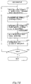
5B ist ein Flussdiagramm, das die Prozedur eines automatischen Belichtungssteuerungsverfahrens zeigt. 5B Fig. 11 is a flowchart showing the procedure of an automatic exposure control method.
-
6 ist eine Außenansicht eines medizinischen, digitalen Röntgenbild-Aufnahmegeräts, das Panorama-Radiografie ausführen kann, wenn die Erfindung angewandt wird. 6 Figure 12 is an exterior view of a medical digital x-ray imaging device that can perform panoramic radiography when the invention is applied.
-
7 ist eine Außenansicht eines Radiografiedetektors, der das medizinische, digitale Röntgenbild-Aufnahmegerät der 6 aufbaut. 7 is an exterior view of a radiography detector using the medical digital x-ray imaging device of the 6 builds up.
-
8 erläutert den Innenaufbau des Radiografiedetektors der 7. 8th explains the internal structure of the radiography detector 7 .
-
9 ist ein Blockdiagramm, das die Struktur eines Steuerungsteils eines Hauptkörpers zeigt, der das medizinische, digitale Röntgenbild-Aufnahmegerät der 6 aufbaut. 9 FIG. 12 is a block diagram showing the structure of a control part of a main body that the medical digital X-ray image recording device of FIG 6 builds up.
-
10 ist ein Blockdiagramm, das die Struktur eines Radiografiedetektors zeigt, der das medizinische, digitale Röntgenbild-Aufnahmegerät der 6 aufbaut. 10th FIG. 12 is a block diagram showing the structure of a radiography detector that incorporates the medical digital X-ray image acquisition device of FIG 6 builds up.
-
11 zeigt die Struktur einer Festkörper-Bilderfassungsvorrichtung in der 9. 11 shows the structure of a solid-state image capturing device in FIG 9 .
-
12 ist ein Panorama-Röntgentransmissionsbild, das durch das medizinische, digitale Röntgenbild-Aufnahmegerät der 6 erhalten wurde. 12th is a panoramic x-ray transmission image created by the medical digital x-ray imaging device 6 was obtained.
-
13 ist eine Außenansicht eines medizinischen, digitalen Röntgenbild-Aufnahmegeräts, das Cephalometrie-Radiografie ausführen kann, wenn die Erfindung angewandt wird. 13 Figure 12 is an exterior view of a medical digital x-ray imaging device that can perform cephalometric radiography when the invention is applied.
-
14 zeigt die Positionsbeziehung zwischen einem Röntgenstrahlungsgenerator, einem zu untersuchenden Objekt und einem Radiografiedetektor für den Fall von Cephalometrie- Radiografie. 14 shows the positional relationship between an X-ray generator, one to examining object and a radiography detector in the case of cephalometric radiography.
-
15 ist ein Blockdiagramm, das die Struktur eines medizinischen, digitalen Röntgenbild-Aufnahmegeräts zeigt, das Linearscan-Radiografie ausführen kann, wenn die Erfindung angewandt wird. 15 Fig. 12 is a block diagram showing the structure of a medical digital X-ray imaging device that can perform linear scan radiography when the invention is applied.
-
16 zeigt einen wesentlichen Teil einer Positionserfassungseinrichtung, die das medizinische, digitale Röntgenbild-Aufnahmegerät der 15 aufbaut. 16 shows an essential part of a position detection device that the medical, digital X-ray image recording device 15 builds up.
-
17 zeigt, wie ein medizinisches, digitales Röntgenbild-Aufnahmegerät, das Dental-Radiografie ausführen kann, genutzt wird, wenn die Erfindung angewandt wird. 17th shows how a medical digital X-ray imaging device that can perform dental radiography is used when the invention is applied.
-
18 ist eine Schnittansicht eines Radiografiedetektors, der das medizinische, digitale Röntgenbild-Aufnahmegerät der 15 aufbaut. 18th is a sectional view of a radiography detector using the medical digital X-ray imaging device of the 15 builds up.
DETAILLIERTE BESCHREIBUNG DER ERFINDUNGDETAILED DESCRIPTION OF THE INVENTION
Nachfolgend werden das automatische Belichtungssteuerungsverfahren für ein Radiografiebild und ein praxisgerechtes medizinisches, digitales Röntgenbild-Aufnahmegerät unter Verwendung dieses Verfahrens erläutert.The automatic exposure control method for a radiographic image and a practical medical digital X-ray image recording device using this method are explained below.
[Ausführungsform 1]Embodiment 1
Die 1 erläutert den Grundaufbau der erfindungsgemäßen automatischen Belichtungssteuerungsvorrichtung. Die automatische Belichtungssteuerungsvorrichtung A1 verfügt über eine Festkörper-Bilderfassungsvorrichtung 1a, wie einen CCD-Sensor, der dem von einer Strahlungslichtquelle 7 abgestrahlten Licht, das durch ein Objekt H gestrahlt wird, von dem ein Bild aufzunehmen ist, ausgesetzt ist, eine Steuerungsverarbeitungseinrichtung 2 und eine Strahlungsquelle-Steuerungseinrichtung 20d. Die Festkörper-Bilderfassungsvorrichtung 1a wird durch ein Treibertaktsignal einer Bilderfassungsvorrichtungs-Treiberschaltung 11d angesteuert, die aus einem TDI(Time Delay Integration)-Taktsignal ein Treibertaktsignal erzeugt, mit Unterteilung in ein Bildelement-Erzeugungsteil 1aa, ein Dunkelstrom-Messteil 1ab und ein Übertragungsteil 1ac für gespeicherte Ladungen.The 1 explains the basic structure of the automatic exposure control device according to the invention. The automatic exposure control device A1 has a solid state imaging device 1a , like a CCD sensor from a radiation light source 7 light emitted by an object H is irradiated, from which an image is to be taken is exposed, a control processing device 2nd and a radiation source controller 20d . The solid-state image capture device 1a is driven by a driver clock signal of an image pickup driver circuit 11d driven, which generates a driver clock signal from a TDI (Time Delay Integration) clock signal, with division into a picture element generating part 1aa, a dark current measuring part 1ab and a transmission part 1ac for stored loads.
Im Bildelement-Erzeugungsteil 1aa ist ein CCD mit Spaltenaufbau vorhanden, das die durch Licht (Röntgenstrahlung usw.) hoher Energie erzeugte elektrische Ladung lädt und überträgt. Auch sind im Dunkelstrom-Messteil 1ab einzelne oder mehrere CCD-Spalten, wie im Bildelement-Erzeugungsteil 1aa, angeordnet. Jedoch ist das CCD im Dunkelstrom-Messteil 1ab maskiert (Röntgenstrahlung wird ausgeblendet), um nicht immer Licht ausgesetzt zu sein. Im Übertragungsteil 1ac für gespeicherte Ladungen ist ein CCD mit Spaltenaufbau zum Übertragen der von jeder Spalte im Bildelement-Erzeugungsteil 1aa und im Dunkelstrom-Messteil 1ab ausgegebenen elektrischen Ladung vorhanden. Die Signale von gespeicherten Ladungen vom Bildelement-Erzeugungsteil 1aa sowie die Dunkelstrom-Messsignale vom Dunkelstrom-Messteil 1ab werden an einem Auslass unten rechts mit einem festen Timing sequenziell in die Steuerungsverarbeitungseinrichtung 2 ausgegeben.In the picture element generation part 1aa there is a CCD with a column structure that charges and transfers the electrical charge generated by light (X-rays, etc.) of high energy. Also in the dark current measuring section 1ab single or multiple CCD columns, as in the picture element generation part 1aa, arranged. However, the CCD is in the dark current measuring section 1ab masked (X-rays are hidden) so that they are not always exposed to light. In the transmission part 1ac for stored loads is a CCD with a column structure for transferring that of each column in the picture element generating part 1aa and in the dark current measuring section 1ab output electrical charge present. The signals of stored charges from the picture element generating part 1aa as well as the dark current measurement signals from the dark current measurement part 1ab are sequentially fed into the control processing device at an outlet at the bottom right with a fixed timing 2nd spent.
Im Bildelement-Erzeugungsteil 1aa ist ein zu beachtendes Pixelelement 1ag eingetragen, um eine automatische Belichtungssteuerung auszuführen. Das zu beachtende Pixelelement 1ag kann sich an einer wahlfreien Position im Bildelement- Erzeugungsteil 1aa befinden, jedoch ist es vorzugsweise im interessierenden Gebiet des Objekts, von dem ein Bild zu erzeugen ist, eingestellt, wo die Lichtempfangsmenge sich während eines Radiografievorgangs nicht stark ändert. Im Fall dentaler Panorama-Radiografie wird es am bevorzugtesten etwas über dem Oberkiefer eingestellt. Die erfindungsgemäße automatische Belichtungssteuerung wird auf Grundlage der Belichtungsmesssignale ausgeführt, bei denen die Dunkelstromkomponente aus den Signalen von gespeicherten Ladungen des zu beachtenden Pixelelements 1ag entfernt ist. Für die Anzahl der zu beachtenden Pixelelemente 1ag besteht keine Beschränkung auf eines, wenn jedoch mehr als zwei zu beachtende Pixelelemente 1ag vorhanden sind, wird ihr Mittelwert als Belichtungsmesssignale verwendet.In the picture element generation part 1aa is a pixel element to be considered 1st day entered to perform automatic exposure control. The pixel element to be considered 1st day can be at an optional position in the picture element generating part 1aa located, however, it is preferably set in the area of interest of the object from which an image is to be formed, where the amount of light reception does not change much during a radiography process. In the case of dental panoramic radiography, it is most preferably set slightly above the upper jaw. The automatic exposure control according to the invention is carried out on the basis of the exposure measurement signals in which the dark current component consists of the signals of stored charges of the pixel element to be observed 1st day is removed. For the number of pixel elements to be considered 1st day there is no restriction to one, but if there are more than two pixel elements to be considered 1st day are present, their mean value is used as exposure measurement signals.
Die Steuerungsverarbeitungseinrichtung 2 entfernt die Dunkelstromkomponente aus den Signalen von gespeicherten Ladungen, wie sie während eines Radiografievorgangs dem Bildelement-Erzeugungsteil 1aa entnommen werden. Andererseits führt sie eine Regelung einer Röntgenstrahlungsquelle-Steuerungseinrichtung aus. Die Steuerungsverarbeitungseinrichtung 2 besteht aus einem Entnahmeteil 2a für das Dunkelstrom-Messsignal zum Entnehmen von Dunkelstrom-Messsignalen aus den Signalen von gespeicherten Ladungen, wie sie von einem Bildsensor 1 vom Bildspeicherungstyp ausgegeben werden, was mit einem vorbestimmten Timing erfolgt, einem Entnahmeteil 2d für das zu beachtende Pixelelement zum Entnehmen der Signale von gespeicherten Ladungen betreffend das zu beachtende Pixelelement mit einem vorbestimmten Timing, einem Belichtungssteuerungssignal-Erzeugungsteil 2b zum Erhalten der Belichtungssteuerungssignale, für die die Dunkelstromkomponente in den vom zu beachtenden Pixelelement 1ag ausgegebenen Signalen von gespeicherten Ladungen unter Bezugnahme auf Parameter, die später beschrieben werden und in einer Dunkelstrom-Kompensationstabelle 3 aufgezeichnet sind, pro vom zu beachtenden Pixelelement 1ag ausgegebenen Signalen von gespeicherten Ladungen und auf Grundlage der vom Dunkelstrom-Messteil 1ab ausgegebenen Dunkelstrom-Messsignale abgeschätzt und berechnet werden, und einen Strahlungsintensitäts-Berechnungsteil 2f zum Ausgeben von Signalen, die die von der Radiografielichtquelle 7 zu emittierende Strahlungslichtqualität auf Grundlage der Belichtungssteuerungssignale berechnet und die Signale zur Regelung der Strahlungsquelle-Steuerungseinrichtung ausgibt.The control processing device 2nd removes the dark current component from the signals of stored charges such as the picture element generating part during a radiography process 1aa be removed. On the other hand, it performs control of an X-ray source control device. The control processing device 2nd consists of a withdrawal part 2a for the dark current measurement signal for taking dark current measurement signals from the signals of stored charges, such as those from an image sensor 1 of the image storage type, which is done at a predetermined timing, a pickup part 2d for the pixel element to be observed for extracting the signals from stored charges relating to the pixel element to be observed with a predetermined timing, an exposure control signal generating part 2 B for obtaining the exposure control signals for which the dark current component is in the pixel element to be observed 1st day output signals of stored charges with reference to parameters to be described later and in a dark current compensation table 3rd are recorded, per pixel element to be observed 1st day output signals of stored charges and based on that from the dark current measuring part 1ab Output dark current measurement signals are estimated and calculated, and a radiation intensity calculation part 2f to output signals from the radiographic light source 7 Radiation light quality to be emitted is calculated on the basis of the exposure control signals and outputs the signals for regulating the radiation source control device.
Die Dunkelstrom-Kompensationstabelle 3 speichert vorab Parameter zum Abschätzen und Berechnen der Dunkelstromkomponente, zu der es beim elektrischen Laden in jede Spalte im Bildelement-Erzeugungsteil 1aa entsprechend einem vorbestimmten Übertragungskanal, d.h. einem Quer-Übertragungskanal in jeder Spalte und einem Vertikal-Übertragungsspalte im Übertragungskanal 1ac für gespeicherte Ladungen, kommt, und zwar auf Grundlage der im Dunkelstrom-Messteil 1ab gemessenen Dunkelstrom-Messsignale (Dunkelstromkomponente).The dark current compensation table 3rd stores parameters in advance for estimating and calculating the dark current component to which it is charged in each column in the picture element generating part during electrical charging 1aa corresponding to a predetermined transmission channel, ie a cross transmission channel in each column and a vertical transmission column in the transmission channel 1ac for stored charges, based on those in the dark current measuring section 1ab measured dark current measurement signals (dark current component).
Nachfolgend wird das Prinzip der automatischen Belichtungssteuerung durch diese Belichtungssteuerungsvorrichtung erläutert.The principle of automatic exposure control by this exposure control device is explained below.
Wenn die Temperatur bei der Radiografie ξ ist, wird die elektrische Ladung, wie sie sich in allen Spalten angesammelt hat, hinsichtlich jeder Spalte pk (k=n,...,1,0) des Bildelement-Erzeugungsteils 1aa und des Dunkelstrom-Messteils 1ab über den Speicherladung-Übertragungsteil 1ac übertragen und als Signale Os (ρk,ξ) von elektrischen Ladungen und die Dunkelstrom-Messsignale Os (p0,ξ) ausgegeben wird, wobei sie durch die folgende Formel (I) wiedergegeben werden.
mit
- Os : Signal von elektrischen Ladungen
- Osx: Effektives Bildelementsignal auf Grundlage der Belichtung (Signalkomponente auf Grund der Belichtung betreffend das Signal von elektrischen Ladungen)
- Dk : Dunkelstromkomponente des Signals von elektrischen Ladungen
- Of : Offsetkomponente des Signals von elektrischen Ladungen
- p : Spaltenposition
- ξ : Temperatur
If the temperature in radiography ξ is, the electric charge accumulated in all columns becomes pk (k = n, ..., 1.0) of the picture element generating part with respect to each column 1aa and the dark current measuring part 1ab via the storage charge transfer part 1ac transmitted and as signals Os (ρk, ξ) of electrical charges and the dark current measurement signals Os (p0, ξ) is output, being represented by the following formula (I). With - Os: signal of electrical charges
- Osx: effective picture element signal based on the exposure (signal component based on the exposure relating to the signal of electrical charges)
- Dk: Dark current component of the signal of electrical charges
- Of: Offset component of the signal of electrical charges
- p: column position
- ξ: temperature
Andererseits sind, wenn die Festkörper-Bilderfassungsvorrichtung 1a so abgeblendet ist, dass sie nicht belichtet ist, das Signal Os(pk,ξ) von elektrischen Ladungen und das Dunkelstrom-Messsignal Os(p0,ξ) auf dieselbe Weise durch die folgende Formel (II) angegeben.
On the other hand, when the solid-state imaging device 1a is so dimmed that it is not exposed, the signal Os (pk, ξ) of electrical charges and the dark current measurement signal Os (p0, ξ) in the same way indicated by the following formula (II).
Es ist bekannt, dass die Dunkelstromkomponente im Wesentlichen in einem Verhältnis zur Ladungsspeicherzeit T der Festkörper-Bilderfassungsvorrichtung 1a steht, so dass die Dunkelstromkomponente in der Spalte k durch die folgende Formel (III) erhalten wird.
mit
- α: Koeffizient
- T: Speicherzeit
It is known that the dark current component is essentially in relation to the charge storage time T the solid-state imaging device 1a stands so that the dark current component in the column k is obtained by the following formula (III). With - α: coefficient
- T: storage time
Wenn die Ladungsspeicherzeit T auf mehrere Arten variiert wird, werden das Signal Os(pk,ξ) von elektrischen Ladungen und das Dunkelstrom-Messsignal Os(p0,ξ) gemessen, und es wird das Verfahren der kleinsten Quadratsumme angewandt, wobei diese direkten Funktionen geeignet sein können. Jedoch werden, bei einem einfachen Verfahren, diese Signale für zwei Ladungsspeicherzeiten T gemessen, und es kann eine durch diese zwei Punkte verlaufende gerade Linie bestimmt werden.If the charge storage time T The signal is varied in several ways Os (pk, ξ) of electrical charges and the dark current measurement signal Os (p0, ξ) is measured, and the least-squares method is used, and these direct functions may be appropriate. However, in a simple process, these signals are used for two charge storage times T measured, and a straight line running through these two points can be determined.
Ferner wird das Ausgangssignalverhältnis α2 der Dunkelstromkomponente Dk(pk,ξ) in der Spalte k des Bildelement-Erzeugungsteils 1aa und der Dunkelstromkomponente Dk(p0,ξ) des Dunkelstrom-Messteils 1ab für eine vorbestimmte Speicherzeit T erhalten, wobei es sich um das Neigungsverhältnis des Kurvenbilds des Signals Os(pk,ξ) von elektrischen Ladungen und des Kurvenbilds des Dunkelstrom-Messsignals Os(p0,ξ) wie folgt handelt:
Furthermore, the output signal ratio α2 the dark current component Dk (pk, ξ) in the column k of the picture element generating part 1aa and the dark current component Dk (p0, ξ) of the dark current measuring part 1ab for a predetermined storage time T obtained, which is the slope ratio of the graph of the signal Os (pk, ξ) of electrical charges and the graph of the dark current measurement signal Os (p0, ξ) acts as follows:
Dabei wird angenommen, dass das Ausgangssignalverhältnis α(pk,ξ) in Teile unterteilt wird, die vom Ort pk und der Temperatur ξ abhängen:
It is assumed that the output signal ratio α (pk, ξ) is divided into parts by the location pk and the temperature ξ depend:
Demgemäß hängt das Ausgangssignalverhältnis α2 nicht von der Temperatur ξ ab, und es wird die folgende Formel (IV) erhalten.
Accordingly, the output signal ratio depends α2 not by temperature ξ and the following formula (IV) is obtained.
Gemäß den Formeln (I) und (IV) wird das effektive Bildelementsignal Osx(pk,ξ) auf Grundlage der Belichtung jeder Spalte pk (k=n,...,1) im Bildelement-Erzeugungsteil 1aa durch das Dunkelstrom-Messsignal Os(p0,ξ) wie folgt ausgedrückt, wenn die Temperatur während der Radiografie ξ ist.
According to formulas (I) and (IV), the effective picture element signal Osx (pk, ξ) based on the exposure of each column pk (k = n, ..., 1) in the picture element generating part 1aa through the dark current measurement signal Os (p0, ξ) expressed as follows if the temperature during radiography ξ is.
Wie es aus der Formel (V) ersichtlich ist, können, wenn das Signal Os(pg,ξ) von gespeicherten Ladungen eines zu beachtenden Pixelelements 1ag während eines Radiografievorgangs durch das Dunkelstrom-Messsignal Os(p0,ξ) des Dunkelstrom-Messteils 1ab gemäß der Formel (V) kompensiert wird, Belichtungsmesssignale erhalten werden, aus denen die Dunkelstromkomponente beseitigt ist.As can be seen from formula (V), when the signal Os (pg, ξ) of stored charges of a pixel element to be observed 1st day during a radiography process using the dark current measurement signal Os (p0, ξ) of the dark current measuring part 1ab is compensated according to the formula (V), exposure measurement signals are obtained from which the dark current component is eliminated.
Das heißt, dass, gemäß der Erfindung, der Entnahmeteil 2d für das zu beachtende Pixelelement die Belichtungsmesssignale Os(pg,ξ) aus den vom zu beachtenden Pixelelement 1ag ausgegebenen Signalen von gespeicherten Ladungen mit einem vorbestimmten Timing entnimmt und der Belichtungssteuerungssignal-Erzeugungsteil 2b die Belichtungssteuerungssignale X gemäß der folgenden Formel berechnet.
mit
- X : Belichtungssteuerungssignal
- pg: Position des zu beachtenden Pixelelements 1ag
That is, according to the invention, the extraction part 2d for the pixel element to be observed, the exposure measurement signals Os (pg, ξ) from the pixel element to be observed 1st day outputs output signals of stored charges at a predetermined timing and the exposure control signal generating part 2 B the exposure control signals X calculated according to the following formula. With - X: Exposure control signal
- pg: position of the pixel element 1ag to be observed
Hierbei ist Of(pg) aus der Formel (VI) weggelassen, das es sich um eine konstante Zahl handelt.Here is Of (pg) omitted from formula (VI) that it is a constant number.
Der Strahlungsintensitäts-Berechnungsteil 2f berechnet die Intensität des zu emittierenden Strahlungslichts entsprechend der folgenden Formel, und er führt eine Regelung der Strahlungsquelle-Steuerungseinrichtung aus, um dadurch eine automatische Belichtungssteuerung zu bewerkstelligen.
mit
- I: Treiberstrom der Strahlungslichtquelle, wie er in der Strahlungsquelle-Steuerungseinrichtung zu erzeugen ist
- A, B: Konstanter Wert
The radiation intensity calculation part 2f calculates the intensity of the radiation light to be emitted according to the following formula, and performs control of the radiation source controller to thereby perform automatic exposure control. With - I: Driving current of the radiation light source as it is to be generated in the radiation source control device
- A, B: constant value
Anstatt den Treiberstrom der Strahlungslichtquelle zu steuern, kann die Treiberspannung auf ähnliche Weise gesteuert werden, es können sowohl der Treiberstrom als auch die Treiberspannung gesteuert werden, oder es kann die Scangeschwindigkeit an Stelle des Treiberstroms gesteuert werden. Wenn der Treiberstrom oder die Scangeschwindigkeit gesteuert wird, wird die Röntgenstrahlungs-Transmissionsmenge insgesamt verändert, und es verändert sich die Helligkeit des erhaltenen Röntgenbilds. Wenn die Treiberspannung gesteuert wird, ändert sich die Energieverteilung der durchgelassenen Röntgenstrahlung, so dass sich der Kontrast des erhaltenen Röntgenbilds ändert.Instead of controlling the driving current of the radiation light source, the driving voltage can be controlled in a similar manner, both the driving current and the driving voltage can be controlled, or the scanning speed can be controlled instead of the driving current. When the driving current or the scanning speed is controlled, the total amount of X-ray transmission is changed and the brightness of the obtained X-ray image changes. When the driving voltage is controlled, the energy distribution of the transmitted X-ray radiation changes, so that the contrast of the X-ray image obtained changes.
Das Prinzip der oben angegebenen automatischen Belichtungssteuerung wird unter Bezugnahme auf die 2 für den Fall von Panorama-Radiografie und den Fall normaler Röntgentransmissions-Radiografie durch eine Festkörper-Bilderfassungsvorrichtung 1a mit MOS-Sensor weiter erläutert.The principle of the automatic exposure control specified above is explained with reference to the 2nd for the case of panoramic radiography and the case of normal X-ray transmission radiography by a solid-state image acquisition device 1a further explained with MOS sensor.
Die 2A zeigt die Beziehung zwischen der Zeit und dem ausgegebenen elektrischen Fall für den Fall einer dentalen Panorama-Radiografie, wobei die von jeder Spalte der Festkörper-Bilderfassungsvorrichtung 1a mit CCD-Sensor ausgegebenen Signale von gespeicherten Ladungen (eindimensional) in einer Radiografie-Zeitserie angeordnet sind. In der Figur (i) ist die Position eines speziellen Pixelelements, d.h. des zu beachtenden Pixelelements 1ag im Bildelement-Erzeugungsteil 1aa mit dem Bezugszeichen pg dargestellt, und die Position des Dunkelstrom-Messteils 1ab ist mit dem Bezugszeichen p0 dargestellt. Die Figur (ii) zeigt das Dunkelstrom-Messsignal (Dunkelstromkomponente) Dk(p0) vom Dunkelstrom-Messteil 1ab. Sie zeigt das Dunkelstrom- Messsignal im Dunkelstrom-Messteil 1ab, wenn eine Röntgenpanorama-Radiografie vorab, vor dem Fabrikversand, ausgeführt wird. Die Figur (ii) zeigt das Signal Os(pg) von gespeicherten Ladungen vom zu beachtenden Pixelelement 1ag für den Fall eines tatsächlichen Radiografievorgangs sowie die in ihm enthaltene Dunkelstromkomponente Dk(pg).The 2A shows the relationship between the time and the output electrical case in the case of a dental panoramic radiography, which is from each column of the solid-state imaging device 1a signals of stored charges (one-dimensional) output with a CCD sensor are arranged in a radiography time series. In the figure (i) is the position of a special pixel element, ie the pixel element to be observed 1st day in the picture element generating part 1aa with the reference symbol pg, and the position of the dark current measuring part 1ab is shown with the reference symbol p0. Figure (ii) shows the dark current measurement signal (dark current component) Dk (p0) from the dark current measuring part 1ab. It shows the dark current measurement signal in the dark current measurement section 1ab, if an X-ray panoramic radiography is carried out in advance, before the factory dispatch. Figure (ii) shows the signal Os (pg) of stored loads from to observing pixel element 1st day for the case of an actual radiography process and the dark current component contained in it Dk (pg) .
Wie es aus den Fig. (ii) und (iii) erkennbar ist, wird dann, wenn Panorama-Radiografie von einem Backenzahn über die Schneidezähne zu einem anderen Backenzahn eines zu untersuchenden Objekts auszuführen ist, die Scangeschwindigkeit bei der Panorama-Radiografie für den Schneidezahn im Allgemeinen verringert, um die Röntgenstrahlungsmenge zu erhöhen, und die Röntgenstrahlungsabsorption in der Halswirbelsäule wird kompensiert. In einem solchen Fall nimmt die Dunkelstromkomponente Dk(pg) entsprechend der Scangeschwindigkeit zu. Jedoch ist das Ausgangssignalverhältnis des Dunkelstrom-Messteils 1ab und der Dunkelstromkomponente des zu beachtenden Pixelelements 1ag unabhängig von der Variation der Absolutstärke konstant. Das heißt, dass das Ausgangssignalverhältnis b/a in den Figuren konstant ist.As can be seen from FIGS. (Ii) and (iii), when panoramic radiography is to be performed from one molar tooth over the incisors to another molar tooth of an object to be examined, the scan speed in the panorama radiography for the incisor becomes generally reduced to increase the amount of x-rays and the x-ray absorption in the cervical spine is compensated for. In such a case, the dark current component Dk (pg) increases according to the scanning speed. However, the output signal ratio of the dark current measuring part is 1ab and the dark current component of the pixel element to be observed 1st day constant regardless of the variation in absolute strength. That is, the output signal ratio b / a is constant in the figures.
Demgemäß wird das Ausgangssignalverhältnis der Dunkelstromkomponente des Dunkelstrom-Messteils 1ab und des zu beachtenden Pixelelements 1ag für eine vorbestimmte Belichtungszeit vorab in der Dunkelstrom-Kompensationstabelle 3 abgespeichert, und die Dunkelstromkomponente Dk(pg) kann dadurch abgeschätzt und berechnet werden, dass das entsprechende Ausgangssignalverhältnis für das Signal Os(pg) von gespeicherten Ladungen angewandt wird, das im Radiografiefall dem zu beachtenden Pixelelement 1ag entnommen wird. Daher können Belichtungsmesssignale berechnet werden, bei denen die Dunkelstromkomponente Dk(pg) aus den Signalen Os(pg) von gespeicherten Ladungen entfernt ist und die automatische Belichtungssteuerung auf Grundlage der berechneten Signale erfolgt.Accordingly, the output signal ratio of the dark current component of the dark current measuring part 1ab and the pixel element to be observed 1st day for a predetermined exposure time in advance in the dark current compensation table 3rd stored, and the dark current component Dk (pg) can be estimated and calculated by the corresponding output signal ratio for the signal Os (pg) of stored charges is applied, which in the case of radiography is the pixel element to be observed 1st day is removed. Exposure measurement signals can therefore be calculated in which the dark current component Dk (pg) from the signals Os (pg) is removed from stored loads and the automatic exposure control takes place on the basis of the calculated signals.
Die 2B zeigt die Position pg eines speziellen Pixelelements, d.h. des zu beachtenden Pixelelements 1ag, und die Position p0 des Dunkelstrom-Messteils 1ab im Bild, wobei das von der Festkörper-Bilderfassungsvorrichtung 1a mit MOS- Sensor ausgegebene Signal Os(pk) von gespeicherten Ladungen entsprechend der Position des Pixelelements „e“ zweidimensional angeordnet ist. Die 2B ist ein Diagramm, das die Beziehung zwischen der Dunkelstromkomponente Dk(pg) an der Position des zu beachtenden Pixelelements 1ag, der Dunkelstromkomponente Dk(p0) an der Position des Dunkelstrom- Messteils 1ab und der Belichtungszeit T zeigt.The 2 B shows the position pg a special pixel element, ie the pixel element to be observed 1 day, and the position p0 of the dark current measuring part 1ab in the picture, which is from the solid-state imaging device 1a signal output with MOS sensor Os (pk) of stored charges according to the position of the pixel element " e “Is arranged two-dimensionally. The 2 B is a graph showing the relationship between the dark current component Dk (pg) at the position of the pixel element to be observed 1 day, the dark current component Dk (p0) at the position of the dark current measuring part 1ab and the exposure time T shows.
Wie es im Kurvenbild dargestellt ist, ist das Steigungsverhältnis der Ausgangssignaländerung des Signals Ok(pk) von gespeicherten Ladungen des zu beachtenden Pixelelements 1ag für die Belichtungszeit T und der Ausgangssignaländerung des Signals Dk(p0) von gespeicherten Ladungen des Pixelelements oder mindestens einer Pixelelementspalte im Dunkelstrom-Messteil 1ab für die Belichtungszeit T im Wesentlichen konstant. Daher wird, wenn das Steigungsverhältnis dieser Ausgangssignaländerungen vorab in der Dunkelstrom-Kompensationstabelle 3 entsprechend jedem Pixelelement oder jeder Pixelelementspalte im Bildelement-Erzeugungsteil 1aa abgespeichert wird, die entsprechende Steigung der Ausgangssignaländerung am Signal Ok(pg) von gespeicherten Ladungen angewandt, wie es im Radiografiefall dem zu beachtenden Pixelelement 1ag entnommen wird, und die Dunkelstromkomponente Dk(pk) kann entsprechend dem aktuellen Radiografiezeitpunkt abgeschätzt und berechnet werden. Daher werden Belichtungsmesssignale, aus denen die Dunkelstromkomponente Dk(pg) entfernt ist, berechnet, und die automatische Belichtungssteuerung wird auf Grundlage der berechneten Signale ausgeführt.As shown in the graph, the slope ratio is the output signal change of the signal OK ( pk ) of stored charges of the pixel element to be observed 1st day for the exposure time T and the output signal change of the signal Dk (p0) of stored charges of the pixel element or at least one pixel element column in the dark current measuring part 1ab for the exposure time T essentially constant. Therefore, if the slope ratio of these output signal changes is previously in the dark current compensation table 3rd corresponding to each pixel element or column of pixel elements in the picture element generating part 1aa is saved, the corresponding slope of the output signal change on the signal OK (pg) of stored charges applied, as is the case with the pixel element to be observed in the radiography case 1st day is taken, and the dark current component Dk ( pk ) can be estimated and calculated according to the current time of radiography. Therefore, exposure measurement signals that make up the dark current component Dk (pg) is calculated, and the automatic exposure control is carried out based on the calculated signals.
Die 3 zeigt ein Beispiel der Dunkelstrom-Kompensationstabelle 3. In der Figur kennzeichnet α2 (pk=1, ... , n) das Ausgangssignalverhältnis α2 in einer vorbestimmten Belichtungszeit für das Dunkelstrom-Messsignal jeder Spalte (k=1,...,n) im Bildelement-Erzeugungsteil 1aa. Wenn das Ausgangssignalverhältnis für jede Spalte gespeichert wird, kann das zu beachtende Pixelelement 1ag an einer wahlfreien Position im Bildelement-Erzeugungsteil 1aa eingestellt werden.The 3rd shows an example of the dark current compensation table 3rd . Features in the figure α2 (pk = 1, ..., n) the output signal ratio α2 in a predetermined exposure time for the dark current measurement signal of each column (k = 1, ..., n) in the picture element generating part 1aa. If the output signal ratio is saved for each column, the pixel element to be considered can 1st day at an optional position in the picture element generating part 1aa can be set.
Nun werden die Betriebsabläufe der Regelung der Steuerungsverarbeitungseinrichtung 2 für den Treiberstrom I unter Bezugnahme auf die beigefügte Figur erläutert.Now the operating procedures of the regulation of the control processing device 2nd for the driver current I explained with reference to the accompanying figure.
Die 4 ist ein Kurvenbild, das die Beziehung zwischen den Belichtungssteuerungssignalen X und dem Treiberstrom I zeigt. Diese Erläuterung ist qualitativ, und die Koordinate und die Steigung im Kurvenbild sind beliebig. In der Figur kennzeichnet die Linie M die oben genannte Formel (VII) I=- AX+B (X ist das Belichtungssteuerungssignal, A,B bilden jeweils einen beliebigen, konstanten Wert). Diese Regelung wird so ausgeführt, dass der Stärkewert, der dadurch gebildet wird, dass die in einem speziellen Pixelelement oder einer speziellen Pixelelementspalte im Dunkelstrom-Messteil der Bilderfassungsvorrichtung gespeicherten Ladungssignale aus den Ladungssignalen entfernt werden, die in einem speziellen Pixelelement oder einer speziellen Pixelelementspalte im Bildelement-Erzeugungsteil der Bilderfassungsvorrichtung gespeichert werden, innerhalb eines vorbestimmten Dichtebereichs gehalten wird. Der Treiberstrom I ist eine Funktion der Belichtungssteuerungssignale X, und er ist durch eine gerade Linie wiedergegeben, jedoch handelt es sich tatsächlich um eine monoton ansteigende Funktion, und es kann sich um eine gekrümmte Linie handeln. Hierbei kann der Treiberstrom I im Fall einer Röntgenstrahlungssteuerung ein Röhrenstrom oder eine Röhrenspannung sein. Ferner kann es sich um die Scangeschwindigkeit oder den Gradationsprozess oder eine Kombination hiervon handeln.The 4th Fig. 10 is a graph showing the relationship between the exposure control signals X and the driver current I. shows. This explanation is qualitative, and the coordinate and the slope in the graph are arbitrary. In the figure, the line M denotes the formula (VII) I = - AX + B ( X is the exposure control signal, A , B each form an arbitrary, constant value). This control is carried out in such a way that the strength value, which is formed by removing the charge signals stored in a special pixel element or a special pixel element column in the dark current measuring part of the image capturing device from the charge signals which are in a special pixel element or a special pixel element column in the picture element Generation part of the image capturing device can be stored within a predetermined density range. The driver current I. is a function of the exposure control signals X , and it is represented by a straight line, but it is actually a monotonically increasing function and it can be a curved line. Here, the driver current I. in the case of X-ray control, a tube current or be a tube voltage. It can also be the scanning speed or the gradation process or a combination thereof.
Es ist zu beachten, dass dann, wenn der Treiberstrom I erhöht wird, der Wert des Signals Os(pk,ξ) von gespeicherten Ladungen im Bildelement-Erzeugungsteil 1aa insgesamt erhöht wird und im Ergebnis das Signal Os(pg,ξ) von gespeicherten Ladungen des zu beachtenden Pixelelements erhöht ist. Jedoch ändert sich das Dunkelstrom-Messsignal Os(p0,ξ) nicht, da die Speicherzeit T nicht geändert wird.It should be noted that if the driver current I. is increased, the value of the signal Os (pk, ξ) of stored charges in the picture element generating part 1aa overall is increased and as a result the signal Os (pg, ξ) of stored charges of the pixel element to be observed is increased. However, the dark current measurement signal changes Os (p0, ξ) not because of the storage time T is not changed.
Wenn in der 4 der Wert „x“ des Belichtungssteuerungssignals X bei einem tatsächlichen Radiografievorgang der Punkt m1 auf der Linie M ist, wird die Steuerung so ausgeführt, dass auf den Punkt m2 der Belichtungssteuerungs-Sollsignale x0 abgezielt wird.If in the 4th the value " x “Of the exposure control signal X the point in an actual radiography process m1 on the line M the control is carried out so that to the point m2 the exposure control target signals x0 is targeted.
Wenn die Signale von gespeicherten Ladungen des zu beachtenden Pixelelements außerhalb des Regelungs-Sollwerts liegen und sie prompt auf diesen konvergieren, kommt es in diesem Teil zu dunklen und hellen Streifen im Vergleich zu den anderen Teilen.If the signals from stored charges of the pixel element to be observed lie outside the control setpoint value and they converge promptly thereon, dark and light stripes appear in this part in comparison to the other parts.
Ein derartiges Problem kann dadurch gelöst werden, dass ein vorbestimmtes Verzögerungselement zur Regelung hinzugefügt wird und dem Regelungs-Sollwert langsam nachgefahren wird (Wirkung als Tiefpassfilter). In der Praxis kann ein Tiefpassfilter aus einem Kondensator und einem Widerstand angebracht werden, oder ein Vergangenheitswert wird mit einem Zeitgewichtungsfaktor gewichtet, um dann zum aktuellen Wert addiert zu werden.Such a problem can be solved by adding a predetermined delay element to the control and slowly following the control setpoint (effect as a low-pass filter). In practice, a low-pass filter consisting of a capacitor and a resistor can be attached, or a past value is weighted with a time weighting factor and then added to the current value.
Als Nächstes werden entsprechend Flussdiagrammen schematische Prozeduren zum Erzeugen der Dunkelstrom-Kompensationstabelle und der automatischen Belichtungssteuerung erläutert.Next, according to flowcharts, schematic procedures for generating the dark current compensation table and the automatic exposure control will be explained.
Die 5A zeigt, wie die Dunkelstrom-Kompensationstabelle 3 vor einem tatsächlichen Radiografievorgang erzeugt wird, z. B. vor dem Fabrikversand. In einem Schritt 201 wird die Festkörper-Bilderfassungsvorrichtung 1a völlig abgewendet, und das Signal Os(pg) von gespeicherten Ladungen für das gesamte Pixelelement einschließlich des Dunkelstrom- Messteils 1ab wird für mehrere Speicherzeiten T gemessen. In einem Schritt 202 wird aus dem Messergebnis die Beziehung zwischen der Speicherzeit T und dem Signal Os(pg) von gespeicherten Ladungen für das gesamte Pixelelement erhalten. Dann wird in einem Schritt 203 das Ausgangssignalverhältnis α2 der Dunkelstromkomponente für eine vorbestimmte Belichtungszeit vom Dunkelstrom-Messteil 1ab und jedes Pixelelement oder jede Pixelelementspalte im Bildelement-Erzeugungsteil 1aa aus der erhaltenen Beziehung der Speicherzeit T und des Signals Os(pg) von gespeicherten Ladungen für das gesamte Pixelelement erhalten. Schließlich werden in einem Schritt 204 das Ausgangssignalverhältnis α2 und der Offset Of in der Dunkelstrom-Kompensationstabelle 3 für das gesamte Pixelelement gespeichert. Die Dunkelstrom-Kompensationstabelle 3 wird, falls erforderlich, für mehrere Speicherzeitarten gespeichert, wobei die Temperatur variiert ist.The 5A shows how the dark current compensation table 3rd is generated before an actual radiography process, e.g. B. before the factory shipment. In one step 201 becomes the solid-state imaging device 1a completely averted, and the signal Os (pg) of stored charges for the entire pixel element including the dark current measuring part 1ab is for multiple storage times T measured. In one step 202 the result of the measurement becomes the relationship between the storage time T and the signal Os (pg) obtained from stored charges for the entire pixel element. Then in one step 203 the output signal ratio α2 of the dark current component for a predetermined exposure time from the dark current measuring part 1ab and each pixel element or column of pixel elements in the picture element generating part 1aa from the relationship of the storage time obtained T and the signal Os (pg) obtained from stored charges for the entire pixel element. Finally, in one step 204 the output signal ratio α2 and the offset of in the dark current compensation table 3rd saved for the entire pixel element. The dark current compensation table 3rd is stored for several types of storage times, if necessary, with the temperature varying.
Die 5B zeigt die Prozedur der automatischen Belichtungssteuerung für einen tatsächlichen Radiografievorgang. In einem Schritt 301 wird ein Radiografievorgang ausgeführt, und es werden die gespeicherten Signale Os für jedes Pixelelement ausgegeben. In einem Schritt 302 wird das Dunkelstrom-Messsignal Os(p0) entnommen. Als Nächstes wird in einem Schritt 303 das Signal Os(pg) von gespeicherten Ladungen vom zu beachtenden Pixelelement 1ag entnommen. Das entnommene gespeicherte Signal Os(pg) des zu beachtenden Pixelelements kann ein Spaltensignal oder mehrere Spaltensignale sein. In einem Schritt 304 wird der in der Dunkelstrom-Kompensationstabelle 3 gespeicherte Wert α2 (pk) auf das Dunkelstrom-Messsignal Os(p0) und das Signal Os(pg) von gespeicherten Ladungen angewandt, um das Belichtungssteuerungssignal X zu berechnen. In einem Schritt 305 wird die Intensität von Strahlungslicht, wobei es sich um den zu regelnden Sollwert handelt, auf Grundlage des Belichtungssteuerungssignals X berechnet, und gleichzeitig mit der Radiografie erfolgt eine Regelung. Im letzten Schritt 306 wird beurteilt, ob der Prozess abgeschlossen ist, und wenn die Prozedur nicht beendet ist, kehrt der Schritt zu 301 zurück. Tatsächlich wird die Dunkelstromkomponente des belichteten Pixelelements aus der Beziehung zwischen dem belichteten Pixelelement und dem unbelichteten Pixelelement für die Ladungsspeicherzeit, wie sie vorab pro Pixelelement in der Kompensationstabelle für den Radiografiefall abgespeichert wurde, und aus der Beziehung zwischen der während eines tatsächlichen Radiografievorgangs gemessenen Radiografiezeit und dem unbelichteten Pixelelement abgeschätzt, und durch die Belichtungssteuerungssignale wird eine Regelung ausgeführt. Für diese Abschätzung werden die Ladungsspeicherzeiten während des Vorprozesses und während eines Radiografievorgangs nicht als Parameter verwendet. Daher ist kein Entnahmeprozess für die Ladungsspeicherzeit erforderlich, so dass Anwendbarkeit besteht, wenn ein TDI- Taktsignalgenerator außerhalb eines Röntgenstrahlungsdetektors vorhanden ist. Bei der Radiografieregelung wird in der Praxis die Röntgenstrahlungs-Scangeschwindigkeit und/oder der Röntgenstrom und/oder die Röntgenröhrenspannung und/oder ein Gradationsprozess oder eine Kombination hiervon gesteuert.The 5B shows the procedure of automatic exposure control for an actual radiography process. In one step 301 a radiography process is performed and the stored signals Os output for each pixel element. In one step 302 becomes the dark current measurement signal Os (p0) taken. Next is one step 303 the signal Os (pg) of stored charges from the pixel element to be observed 1st day taken. The extracted stored signal Os (pg) of the pixel element to be observed can be one column signal or several column signals. In one step 304 becomes the one in the dark current compensation table 3rd stored value α2 ( pk ) to the dark current measurement signal Os ( p0 ) and the signal Os (pg) of stored charges applied to the exposure control signal X to calculate. In one step 305 becomes the intensity of radiation light, which is the target value to be controlled, based on the exposure control signal X calculated, and a regulation takes place simultaneously with the radiography. In the last step 306 it is judged whether the process is completed, and if the procedure is not finished, the step returns 301 back. In fact, the dark current component of the exposed pixel element is determined from the relationship between the exposed pixel element and the unexposed pixel element for the charge storage time as previously stored per pixel element in the radiographic case compensation table, and from the relationship between the radiographic time measured during an actual radiographic process and the unexposed pixel element, and control is performed by the exposure control signals. The charge storage times during the pre-process and during a radiography process are not used as parameters for this estimation. Therefore, no charge storage time extraction process is required, so there is applicability when a TDI clock signal generator is provided outside an X-ray detector. In practice, the radiography control controls the X-ray scanning speed and / or the X-ray current and / or the X-ray tube voltage and / or a gradation process or a combination thereof.
[Ausführungsform 2] Embodiment 2
Als Nächstes wird ein medizinisches, digitales Röntgenbild-Aufnahmegerät erläutert, das eine Panorama-Radiografie ausführen kann, bei der die Erfindung angewandt wird.Next, a medical digital X-ray imaging device that can perform panoramic radiography to which the invention is applied will be explained.
Die 6 zeigt eine Außenansicht des Röntgenbild-Aufnahmegeräts A2. Ein Ständer 4b steht auf einem Sockel 4a eines Gerätekörpers 4, am Ständer 4b ist ein Haltekörper 5 so angebracht, dass er nach oben und unten beweglich ist, und am Haltekörper 5 ist ein Dreharm 6 drehbar vorhanden. Ein sich horizontal erstreckender Haltearm 5a ist für das obere Ende des Haltekörpers 5 vorhanden und für sein unteres Ende ist ein Objektrahmen 5b vorhanden. Für den Objektrahmen 5b ist eine Kinnstütze 5c vorhanden.The 6 shows an external view of the X-ray image recording device A2 . A stand 4b stands on a pedestal 4a of a device body 4th , on the stand 4b is a holding body 5 attached so that it can be moved up and down, and on the holding body 5 is a swivel arm 6 rotatable available. A horizontally extending arm 5a is for the upper end of the holding body 5 exists and for its lower end there is an object frame 5b available. For the object frame 5b is a chin rest 5c available.
Im Haltearm 5a ist ein XY-Tisch untergebracht, der durch einen Schrittmotor in den Richtungen X und Y verstellbar ist, und der Dreharm 6 kann gedreht werden, während er durch den XY-Tisch gelagert ist, wobei er in der vertikalen Ebene frei beweglich ist. Eine Kopfhalteeinrichtung 5d für ein Objekt ist eine Objekthalteeinrichtung, die an der Unterseite des Haltearms 5a angebracht ist, den Dreharm 6 durchdringt und über einen Positionssteuerungsmechanismus verfügt.In the holding arm 5a An XY table is housed by a stepper motor in the directions X and Y is adjustable, and the swivel arm 6 can be rotated while it is supported by the XY table, being freely movable in the vertical plane. A head restraint 5d for an object is an object holding device, which is on the underside of the holding arm 5a attached, the swivel arm 6 penetrates and has a position control mechanism.
Für den Dreharm 6 ist ein Drehmechanismus vorhanden, um ihn durch einen Schrittmotor in Bezug auf den Haltearm 5a zu drehen. Der Dreharm 6 ist so aufgebaut, dass er sich in Bezug auf eine senkrechte axiale Linie dreht, während das Rotationszentrum durch den oben genannten XY-Tisch verstellt wird. Die beiden Enden des Dreharms 6 hängen nach unten, für ein Ende 6a ist ein Röntgenstrahlungsgenerator 7 vorhanden, und für das andere Ende 6b ist gegenüberstehend ein Röntgenstrahlungs-Erfassungsteil 8 vorhanden. Der Röntgenstrahlungsgenerator 7 verfügt über eine Röntgenstrahlungsröhre, eine Röntgenstrahlungs-Ausblendplatte mit einem ersten Längsschlitz, einen Steuerungsmechanismus zum Ändern der Form des ersten Schlitzes, usw. (diese sind nicht dargestellt).For the swivel arm 6 there is a rotating mechanism to move it through a stepper motor with respect to the support arm 5a to turn. The swivel arm 6 is constructed in such a way that it rotates with respect to a vertical axial line, while the center of rotation is adjusted by the above-mentioned XY table. The two ends of the swivel arm 6 hang down for an end 6a is an X-ray generator 7 present, and for the other end 6b opposite is an X-ray detection part 8th available. The X-ray generator 7 has an X-ray tube, an X-ray blanking plate with a first longitudinal slot, a control mechanism for changing the shape of the first slot, etc. (these are not shown).
Das Röntgenstrahlungs-Erfassungsteil 8 verfügt über einen zweiten Längsschlitz 9a, der dem ersten Schlitz entspricht, und eine Ausblendplatte 9 mit einem Steuerungsmechanismus für den Schlitz 9a, die so vorhanden sind, dass sie dem Röntgenstrahlungsgenerator 7 gegenüberstehen. An der Rückseite der Ausblendplatte 9 ist ein Detektorhalter 10 vorhanden, und am Detektorhalter 10 ist ein Radiografiedetektor 11A vorhanden.The X-ray detection part 8th has a second longitudinal slot 9a , which corresponds to the first slot, and a blanking plate 9 with a control mechanism for the slot 9a that are present so that they are the X-ray generator 7 face each other. At the back of the blanking plate 9 is a detector holder 10th available, and on the detector holder 10th is a radiography detector 11A available.
Hinter dem Röntgenstrahlungs-Erfassungsteil 8 ist ein Steuerungsteil 12 für den Gerätekörper mit einer gedruckten Leiterplatte mit mehreren Schaltkreisen vorhanden, und eine Bedienkonsole 13 ist so vorhanden, dass sie die Außenseite desselben bedeckt. Für die Bedienkonsole 13 sind mehrere Schalter und ein Flüssigkristalldisplay 13a vorhanden (nicht dargestellt).Behind the X-ray detection part 8th is a control part 12th for the device body with a printed circuit board with several circuits, and an operating console 13 is so present that it covers the outside of it. For the control console 13 are several switches and a liquid crystal display 13a available (not shown).
Der Gerätekörper 4 verfügt über ein Fernsteuerungskästchen 14A, das mit einem Bedienungskabel 14a angeschlossen ist, und für das Kästchen 14A sind ein Hauptschalter zum Ein- oder Ausschalten einer Spannungsquelle und ein Röntgenstrahlungsschalter vorhanden.The device body 4th has a remote control box 14A that with an operating cable 14a is connected, and for the box 14A there is a main switch for switching a voltage source on and off and an X-ray switch.
Für den Röntgenstrahlung-Erfassungsteil 8 ist ein Verbinder 15 für Verbindung mit dem Radiografiedetektor vorhanden.For the X-ray detection part 8th is a connector 15 available for connection to the radiography detector.
Die 7 zeigt die Außenansicht des Radiografiedetektors 11A, und die 8 zeigt dessen Innenaufbau. Der Detektor 11A verfügt über eine Festkörper-Bilderfassungsvorrichtungseinheit 1 wie einen CCD-Sensor, und er ist mit einem Außengehäuse 16 verstärkt, das mehrere Arten von Schaltkreisen für die Einheit aufnimmt. Der Verbinder 17 für eine externe Schaltung ist an einer Seite des Gehäuses 16 vorhanden, und er ist allgemein mit einem einheitlichen Kabel mit einer Spannungsversorgungsleitung und einer Signalleitung (nicht dargestellt) mit dem Verbinder 15 des Röntgenstrahlungs-Erfassungsteils 8 verbunden. Der Verbinder 17 kann dazu verwendet werden, externe Geräte wie einen PC anzuschließen.The 7 shows the external view of the radiography detector 11A , and the 8th shows its interior structure. The detector 11A has a solid-state imaging device unit 1 like a CCD sensor, and it's with an outer case 16 amplified, which houses several types of circuitry for the unit. The connector 17th for an external circuit is on one side of the case 16 and is generally with a unitary cable with a power supply line and a signal line (not shown) with the connector 15 of the X-ray detection part 8th connected. The connector 17th can be used to connect external devices like one PC to connect.
Das Außengehäuse 16 besteht aus einem geeigneten Material mit erforderlicher Stabilität, wie Metall, wie einer Aluminiumplatte, oder einem Kunstharz, wie ABS-Harz. Der Röntgenstrahlungs-Erfassungsteil 18, der aus einem Material besteht, das vorzugsweise Röntgenstrahlung durchlässt, jedoch sichtbares Licht ausblendet, z. B. ABS-Harz mit dunkler Farbe, ist in der Längsrichtung im Zentrum der Vorderseite so vorhanden, dass er an der Rückseite des zweiten Schlitzes 9a liegt. Die Festkörper-Bilderfassungsvorrichtungseinheit 1 ist innerhalb des Röntgenstrahlungs-Erfassungsteils 18 vorhanden.The outer case 16 consists of a suitable material with required stability, such as metal, such as an aluminum plate, or a synthetic resin, such as ABS resin. The X-ray detection part 18th , which consists of a material that preferably transmits X-rays, but hides visible light, e.g. B. ABS resin with a dark color is present in the longitudinal direction in the center of the front so that it is at the back of the second slot 9a lies. The solid-state imaging device unit 1 is inside the X-ray detection part 18th available.
Die Festkörper-Bilderfassungsvorrichtungseinheit 1, die an der Rückseite des Röntgenstrahlungs-Erfassungsteils 18 vorhanden ist, besteht aus einem Licht emittierenden Körper 1b (Szintillator) zum Wandeln der abgestrahlten Röntgenstrahlung in sichtbares Licht, einer optischer Faser 1c zum Übertragen des vom Licht emittierenden Körper 1b erzeugten Lichts in die Lichtempfangsfläche der Festkörper-Bilderfassungsvorrichtung 1a, und diese Festkörper-Bilderfassungsvorrichtung 1a, die später erläutert wird, und sie verfügt über eine Leiterplatte 1d. Die Bezugszahl 19 kennzeichnet ein Schutzgehäuse, 19a kennzeichnet ein Abdichtmaterial zum Ausblenden von Röntgenstrahlung, und 1e ist ein Signalstift der Festkörper-Bilderfassungsvorrichtungseinheit 1. Am unteren Teil des Abdichtmaterials 19a ist ein Röntgenstrahlungs-Ausblendmaterial 19b angebracht, das eine Bleiplatte ist, um den später erläuterten Dunkelstrom-Messteil 1ab, der später erläutert wird, am entsprechenden Teil der Festkörper-Bilderfassungsvorrichtung 1a anzubringen, wobei der Licht emittierende Körper 1b gegen Röntgenstrahlung abgeschirmt wird.The solid-state imaging device unit 1 that are on the back of the x-ray detection part 18th exists, consists of a light-emitting body 1b (Scintillator) for converting the emitted X-rays into visible light, an optical fiber 1c to transmit the body emitting light 1b generated light into the light receiving surface of the solid-state imaging device 1a , and this solid-state imaging device 1a , which will be explained later, and it has a circuit board 1d . The reference number 19th indicates a protective housing, 19a denotes a sealing material for masking X-rays, and 1e is a signal pin of the solid state Image capture device unit 1 . On the lower part of the sealing material 19a is an X-ray masking material 19b attached, which is a lead plate around the dark current measuring part explained later 1ab, which will be explained later on the corresponding part of the solid-state image capturing device 1a attach, the light emitting body 1b is shielded against X-rays.
Die schematische Struktur des wesentlichen Teils des Gerätekörpers 4 wird unter Bezugnahme auf die 9 erläutert, und die schematische Struktur des wesentlichen Teils des Festkörper-Bilderfassungsvorrichtungsdetektors 11A wird unter Bezugnahme auf die 10 erläutert.The schematic structure of the essential part of the device body 4th is with reference to the 9 and the schematic structure of the essential part of the solid-state imaging device detector 11A is with reference to the 10th explained.
Die 9 ist ein Blockdiagramm, das die schematische Struktur des wesentlichen Teils des Steuerungsteils 20 des Gerätekörpers zeigt. Der Steuerungsteil 20 verfügt über eine Steuerungseinheit 20a mit einer MPU (CPU), die das Betriebs- und Steuerungszentrum des gesamten Röntgenbild-Aufnahmegeräts A2 bildet, einen Eingangs/Ausgangs-Port 20b und einen Speicher 20c. Außerdem verfügt er über eine Röntgenstrahlungs-Steuerungsschaltung 20d zum Ansteuern und Steuern des Röntgenstrahlungsgenerators 7, eine TDI-Taktsignal-Erzeugungsschaltung 20g, eine Kommunikations-Steuerungsschaltung 20h und eine Spannungsversorgungsschaltung 20i. Dies sind über den Eingangs/Ausgangs-Port 20b mit der Steuerungseinheit 20a verbunden. Mit dem Eingangs/Ausgangs-Port 20b ist eine Bedienkonsole 13 zum Eingeben mehrerer Betriebsdaten oder das Fernsteuerungskästchen 14A zur Ferneingabe der Daten verbunden. Ferner ist ein Verbinder 17 vorhanden, der dem Verbinder 17' eines Anschlusskabels 21 zum Anschließen des Radiografiedetektors 11A entspricht, und der Eingangs/Ausgangs-Port 20b, die Kommunikations-Steuerungsschaltung 20h und die Spannungsversorgungsschaltung 20i sind mit dem Verbinder 17 verbunden.The 9 Fig. 10 is a block diagram showing the schematic structure of the essential part of the control part 20th of the device body shows. The control part 20th has a control unit 20a with an MPU (CPU), which is the operating and control center of the entire X-ray imaging device A2 forms an input / output port 20b and a memory 20c . It also has an X-ray control circuit 20d to control and control the X-ray generator 7 , a TDI clock signal generating circuit 20g , a communication control circuit 20h and a power supply circuit 20i . These are through the input / output port 20b with the control unit 20a connected. With the input / output port 20b is a control console 13 to enter multiple operating data or the remote control box 14A connected for remote data entry. There is also a connector 17th present to the connector 17 ' a connection cable 21 to connect the radiography detector 11A and the input / output port 20b , the communication control circuit 20h and the power supply circuit 20i are with the connector 17th connected.
Die 10 ist ein Blockdiagramm des wesentlichen Teils des Radiografiedetektors 11A. Der Detektor 11A verfügt über eine Steuerungseinheit 11a aus einer MPU (CPU) zum Steuern des Betriebs jeder Schaltung in ihm sowie des Gesamtbetriebs des Röntgenbild-Aufnahmegeräts A2 einschließlich des Gerätekörpers 4 selbst oder gemeinsam mit dem Steuerungsteil 20 des Gerätekörpers, einen Eingangs/Ausgangs-Port 11b, eine TDI-Taktsignal-Wandlerschaltung 11c, eine Bildelement-Treiberschaltung 11d, einen A/D-Wandler 11e, einen Speicher 11f, eine Kommunikations-Steuerungsschaltung 11g und eine Spannungsschaltung 11h. Jede Schaltung und ein Verbinder 17 sind so verbunden, wie es in der Figur dargestellt ist. Die Steuerungseinheit 11a ist so aufgebaut, dass sie für die Funktion der Bildverarbeitungseinrichtung 2 zum Kompensieren eines Dunkelstroms, was bei der Ausführungsform 1 als Charakteristikum der Erfindung erläutert ist, durch einen Softwareprozess sorgt. Die Dunkelstromkompensations-Tabelle 3, auf die die Pixelelement-Verarbeitungseinrichtung Bezug nimmt, wird vor dem Fabrikversand vorab im Speicher 11f abgespeichert und dazu verwendet, ein effektives Pixelelement abzuspeichern, wie es während eines Radiografievorgangs ein Panorama-Röntgenbild erzeugt.The 10th Fig. 3 is a block diagram of the essential part of the radiography detector 11A . The detector 11A has a control unit 11a from one MPU ( CPU ) to control the operation of each circuit in it and the overall operation of the X-ray imaging device A2 including the device body 4th yourself or together with the control part 20th of the device body, an input / output port 11b , a TDI clock signal converter circuit 11c , a picture element driver circuit 11d , an A / D converter 11e, a memory 11f , a communication control circuit 11g and a voltage circuit 11h . Each circuit and a connector 17th are connected as shown in the figure. The control unit 11a is constructed in such a way that it is responsible for the function of the image processing device 2nd to compensate for a dark current, which is in the embodiment 1 is explained as a characteristic of the invention, ensures by a software process. The dark current compensation table 3rd referenced by the pixel element processor is stored in the memory in advance of the factory shipment 11f stored and used to store an effective pixel element as it generates a panoramic x-ray image during a radiography process.
Der Radiografiedetektor 11A ist so aufgebaut, dass er vom Gerätekörper 4 abnehmbar oder fest an ihm anbringbar ist. Zu diesem Zweck ist der Verbinder 17 elektrisch und regelungstechnisch durch einen Verbinder 17', der am vom Steuerungsteil 20 des Hauptkörpers eingeführten Verbindungskabel 21 vorhanden ist, mit dem Steuerungsteil 20 des Gerätekörpers verbunden. Der Steuerungsteil 20 des Gerätekörpers ist so aufgebaut, dass ein externes Gerät 100 wie ein PC so angeschlossen ist, dass Steuerungsinformation in den Steuerungsteil 20 selbst und den Radiografiedetektor 11A eingegeben wird und die Daten ausgegeben und gespeichert werden. Der Speicher 11f, in dem die Dunkelstromkompensations-Tabelle 3 abgespeichert ist, ist bei der oben angegebenen Ausführungsform im Radiografiedetektor 11A vorhanden, jedoch kann der im Computer außerhalb des Gerätekörpers vorhandene Speicher verwendet werden.The radiography detector 11A is constructed so that it is from the device body 4th is removable or firmly attachable to it. For this purpose the connector is 17th electrical and control technology through a connector 17 ' from the control section 20th of the main body inserted connecting cable 21 is present with the control part 20th of the device body connected. The control part 20th of the device body is designed so that an external device 100 as a PC is connected so that control information in the control part 20th itself and the radiography detector 11A is entered and the data is output and saved. The memory 11f in which the dark current compensation table 3rd is stored in the above-mentioned embodiment in the radiography detector 11A available, but the memory available in the computer outside the device body can be used.
Die 11 zeigt eine schematische Struktur der für den Radiografiedetektor 11A vorhandenen Festkörper-Bilderfassungsvorrichtung 1a. Die Festkörper-Bilderfassungsvorrichtung 1a besteht aus einem CCD-Sensor vom FFT-Typ (Full-Frame-Transfer-Typ). Die Bezugszahl 1ad kennzeichnet eine Sensormatrix aus einem Lichtempfangsteil, und sie ist so aufgebaut, dass ein Horizontalschieberegister 1ae zum Übertragen der gespeicherten Ladung in horizontaler Richtung in mehreren nach oben und unten verlaufenden Spalten angeordnet ist und ein in einer Spalte oder einem Schritt angeordnetes Pixelelement „e“ durch die Potenzialwanne gebildet ist, die im Horizontalschieberegisterteil 1ae ausgebildet ist.The 11 shows a schematic structure of that for the radiography detector 11A existing solid-state imaging device 1a . The solid-state image capture device 1a consists of a FFT-type (full frame transfer type) CCD sensor. The reference number 1ad identifies a sensor matrix from a light receiving part, and it is constructed so that a horizontal shift register 1ae for transferring the stored charge in the horizontal direction is arranged in a plurality of columns running up and down and a pixel element arranged in a column or a step “ e “Is formed by the potential well, which is in the horizontal shift register part 1ae is trained.
Die Bezugszahl 1ac entspricht einem Übertragungsteil für gespeicherte Ladungen zum Ausbilden einer Potenzialwanne, die die gespeicherten Ladungen senkrecht überträgt, die durch die Potenzialwanne jedes Horizontalschieberegisterteils 1ae, der in mehreren Spalten nach oben und unten verlaufend ausgebildet ist, parallel in horizontaler Richtung auf einmal übertragen wurden, 1ac kennzeichnet eine Ausgangswanne zum Entnehmen der gespeicherten Ladungen, die in vertikaler Richtung seriell übertragen wurden, aus dem Übertragungsteil 1ac für gespeicherte Ladungen, und 22 kennzeichnet einen Verstärker zum weiteren Wandeln der von der Ausgangswanne 1af sequenziell ausgegebenen gespeicherten Ladungen in Spannungssignale, um sie als Signale von gespeicherten Ladungen auszugeben.The reference number 1ac corresponds to a stored charge transfer part for forming a potential well that vertically transfers the stored charges through the potential well of each horizontal shift register part 1ae, which is formed in several columns running upwards and downwards, were transmitted in parallel in the horizontal direction at once, 1ac indicates an exit pan for removing the stored charges which have been serially transferred in the vertical direction from the transfer part 1ac for stored loads, and 22 identifies an amplifier for further converting that from the output tub 1af sequentially output stored charges into voltage signals to output them as signals from stored charges.
In der Sensormatrix 1ad ist das Pixelelement „e“ in elf Spalten (vertikale Richtung) und vier Schritten (horizontale Richtung) in der Figur angeordnet, jedoch ist das Pixelelement „e“ tatsächlich in 1500 Spalten und 16 Schritten angeordnet. Der Bildelement-Erzeugungsteil 1aa zum Ausgeben des das Bild erzeugenden Pixelelements als gespeicherte Ladung ist in der Figur anderen Spalten als der untersten Spalte zugeordnet, und der untersten Spalte ist ein Dunkelstrom-Messteil 1ab zugeordnet, der sich immer dadurch in einem nicht beleuchteten Zustand befindet, dass Röntgenstrahlung durch das Röntgenstrahlungs-Ausblendelement 19b ausgeblendet wird, und er gibt die Dunkelstrom-Messsignale als gespeicherte Ladung aus. Ferner wird das zu beachtende Pixelelement 1ag im Bildelement-Erzeugungsteil 1aa eingestellt.In the sensor matrix 1ad the pixel element "e" is arranged in eleven columns (vertical direction) and four steps (horizontal direction) in the figure, however the pixel element " e “Actually in 1500 Columns and 16 steps arranged. The picture element generating part 1aa for outputting the pixel element forming the image as a stored charge, columns other than the bottom column are assigned in the figure, and the bottom column is a dark current measuring part 1ab assigned, which is always in an unilluminated state in that X-rays through the X-ray masking element 19b is hidden, and it outputs the dark current measurement signals as a stored charge. Furthermore, the pixel element to be observed 1st day in the picture element generating part 1aa set.
Die vom Verstärker 22 ausgegebenen Signale von gespeicherten Ladungen werden an den AD-Wandler 11e geliefert, um in digitale Signale gewandelt zu werden. Das Horizontalschieberegister 1ae, der Übertragungsteil 1ac für gespeicherte Ladungen und die Ausgangswanne 1af, die den CCD-Sensor bilden, übertragen die gespeicherte Ladung folgend auf das Treibertaktsignal der Bilderfassungsvorrichtungs-Treiberschaltung 11d.The one from the amplifier 22 Output signals from stored charges are sent to the AD converter 11e supplied to be converted into digital signals. The horizontal shift register 1ae, the transmission part 1ac for stored loads and the outlet pan 1af, constituting the CCD sensor, transfer the stored charge in response to the drive clock signal of the image capture device driver circuit 11d .
In JP 9 - 200 625 A ist ein solcher Grundbetrieb für die Ladungsübertragung eines CCD-Sensors offenbart, wobei die durch Emissionslicht erhaltene gespeicherte Ladung in der Potenzialwanne der eine Lichtempfangsfläche bildenden Sensormatrix 1ad blockiert wird, um in einem Halbleitermaterial übertragen zu werden. Jedoch ist ein Konstruktionsmerkmal der Festkörper-Bilderfassungsvorrichtung 1a das Dunkelstrom-Messteil 1ab, das sich immer in nicht belichtetem Zustand befindet und Dunkelstrom-Messsignale als gespeicherte Ladung ausgibt, und das einem Teil der Sensormatrix 1ad zugeordnet ist, und ferner ist das zu beachtende Pixelelement zur automatischen Belichtungssteuerung an einer geeigneten Position im Bildelement-Erzeugungsteil 1aa eingestellt. Der oben erläuterte CCD-Sensor ist vom Full-Frame-Transfer-Typ, jedoch kann er vom FT-Typ (Frame-Transfer-Typ) sein. Ferner kann der Sensor eine Festkörper-Bilderfassungsvorrichtung wie ein MOS-Sensor, ein CMOS-Sensor, ein zweidimensionaler Flachbildsensor (Flachtafelsensor) wie ein TFT (Dünnschichttransistor) usw. an Stelle des oben genannten CCD-Sensors sein. Noch ferner wird bei der oben angegebenen Ausführungsform sichtbares Licht vom Licht emittierenden Körper 1b zum Wandeln der abgestrahlten Röntgenstrahlung in sichtbares Licht empfangen, jedoch kann ein CCD-Sensor verwendet werden, der direkt Röntgenstrahlung erfasst.In JP 9-200625 A Such a basic operation for the charge transfer of a CCD sensor is disclosed, the stored charge obtained by emission light being stored in the potential trough of the sensor matrix forming a light receiving surface 1ad is blocked to be transmitted in a semiconductor material. However, a design feature of the solid-state imaging device is 1a the dark current measuring part 1ab, that is always in an unexposed state and outputs dark current measurement signals as a stored charge, and that to a part of the sensor matrix 1ad is assigned, and furthermore the pixel element to be observed for automatic exposure control is at a suitable position in the picture element generating part 1aa set. The CCD sensor explained above is of the full frame transfer type, but it can be of the FT type (frame transfer type). Furthermore, the sensor may be a solid state image sensing device such as a MOS sensor, a CMOS sensor, a two-dimensional flat panel sensor (flat panel sensor) such as a TFT (thin film transistor), etc. in place of the above-mentioned CCD sensor. Still further, in the above embodiment, visible light is emitted from the light emitting body 1b received to convert the emitted X-rays into visible light, however, a CCD sensor can be used, which detects X-rays directly.
Die 12 zeigt ein Beispiel eines Panorama-Röntgenbilds, wie es durch das so aufgebaute Panorama-Röntgenbild-Aufnahmegerät A2 erhalten wird, die 12a ist ein Panorama- Röntgentransmissionsbild des gesamten Kiefers und die 12b ist ein Kurvenbild, das die Signale von gespeicherten Ladungen vom zu beachtenden Pixelelement 1ag, das im Bildelement-Erzeugungsteil 1aa geeignet positioniert ist, und die Dunkelstrom-Messsignale vom Dunkelstrom-Messteil 26cf zeigt.The 12th shows an example of a panoramic X-ray image as it is by the panoramic X-ray image recording device thus constructed A2 will get that 12a is a panoramic x-ray transmission image of the entire jaw and the 12b is a graph showing the signals of stored charges from the pixel element to be observed 1 day, that in the picture element generating part 1aa is suitably positioned, and the dark current measurement signals from the dark current measuring part 26cf shows.
Das Bezugszeichen RZ in der 12a kennzeichnet ein Dichtekompensationsgebiet, wie es allgemein für Panorama-Radiografie verwendet wird. Röntgenstrahlung wird in diesem Gebiet für eine längere Zeit abgestrahlt, um den Effekt eines Hindernisschattens, wie der Halswirbelsäule zu beseitigen, und der Dreharm 6 dreht sich zu diesem Zweck langsam. Wie es aus der 12b ersichtlich ist, existiert im Dichtekompensationsgebiet eine große Menge an Dunkelstrom-Messsignalen. Die Dunkelstromkomponente in den Signalen von gespeicherten Ladungen vom zu beachtenden Pixelelement 1ag und die Dunkelstrom-Messsignale vom Dunkelstrom-Messteil 1ab verfügen über verschiedene Absolutstärken, jedoch zeigen die Stärken eine Proportionalitätsbeziehung.The reference number RZ in the 12a indicates a density compensation area as it is commonly used for panorama radiography. X-rays are emitted in this area for a long period of time to eliminate the effect of an obstruction shadow, such as the cervical spine, and the swivel arm 6 turns slowly for this purpose. Like it from the 12b can be seen, there is a large amount of dark current measurement signals in the density compensation area. The dark current component in the signals of stored charges from the pixel element to be observed 1st day and the dark current measurement signals from the dark current measurement part 1ab have different absolute strengths, but the strengths show a proportionality relationship.
Gemäß dem bei der Ausführungsform 1 erläuterten Verfahren wird auf Grundlage der Dunkelstrom-Messsignale vom Dunkelstrom-Messteil 1ab die Dunkelstromkomponente in den Signalen von gespeicherten Ladungen vom zu beachtenden Pixelelement 1ag abgeschätzt und berechnet, um entfernt zu werden, um dadurch die Belichtungssteuerungssignale zu erhalten. Die Regelung kann auf solche Weise ausgeführt werden, dass die Intensität von Belichtungssteuerungssignalen gleichmäßig wird.According to the method explained in the embodiment 1, based on the dark current measurement signals from the dark current measurement part 1ab the dark current component in the signals of stored charges from the pixel element to be observed 1st day estimated and calculated to be removed to thereby obtain the exposure control signals. The control can be carried out in such a way that the intensity of exposure control signals becomes uniform.
Bei dieser Ausführungsform wird als Festkörper-Bilderfassungsvorrichtung 1a ein CCD-Sensor verwendet, jedoch kann an Stelle desselben ein MOS-Sensor verwendet werden, bei dem eine Fotodiode jedes Pixelelements durch einen MOS-Transistor ausgewählt wird und die elektrische Ladung entnommen wird.In this embodiment, the solid-state imaging device 1a uses a CCD sensor, but a MOS sensor can be used instead, in which a photodiode of each pixel element is selected by a MOS transistor and the electric charge is removed.
[Ausführungsform 3]Embodiment 3
Als Nächstes wird eine Ausführungsform erläutert, bei der die Erfindung bei einem medizinischen, digitalen Röntgenbild- Aufnahmegerät angewandt ist, das cephalometrische Radiografie ausführen kann.Next, an embodiment in which the invention is applied to a medical digital X-ray imaging apparatus that can perform cephalometric radiography will be explained.
Die 13 ist eine Außenansicht des Röntgenbild-Aufnahmegeräts A3 von vorne. Das Röntgenbild-Aufnahmegerät A3 ist so aufgebaut, dass das bei der Ausführungsform 2 erläuterte Röntgenbild-Aufnahmegerät A2 der 6 ferner mit einem abnehmbaren Radiografiedetektor 11B für cephalometrische Radiografie versehen ist. Außerdem ist eine Halteeinrichtung 23 für cephalometrische Radiografie zum Halten des Kopfs H eines zu untersuchenden Objekts vorhanden, um dadurch cephalometrische Radiografie als auch Panorama- Radiografie zu ermöglichen.The 13 Fig. 14 is an external view of the X-ray image pickup device A3 from the front. The X-ray image acquisition device A3 is constructed so that in the embodiment 2nd explained X-ray imaging device A2 the 6 further with a removable radiography detector 11B is provided for cephalometric radiography. There is also a holding device 23 for cephalometric radiography to hold the head H of an object to be examined in order to enable cephalometric radiography as well as panorama radiography.
Der Radiografiedetektor 11B hat dieselbe Struktur wie der Radiografiedetektor 11A, der für das Röntgenbild-Aufnahmegerät A2 der Ausführungsform 2 verwendet wird. Das Fernsteuerungskästchen 14B hat dieselbe Struktur wie das Fernsteuerungskästchen 14A in der 6, jedoch sind die Einstellposition und die möglichen Bedienungen geändert, um sowohl für Panorama-Radiografie als auch cephalometrische Radiografie verwendbar zu sein.The radiography detector 11B has the same structure as the radiography detector 11A that for the X-ray imaging device A2 the embodiment 2nd is used. The remote control box 14B has the same structure as the remote control box 14A in the 6 , however, the setting position and the possible operations have been changed to be usable for both panoramic radiography and cephalometric radiography.
Im Fall cephalometrischer Radiografie liegt, wie beim Stand der Technik, der Radiografie-Erfassungsteil 8 außerhalb des Röntgenstrahlungsgebiets des Röntgenstrahlungsgenerators 7, die Röntgenstrahlung vom Röntgenstrahlungsgenerator 7 strahlt durch den Kopf H des Objekts, der durch die Halteeinrichtung 23 für cephalometrische Radiografie fixiert wurde, und sie erreicht den Radiografiedetektor 11B. Dabei ist der Radiografiedetektor 11B nach oben und unten oder rechts und links in Bezug auf die Halteeinrichtung 23 für cephalometrische Radiografie auf solche Weise verstellbar, dass der Röntgenstrahlungs-Empfangsteil 18 das Röntgenstrahlungs-Transmissionsbild des gesamten Kopfs H des Objekts empfangen kann.In the case of cephalometric radiography, as in the prior art, the radiography acquisition part is located 8th outside the X-ray radiation area of the X-ray generator 7 who have favourited X-rays from the X-ray generator 7 shines through the head H of the object by the holding device 23 fixed for cephalometric radiography and it reaches the radiography detector 11B . Here is the radiography detector 11B up and down or right and left in relation to the holding device 23 adjustable for cephalometric radiography in such a way that the X-ray receiving part 18th the X-ray transmission image of the entire head H of the object can receive.
Die 14 zeigt die Positionsbeziehung zwischen dem Röntgenstrahlungsgenerator 7, dem Kopf H des Objekts und dem Radiografiedetektor 11B für den Fall cephalometrischer Radiografie. Wie es in der Figur dargestellt ist, wird das Strahlungsgebiet der vom Röntgenstrahlungsgenerator 7 abgestrahlten Röntgenstrahlung durch einen ersten Schlitz auf ein pyramidenartiges begrenzt. Der erste Schlitz und der Radiografiedetektor 11B werden zusammenwirkend in den Richtungen nach rechts und links auf solche Weise verstellt, dass der Röntgenstrahl durch den Kopf H des Objekts strahlt und der Röntgenstrahlungs-Radiografiedetektor 11B empfängt das Transmissions-Röntgenbild des gesamten Kopfs H.The 14 shows the positional relationship between the X-ray generator 7 , the head H of the object and the radiography detector 11B in the case of cephalometric radiography. As shown in the figure, the radiation area becomes that of the X-ray generator 7 radiated x-rays limited by a first slit to a pyramid-like. The first slot and the radiography detector 11B are interactively adjusted in the right and left directions in such a way that the x-ray beam passes through the head H of the object is radiating and the x-ray radiography detector 11B receives the transmission x-ray of the entire head H .
Im Fall derartiger cephalometrischer Radiografie verfügt der Radiografiedetektor 11B für das Röntgenbild-Aufnahmegerät A3 über dieselbe Struktur wie der Radiografiedetektor 11A für das Röntgenbild-Aufnahmegerät A2 der Ausführungsform 2, so dass die automatische Belichtungssteuerung entsprechend dem bei der Ausführungsform 1 erläuterten Verfahren ausgeführt werden kann.In the case of such cephalometric radiography, the radiography detector has 11B for the X-ray image acquisition device A3 the same structure as the radiography detector 11A for the X-ray image acquisition device A2 of the embodiment 2, so that the automatic exposure control can be carried out in accordance with the method explained in the embodiment 1.
[Ausführungsform 4]Embodiment 4
Nun wird eine Ausführungsform erläutert, bei der die Erfindung bei einem medizinischen, digitalen Röntgenbild-Aufnahmegerät angewandt ist, das Linearscan-Radiografie ausführen kann.An embodiment will now be explained in which the invention is applied to a medical digital X-ray imaging device that can perform linear scan radiography.
Die 15 ist ein Blockdiagramm, das die Gesamtstruktur des Röntgenbild-Aufnahmegeräts A4 zeigt. Das Röntgenbild- Aufnahmegerät A4 dient einer Linearscan-Radiografie, und es verfügt über einen Röntgenstrahlungsgenerator 7, einen Radiografiegenerator 11C, der den vom Röntgenstrahlungsgenerator 7 empfangenen Röntgenstrahlungs-Schlitzstrahl B, der durch das Objekt gestrahlt wurde, empfängt, einen Detektorhalter 10 zum Verstellen und Halten des Detektors 11C auf lösbare und in der Geschwindigkeit steuerbare Weise, eine Kopfandrückeinrichtung 5d (Objektfixiereinrichtung) zum Fixieren des Kopfs H des Objekts, von dem ein Bild aufzunehmen ist, eine Positionserfassungseinrichtung 32 zum Erfassen eines Gradationsprozess-Bezugspunkts des Objekts, und einen Gerätekörper 4 zum Steuern des gesamten Geräts.The 15 Fig. 3 is a block diagram showing the overall structure of the X-ray image pickup device A4 shows. The X-ray imaging device A4 is used for linear scan radiography and it has an X-ray generator 7 , a radiography generator 11C that of the X-ray generator 7 received X-ray slit beam B, which has been irradiated through the object, receives a detector holder 10th for moving and holding the detector 11C in a detachable and speed controllable manner, a head press device 5d (Object fixing device) for fixing the head H of the object from which an image is to be taken, a position detection device 32 for detecting a gradation process reference point of the object, and a device body 4th to control the entire device.
In der Figur sind der Röntgenstrahlungsdetektor 7, der Radiografiedetektor 11C, ein Halteteil zum Scannen des Detektors, die Objektfixiereinrichtung 5d und die Positionserfassungseinrichtung 32 in einer flachen Ebene dargestellt, wenn ihr Gebrauchszustand von oben her gesehen wird. Der Radiografiedetektor 11C hat dieselbe Struktur wie der Radiografiedetektor 11A am Röntgenbild-Aufnahmegerät A2 der Ausführungsform 2.In the figure are the X-ray detector 7 , the radiography detector 11C , a holding part for scanning the detector, the object fixing device 5d and the position detection device 32 shown in a flat plane when viewed from above. The radiography detector 11C has the same structure as the radiography detector 11A on the X-ray image recording device A2 the embodiment 2nd .
Der Röntgenstrahlungsgenerator 7 weist eine Röntgenstrahlungsröhre auf, und er verfügt über ein erstes Schlitzelement 7b aus einem Röntgenstrahlungs-Ausblendmaterial, das mit einem ersten Schlitz 7a ausgebildet ist, bei dem es sich um eine Öffnung zum Eingrenzen des Röntgenstrahls, der von der Röhre weit abgestrahlt wird, in eine feste Richtung und auf eine feste Fläche, um einen Zielfleck zu bestrahlen, handelt, eine erste Schlitzverstellachse 7c zum Verstellen des ersten Schlitzelements 7b in der in der Figur dargestellten Richtung D, während die Geschwindigkeit und die Position kontrolliert werden, und einen ersten Schlitzverstellmotor M1 zum Ansteuern der ersten Schlitzverstellachse 7c.The X-ray generator 7 has an x-ray tube and has a first slit element 7b made of an X-ray masking material with a first slot 7a which is an opening for restricting the X-ray beam radiated far from the tube in a fixed direction and on a fixed surface to irradiate a target spot, a first slit adjustment axis 7c for adjusting the first slot element 7b in the direction D shown in the figure, while the speed and the position are being controlled, and a first slot adjustment motor M1 to control the first slot adjustment axis 7c .
Das Halteteil 33 für den Radiografiedetektor verfügt über den Detektorhalter 10 zum lösbaren Halten des Radiografiedetektors 11C, eine Detektorverstellachse 33a zum Verstellen des Detektorhalters 10 in der in der Figur dargestellten Richtung D, um die Geschwindigkeit und die Position zu kontrollieren, und einen Detektorverstellmotor M2 zum Antreiben der Verstellachse 33a. Er verfügt auch über ein zweites Schlitzelement 34b aus einem Röntgenstrahlung-Ausblendmaterial mit einem zweiten Schlitz 34a, der als Öffnung zum Durchlassen von Röntgenstrahlung zum weiteren Eingrenzen des Röntgenstrahlungs-Schlitzstrahls B, der durch den ersten Schlitz 7a des Röntgenstrahlungsgenerators 7 eingegrenzt wurde, auf ein festes Gebiet vor dem Bestrahlen auf den Kopf H des Objekts dient. Er verfügt auch über eine zweite Schlitzverstellachse 34c zum Verstellen des zweiten Schlitzelements 34b in der in der Figur dargestellten Richtung D, um die Geschwindigkeit und die Position zu kontrollieren, und einen zweiten Schlitzverstellmotor M3 zum Antreiben der zweiten Schlitzverstellachse 34c. Andererseits müssen der Detektorverstellmotor M2 und der zweite Schlitzverstellmotor M3 nicht gesondert vorhanden sein, sondern sie können durch einen Zeitsynchronisierriemen mechanisch gekoppelt sein, so dass ein Motor weggelassen werden kann.The holding part 33 for the radiography detector has the detector holder 10th for detachable holding of the radiography detector 11C , a detector adjustment axis 33a to adjust the detector holder 10th in the direction shown in the figure D to control speed and position, and a detector actuator M2 to drive the adjustment axis 33a . It also has a second slot element 34b made of an X-ray masking material with a second slot 34a , the as an opening for transmitting X-rays to further narrow the X-ray slit beam B passing through the first slit 7a of the X-ray generator 7 was confined to a fixed area before irradiating the head H of the object. It also has a second slot adjustment axis 34c for adjusting the second slot element 34b in the direction shown in the figure D to control the speed and position, and a second slot actuator M3 to drive the second slot adjustment axis 34c . On the other hand, the detector adjustment motor M2 and the second slot actuator M3 are not provided separately, but can be mechanically coupled by a time synchronization belt so that a motor can be omitted.
Die Halteeinrichtung 5d für den Kopf des Objekts (Objektfixiereinrichtung) ist so aufgebaut, dass sie den Kopf H des Objekts unabhängig von der Bewegung des Erfassungshalters 10 des Halteteils 33 des Radiografiedetektors und des zweiten Schlitzelements 34b in der Richtung D an einer festen Position hält.The holding device 5d for the head of the object (object fixing device) is constructed so that it is the head H of the object regardless of the movement of the detection holder 10th of the holding part 33 of the radiography detector and the second slit element 34b in that direction D holds in a fixed position.
Der Gerätekörper 4 verfügt über einen Radiografieteil 20 mit einer Steuerungseinheit 20a aus einer MPU (CPU) zum Bewerkstelligen einer zentralen Steuerungsfunktion, einen Speicher 20c zum Speichern mehrerer Arten von Steuerungsprogrammen, die durch die Steuerungseinheit 20a abgearbeitet werden, eine Röntgenstrahlungs-Steuerungsschaltung 20d, eine Motor-Steuerungsschaltung 20f, eine TDI-Taktsignal-Erzeugungsschaltung 20g und eine Kommunikations-Steuerungsschaltung 20h. Der Gerätekörper 4 verfügt ferner über eine Bedienkonsole 13 zum Empfangen mehrerer Bedienungsanweisungen sowie eine Anzeigeeinrichtung 13a zum Anzeigen von Röntgenbildern. Die Motor-Steuerungsschaltung 20f ist mit dem ersten Schlitzverstellmotor M1, dem Detektorverstellmotor M2 und dem zweiten Schlitzverstellmotor M3, um diese zu steuern, verbunden.The device body 4th has a radiography section 20th with a control unit 20a from one MPU ( CPU ) to accomplish a central control function, a memory 20c for storing several types of control programs by the control unit 20a be processed, an X-ray control circuit 20d , an engine control circuit 20f , a TDI clock signal generating circuit 20g and a communication control circuit 20h . The device body 4th also has an operating console 13 for receiving several operating instructions and a display device 13a for displaying X-ray images. The motor control circuit 20f is with the first slot adjustment motor M1 , the detector adjustment motor M2 and the second slot adjustment motor M3 to control them.
Bei diesem Röntgenbild-Aufnahmegerät A4 sind der Röntgenstrahlungsgenerator 7 und der Radiografiedetektor 11C so vorhanden, dass die Objektfixiereinrichtung 5d dazwischen eingefügt ist, wie es in der Figur dargestellt ist. Wenn der erste Schlitz 7a, der zweite Schlitz 34a und der Radiografiedetektor 11C des synchron in Bezug auf den Kopf H des Objekts, der durch die Kopfandrückeinrichtung (Kopfhalteeinrichtung) 5d fixiert ist, verstellt werden, wird der Kopf H des Objekts durch den Röntgenstrahlungs-Schlitzstrahl B abgescannt, während der vom Röntgenstrahlungsgenerator 7 abgestrahlte Röntgenstrahlungs-Schlitzstrahl B und der Radiografiedetektor 11C in derselben Richtung D synchron verstellt werden, und dann wird das Linearscan-Röntgenbild des Kopfs H des Objekts erhalten. In einem solchen Fall wird die Scangeschwindigkeit (Verstellgeschwindigkeit in der Richtung D) des Röntgenstrahlungs-Schlitzstrahls B auf Grundlage der Signale von gespeicherten Ladungen gesteuert, bei denen es sich um die durch den Scan-Radiografiedetektor 11C empfangenen Röntgenstrahlungs-Empfangsdaten handelt.With this X-ray imaging device A4 are the X-ray generator 7 and the radiography detector 11C so present that the object fixing device 5d is inserted between them, as shown in the figure. If the first slot 7a , the second slot 34a and the radiography detector 11C the synchronous in terms of the head H of the object, which is caused by the head pressing device (head holding device) 5d is fixed, will be adjusted, the head H of the object through the X-ray slit beam B scanned while by the x-ray generator 7 radiated x-ray slit beam B and the radiography detector 11C in the same direction D be adjusted synchronously, and then the linear scan x-ray image of the head H of the object. In such a case, the scanning speed (adjustment speed in the direction D ) of the X-ray slit beam B controlled based on the signals from stored charges, which are those through the scan radiography detector 11C received X-ray reception data.
Wenn die Durchstrahlungsmenge groß ist, während ein Hartgewebegebiet eingescannt wird, wird die Strahlungsdosis des Röntgenstrahlungs-Schlitzstrahls B, die pro Zeiteinheit auf dasselbe gestrahlt wird, durch Erhöhen der Scangeschwindigkeit verringert. Wenn andererseits die Durchstrahlungsmenge klein ist, wird die Strahlungsdosis des Röntgenstrahlungs- Schlitzstrahls B, der pro Zeiteinheit auf das Hartgewebegebiet gestrahlt wird, durch Verringern der Scangeschwindigkeit erhöht.If the amount of transmission is large while a hard tissue area is scanned, the radiation dose of the X-ray slit beam becomes B that is blasted onto it per unit of time is reduced by increasing the scanning speed. On the other hand, if the amount of transmission is small, the radiation dose of the X-ray slit beam becomes B that is blasted onto the hard tissue area per unit of time by reducing the scanning speed.
Ferner weist der für das Röntgenbild-Aufnahmegerät A4 verwendete Radiografiedetektor 11C bei derartiger Linearscan-Radiografie, dieselbe Konstruktion wie der Radiografiedetektor 11A für das bei der Ausführungsform 2 erläuterte Röntgenbild-Aufnahmegerät A2, so dass die Dunkelstromkompensation entsprechend dem bei der Ausführungsform 1 erläuterten Verfahren erfolgen kann.Furthermore, that for the X-ray image recording device A4 used radiography detector 11C with such linear scan radiography, the same construction as the radiography detector 11A for that in the embodiment 2nd explained X-ray imaging device A2 , so that the dark current compensation corresponding to that in the embodiment 1 explained method can take place.
Die 16 ist eine erläuternde Ansicht des wesentlichen Teils der in der 15 dargestellten Positionserfassungseinrichtung 32. Die Positionserfassungseinrichtung 32 verfügt über eine Kontaktmarkierungseinrichtung 32a und einen Positionsdetektor 32b, wobei die Kontaktmarkierungseinrichtung 32a so gehalten wird, dass sie nach oben und unten sowie rechts und links verstellbar ist, wie es durch Pfeile dargestellt ist, und wobei die Position der Kontaktmarkierungseinrichtung 32a, die mit einem Gradationsprozess-Standardpunkt B des Kopfs H des Objekts in Kontakt gebracht wird, erfasst. Der Positionsdetektor 32b besteht aus einem an der Kopfandrückeinrichtung 5d (Objektfixiereinrichtung) befestigten Potenziometer.The 16 Fig. 12 is an explanatory view of the essential part of the in Fig 15 shown position detection device 32 . The position detection device 32 has a contact marking device 32a and a position detector 32b , wherein the contact marking device 32a is held so that it is adjustable up and down and right and left as shown by arrows, and wherein the position of the contact marking device 32a with a standard gradation process point B of the head H of the object is brought into contact. The position detector 32b consists of a on the head press device 5d (Object fixing device) attached potentiometer.
Eine auf diese Weise aufgebaute Positionserfassungseinrichtung kann den Gradationsprozess-Standardpunkt P (Nasion, die häufig für cephalometrische Dental-Radiografie verwendet wird, d.h. die Vorderseite der Nasenwurzel in der Mittelebene des menschlichen Kopfs, die für Orthodontie von Bedeutung ist) einfach, schnell und genau erfassen. Ferner ist es nicht erforderlich, am Objekt eine Erfassungsmarkierung anzubringen. Für den Gradationsprozess-Standardpunkt P besteht keine Einschränkung auf die Nasionsposition, sondern es kann jede bekannte Position verwendet werden.A position detection device constructed in this way can be the gradation process standard point P (Nasion, which is often used for cephalometric dental radiography, ie the front of the root of the nose in the central plane of the human head, which is important for orthodontics), easily, quickly and precisely. Furthermore, it is not necessary to attach a detection mark to the object. For the standard gradation process point P there is no restriction to the nasion position, but any known position can be used.
Der so erhaltene Gradationsprozess-Standardpunkt P wird für einen Gradations-Nachprozess für ein Gebiet weichen Gewebes in einem Linearscan-Röntgenbild, wie es durch den Radiografiedetektor 11C erhalten wurde, oder zum Steuern der Strahlungsmenge des Radiografie-Röntgenstrahlungs- Schlitzstrahls B verwendet.The gradation process standard point thus obtained P is for a gradation Post process for an area of soft tissue in a linear scan x-ray image as done by the radiography detector 11C or to control the amount of radiation of the radiographic X-ray slit beam B used.
Ferner können mehrere Sätze von Dunkelstromkompensations- Tabellen 3 entsprechend der Temperatur bereitgestellt werden, die geeignete Dunkelstromkompensations-Tabelle 3 kann bei einem Radiografievorgang abhängig von der Temperatur ausgewählt werden, und der Dunkelstrom kann kompensiert werden. In einem solchen Fall wird die temperaturbezogene Schwankungskomponente der Dunkelstromkomponente, wie vorab abgespeichert, weiter entfernt, wenn die Dunkelstromkomponente entfernt wird, um dadurch ein bevorzugteres Ergebnis bei der automatischen Belichtungssteuerung zu erzielen.Furthermore, several sets of dark current compensation tables 3 can be provided according to the temperature, the appropriate dark current compensation table 3rd can be selected depending on the temperature in a radiography process, and the dark current can be compensated. In such a case, the temperature-related fluctuation component of the dark current component, as previously stored, is further removed when the dark current component is removed, thereby achieving a more preferable result in the automatic exposure control.
[Ausführungsform 5]Embodiment 5
Nun wird eine Ausführungsform erläutert, bei der die Erfindung bei einem medizinischen, digitalen Röntgenbild-Aufnahmegerät angewandt ist, das Dental-Radiografie ausführen kann.An embodiment will now be explained in which the invention is applied to a medical digital X-ray imaging device that can perform dental radiography.
Die 17 erläutert, wie das Röntgenbild-Aufnahmegerät verwendet wird. Das Objekt, von dem durch das Röntgenbild- Aufnahmegerät ein Bild aufzunehmen ist, ist ein Intraoralgebiet.The 17th explains how to use the X-ray imaging device. The object from which the X-ray image recording device is to take a picture is an intraoral area.
Ein Röntgenstrahlungsgenerator 7 ist so vorhanden, dass er in Bezug auf einen freien Arm 33 nach oben und unten schwingen und sich horizontal verdrehen kann, und die Richtung der Röntgenstrahlungsröhre 7d wird so gesteuert, dass Röntgenstrahlung in das Intraoralgebiet gestrahlt wird. Ein Radiografiedetektor 11D ist so positioniert, dass er die Intensitätsverteilung von durch das Intraoralgebiet gestrahlter Röntgenstrahlung, zum Erfassen eines Röntgenbilds, an einer Position angebracht, die der Röntgenstrahlungsröhre 7d gegenübersteht, wobei das Intraoralgebiet dazwischen eingefügt ist. Das heißt, dass eine Positionierungseinrichtung 34 mit dem Radiografiedetektor 11D so konzipiert ist, dass sie durch Finger des Objekts auf solche Weise gehalten wird, dass die Bildebene des Detektors 11D ungefähr in der Richtung der Röntgenstrahlung zeigt.An x-ray generator 7 is present so that it is in relation to a free arm 33 can swing up and down and twist horizontally, and the direction of the x-ray tube 7d is controlled so that X-rays are radiated into the intraoral area. A radiography detector 11D is positioned so that the intensity distribution of X-rays radiated through the intraoral area, for acquiring an X-ray image, is placed at a position that the X-ray tube 7d faces, with the intraoral area inserted between them. That is, a positioning device 34 with the radiography detector 11D is designed to be held by the object's fingers in such a way that the image plane of the detector 11D roughly in the direction of the x-rays.
Die 18 ist eine Schnittansicht, die die Struktur des Radiografiedetektors 11D zeigt, die 18a ist ein Horizontalschnitt entlang der Linie A-A, und die 18b ist ein Vertikalschnitt entlang der Linie B-B.The 18th is a sectional view showing the structure of the radiography detector 11D show the 18a is a horizontal section along the line AA , and the 18b is a vertical section along the line BB.
Der Radiografiedetektor 11D besteht aus einem Lichtemissionselement (Szintillator) 1b zum Wandeln der abgestrahlten Röntgenstrahlung in sichtbares Licht, einer optischen Faser 1c zum Übertragen des vom Lichtemissionselement 1b emittierten Lichts in eine Lichtempfangsfläche einer Festkörper-Bilderfassungsvorrichtung 1a, diese Festkörper-Bilderfassungsvorrichtung 1a aus einem CCD-Sensor zum Speichern der elektrischen Ladung, wie sie erzeugt wird, wenn die durch die optische Faser 1c übertragene Fluoreszenzverteilung empfangen wird und zum sequenziellen Auslesen der für eine feste Zeit gespeicherte elektrischen Ladung, um eine Wandlung in elektrische Signale auszuführen, eine Keramikplatte 1d zum Halten der Festkörper-Bilderfassungsvorrichtung 1a sowie ein Schutzgehäuse 19 zum Aufnehmen jedes Konstruktionselements.The radiography detector 11D consists of a light emission element (scintillator) 1b for converting the emitted X-rays into visible light, an optical fiber 1c for transferring the light emitting element 1b emitted light into a light receiving surface of a solid-state imaging device 1a , this solid-state imaging device 1a from a CCD sensor to store the electrical charge as it is generated when through the optical fiber 1c transmitted fluorescence distribution is received and for sequential reading of the electrical charge stored for a fixed time in order to convert it into electrical signals, a ceramic plate 1d for holding the solid-state imaging device 1a as well as a protective housing 19th to accommodate any construction element.
An der Röntgenstrahlungs-Bestrahlungsfläche und an der Innenseite des Schutzgehäuses 19 ist ein leitendes Element 35, wie eine dünne Schicht aus Aluminium oder Kupfer, so vorhanden, dass es das Lichtemissionselement 1b, die optische Faser 1c, die Festkörper-Bilderfassungsvorrichtung 1a und die Platte 1d einschließt, so dass Induktionsrauschen und elektrostatische Spannungsstöße von außen die Festkörper-Bilderfassungsvorrichtung 1a usw. nicht beeinflussen, um dadurch die Antirauschfunktion und die Antispannungsstoßfunktion zu verbessern. Das Material des leitenden Elements 35 ist vorzugsweise Aluminium und Beryllium mit kleinem Atomgewicht, und die Dicke ist so gering wie möglich, wie 0,01 mm bis 0,1 mm, so dass die in den Radiografiedetektor 11D eintretenden Röntgenstrahlung keine Abschwächung und Streuung erfährt.On the X-ray radiation area and on the inside of the protective housing 19th is a conductive element 35 , such as a thin layer of aluminum or copper, so present that it is the light emitting element 1b , the optical fiber 1c who have favourited Solid State Imaging Device 1a and the plate 1d so that induction noise and electrostatic surges from the outside include the solid-state image sensing device 1a etc., so as to improve the anti-noise function and the anti-surge function. The material of the conductive element 35 is preferably aluminum and beryllium with small atomic weight, and the thickness is as small as possible, such as 0.01 mm to 0.1 mm, so that in the radiography detector 11D X-rays entering do not experience any attenuation and scattering.
Ein Abdichtmaterial 19a zum Ausblenden von Röntgenstrahlung bedeckt die Rückseite und die Innenseite des Schutzgehäuses 19, um zu verhindern, dass unnötige Streu-Röntgenstrahlung in die Rückseite und die Seite der Platte 1d eindringt. Ein Röntgenstrahlungs-Ausblendmaterial 19b aus dem Abdichtmaterial 19a ist für einen Teil der Belichtungsfläche im Schutzgehäuse 19 vorhanden, um das Dunkelstrom-Messteil 1ab der Festkörper-Bilderfassungsvorrichtung 1a einzusetzen.A sealing material 19a to hide x-rays, covers the back and the inside of the protective housing 19th to prevent unnecessary stray x-rays in the back and side of the plate 1d penetrates. An X-ray masking material 19b from the sealing material 19a is for part of the exposure area in the protective housing 19th present to the dark current measuring part 1ab the solid-state imaging device 1a to use.
Die Platte 1d verfügt über eine Steuerungseinheit 11a (nicht dargestellt), die aus einer MPU (CPU) besteht und die Funktion der Bildverarbeitungseinrichtung 2 zur Dunkelstromkompensation hat, wie der Radiografiedetektor 11A-11C, und mit einem Speicher 11f (nicht dargestellt), der vorab die Dunkelstromkompensations-Tabelle 3 speichert, auf die die Bildverarbeitungseinrichtung 2 Bezug nimmt, wie bei den Ausführungsformen 2-4. Demgemäß werden die Signale von gespeicherten Ladungen, wie sie von der Festkörper-Bilderfassungsvorrichtung 1a während eines Radiografievorgangs ausgegeben werden, durch die Bildverarbeitungseinrichtung 2 von ihrer Dunkelstromkomponente befreit, sie werden im Speicher 11f als Dental-Röntgenbilder gespeichert, sie werden über ein Kabel 21 in die Bedienkonsole 13 eingegeben, und sie werden auf der Anzeigeeinrichtung 13A als Bild angezeigt.The plate 1d has a control unit 11a (not shown) consisting of a MPU ( CPU ) exists and the function of the image processing device 2nd for dark current compensation, like the radiography detector 11A-11C , and with a memory 11f (not shown), which precedes the dark current compensation table 3rd stores on which the image processing device 2nd Reference is made as in the embodiments 2-4 . Accordingly, the signals from stored charges such as those from the solid-state imaging device 1a are output during a radiography process by the image processing device 2nd freed from their dark current component, they are in memory 11f saved as dental x-rays, they are stored on a cable 21 into the control console 13 entered and they are on the display device 13A displayed as an image.
Als Nächstes wird der Unterschied zwischen dem für das Röntgenbild-Aufnahmegerät verwendeten Radiografiedetektor 11D und den Radiografiedetektoren 11A-11C beschrieben, wie sie in jedem der Röntgenbild-Aufnahmegeräte der Ausführungsformen 2-4 verwendet werden.Next, the difference between the radiography detector used for the X-ray imaging device 11D and the radiography detectors 11A-11C as described in each of the X-ray imaging devices of the embodiments 2-4 be used.
Bei den Radiografiedetektoren 11A-11C bei den Ausführungsformen 2-4 ist, wie es unter Bezugnahme auf die 11 erläutert wurde, der Bildelement-Erzeugungsteil 1aa, der das Pixelelement 1ag ausgibt, der das Bild als gespeicherte Ladung erzeugt, Spalten zugeordnet, die nicht der untersten Spalte des Lichtempfangsteils 1ad des CCD-Sensors entsprechen, und die von jeder Spalte ausgegebene elektrische Ladung wird einer Zeitverzögerungsintegration unterzogen, um die Signale von gespeicherten Ladungen für ein Pixelelement (Signale von gespeicherten Ladungen von einem eindimensionalen Bild) zu erhalten. Andererseits behandelt der Radiografiedetektor 11D die elektrische Ladung von jedem Pixelelement 1ag, um die Belichtungssteuerungssignale zu erhalten. Demgemäß ist ein solches Verfahren in der Erfindung enthalten.With the radiography detectors 11A-11C in the embodiments 2-4 is how it is with reference to the 11 has been explained, the picture element generating part 1aa, which is the pixel element 1st day outputs, which generates the image as a stored charge, assigned to columns that are not the lowest column of the light receiving part 1ad of the CCD sensor, and the electric charge output from each column is subjected to time delay integration to obtain the stored charge signals for a pixel element (stored charge signals from a one-dimensional image). On the other hand, the radiography detector deals 11D the electrical charge of each pixel element 1 day, to get the exposure control signals. Accordingly, such a method is included in the invention.
Selbst wenn die elektrische Ladung von jedem Pixelelement „e“ als Signale von gespeicherten Ladungen, die ein zweidimensionales Bild aufbauen, behandelt wird, wird das Ausgangsverhältnis für eine feste Belichtungszeit des Dunkelstrom-Messteils und jedes Pixelelement „e“ des Bildelement- Erzeugungsteils 1aa auf Grundlage der Dunkelstromkomponente, wie vom Dunkelstrom-Messteil 1ab entnommen, vorab in der Dunkelstromkompensations-Tabelle 3 gespeichert, und die Dunkelstromkomponente wird durch Berechnung entfernt, wobei das in der Dunkelstromkompensations-Tabelle 3 gespeicherte Ausgangsverhältnis für die Signale von gespeicherten Ladungen, wie sie für jedes Pixelelement „e“ während des Radiografievorgangs entnommen werden, angewandt wird. Ein derartiges Verfahren ist in der Erfindung enthalten.Even if the electrical charge from each pixel element " e “Treated as signals from stored charges that build up a two-dimensional image, the output ratio for a fixed exposure time of the dark current measuring part and each pixel element is“ e “Of the picture element generating part 1aa based on the dark current component as from the dark current measuring part 1ab taken, previously stored in the dark current compensation table 3, and the dark current component is removed by calculation, the output ratio stored in the dark current compensation table 3 for the signals of stored charges as they are for each pixel element " e “Taken during the radiography process. Such a method is included in the invention.
Bei dieser Ausführungsform wird als Festkörper-Bilderfassungsvorrichtung 1a ein CCD-Sensor verwendet, jedoch kann an Stelle desselben ein MOS-Sensor verwendet werden, bei dem eine Fotodiode jedes Pixelelements durch einen MOS-Transistor ausgewählt wird und die elektrische Ladung entnommen wird.In this embodiment, the solid-state imaging device 1a uses a CCD sensor, but a MOS sensor can be used instead, in which a photodiode of each pixel element is selected by a MOS transistor and the electric charge is removed.
Ferner können mehrere Sätze von Dunkelstromkompensations- Tabellen 3 entsprechend der Temperatur bereitgestellt werden, die geeignete Dunkelstromkompensations-Tabelle 3 kann bei einem Radiografievorgang abhängig von der Temperatur ausgewählt werden, und der Dunkelstrom kann kompensiert werden. In einem solchen Fall wird die temperaturbezogene Schwankungskomponente der Dunkelstromkomponente, wie vorab abgespeichert, weiter entfernt, wenn die Dunkelstromkomponente entfernt wird, um dadurch ein bevorzugteres Ergebnis der automatischen Belichtungssteuerung zu erzielen.Furthermore, several sets of dark current compensation tables 3 can be provided according to the temperature, the appropriate dark current compensation table 3 can be selected depending on the temperature in a radiography process, and the dark current can be compensated. In such a case, the temperature-related fluctuation component of the dark current component, as previously stored, is further removed when the dark current component is removed, thereby achieving a more preferable result of the automatic exposure control.
[Ausführungsform 6]Embodiment 6
Die Erfindung kann abweichend vom medizinischen, digitalen Röntgenbild-Aufnahmegerät der oben angegebenen Ausführungsformen für ein Röntgen-CT(Computertomografie)-Bildaufnahmegerät angewandt werden. Bei einem CT-Gerät wird Transmissions-Radiografie mehrmals ausgeführt, wobei der Bestrahlungswinkel am selben Objekt verändert wird und die so erhaltenen Röntgenbilder verarbeitet werden, um ein Schnittbild zu erhalten. Daher kann die erfindungsgemäße Dunkelstromkompensation für jeden Transmissions-Radiografievorgang ausgeführt werden.In a departure from the medical, digital x-ray image recording device of the above-mentioned embodiments, the invention can be used for an x-ray CT (computed tomography) image recording device. With a CT device, transmission radiography is carried out several times, the radiation angle on the same object being changed and the x-ray images thus obtained being processed in order to obtain a sectional image. The dark current compensation according to the invention can therefore be carried out for every transmission radiography process.
Das erfindungsgemäße automatische Belichtungssteuerungsverfahren ist bei den oben angegebenen Ausführungsformen 2-6 bei einem medizinischen, digitalen Röntgenbild-Aufnahmegerät angewandt, jedoch kann es auch bei einem allgemeinen Bilderzeugungsgerät angewandt werden, bei dem sichtbares Licht enthaltendes Strahlungslicht von einer Strahlungsquelle auf das zu untersuchende Objekt gestrahlt wird, um ein Bild zu erhalten.The automatic exposure control method according to the present invention is applied to a medical digital X-ray image pickup device in the above-mentioned embodiments 2-6, but it can also be applied to a general image forming device in which radiation light containing visible light is radiated from a radiation source onto the object to be examined to get a picture.