JP4263359B2 - Identification tag with enhanced security - Google Patents
Identification tag with enhanced security Download PDFInfo
- Publication number
- JP4263359B2 JP4263359B2 JP2000553935A JP2000553935A JP4263359B2 JP 4263359 B2 JP4263359 B2 JP 4263359B2 JP 2000553935 A JP2000553935 A JP 2000553935A JP 2000553935 A JP2000553935 A JP 2000553935A JP 4263359 B2 JP4263359 B2 JP 4263359B2
- Authority
- JP
- Japan
- Prior art keywords
- tag
- response element
- radio frequency
- magnetic
- antenna
- Prior art date
- Legal status (The legal status is an assumption and is not a legal conclusion. Google has not performed a legal analysis and makes no representation as to the accuracy of the status listed.)
- Expired - Fee Related
Links
Images


Classifications
-
- G—PHYSICS
- G08—SIGNALLING
- G08B—SIGNALLING OR CALLING SYSTEMS; ORDER TELEGRAPHS; ALARM SYSTEMS
- G08B13/00—Burglar, theft or intruder alarms
- G08B13/22—Electrical actuation
- G08B13/24—Electrical actuation by interference with electromagnetic field distribution
-
- H—ELECTRICITY
- H01—ELECTRIC ELEMENTS
- H01Q—ANTENNAS, i.e. RADIO AERIALS
- H01Q1/00—Details of, or arrangements associated with, antennas
- H01Q1/12—Supports; Mounting means
- H01Q1/22—Supports; Mounting means by structural association with other equipment or articles
- H01Q1/2208—Supports; Mounting means by structural association with other equipment or articles associated with components used in interrogation type services, i.e. in systems for information exchange between an interrogator/reader and a tag/transponder, e.g. in Radio Frequency Identification [RFID] systems
- H01Q1/2225—Supports; Mounting means by structural association with other equipment or articles associated with components used in interrogation type services, i.e. in systems for information exchange between an interrogator/reader and a tag/transponder, e.g. in Radio Frequency Identification [RFID] systems used in active tags, i.e. provided with its own power source or in passive tags, i.e. deriving power from RF signal
-
- G—PHYSICS
- G06—COMPUTING; CALCULATING OR COUNTING
- G06K—GRAPHICAL DATA READING; PRESENTATION OF DATA; RECORD CARRIERS; HANDLING RECORD CARRIERS
- G06K19/00—Record carriers for use with machines and with at least a part designed to carry digital markings
- G06K19/06—Record carriers for use with machines and with at least a part designed to carry digital markings characterised by the kind of the digital marking, e.g. shape, nature, code
- G06K19/067—Record carriers with conductive marks, printed circuits or semiconductor circuit elements, e.g. credit or identity cards also with resonating or responding marks without active components
- G06K19/07—Record carriers with conductive marks, printed circuits or semiconductor circuit elements, e.g. credit or identity cards also with resonating or responding marks without active components with integrated circuit chips
- G06K19/0723—Record carriers with conductive marks, printed circuits or semiconductor circuit elements, e.g. credit or identity cards also with resonating or responding marks without active components with integrated circuit chips the record carrier comprising an arrangement for non-contact communication, e.g. wireless communication circuits on transponder cards, non-contact smart cards or RFIDs
-
- G—PHYSICS
- G08—SIGNALLING
- G08B—SIGNALLING OR CALLING SYSTEMS; ORDER TELEGRAPHS; ALARM SYSTEMS
- G08B13/00—Burglar, theft or intruder alarms
- G08B13/22—Electrical actuation
- G08B13/24—Electrical actuation by interference with electromagnetic field distribution
- G08B13/2402—Electronic Article Surveillance [EAS], i.e. systems using tags for detecting removal of a tagged item from a secure area, e.g. tags for detecting shoplifting
- G08B13/2405—Electronic Article Surveillance [EAS], i.e. systems using tags for detecting removal of a tagged item from a secure area, e.g. tags for detecting shoplifting characterised by the tag technology used
- G08B13/2408—Electronic Article Surveillance [EAS], i.e. systems using tags for detecting removal of a tagged item from a secure area, e.g. tags for detecting shoplifting characterised by the tag technology used using ferromagnetic tags
-
- G—PHYSICS
- G08—SIGNALLING
- G08B—SIGNALLING OR CALLING SYSTEMS; ORDER TELEGRAPHS; ALARM SYSTEMS
- G08B13/00—Burglar, theft or intruder alarms
- G08B13/22—Electrical actuation
- G08B13/24—Electrical actuation by interference with electromagnetic field distribution
- G08B13/2402—Electronic Article Surveillance [EAS], i.e. systems using tags for detecting removal of a tagged item from a secure area, e.g. tags for detecting shoplifting
- G08B13/2405—Electronic Article Surveillance [EAS], i.e. systems using tags for detecting removal of a tagged item from a secure area, e.g. tags for detecting shoplifting characterised by the tag technology used
- G08B13/2414—Electronic Article Surveillance [EAS], i.e. systems using tags for detecting removal of a tagged item from a secure area, e.g. tags for detecting shoplifting characterised by the tag technology used using inductive tags
- G08B13/2417—Electronic Article Surveillance [EAS], i.e. systems using tags for detecting removal of a tagged item from a secure area, e.g. tags for detecting shoplifting characterised by the tag technology used using inductive tags having a radio frequency identification chip
-
- G—PHYSICS
- G08—SIGNALLING
- G08B—SIGNALLING OR CALLING SYSTEMS; ORDER TELEGRAPHS; ALARM SYSTEMS
- G08B13/00—Burglar, theft or intruder alarms
- G08B13/22—Electrical actuation
- G08B13/24—Electrical actuation by interference with electromagnetic field distribution
- G08B13/2402—Electronic Article Surveillance [EAS], i.e. systems using tags for detecting removal of a tagged item from a secure area, e.g. tags for detecting shoplifting
- G08B13/2428—Tag details
- G08B13/2431—Tag circuit details
-
- G—PHYSICS
- G08—SIGNALLING
- G08B—SIGNALLING OR CALLING SYSTEMS; ORDER TELEGRAPHS; ALARM SYSTEMS
- G08B13/00—Burglar, theft or intruder alarms
- G08B13/22—Electrical actuation
- G08B13/24—Electrical actuation by interference with electromagnetic field distribution
- G08B13/2402—Electronic Article Surveillance [EAS], i.e. systems using tags for detecting removal of a tagged item from a secure area, e.g. tags for detecting shoplifting
- G08B13/2428—Tag details
- G08B13/2437—Tag layered structure, processes for making layered tags
- G08B13/2445—Tag integrated into item to be protected, e.g. source tagging
-
- G—PHYSICS
- G08—SIGNALLING
- G08B—SIGNALLING OR CALLING SYSTEMS; ORDER TELEGRAPHS; ALARM SYSTEMS
- G08B13/00—Burglar, theft or intruder alarms
- G08B13/22—Electrical actuation
- G08B13/24—Electrical actuation by interference with electromagnetic field distribution
- G08B13/2402—Electronic Article Surveillance [EAS], i.e. systems using tags for detecting removal of a tagged item from a secure area, e.g. tags for detecting shoplifting
- G08B13/2465—Aspects related to the EAS system, e.g. system components other than tags
- G08B13/2485—Simultaneous detection of multiple EAS tags
-
- H—ELECTRICITY
- H01—ELECTRIC ELEMENTS
- H01Q—ANTENNAS, i.e. RADIO AERIALS
- H01Q1/00—Details of, or arrangements associated with, antennas
- H01Q1/36—Structural form of radiating elements, e.g. cone, spiral, umbrella; Particular materials used therewith
- H01Q1/38—Structural form of radiating elements, e.g. cone, spiral, umbrella; Particular materials used therewith formed by a conductive layer on an insulating support
-
- H—ELECTRICITY
- H01—ELECTRIC ELEMENTS
- H01Q—ANTENNAS, i.e. RADIO AERIALS
- H01Q7/00—Loop antennas with a substantially uniform current distribution around the loop and having a directional radiation pattern in a plane perpendicular to the plane of the loop
-
- H—ELECTRICITY
- H01—ELECTRIC ELEMENTS
- H01Q—ANTENNAS, i.e. RADIO AERIALS
- H01Q9/00—Electrically-short antennas having dimensions not more than twice the operating wavelength and consisting of conductive active radiating elements
- H01Q9/04—Resonant antennas
- H01Q9/16—Resonant antennas with feed intermediate between the extremities of the antenna, e.g. centre-fed dipole
- H01Q9/28—Conical, cylindrical, cage, strip, gauze, or like elements having an extended radiating surface; Elements comprising two conical surfaces having collinear axes and adjacent apices and fed by two-conductor transmission lines
- H01Q9/285—Planar dipole
Landscapes
- Physics & Mathematics (AREA)
- Engineering & Computer Science (AREA)
- General Physics & Mathematics (AREA)
- Electromagnetism (AREA)
- Automation & Control Theory (AREA)
- Computer Security & Cryptography (AREA)
- Computer Networks & Wireless Communication (AREA)
- Computer Hardware Design (AREA)
- Microelectronics & Electronic Packaging (AREA)
- Theoretical Computer Science (AREA)
- Burglar Alarm Systems (AREA)
- Investigating Or Analyzing Materials By The Use Of Magnetic Means (AREA)
Description
【0001】
技術分野
本発明は、図書館の媒体および消費者用物品などの対象物を識別し、監視するために、検出器と共に使用される種類の識別タグに関する。
【0002】
背景技術
電子物品監視(「EAS」)システムは、物品の上または中に配置されるか、または関心のある人物によって運ばれる小型の電子装置の存在を検出し、物品の盗難または無断持出しを防止するために、小売店または図書館環境でよく使用される。過去において、一般にタグまたはマーカとして知られているこのような装置は、品目の存在に関する情報のみを含んでいた。断続的または連続的のいずれかでタグに電子的に問合せることによって、このような情報を得ることができる。この問合せが実行される方法、すなわち磁気、磁気機械、無線周波およびマイクロ波に基づいて、EASシステムの少なくとも4種の異なるタイプが、長年にわたって徐々に発展してきた。このような4種類のうち、磁気システムは、大半の用途において最も高いレベルのセキュリティを提供してきた。磁気タグは、対象物の中または上に簡単に隠せ、(遮蔽、曲げおよび圧力の影響を受けにくいため)無効にすることが困難であり、非活性化または活性化が行いやすいことから、高度のセキュリティおよびタグ付き物品に関する一定の情報を提供する。
【0003】
EASシステムの利用者の多くは、タグを付けた対象物が存在するかどうか以外のことも知りたいと望んでいる。たとえば、どのタグ付きの対象物が存在しているかを知りたいと考えている。製造日、在庫情報および所有者などの対象物の特徴についての詳細な情報は、光学式バーコードによって自動処理制御システムに伝達されてきた。光学式バーコードシステムは、廉価かつ効率的であるが、一定の制限がある。バーコードは目に見えなければならないことから、配置されることができる位置に制限があり、バーコードは故意にまたは意図的に簡単に覆い隠すことができる。検出器がバーコードを検知することができる範囲も、比較的小さい。また、バーコードは、検出のために適切な位置に配置されなければならないこともある。その上、バーコードが検出可能であるようにむきだしであることがよくあるため、バーコードは、検出不能の原因となりうる損傷を受けやすい。最後に、複数の品目が同時に処理されなければならない。バーコードシステムのこのような拘束条件のために、図書館媒体のマーキングなど用途によっては望ましくなく、または効率が悪くなる。
【0004】
ごく最近になって、電子識別(無線周波識別またはRFIDとしても知られている)技術が、光学式バーコードの限界に対処するために開発されてきた。RFIDシステムは、対象物の識別または追跡を行うことには成功していたが、大半のRFIDシステムは、タグがたやすく無効にする(1MHz程度またはそれ以上の)周波数領域において作動するため、対象物のセキュリティを提供するのに不十分である。たとえば、タグを手またはアルミフォイルで覆うことによって、または本の中にタグを配置することによってもタグを「遮蔽」することができるために、無線周波タグに関連するセキュリティが欠如する。バッテリ電源供給の無線周波タグは、その出力がさらに高く、遮断が困難であるが、これも遮断される恐れがある。したがって、RFIDタグ付きの対象物は、偶然または故意に検出を免れる恐れがある。このような事態はセキュリティ装置としての効果を甚だしく低下させる。RFIDマーカはまた、「スマートカード」にも関係がある。接触型および非接触型のいずれのスマートカードも商業分野に見られるようになってきた。スマートカードは、タグ付きの対象物よりも特定の人物と関係づける傾向がある。スマートカード(またはそれを所持している人物)のセキュリティおよび追跡に関する問題は、RFIDマーカに関して上述したことと類似している。
【0005】
RFIDマーカに関連するセキュリティの問題は、無線周波およびマイクロ波に基づくEASタグの当業者にはなじみのある問題と類似している。無線周波およびマイクロ波に基づくEASタグの欠陥を改善する試みにおいて、実質的な努力が成されてきた。しかし、実質的には、セキュリティタグとしての性能は改善されていなかった。「非活性化コイルを用いた二周波EASタグ(Dual Frequency EAS Tag with Deactivation Coil)」と題した米国特許第5,517,195号(Narlowら)は、ダイオードを有するアンテナ回路および非活性化回路を含む二周波マイクロ波EASタグについて記載している。非活性化回路は、ダイオードおよびアンテナの能力を無効にするために、アンテナ回路のダイオードに電圧を誘起することによって低エネルギの交流磁場に応答し、それによってタグを非活性化にする。いくつかの用途において有用であるが、Narlowらが発表したコンデンサに基づくタグは、時間経過により電荷を漏らす恐れがあり、タグを意図的でなく活性化する原因となりうる。
【0006】
米国特許第4,745,401号(Monteanら)に開示される種類の無線周波EASタグは、磁気素子を含む。磁気素子が付属装置によって適切に磁化されている場合には、タグの同調を変化させ、それによってタグの無線周波応答を遮断する。このようなタグは一定の有用性を備えているが、セキュリティおよび識別の強化に関する問題についてはまだ対処していない。
【0007】
無線周波識別技術は、Motorola/Indala(米国特許第5,378,880号および米国特許第5,565,846号参照)、Texas Instruments(米国特許第5,347,280号および米国特許第5,541,604号参照)、Mikron/Philips Semiconductor、Single Chip Systems(米国特許第4,442,507号、米国特許第4,796,074号、米国特許第5,095,362号、米国特許第5,296,722号および米国特許第5,407,851号参照)、CSIR(欧州特許公開第0 494 114 A2号、欧州特許公開第0 585 132 A1号、欧州特許公開第0 598 624 A1号および欧州特許公開第0 615 285 A2号参照)、IBM(米国特許第5,528,222号、米国特許第5,550,547号、米国特許第5,521,601号および米国特許第5,682,143号参照)およびSensormatic Electronics(米国特許第5,625,341号参照)をはじめとする多数の企業によって開発されてきた。このようなタグはすべて、バッテリの必要がなく遠隔識別を提供する試みである。タグは、125KHz〜2.45GHzの周波数で作動する。さらに低い周波数タグ(125KHz未満)は遮蔽に対して適度に耐性があるが、帯域幅の拘束条件のために、制限された無線周波の機能のみを備える。特に、このようなマーカに基づくシステムは一般に、単一のタグが同時に問合せ領域にある場合にのみ確実に作動する。このようなシステムはまた、比較的大きく、製造費用がかかる傾向にある。さらに高い周波数(通常、13.56MHz、915MHzおよび2.45GHz)で、利用可能である追加帯域幅によって、短期間で問合せ領域において複数のタグを確実に処理することができるシステムの開発を行うことができた。これは、さまざまな製品用途ではきわめて望ましい。さらに、タグ設計の中には、製造費用が比較的廉価であるため、消費者にとって魅力を増すという見込みがあるものもある。しかし、このようなさらに高い周波数の装置は、遮蔽の影響を受ける度合いが変化することについては前述したタグと同様である。したがって、図書館などのある種の用途において要求される高いレベルのセキュリティを提供することができない。
【0008】
したがって、対象物の識別、追跡およびセキュリティを提供するために、たとえば航空会社の手荷物、翌日配達小包および図書館の書籍に使用されうる廉価でセキュリティの高いタグを提供することが望ましいと思われる。
【0009】
発明の開示
本発明は、磁気応答素子および無線周波応答素子との組合せを含むタグを提供することによって、上述した種類の従来のタグに関連する欠点を最小限に抑えるまたは排除する。単一の組合せタグに両方の素子を設けることによって、それぞれの特徴が実現され、それぞれの欠点を克服する。一実施形態において、磁気応答素子は、無線周波応答素子に物理的に接続されることによって、または物理的に接続されていないが電気的に結合されていることによって、無線周波応答素子用のアンテナとして作用する。
【0010】
発明の詳細
本発明のタグは、単一の装置で対象物の識別および有効なセキュリティの両方を組込である。磁気問合せ信号に反応する素子および無線周波問合せ信号に反応する素子を含む。一実施形態において、磁気応答素子はまた、無線周波応答素子用のアンテナを提供する。「応答する」なる語は、本発明の文脈では、素子が適切な問合せ場にさらされた場合に理解できる情報を提供することを意味する。まず個別の素子について以下に説明し、次に本発明の組合せタグの詳細へと進む。
【0011】
I.磁気応答素子
本発明の磁気応答素子は、商標「TATTLETAPETM」ブランドストリップの名でMinnesota Mining and Manufacturing Company of St.Paul,Minnesota(3M)によって販売されているストリップに使用される材料など低保磁力かつ高透磁性を備えた強磁性材料から製作されることが好ましい。このようなストリップまたはマーカ組立品については、米国特許第5,331,313号(Koning)および米国特許第3,747,086号(Peterson)をはじめとする3Mに譲渡されたいくつかの特許に記載されている。例示の低保磁力かつ高透磁性を備えた強磁性材料には、商標Metglas 2705MおよびMetglas 2714Aの名でAlliedSignal Company of Morristown,NYから入手可能なものなどパーマロイ(ニッケル/鉄合金)および高性能のアモルファス金属が挙げられる。
【0012】
磁気応答素子は、素子が関連する物品の性質に応じて、単独の状態または二つの状態のいずれであってもよい。たとえば、図書館のある種の参考図書は、図書館からの持ち出し対象になっていないため、単独の状態(非活性化を行うことができない)マーカは、そのような図書が問合せ領域内を越えていないかどうかを常に示すことになる。通常の図書資料または商品などの他の物品には、物品が適切に処理されたとき、問合せ信号発生源による検出防止のために適切に非活性化されることができる二状態マーカ組立品を必要とするものもある。二状態機能は主に、以下に記載するように、上記で参照されたPetersonに付与された特許において、低保磁度の磁気材料の付近にさらに高い保磁度の磁気材料部分を追加することによって得られる。
【0013】
ある種の磁気応答素子は、低周波交流磁場(たとえば50Hz〜100KHz)を通過するときに、急速に磁気の向きを切換えることができ、検出器の受信コイルによって検出されることができる所定の特有の応答を生成することができる。マーカ組立品の切換え機能は、高い保磁力を備えた素子または「保磁子」の磁化状態によって制御される。このような保磁子が磁化されるとき、問合せ領域の交流磁場内で磁気的向きの切換わるマーカの能力が変えられ、マーカが通常は検出されない。保磁子が消磁されると、マーカは再び切換え機能を実行することができ、問合せ信号発生源はマーカの存在を検出することができる。当業界で知られているように、保磁子を異なる方法で提供してもよい。
【0014】
マーカ組立品はまた、マーカを書籍または他の物品に接着させるために、片側または両側に接着剤を付けてもよい。所定の面に貼りつける前に目的としない面にマーカが接着することを防止するために、除去可能なライナによって、接着面を覆うこともできる。マーカ組立品の以上の特徴および他の特徴については、米国特許第3,790,945号(Fearon)、米国特許第5,083,112号(Piotrowski)および米国特許第5,331,313号(Koning)に記載されている。
【0015】
この種の低周波磁気素子は、検出から遮蔽することが困難であるため、セキュリティが重要である場合にはさまざまな品目に有効に使用されることができる。さらに、低周波磁気素子は、他のEAS技術を用いたマーカに比べて、さらに便利がよい上、完全かつ反復して非活性化および再活性化を行うことができるため、この特性がきわめて望ましい(図書館などの)ある種の用途に使用することが適切である。
【0016】
II.無線周波応答素子
RFIDタグは、受動または能動のいずれであってもよい。能動タグは、バッテリなどの追加的なエネルギ源をタグ構造に組込む。このようなエネルギ源は、能動RFIDタグを形成し、問合せを行う無線周波場が弱い領域においても強い応答信号を送信することができるため、能動RFIDタグをさらに広い領域で検出することができる。しかし、バッテリの比較的短い寿命のために、タグの有効寿命が限定される。さらに、バッテリは、タグのサイズおよびコストを増す。受動タグは、問合せを行う無線周波場からタグに電力を供給するために必要とされるエネルギを引出し、アンテナが問合せ場に与えるインピーダンスを変調することによって応答コードを送信することにそのエネルギを使用し、それによって、読取り側のアンテナに反射する信号を変調する。したがって、この領域はさらに限定される。多くの用途では受動タグが好ましいため、議論の残りは、この種のタグに限定する。しかし、このような2種類のタグが多くの特徴を共有し、いずれも本発明に関して使用されることができることを、当業者は理解されたい。
【0017】
図1に示されるように、受動型無線周波応答素子10は一般に、2つの構成要素、すなわち集積回路12およびアンテナ14を含む。集積回路は、主要な識別機能を提供する。集積回路は、タグ識別および他の所望の情報を永久に格納し、問合せ用ハードウェアから受信した命令を解釈して処理し、問合せ器による情報の要求に応答し、同時に問合せに応答する複数のタグで生じる衝突を解決するハードウェアを支援するためのソフトウェアおよび回路を含む。また、集積回路は、情報を読み出すだけ(読出し専用)の場合に対して、そのメモリ(読出し/書込み用)に格納される情報を更新するために設けられてもよい。RFIDマーカで使用するのに適した集積回路には、特にTexas Instruments(製品のTIRIS系列)、Philips(製品のMifare系列およびHitag系列)、Motorola/IndalaおよびSingle Chip Systemsから入手可能なものが挙げられる。
【0018】
アンテナの幾何学的構成および特性は、タグのRFID部分の所望の作動周波数に依存する。たとえば、2.45GHz(または類似の)RFIDタグは通常、図1Aに示されているような直線型ダイポールアンテナおよび図1Bの無線周波応答素子10aに付属して示されている折畳み型ダイポールアンテナなどのダイポールアンテナを含む。13.56MHz(または類似の)RFIDタグは、図2の無線周波応答素子10bに付属して示されているように、螺旋またはコイル型アンテナ14bを使用する。いずれの場合も、アンテナ14は、問合せ信号発生源によって放射された無線周波エネルギを捕える。このような信号エネルギは、タグに電力および命令を伝達する。アンテナによって、無線周波応答素子は、ICチップに電力を供給するのに十分なエネルギを吸収することができ、それによって検出対象への応答を供給する。したがって、アンテナの特性は、アンテナが組込まれるシステムに適合していなければならない。高いMHz〜GHzの範囲で作動するタグの場合には、最も重要な特性は、アンテナの長さである。一般に、ダイポールアンテナの有効長さは、問合せ信号の半波長または半波長の倍数に近くなるように選択される。半波長のアンテナがサイズの制限のために実用的でない低〜中程度のMHz領域において(たとえば、13.56MHz)作動するタグの場合には、重要な特性は、アンテナのインダクタンスおよびアンテナコイルの巻数である。いずれのアンテナの種類においても、優れた導電率が必要となる。一般に、銅またはアルミニウムなどの金属が使用されるが、パーマロイなどの磁気金属をはじめとする他の導体も使用することができ、実際のところ、本発明の目的には後者の方が好ましい。また、選択されるICチップの入力インピーダンスが、最大エネルギ伝達に関して、アンテナのインピーダンスと適合することも重要である。アンテナに関する付加的な情報は、たとえば、J.D.Kraus「Antennas」(第2版、1988,McGraw−Hill,Inc.,New York)などの参考文献から当業者にとって周知である。
【0019】
コンデンサ16によって、図2に示されているように、マーカの性能を向上することがよくある。コンデンサ16が存在する場合、タグの作動周波数に特定の値で同調する。これは、最大作動範囲を得て、規定要件に合致していることを保証するためにも望ましい。コンデンサは、以下に述べるように、個別の構成要素であってもよく、アンテナに統合されていてもよい。いくつかのタグ設計、特に、2.45GHzなどのきわめて高い周波数で作動するように設計されたタグにおいて、同調コンデンサは必要とされない。コンデンサの容量は、アンテナによって形成されるインダクタンスに結合される場合に、合成構造の共振周波数が以下の式で与えられるように選択される:
【数1】

C=キャパシタンス(単位 ファラド)
L=インダクタンス(単位 ヘンリー)
であり、RFIDシステムの所望の作動周波数に厳密に適合する。コンデンサはまた、3Mに譲渡された米国特許第4,598,276号(Taitら)および米国特許第4,578,654号(Taitら)に記載されるように、分布コンデンサであってもよい。分布キャパシタンスは、タグサイズ、具体的には厚さの削減および手作業組立の最小化のために望ましい。
【0020】
作動状態において、図4に示されているように、無線周波応答タグ110は、タグが監視される地点付近に通常配置されるEAS安全システム100によって問合せられる。監視対象の品目を運ぶコンベアまたは同類物の近くで、タグ付きの物品が配置されている部屋の出口を出た所に、間隔を置いて配置した検出パネルを置いて、問合せ領域を設定する。また、ハンドヘルド型検出装置を使用してもよい。問合せ領域における交流無線周波場または問合せ信号を送信するために、問合せ信号発生源102(通常は駆動発振器および増幅器を含む)は、アンテナ104(界磁コイルと記載されることもある)に結合される。システム100はまた、信号を受信するためのアンテナ(アンテナ104として図示され、受信コイルと記載されることもある)および問合せ領域においてタグによって発生された信号を処理するための検出器106も含む。
【0021】
問合せ信号発生源102は、他の用途と干渉せず、当該政府の規定に準ずるために適切なある種の周知の周波数帯内で選択された、問合せ信号200を送信する。無線周波応答素子は、問合せ信号を受信すると、それは独自の応答コード信号202を送信しその信号はアンテナ104によって受信され、検出器106に伝送される。検出器は応答を復号し、タグ(通常は、コンピュータまたは他の記憶装置108に格納された情報に基づく)を識別し、検出されたコード信号に基づいた処置を取る。図示されたシステムのさまざまな改造、たとえば、図示されている単一のアンテナ104の場所に問合せ信号発生源102および検出器106用に個別のアンテナを使用するなどは、当業者には周知である。
【0022】
III.組合せタグ
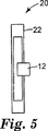
図3、5〜8に示されているように、本発明の組合せタグ20は、磁気応答素子を無線周波応答素子と組合せ、両者の利点を提供する。したがって、2つの素子を同時に対象の品目に適用することができ、それによってコストを削減する。組合せタグは、除去可能なライナによって覆われた感圧接着剤を備えていてもよく、ライナが除去されたときに、感圧接着剤によって組合せタグを物品の表面に接着させることができる。別の実施形態において、タグは、無線周波応答素子用のアンテナとして磁気応答素子を使用する。磁気応答素子は、アンテナとして使用されるときに、無線周波応答素子に電気的に結合され、無線周波応答素子に物理的に結合されても結合されなくてもよい。
【0023】
本発明によって製作された組合せタグは、2通りの方法で問合せを行うことができる。第1の方法では、RFID問合せ信号発生源は、集積回路からのコードの要求および受信を行うために、無線周波信号を使用する。この情報は、たとえば、タグが関連する物品の識別、物品が適切に処理されたかどうかなどを示す。第2の方法では、問合せ磁場は、マーカ組立品の磁気部分が能動であったかどうかを決定するために、タグに問合せる。マーカ組立品が能動であった場合には、問合せ信号発生源は、マーカ付きの物品が適切に処理されていないことの通知などの応答を発生する。磁気による問合せは無線周波による問合せより遮蔽に対する耐性があるため、組合せタグの磁気部分はセキュリティの強化となる。したがって、磁気タグおよびRFIDタグの両者の特徴が、一つの組合せタグに組合わされる。
【0024】
好ましい実施形態において、組合せタグは、無線周波応答素子の回路においてアンテナとしても機能する磁気応答素子を含む。両者の機能を実現するために、アンテナ材料は、(優れたセキュリティ素子として作用するために)低い保磁度およびきわめて高い透磁率を示す必要があり、(優れたアンテナとして機能を果たすために)高い導電率に加減する必要がある。さらに、アンテナの幾何学的構成は、両者の機能と互換性がなければならない。このような実施形態において、たとえば、パーマロイ、すなわちニッケルおよび鉄の合金からアンテナを製作することができる。
【0025】
一実施形態において、3M製の「Tattle−TapeTM」ブランドセキュリティストリップまたは他の等価な磁気素子は、2.45GHzまたは類似の高い周波数で作動するため、リニア型ダイポールアンテナとして使用することもできる。このようなストリップの長さ、幅および厚みは、使用されるRFIDチップの特定の作動周波数および他の特性に適合するように選択する。一般に、ストリップは、(商標名「HyMu80」で、Carpenter Specialty Alloys、Reading、PAを含むさまざまな製造業者から入手可能なパーマロイ)または2705Mの名称でAlliedSignal Company of Morristown,NYから入手可能なものなどのアモルファス合金から製作され、その長さは、6.35〜16.5cm(2.5〜6.5インチ)である。集積回路の端子は、セキュリティストリップの先端に物理的に接続される。インピーダンスおよび電力利得の電気測定は、磁気ストリップがチップなどに一般に使用される銅またはアルミニウムのダイポールアンテナと同一の基本的な電気特性を提供するということを確認し、したがって、両者の機能を十分に実現することが期待される。
【0026】
磁気応答素子が無線周波応答素子用のアンテナの少なくとも一部として使用される場合には、両者は互いに電気的に結合される。電気的な結合は、(図5に示されているように)複数の素子間の物理接続のために、または(図6に示されているように)物理接続がないために、非接触の電磁結合によって生じる可能性がある。非接触結合は、寄生結合、容量結合または誘導結合を含むことができ、このようなアンテナ構成要素として寄生アンテナ素子、反射器および指向アンテナ、八木−宇田アンテナまたは他の適切なアンテナ構成を使用する。
【0027】
図3に示された組合せタグは、磁気材料から製作されるコイルターンを含む。タグはたとえば、磁束コレクタがタグの磁気に関する機能を改善するためにコーナに設けられるような14cなどのアンテナ構造を有する13.56MHzのタグであってもよい。他の種類の磁束コレクタが設けられてもよい。
【0028】
図5に示される組合せタグ20は、磁気に応答する材料で製作されるアンテナ22と集積回路12との間の物理接続を含む。また、二状態タグを形成するために選択的に活性化および非活性化を行うことができる様にするために、1つ以上の保磁子または上述したような種類が磁気に応答する材料に適用されてもよい。しかし、図6に示されたアンテナ22aは、集積回路12またはダイポールアンテナ23に物理的に接続されていないが、組合せタグ20aを形成するために寄生ダイポール結合によってダイポールアンテナに電気的に結合される。ダイポールアンテナ23は、磁気に応答する材料または磁気に応答しない材料のいずれから構成されてもよい。
【0029】
図7および図8は、2つ以上のアンテナ22が、アンテナ23b,23cにそれぞれ電気的に結合されるように設けられた実施形態を示している。図7に示された組合せタグ20bにおいて、集積回路12は、アンテナ22bに寄生結合されるダイポールアンテナ23bを含む。アンテナ22bは磁気に応答する材料で製作され、アンテナ23bも磁気に応答する材料で製作されてもよい。図8に示された組合せタグ20cにおいて、図2に示された種類の無線周波応答素子はアンテナ22cに寄生によって電気結合される。アンテナ22cは磁気に反応する材料で製作され、アンテナ23cも磁気に応答する材料で製作されてもよい。このような実施形態の他の変形は簡単に設計される。
【0030】
組合せタグの全体厚さは、タグを物品の上または中に目立たないように配置することができるようにするために、できる限り小さくする必要がある。たとえば、タグは、書籍の頁の間に接着剤を用いて貼りつけられることもでき、書籍の端を見ることによって簡単に検出されることをを防止するのに十分なほどタグを薄くすることが望ましい。従来のICは厚さ約0.5mm(0.02インチ)であると考えられ、タグの全体厚さは0.635mm(0.025インチ)未満であることが好ましい。
【0031】
本発明の組合せタグは、物品に個別のタグを自動的に順次貼付することができるようにするために、ロール形状で提供されることもある。この汎用システムは、たとえば、PCT出願第WO97/36270(DeValeら)に記載されている。1面以上の面が(感圧接着剤などの)接着剤によって覆われた個別の組合せタグをロールから取外し、書籍の2つの頁の間の結合部付近に貼りつけることができる。頁スプレッダが、組合せタグの挿入を迅速に行うことができるように設けられてもよく、さまざまな構成要素の位置を検出するために、システムにセンサなどの他のオプションが設けられてもよい。
【0032】
本発明の組合せタグは、専用ではないが、図書資料の処理において特定の用途を有すると考えられる。この種のRFIDタグを有する図書資料は、恐らく人手を介することなく簡単に貸出しおよび返却を行うことができると思われる。したがって、図書館利用者が適切な検出領域を通過すると、資料は(利用者が図書カードに関係づけたRFIDタグを所持している)特定の図書館利用者に自動的に貸出され、その図書館利用者が資料を図書館に再び持ち込むと返却されることになる。本発明のタグはまた、図書館の管理者が瞬時かつ連続的に資料の追跡を行うことができることによって、在庫管理および分析の助けにもなることができる。本発明の以上の特徴および他の特徴はもちろん、商店、倉庫および同類物における構成要素の処理など他の用途に広めることもできる。
【0033】
別の実施形態において、本発明の組合せタグは、(タグの磁気特性が活性化または非活性化のいずれであるかを示す)磁気応答および(適切なソフトウェアの使用によって、データベースまたはRFIDチップ自体のメモリが、品目が適切に処理されたことを示しているかどうかを表す)無線周波応答の両方を用いて、二状態マーカ情報を得ることができる。
【0034】
本発明は、さらに以下の実施形態と共に説明される。
【0035】
実施形態
実施形態1
組合せタグが本発明によって製作された。「HyMu80」の名称でCarpenter Technology Corporation of Reading,Pennsylvaniaから入手可能な合金から製作されたパーマロイストリップが、Single Chip Systems(SCS) of San Diego,Californiaによって製作された試験部品に取り付けられた。ストリップは、幅約1.6mm(0.625インチ)×厚さ0.0254mm(0.001インチ)×長さ10.16cm(4インチ)と測定された。試験部品は、LEDダイオードに接続された標準型SCS 2.45GHzアンテナからなる。その部品は、代表的なSCS RFIDタグに電力を供給するのに十分なほど強い2.45GHzの場にさらされると、LEDが点灯し、部品の電力受信部の適切な動作をすぐに目で確認することができるように設計された。標準型SCSアンテナをプロトタイプ型パーマロイアンテナに交換するとすぐに、LEDはほぼ同様の場の強さで明るくなり、プロトタイプ型の作動の成功が確認された。
【0036】
実施形態2
図3は、13.56MHz RFID設計で有用と考えられているアンテナの別の実施形態を示している。この周波数では、コイル型アンテナの幾何学的構成が好ましい。コイルを形成する螺旋型ターンは、エッチング(物理的または化学的)、打抜きまたはマスクによる蒸着のいずれかによって、パーマロイなどの磁気合金から製作される。コイルのまっすぐな「アーム」部分はまた、この設計において磁気応答素子としても作用する。しかし、この幾何学的構成においてこれらの金属素子の長さを削減することは、装置の磁気セキュリティ部分の効果を制限する。図3に示された実施形態において、コーナに設けられる磁束収集素子が、この制限を克服するためにアンテナコイルに追加された。図3に示された構造は、アンテナの作動周波数を規定された問合せ周波数に同調させるために、前述したように、コンデンサを含むことが好ましい。
【0037】
この実施例において記載されたアンテナの特性が、無線周波集積回路用として周知のアンテナの特性と比較された。これらの特性は類似しているため、この実施形態のアンテナは、このような用途において適切に機能していると考えられる。
【0038】
本発明は、いくつかの実施形態について述べてきた。当業者は、記載された実施形態の修正も本発明の範囲内であることを理解されたい。
本発明は、添付の図面と共にさらに詳細に説明され、同一の参照符号は、複数の図にわたって同一の構造物を示す。
【図面の簡単な説明】
【図1A】 無線周波識別タグの概略図である。
【図1B】 無線周波識別タグの概略図である。
【図2】 無線周波識別タグの第2の実施形態の概略図である。
【図3】 本発明による組合せタグの概略上面図である。
【図4】 RFIDタグと互いに影響を及ぼし合うRFID問合せシステムのブロックである。
【図5】 本発明による組合せタグの図である。
【図6】 本発明による組合せタグの図である。
【図7】 本発明による組合せタグの図である。
【図8】 本発明による組合せタグの図である。[0001]
Technical field
The present invention relates to an identification tag of the type used with detectors to identify and monitor objects such as library media and consumer goods.
[0002]
Background art
Electronic article surveillance (“EAS”) systems detect the presence of small electronic devices that are placed on or in an article or carried by a person of interest and prevent theft or unauthorized removal of the article Often used in retail or library environments. In the past, such devices, commonly known as tags or markers, contained only information regarding the presence of items. Such information can be obtained by electronically querying the tag either intermittently or continuously. Based on the way in which this query is performed, namely magnetic, magnetomechanical, radio frequency and microwave, at least four different types of EAS systems have evolved over the years. Of these four types, magnetic systems have provided the highest level of security in most applications. Magnetic tags can be easily hidden in or on objects, are difficult to disable (because they are less susceptible to shielding, bending and pressure) and are easy to deactivate or activate, Provides certain information about security and tagged items.
[0003]
Many users of the EAS system want to know more than whether there is a tagged object. For example, you want to know which tagged objects are present. Detailed information about object features such as date of manufacture, inventory information and owners has been communicated to the automated process control system by optical bar codes. Optical bar code systems are inexpensive and efficient, but have certain limitations. Since barcodes must be visible, there are restrictions on where they can be placed, and barcodes can be easily obscured intentionally or intentionally. The range in which the detector can detect the barcode is also relatively small. The barcode may also have to be placed in the proper location for detection. In addition, since the bar code is often bare so that it can be detected, the bar code is susceptible to damage that can cause it to be undetectable. Finally, multiple items must be processed simultaneously. This constraint of the bar code system is undesirable or inefficient for some applications such as library media marking.
[0004]
More recently, electronic identification (also known as radio frequency identification or RFID) technology has been developed to address the limitations of optical barcodes. Although RFID systems have been successful in identifying or tracking objects, most RFID systems operate in the frequency domain (on the order of 1 MHz or more) where tags are easily invalidated. Insufficient to provide security for things. For example, the tags associated with radio frequency tags are lacking because the tags can also be “shielded” by covering the tags with hands or aluminum foil or by placing the tags in a book. The radio frequency tag supplied with battery power has a higher output and is difficult to shut off, but this may also be shut off. Therefore, there is a risk that an object with an RFID tag is escaped from detection by chance or deliberately. Such a situation greatly reduces the effectiveness of the security device. RFID markers are also related to “smart cards”. Both contact and contactless smart cards have been found in the commercial field. Smart cards tend to relate to a particular person rather than tagged objects. Problems with security and tracking of a smart card (or the person holding it) are similar to those described above with respect to RFID markers.
[0005]
The security issues associated with RFID markers are similar to those familiar to those skilled in the art of radio frequency and microwave based EAS tags. Substantial efforts have been made in an attempt to improve the deficiencies of radio frequency and microwave based EAS tags. However, the performance as a security tag has not been improved substantially. U.S. Pat. No. 5,517,195 (Narlow et al.) Entitled "Dual Frequency EAS Tag with Deactivation Coil" using a deactivation coil is disclosed in US Pat. No. 5,517,195. A dual-frequency microwave EAS tag is described. The deactivation circuit responds to a low energy alternating magnetic field by inducing a voltage across the diode of the antenna circuit to defeat the diode and antenna capabilities, thereby deactivating the tag. Although useful in some applications, the capacitor-based tag published by Narrow et al. Can leak charge over time and can cause unintentional activation of the tag.
[0006]
A radio frequency EAS tag of the type disclosed in US Pat. No. 4,745,401 (Montean et al.) Includes a magnetic element. If the magnetic element is properly magnetized by the accessory device, it changes the tuning of the tag, thereby blocking the tag's radio frequency response. While such tags have certain utility, they have not yet addressed issues related to security and enhanced identification.
[0007]
Radio frequency identification techniques include Motorola / Indala (see US Pat. No. 5,378,880 and US Pat. No. 5,565,846), Texas Instruments (US Pat. No. 5,347,280 and US Pat. 541,604), Mikron / Philips Semiconductor, Single Chip Systems (US Pat. No. 4,442,507, US Pat. No. 4,796,074, US Pat. No. 5,095,362, US Pat. , 296,722 and US Pat. No. 5,407,851), CSIR (European Patent Publication No. 0 494 114 A2, European Patent Publication No. 0 585 132 A1, European Patent Publication No. 0 598 624 A1 and See European Patent Publication No. 0 615 285 A2. ), IBM (see U.S. Pat. No. 5,528,222, U.S. Pat. No. 5,550,547, U.S. Pat. No. 5,521,601 and U.S. Pat. No. 5,682,143) and Sensory Electronics (U.S. Pat. (See Japanese Patent No. 5,625,341). All such tags are an attempt to provide remote identification without the need for a battery. The tag operates at a frequency between 125 KHz and 2.45 GHz. Even lower frequency tags (less than 125 KHz) are reasonably resistant to shielding but have only limited radio frequency capabilities due to bandwidth constraints. In particular, such marker-based systems generally only work reliably if a single tag is in the query area at the same time. Such systems also tend to be relatively large and expensive to manufacture. To develop a system that can reliably process multiple tags in the query area in a short period of time with higher bandwidth (usually 13.56 MHz, 915 MHz and 2.45 GHz) and the additional bandwidth available I was able to. This is highly desirable for various product applications. In addition, some tag designs are likely to be more attractive to consumers due to their relatively low manufacturing costs. However, such a higher frequency device is similar to the tag described above in that the degree of influence of shielding changes. Therefore, it cannot provide the high level of security required in certain applications such as libraries.
[0008]
Thus, it would be desirable to provide inexpensive and secure tags that could be used, for example, on airline baggage, next-day delivery parcels and library books to provide object identification, tracking and security.
[0009]
Disclosure of the invention
The present invention minimizes or eliminates the disadvantages associated with conventional tags of the type described above by providing a tag that includes a combination of magnetic and radio frequency response elements. By providing both elements in a single combination tag, the respective features are realized and the respective drawbacks are overcome. In one embodiment, the magnetic response element is an antenna for a radio frequency response element by being physically connected to the radio frequency response element or by being electrically coupled but not physically connected. Acts as
[0010]
Details of the invention
The tag of the present invention incorporates both object identification and effective security in a single device. An element responsive to the magnetic interrogation signal and an element responsive to the radio frequency interrogation signal. In one embodiment, the magnetic response element also provides an antenna for the radio frequency response element. The term “respond” means in the context of the present invention to provide information that can be understood when the device is exposed to an appropriate query point. The individual elements are first described below, then proceeding to the details of the combination tag of the present invention.
[0011]
I. Magnetic response element
The magnetic response element of the present invention is a trademark “TATTLETAPE”. TM "In the name of the brand strip Minnesota Mining and Manufacturing Company of St. It is preferably made from a ferromagnetic material with low coercivity and high permeability, such as the material used for the strip sold by Paul, Minnesota (3M). Such strips or marker assemblies are described in several patents assigned to 3M, including US Pat. No. 5,331,313 (Koning) and US Pat. No. 3,747,086 (Peterson). Are listed. Exemplary ferromagnetic materials with low coercivity and high permeability include permalloy (nickel / iron alloys) and high performance such as those available from AlliedSignal Company of Morristown, NY under the trademarks Metglas 2705M and Metglas 2714A. An amorphous metal is mentioned.
[0012]
The magnetic response element may be in a single state or in two states depending on the nature of the article with which the element is associated. For example, certain reference books in a library are not subject to removal from the library, so a single state (cannot be deactivated) marker is such a book does not go beyond the query area Will always indicate whether or not. Other articles, such as regular library materials or merchandise, require a two-state marker assembly that can be properly deactivated to prevent detection by an interrogation signal source when the article is properly processed There is also something to do. The two-state function is mainly the addition of a higher coercivity magnetic material portion in the vicinity of the low coercivity magnetic material in the patent granted to Peterson referred to above, as described below. Obtained by.
[0013]
Some magnetic responsive elements are capable of rapidly switching the direction of magnetism when passing through a low frequency alternating magnetic field (e.g., 50 Hz to 100 KHz) and can be detected by a receiver coil of the detector. Response can be generated. The switching function of the marker assembly is controlled by the magnetization state of an element with high coercivity or a “coercivity”. When such a coercive element is magnetized, the ability of the marker to switch magnetic orientation within the alternating magnetic field of the interrogation region is altered and the marker is not normally detected. When the coercive element is demagnetized, the marker can perform the switching function again, and the interrogation signal source can detect the presence of the marker. As is known in the art, the coercive elements may be provided in different ways.
[0014]
The marker assembly may also have an adhesive on one or both sides to adhere the marker to a book or other article. In order to prevent the marker from adhering to an unintended surface before being applied to a predetermined surface, the adhesive surface can be covered with a removable liner. For these and other features of the marker assembly, see U.S. Pat. No. 3,790,945 (Fearon), U.S. Pat. No. 5,083,112 (Piotroski) and U.S. Pat. No. 5,331,313. Koning).
[0015]
This type of low frequency magnetic element is difficult to shield from detection and can be used effectively on a variety of items where security is important. In addition, low frequency magnetic elements are much more convenient than markers using other EAS technologies, and this property is highly desirable because they can be deactivated and reactivated completely and repeatedly. Appropriate for certain uses (such as libraries).
[0016]
II. Radio frequency response element
The RFID tag may be either passive or active. Active tags incorporate additional energy sources, such as batteries, into the tag structure. Such an energy source forms an active RFID tag and can transmit a strong response signal even in a region where the radio frequency field to be queried is weak, so that the active RFID tag can be detected in a wider region. However, due to the relatively short life of the battery, the useful life of the tag is limited. In addition, the battery increases the size and cost of the tag. A passive tag derives the energy required to power the tag from the interrogating radio frequency field and uses that energy to transmit a response code by modulating the impedance the antenna provides to the interrogation field Thus, the signal reflected to the reading antenna is modulated. Therefore, this area is further limited. Since passive tags are preferred for many applications, the remainder of the discussion is limited to this type of tag. However, those skilled in the art will appreciate that these two types of tags share many features, both of which can be used in connection with the present invention.
[0017]
As shown in FIG. 1, the passive radio
[0018]
The antenna geometry and characteristics depend on the desired operating frequency of the RFID portion of the tag. For example, 2.45 GHz (or similar) RFID tags typically include a linear dipole antenna as shown in FIG. 1A and a folded dipole antenna shown attached to the radio
[0019]
[Expression 1]
C = Capacitance (unit: farad)
L = Inductance (Unit: Henry)
And closely match the desired operating frequency of the RFID system. The capacitor may also be a distributed capacitor, as described in US Pat. No. 4,598,276 (Tait et al.) And US Pat. No. 4,578,654 (Tait et al.) Assigned to 3M. . Distributed capacitance is desirable for tag size, specifically thickness reduction and minimization of manual assembly.
[0020]
In the operational state, as shown in FIG. 4, the radio
[0021]
The
[0022]
III. Combination tag
As shown in FIGS. 3 and 5-8, the
[0023]
Combination tags made in accordance with the present invention can be queried in two ways. In the first method, the RFID interrogation signal source uses radio frequency signals to request and receive codes from the integrated circuit. This information indicates, for example, the identification of the item with which the tag is associated, whether the item has been properly processed, etc. In the second method, the interrogation field interrogates the tag to determine if the magnetic portion of the marker assembly was active. If the marker assembly is active, the interrogation signal source generates a response, such as a notification that the item with the marker has not been properly processed. Since the inquiry by magnetism is more resistant to shielding than the inquiry by radio frequency, the magnetic part of the combination tag is a security enhancement. Therefore, the features of both the magnetic tag and the RFID tag are combined into one combination tag.
[0024]
In a preferred embodiment, the combination tag includes a magnetic response element that also functions as an antenna in the circuit of the radio frequency response element. In order to realize both functions, the antenna material must exhibit low coercivity and extremely high permeability (to function as an excellent antenna) and to function as an excellent antenna. It is necessary to adjust to high conductivity. Furthermore, the antenna geometry must be compatible with both functions. In such an embodiment, for example, the antenna can be fabricated from permalloy, ie, an alloy of nickel and iron.
[0025]
In one embodiment, 3M's “Tattle-Tape” TM "Brand security strips or other equivalent magnetic elements can also be used as linear dipole antennas because they operate at 2.45 GHz or similar high frequencies. The length, width and thickness of such strips are selected to suit the specific operating frequency and other characteristics of the RFID chip used. In general, strips are (permalloys available from various manufacturers, including the trade name “HyMu80”, Carpenter Specialty Alloys, Reading, PA) or those available from AlliedSignal of Morristown, NY under the name 2705M. Manufactured from an amorphous alloy, its length is between 2.5 and 6.5 inches (6.35 to 16.5 cm). The terminals of the integrated circuit are physically connected to the tip of the security strip. Electrical measurements of impedance and power gain confirm that the magnetic strip provides the same basic electrical characteristics as a copper or aluminum dipole antenna commonly used for chips etc., and therefore fully function both It is expected to be realized.
[0026]
When the magnetic response element is used as at least part of the antenna for the radio frequency response element, they are electrically coupled to each other. Electrical coupling is non-contact because of physical connections between multiple elements (as shown in FIG. 5) or because there is no physical connection (as shown in FIG. 6). It can be caused by electromagnetic coupling. Non-contact coupling can include parasitic coupling, capacitive coupling or inductive coupling, using parasitic antenna elements, reflectors and directional antennas, Yagi-Uda antennas or other suitable antenna configurations as such antenna components. .
[0027]
The combination tag shown in FIG. 3 includes coil turns made from magnetic material. The tag may be, for example, a 13.56 MHz tag having an antenna structure such as 14c such that a magnetic flux collector is provided at the corner to improve the tag's magnetic function. Other types of magnetic flux collectors may be provided.
[0028]
The
[0029]
7 and 8 show an embodiment in which two or
[0030]
The total thickness of the combination tag needs to be as small as possible so that the tag can be placed inconspicuously on or in the article. For example, a tag can be affixed between pages of a book using an adhesive, making the tag thin enough to prevent it from being easily detected by looking at the edge of the book Is desirable. Conventional ICs are believed to be about 0.5 mm (0.02 inch) thick, and the overall thickness of the tag is preferably less than 0.625 mm (0.025 inch).
[0031]
The combination tag of the present invention may be provided in a roll shape so that individual tags can be automatically and sequentially affixed to the article. This general purpose system is described, for example, in PCT Application No. WO 97/36270 (DeVale et al.). Individual combination tags with one or more sides covered by an adhesive (such as a pressure sensitive adhesive) can be removed from the roll and affixed near the junction between the two pages of the book. A page spreader may be provided to allow quick insertion of combination tags, and other options such as sensors may be provided in the system to detect the position of various components.
[0032]
The combination tag of the present invention is not dedicated, but is considered to have a specific use in the processing of library materials. Book materials with this type of RFID tag can probably be lent and returned easily without human intervention. Thus, when a library user passes the appropriate detection area, the material is automatically rented to a particular library user (who owns the RFID tag associated with the book card) and the library user Will be returned when the material is brought back to the library. The tags of the present invention can also assist in inventory management and analysis by allowing library managers to track material instantaneously and continuously. These and other features of the present invention can of course be extended to other applications such as processing components in stores, warehouses and the like.
[0033]
In another embodiment, the combination tag of the present invention comprises a magnetic response (indicating whether the tag's magnetic properties are activated or deactivated) and the database or RFID chip itself (using appropriate software). Bi-state marker information can be obtained using both the radio frequency response (which indicates whether the memory indicates that the item has been properly processed).
[0034]
The invention is further described in conjunction with the following embodiments.
[0035]
Embodiment
Embodiment 1
A combination tag was made according to the present invention. A permalloy strip made from an alloy available from Carpenter Technology Corporation of Reading, Pennsylvania under the name “HyMu80” was manufactured by the Single Chip Systems (SCS) of San Diego, Calif. The strips were measured to be approximately 1.6 mm (0.625 inches) wide by 0.0254 mm (0.001 inches) long by 10.16 cm (4 inches) long. The test part consists of a standard SCS 2.45 GHz antenna connected to an LED diode. When the part is exposed to a 2.45 GHz field strong enough to power a typical SCS RFID tag, the LED will illuminate and the proper operation of the part's power receiver will be immediately visible. Designed to be able to confirm. As soon as the standard SCS antenna was replaced with a prototype permalloy antenna, the LED became bright with almost the same field strength, confirming the successful operation of the prototype.
[0036]
Embodiment 2
FIG. 3 shows another embodiment of an antenna that is considered useful in a 13.56 MHz RFID design. At this frequency, a coiled antenna geometry is preferred. The helical turns forming the coil are made from a magnetic alloy such as permalloy, either by etching (physical or chemical), stamping or mask deposition. The straight “arm” portion of the coil also acts as a magnetic response element in this design. However, reducing the length of these metal elements in this geometric configuration limits the effectiveness of the magnetic security portion of the device. In the embodiment shown in FIG. 3, a flux collecting element provided at the corner was added to the antenna coil to overcome this limitation. The structure shown in FIG. 3 preferably includes a capacitor, as described above, to tune the antenna's operating frequency to a defined interrogation frequency.
[0037]
The characteristics of the antenna described in this example were compared with those of antennas well known for radio frequency integrated circuits. Since these characteristics are similar, the antenna of this embodiment is considered to function properly in such applications.
[0038]
The present invention has been described in several embodiments. Those skilled in the art will appreciate that modifications to the described embodiments are within the scope of the invention.
The present invention will be described in more detail in conjunction with the accompanying drawings, wherein like reference numerals designate like structures throughout the several views.
[Brief description of the drawings]
FIG. 1A is a schematic diagram of a radio frequency identification tag.
FIG. 1B is a schematic diagram of a radio frequency identification tag.
FIG. 2 is a schematic diagram of a second embodiment of a radio frequency identification tag.
FIG. 3 is a schematic top view of a combination tag according to the present invention.
FIG. 4 is a block of an RFID interrogation system that interacts with an RFID tag.
FIG. 5 is a diagram of a combination tag according to the present invention.
FIG. 6 is a diagram of a combination tag according to the present invention.
FIG. 7 is a diagram of a combination tag according to the present invention.
FIG. 8 is a diagram of a combination tag according to the present invention.
Claims (9)
(b)格納情報の更新が可能な集積回路を含む無線周波応答素子を具備し、
前記無線周波応答素子は、情報記憶、及び問い合わせシステムが前記無線周波応答素子から情報を得るのを可能にする送信機能を有し、
前記無線周波応答素子は、前記磁気応答素子に電気的に結合され、前記磁気応答素子をアンテナの少なくとも一部として使用する組合せタグ。(A) a magnetic response element capable of detecting a security element; and (b) a radio frequency response element including an integrated circuit capable of updating stored information .
The radio frequency response element has an information storage and transmission function that enables an inquiry system to obtain information from the radio frequency response element;
The radio frequency response element is electrically coupled to the magnetic response element and uses the magnetic response element as at least part of an antenna.
Applications Claiming Priority (3)
| Application Number | Priority Date | Filing Date | Title |
|---|---|---|---|
| US09/093,120 US6154137A (en) | 1998-06-08 | 1998-06-08 | Identification tag with enhanced security |
| US09/093,120 | 1998-06-08 | ||
| PCT/US1998/023412 WO1999065006A1 (en) | 1998-06-08 | 1998-11-03 | Identification tag with enhanced security |
Publications (3)
| Publication Number | Publication Date |
|---|---|
| JP2002517764A JP2002517764A (en) | 2002-06-18 |
| JP2002517764A5 JP2002517764A5 (en) | 2006-01-05 |
| JP4263359B2 true JP4263359B2 (en) | 2009-05-13 |
Family
ID=22237292
Family Applications (1)
| Application Number | Title | Priority Date | Filing Date |
|---|---|---|---|
| JP2000553935A Expired - Fee Related JP4263359B2 (en) | 1998-06-08 | 1998-11-03 | Identification tag with enhanced security |
Country Status (12)
| Country | Link |
|---|---|
| US (2) | US6154137A (en) |
| EP (1) | EP1086444B1 (en) |
| JP (1) | JP4263359B2 (en) |
| KR (1) | KR100609301B1 (en) |
| CN (1) | CN1150497C (en) |
| AR (1) | AR018404A1 (en) |
| AU (1) | AU751816B2 (en) |
| BR (1) | BR9815893A (en) |
| CA (1) | CA2333566A1 (en) |
| DE (1) | DE69811740T2 (en) |
| ES (1) | ES2190613T3 (en) |
| WO (1) | WO1999065006A1 (en) |
Families Citing this family (158)
| Publication number | Priority date | Publication date | Assignee | Title |
|---|---|---|---|---|
| US6154137A (en) | 1998-06-08 | 2000-11-28 | 3M Innovative Properties Company | Identification tag with enhanced security |
| US6704690B2 (en) * | 1998-06-08 | 2004-03-09 | St. Logitrack Pte Ltd. | Monitoring system |
| JP2002522849A (en) | 1998-08-14 | 2002-07-23 | スリーエム イノベイティブ プロパティズ カンパニー | Radio Frequency Identification System Applications |
| WO2000010112A1 (en) | 1998-08-14 | 2000-02-24 | 3M Innovative Properties Company | Application for a radio frequency identification system |
| US6424262B2 (en) | 1998-08-14 | 2002-07-23 | 3M Innovative Properties Company | Applications for radio frequency identification systems |
| CN1158636C (en) | 1998-08-14 | 2004-07-21 | 3M创新有限公司 | Applications for radio frequency identification systems |
| US8228193B1 (en) * | 1998-09-14 | 2012-07-24 | Tuemer Tuemay O | Tag having a semiconductor chip and method of attachment to article |
| WO2000036572A1 (en) * | 1998-09-30 | 2000-06-22 | Intermec Ip Corp. | Combination radio frequency identification transponder (rfid tag) and magnetic electronic article suveillance (eas) tag |
| EP1136945B1 (en) * | 1998-11-30 | 2007-01-03 | Hitachi, Ltd. | Method for mounting electronic circuit chip |
| US6615074B2 (en) * | 1998-12-22 | 2003-09-02 | University Of Pittsburgh Of The Commonwealth System Of Higher Education | Apparatus for energizing a remote station and related method |
| US6542720B1 (en) * | 1999-03-01 | 2003-04-01 | Micron Technology, Inc. | Microelectronic devices, methods of operating microelectronic devices, and methods of providing microelectronic devices |
| US6333692B1 (en) * | 1999-07-06 | 2001-12-25 | Ats Money Systems Inc. | Security tag deactivation system |
| US20010037248A1 (en) * | 2000-05-01 | 2001-11-01 | Elliot Klein | Product warranty registration system and method |
| US6965866B2 (en) * | 2000-05-01 | 2005-11-15 | Elliot Klein | Product warranty registration system and method |
| CN1340185A (en) * | 1999-11-05 | 2002-03-13 | 索尼株式会社 | Data decoding device and method, charging information processing device and method, data reproducing device and method, electronic money, electronic right of use, and terminal |
| DE19957557A1 (en) * | 1999-11-30 | 2001-06-07 | Siemens Ag | Identification system, esp. for vehicle |
| MXPA02007518A (en) * | 2000-02-04 | 2003-01-28 | 3M Innovative Properties Co | Method of authenticating a tag. |
| US6451154B1 (en) | 2000-02-18 | 2002-09-17 | Moore North America, Inc. | RFID manufacturing concepts |
| US7878905B2 (en) * | 2000-02-22 | 2011-02-01 | Creative Kingdoms, Llc | Multi-layered interactive play experience |
| US7445550B2 (en) | 2000-02-22 | 2008-11-04 | Creative Kingdoms, Llc | Magical wand and interactive play experience |
| US7113095B2 (en) | 2000-05-22 | 2006-09-26 | Avery Dennison Corp. | Trackable files and systems for using the same |
| EP1172760B1 (en) * | 2000-06-23 | 2004-12-01 | Toyo Aluminium Kabushiki Kaisha | Antenna coil for IC card and manufacturing method thereof |
| FR2812482B1 (en) * | 2000-07-28 | 2003-01-24 | Inside Technologies | PORTABLE ELECTRONIC DEVICE COMPRISING SEVERAL INTEGRATED NON-CONTACT CIRCUITS |
| US6373387B1 (en) * | 2000-08-08 | 2002-04-16 | Honeywell International Inc. | Integrated hybrid electronic article surveillance marker |
| JP3908448B2 (en) * | 2000-08-17 | 2007-04-25 | 日本電気株式会社 | Mobile telephone device and its built-in antenna |
| FR2814574B1 (en) * | 2000-09-22 | 2003-11-28 | Gemplus Card Int | NON-CONTACT ELECTRONIC LABEL FOR CONDUCTIVE SURFACE PRODUCT |
| US6975834B1 (en) * | 2000-10-03 | 2005-12-13 | Mineral Lassen Llc | Multi-band wireless communication device and method |
| US6600418B2 (en) | 2000-12-12 | 2003-07-29 | 3M Innovative Properties Company | Object tracking and management system and method using radio-frequency identification tags |
| US6951596B2 (en) | 2002-01-18 | 2005-10-04 | Avery Dennison Corporation | RFID label technique |
| US6816075B2 (en) | 2001-02-21 | 2004-11-09 | 3M Innovative Properties Company | Evidence and property tracking for law enforcement |
| US20020180588A1 (en) * | 2001-06-05 | 2002-12-05 | Erickson David P. | Radio frequency identification in document management |
| US6968686B2 (en) * | 2001-07-11 | 2005-11-29 | Hideaki Okada | Operation mechanism of a variable displacement hydraulic pump |
| US20030030542A1 (en) * | 2001-08-10 | 2003-02-13 | Von Hoffmann Gerard | PDA security system |
| JP4843885B2 (en) * | 2001-08-31 | 2011-12-21 | 凸版印刷株式会社 | Fraud prevention label with IC memory chip |
| JP2003078435A (en) * | 2001-09-03 | 2003-03-14 | Dainippon Printing Co Ltd | Radio communication equipment |
| US6894615B2 (en) * | 2001-10-09 | 2005-05-17 | 3M Innovative Properties Company | Article with retroreflective and radio frequency-responsive features |
| US20030069815A1 (en) * | 2001-10-10 | 2003-04-10 | 3M Innovative Properties Company | RFID time tracking |
| EP1454180B1 (en) * | 2001-11-09 | 2007-07-18 | International Barcode Corporation | System and method for embedding characters in a bar of a bar code |
| US7207491B2 (en) * | 2001-11-09 | 2007-04-24 | International Barcode Corporation | System and method for generating a combined bar code image |
| US6669089B2 (en) | 2001-11-12 | 2003-12-30 | 3M Innovative Properties Co | Radio frequency identification systems for asset tracking |
| US7322514B2 (en) * | 2001-11-30 | 2008-01-29 | International Barcode Corporation | Method for identifying and authenticating goods using codes, barcodes and radio frequency identification |
| JP2005512371A (en) * | 2001-11-30 | 2005-04-28 | インターナショナル バーコード コーポレイション | System and method for verifying digital images and corresponding data |
| US6758405B2 (en) | 2001-12-19 | 2004-07-06 | 3M Innovative Properties Company | Article with retroreflective and radio frequency-responsive features |
| US6825766B2 (en) | 2001-12-21 | 2004-11-30 | Genei Industries, Inc. | Industrial data capture system including a choke point portal and tracking software for radio frequency identification of cargo |
| US8339265B2 (en) | 2002-01-09 | 2012-12-25 | Sensormatic Electronics, Llc. | Method of assigning and deducing the location of articles detected by multiple RFID antennae |
| CA2473136C (en) * | 2002-01-09 | 2013-04-16 | Meadwestvaco Corporation | Intelligent station using multiple rf antennae and inventory control system and method incorporating same |
| US6854647B2 (en) * | 2002-02-01 | 2005-02-15 | Ncr Corporation | Checkout device including integrated barcode reader, scale, and EAS system |
| DE60336771D1 (en) * | 2002-02-01 | 2011-05-26 | Datalogic Scanning Inc | System and method for data reading and EAS tag capture and disassembly at checkout |
| US6783072B2 (en) | 2002-02-01 | 2004-08-31 | Psc Scanning, Inc. | Combined data reader and electronic article surveillance (EAS) system |
| US7119693B1 (en) * | 2002-03-13 | 2006-10-10 | Celis Semiconductor Corp. | Integrated circuit with enhanced coupling |
| US7527198B2 (en) | 2002-03-18 | 2009-05-05 | Datalogic Scanning, Inc. | Operation monitoring and enhanced host communications in systems employing electronic article surveillance and RFID tags |
| US7383864B2 (en) | 2002-04-03 | 2008-06-10 | 3M Innovative Properties Company | Radio-frequency identification tag and tape applicator, radio-frequency identification tag applicator, and methods of applying radio-frequency identification tags |
| US20070066396A1 (en) | 2002-04-05 | 2007-03-22 | Denise Chapman Weston | Retail methods for providing an interactive product to a consumer |
| US6967566B2 (en) | 2002-04-05 | 2005-11-22 | Creative Kingdoms, Llc | Live-action interactive adventure game |
| US20030189094A1 (en) * | 2002-04-09 | 2003-10-09 | Trabitz Eugene L. | Baggage tracking system |
| PT102793A (en) * | 2002-06-18 | 2003-12-31 | Gantle Trading & Services Ld | DEVICE FOR INDIVIDUALIZED IDENTIFICATION OF REMOTE ITEMS |
| GB2390508A (en) * | 2002-07-03 | 2004-01-07 | Marconi Information Systems Lt | Variable frequency tag and interogation system |
| US20040044956A1 (en) * | 2002-08-27 | 2004-03-04 | Silicon Valley Micro C Corporation | Intelligent document |
| JP2004094839A (en) * | 2002-09-04 | 2004-03-25 | Hitachi Ltd | Rfid tag |
| US9446319B2 (en) | 2003-03-25 | 2016-09-20 | Mq Gaming, Llc | Interactive gaming toy |
| US7345583B2 (en) * | 2003-04-08 | 2008-03-18 | Kma Global Solutions Inc. | Dual security label |
| US6894527B1 (en) * | 2003-05-12 | 2005-05-17 | Xilinx, Inc. | Evolved circuits for bitstream protection |
| US7081818B2 (en) * | 2003-05-19 | 2006-07-25 | Checkpoint Systems, Inc. | Article identification and tracking using electronic shadows created by RFID tags |
| US7183917B2 (en) * | 2003-05-19 | 2007-02-27 | Checkpoint Systems, Inc. | EAS/RFID identification hard tags |
| EP2264650B1 (en) * | 2003-07-07 | 2014-02-26 | Avery Dennison Corporation | RFID device with changeable characteristics |
| US7398054B2 (en) * | 2003-08-29 | 2008-07-08 | Zih Corp. | Spatially selective UHF near field microstrip coupler device and RFID systems using device |
| US7388488B2 (en) * | 2003-10-30 | 2008-06-17 | Peter Lupoli | Method and system for storing, retrieving, and managing data for tags |
| US7956742B2 (en) | 2003-10-30 | 2011-06-07 | Motedata Inc. | Method and system for storing, retrieving, and managing data for tags |
| US20050091821A1 (en) * | 2003-11-03 | 2005-05-05 | Best Scott D. | Method of manufacturing an article having a radio frequency identification (RFID) device |
| US7767457B2 (en) * | 2004-01-20 | 2010-08-03 | Inki Mun | Method of use of taggants |
| KR20060132735A (en) | 2004-02-20 | 2006-12-21 | 체크포인트 시스템즈 인코포레이티드 | System and method for authenticated detachment of product tags |
| EP1760900B1 (en) * | 2004-06-10 | 2011-04-06 | Panasonic Corporation | Rfid tag and rfid tag communication distance modification method |
| US8596532B2 (en) | 2004-06-10 | 2013-12-03 | Zih Corp. | Apparatus and method for communicating with an RFID transponder |
| US7549591B2 (en) * | 2004-06-28 | 2009-06-23 | International Barcode Corporation | Combined multi-frequency electromagnetic and optical communication system |
| US7284704B2 (en) * | 2004-06-28 | 2007-10-23 | International Barcode Corporation | Combined electromagnetic and optical communication system |
| US7307527B2 (en) | 2004-07-01 | 2007-12-11 | Avery Dennison Corporation | RFID device preparation system and method |
| US20060012482A1 (en) * | 2004-07-16 | 2006-01-19 | Peter Zalud | Radio frequency identification tag having an inductively coupled antenna |
| US7500307B2 (en) | 2004-09-22 | 2009-03-10 | Avery Dennison Corporation | High-speed RFID circuit placement method |
| JP4597629B2 (en) * | 2004-10-08 | 2010-12-15 | 富士通株式会社 | Information holding device access device and electronic device incorporating the access device |
| KR101038493B1 (en) * | 2004-11-12 | 2011-06-01 | 삼성테크윈 주식회사 | UHF RFID tag and Manufacturing method thereof |
| US7243476B2 (en) * | 2004-12-03 | 2007-07-17 | Checkpoint Systems, Inc. | Method and system for tracking items in a shipping facility |
| TW200628062A (en) * | 2004-12-03 | 2006-08-01 | Nitta Corp | Electromagnetic interference suppressor, antenna device, and electron information transfer device |
| US7295120B2 (en) * | 2004-12-10 | 2007-11-13 | 3M Innovative Properties Company | Device for verifying a location of a radio-frequency identification (RFID) tag on an item |
| US7316352B1 (en) | 2004-12-23 | 2008-01-08 | Storage Technology Corporation | System and method for locked code on a radio frequency identification tag |
| JP4667397B2 (en) * | 2005-01-17 | 2011-04-13 | 富士通株式会社 | Communication apparatus and communication method |
| US7619527B2 (en) | 2005-02-08 | 2009-11-17 | Datalogic Scanning, Inc. | Integrated data reader and electronic article surveillance (EAS) system |
| US7239240B1 (en) * | 2005-02-16 | 2007-07-03 | Hoton How | Method and apparatus for implementing security protection over RFID |
| US7750812B2 (en) * | 2005-03-03 | 2010-07-06 | Sensormatic Electronics, Llc. | Apparatus for and method of using an intelligent network and RFID signal router |
| US7323977B2 (en) * | 2005-03-15 | 2008-01-29 | Intermec Ip Corp. | Tunable RFID tag for global applications |
| JP4734988B2 (en) * | 2005-03-28 | 2011-07-27 | 株式会社日立製作所 | RFID |
| US7623034B2 (en) | 2005-04-25 | 2009-11-24 | Avery Dennison Corporation | High-speed RFID circuit placement method and device |
| US7330120B2 (en) * | 2005-04-29 | 2008-02-12 | Hewlett-Packard Development Company, L.P. | Remote measurement of motion employing RFID |
| US7330119B2 (en) * | 2005-04-29 | 2008-02-12 | Hewlett-Packard Development Company, L.P. | Remote measurement employing RFID |
| US7298272B2 (en) * | 2005-04-29 | 2007-11-20 | Hewlett-Packard Development Company, L.P. | Remote detection employing RFID |
| US7482925B2 (en) * | 2005-06-24 | 2009-01-27 | Visa U.S.A. | Apparatus and method to electromagnetically shield portable consumer devices |
| US7336153B2 (en) * | 2005-06-30 | 2008-02-26 | Hewlett-Packard Development Company, L.P. | Wireless temperature monitoring for an electronics system |
| US7737847B2 (en) * | 2005-06-30 | 2010-06-15 | Hewlett-Packard Development Company, L.P. | Wireless monitoring for an electronics system |
| US7400252B2 (en) * | 2005-06-30 | 2008-07-15 | Hewlett-Packard Development Company, L.P. | Wireless monitoring of component compatibility in an electronics system |
| US7607014B2 (en) * | 2005-06-30 | 2009-10-20 | Hewlett-Packard Development Company, L.P. | Authenticating maintenance access to an electronics unit via wireless communication |
| CN101248447A (en) | 2005-08-22 | 2008-08-20 | 艾利丹尼森公司 | Method of making RFID devices |
| US20070164865A1 (en) * | 2005-11-04 | 2007-07-19 | Gerald Giasson | Security sensor system |
| US7555826B2 (en) | 2005-12-22 | 2009-07-07 | Avery Dennison Corporation | Method of manufacturing RFID devices |
| US20070159338A1 (en) * | 2005-12-22 | 2007-07-12 | Axcess International Inc. | Hybrid Radio Frequency Identification (RFID) Tag System |
| US7598861B2 (en) * | 2006-01-06 | 2009-10-06 | Checkpoint Systems, Inc. | Security storage container having an internal alarm |
| US7519328B2 (en) | 2006-01-19 | 2009-04-14 | Murata Manufacturing Co., Ltd. | Wireless IC device and component for wireless IC device |
| CN106599980A (en) * | 2006-01-19 | 2017-04-26 | 株式会社村田制作所 | Radio IC device |
| EP2375493B1 (en) * | 2006-01-19 | 2018-03-21 | Murata Manufacturing Co., Ltd. | Wireless IC device |
| US7388506B2 (en) * | 2006-02-07 | 2008-06-17 | Rexam Healthcare Packaging Inc. | Closure and package with induction seal and RFID tag |
| US20070205864A1 (en) * | 2006-02-17 | 2007-09-06 | Datamars S.A. | Secure radio frequency identification system |
| US8316156B2 (en) * | 2006-02-17 | 2012-11-20 | Intel-Ne, Inc. | Method and apparatus for interfacing device drivers to single multi-function adapter |
| WO2007133690A2 (en) * | 2006-05-11 | 2007-11-22 | Axcess International Inc. | Radio frequency identification (rfid) tag antenna design |
| US20070281760A1 (en) * | 2006-05-23 | 2007-12-06 | Intermec Ip Corp. | Wireless, batteryless, audio communications device |
| US20070290881A1 (en) * | 2006-06-13 | 2007-12-20 | Intermec Ip Corp. | Wireless remote control, system and method |
| KR100815077B1 (en) * | 2006-07-21 | 2008-03-20 | 대구대학교 산학협력단 | Rfid tag having antenna of the high level gain |
| US7922961B2 (en) * | 2006-11-10 | 2011-04-12 | Rexam Healthcare Packaging Inc. | Molded plastic container having insert-molded insert and method of manufacture |
| US7850893B2 (en) | 2006-12-01 | 2010-12-14 | Rexam Healthcare Packaging Inc. | Molded plastic container and preform having insert-molded RFID tag |
| US8026818B2 (en) * | 2006-12-20 | 2011-09-27 | Checkpoint Systems, Inc. | EAS and UHF combination tag |
| US8502684B2 (en) | 2006-12-22 | 2013-08-06 | Geoffrey J. Bunza | Sensors and systems for detecting environmental conditions or changes |
| US7812731B2 (en) * | 2006-12-22 | 2010-10-12 | Vigilan, Incorporated | Sensors and systems for detecting environmental conditions or changes |
| WO2008096574A1 (en) * | 2007-02-06 | 2008-08-14 | Murata Manufacturing Co., Ltd. | Packing material provided with electromagnetically coupled module |
| US20080204249A1 (en) * | 2007-02-26 | 2008-08-28 | Kai-Cheng Chang | Radio frequency identification systems for electronic devices |
| US8505826B2 (en) | 2007-04-16 | 2013-08-13 | Visa U.S.A. | Anti-interrogation for portable device |
| US7969364B2 (en) * | 2007-05-31 | 2011-06-28 | Frank Kriebel | Radio frequency device and method of manufacture |
| US8604995B2 (en) | 2007-06-11 | 2013-12-10 | Visa U.S.A. Inc. | Shielding of portable consumer device |
| US8120484B2 (en) * | 2007-06-14 | 2012-02-21 | Rexam Healthcare Packaging Inc. | Closure and package with RFID kernel tag and boost antenna |
| US7696885B2 (en) * | 2007-06-21 | 2010-04-13 | Round Rock Research, Llc | Methods and systems of attaching a radio transceiver to an antenna |
| US20090044385A1 (en) * | 2007-08-16 | 2009-02-19 | Honda Motor Co., Ltd. | Universal spring-clip mounting device for object identifying devices |
| US7755488B2 (en) * | 2007-09-21 | 2010-07-13 | Baxter International Inc. | Access disconnection detection system |
| US8221320B2 (en) * | 2007-09-21 | 2012-07-17 | Baxter International Inc. | Access disconnect detection system |
| US8038068B2 (en) | 2007-11-28 | 2011-10-18 | Visa U.S.A. Inc. | Multifunction removable cover for portable payment device |
| US9108434B2 (en) * | 2007-12-18 | 2015-08-18 | Zih Corp. | RFID near-field antenna and associated systems |
| US20090167502A1 (en) * | 2007-12-31 | 2009-07-02 | 3M Innovative Properties Company | Device for verifying a location and functionality of a radio-frequency identification (RFID) tag on an item |
| US8056814B2 (en) * | 2008-02-27 | 2011-11-15 | Tagsys Sas | Combined EAS/RFID tag |
| JP2009251974A (en) * | 2008-04-08 | 2009-10-29 | Hitachi Ltd | Rfid tag and method for manufacturing the same |
| US8138890B2 (en) * | 2008-05-09 | 2012-03-20 | International Business Machines Corporation | Hybrid ultrasonic and radio frequency identification system and method |
| US8638194B2 (en) | 2008-07-25 | 2014-01-28 | Axcess International, Inc. | Multiple radio frequency identification (RFID) tag wireless wide area network (WWAN) protocol |
| US8114043B2 (en) | 2008-07-25 | 2012-02-14 | Baxter International Inc. | Electromagnetic induction access disconnect sensor |
| WO2010066955A1 (en) | 2008-12-11 | 2010-06-17 | Yves Eray | Rfid antenna circuit |
| US8581726B2 (en) * | 2009-03-04 | 2013-11-12 | Checkpoint Systems, Inc. | Two-stage universal security hard tag and method for attaching and detaching |
| US8547228B2 (en) | 2009-03-04 | 2013-10-01 | Checkpoint Systems, Inc. | Multi-attach reusable tag |
| US8547229B2 (en) | 2009-03-04 | 2013-10-01 | Checkpoint Systems, Inc. | Multi-attach disposable tag |
| US8344891B2 (en) * | 2009-03-04 | 2013-01-01 | Checkpoint Systems, Inc. | Security hard tag with attachment clip and method for attaching and detaching |
| US20130006479A1 (en) * | 2009-07-30 | 2013-01-03 | Anderson Gerald G | Microchip System and Method for Operating a Locking Mechanism and for Cashless Transactions |
| EP2284985B1 (en) | 2009-08-10 | 2012-06-06 | Silicon Valley Micro M Corporation | Brushless DC motor with RFID rotor magnet position sensing |
| TW201119125A (en) * | 2009-11-16 | 2011-06-01 | Claridy Solutions Inc | RFID tag antenna having double-open ends coupler structure |
| US8289168B2 (en) * | 2009-12-18 | 2012-10-16 | Liu tai-hua | RFID anti-theft tag structure |
| US9187993B2 (en) | 2011-04-26 | 2015-11-17 | Saudi Arabian Oil Company | Methods of employing and using a hybrid transponder system for long-range sensing and 3D localizaton |
| US9062539B2 (en) * | 2011-04-26 | 2015-06-23 | Saudi Arabian Oil Company | Hybrid transponder system for long-range sensing and 3D localization |
| US9160079B2 (en) * | 2011-09-14 | 2015-10-13 | William N. Carr | Compact multi-band antenna |
| EP2575081B1 (en) | 2011-09-29 | 2019-04-10 | iMicrodata Corporation | Documents management using remote document location and retrieval |
| MY161778A (en) * | 2013-05-10 | 2017-05-15 | Gaming Partners Int Corp | Value token with slug having rfid and electromagnetic detection features |
| US11177561B2 (en) | 2014-09-24 | 2021-11-16 | Checkpoint Systems, Inc. | Protected RFID antenna |
| US9390603B2 (en) | 2014-09-24 | 2016-07-12 | Checkpoint Systems, Inc. | Dual EAS-RFID security tag |
| US9299586B1 (en) | 2014-09-24 | 2016-03-29 | Checkpoint Systems, Inc. | Process for manufacturing a combination anti-theft and tracking tag |
| JP6724866B2 (en) * | 2017-06-05 | 2020-07-15 | 株式会社村田製作所 | Coil component and method of changing its frequency characteristic |
| CN107103718A (en) * | 2017-06-26 | 2017-08-29 | 江苏感创电子科技股份有限公司 | Book burglarproof alarming system |
| US11527138B2 (en) | 2018-05-17 | 2022-12-13 | Checkpoint Systems, Inc. | Dual hard tag |
| DE102019003949A1 (en) * | 2019-06-06 | 2020-12-10 | Forschungszentrum Jülich GmbH | Dipole antenna array for hybrid MR-PET and MR-SPECT tomographs as well as their use and MR-PET or MR-SPECT tomographs with a dipole antenna array |
Family Cites Families (173)
| Publication number | Priority date | Publication date | Assignee | Title |
|---|---|---|---|---|
| NO126975B (en) * | 1967-03-30 | 1973-04-16 | John Welsh | |
| US3747086A (en) * | 1968-03-22 | 1973-07-17 | Shoplifter International Inc | Deactivatable ferromagnetic marker for detection of objects having marker secured thereto and method and system of using same |
| US3790945A (en) * | 1968-03-22 | 1974-02-05 | Stoplifter Int Inc | Open-strip ferromagnetic marker and method and system for using same |
| US3752960A (en) * | 1971-12-27 | 1973-08-14 | C Walton | Electronic identification & recognition system |
| US3816708A (en) * | 1973-05-25 | 1974-06-11 | Proximity Devices | Electronic recognition and identification system |
| US4141078A (en) * | 1975-10-14 | 1979-02-20 | Innovated Systems, Inc. | Library circulation control system |
| US4319674A (en) * | 1975-12-10 | 1982-03-16 | Electron, Inc. | Automated token system |
| US4183027A (en) * | 1977-10-07 | 1980-01-08 | Ehrenspeck Hermann W | Dual frequency band directional antenna system |
| US4223830A (en) * | 1978-08-18 | 1980-09-23 | Walton Charles A | Identification system |
| US5019815A (en) * | 1979-10-12 | 1991-05-28 | Lemelson Jerome H | Radio frequency controlled interrogator-responder system with passive code generator |
| US4312003A (en) * | 1980-09-15 | 1982-01-19 | Mine Safety Appliances Company | Ferrite antenna |
| US5148256A (en) * | 1981-02-23 | 1992-09-15 | Unisys Corporation | Digital computer having an interconnect mechanism stacked above a semiconductor substrate |
| US5407851A (en) * | 1981-02-23 | 1995-04-18 | Unisys Corporation | Method of fabricating an electrically alterable resistive component on an insulating layer above a semiconductor substrate |
| US4442507A (en) * | 1981-02-23 | 1984-04-10 | Burroughs Corporation | Electrically programmable read-only memory stacked above a semiconductor substrate |
| GB2098768B (en) | 1981-04-13 | 1984-07-04 | Bank Of England The Governor & | Card readers |
| US4407000A (en) * | 1981-06-25 | 1983-09-27 | Tdk Electronics Co., Ltd. | Combined dipole and ferrite antenna |
| US4413254A (en) * | 1981-09-04 | 1983-11-01 | Sensormatic Electronics Corporation | Combined radio and magnetic energy responsive surveillance marker and system |
| US4785308A (en) * | 1983-04-18 | 1988-11-15 | Butternut Electronic Company | Antenna |
| US4827395A (en) * | 1983-04-21 | 1989-05-02 | Intelli-Tech Corporation | Manufacturing monitoring and control systems |
| US4656463A (en) * | 1983-04-21 | 1987-04-07 | Intelli-Tech Corporation | LIMIS systems, devices and methods |
| NL8303536A (en) * | 1983-10-14 | 1985-05-01 | Philips Nv | LARGE-INTEGRATED CIRCULATION WHICH IS DIVIDED IN ISOCHRONIC AREAS, METHOD FOR DESIGNING SUCH AN INTEGRATED CIRCUIT, AND METHOD FOR TESTING SUCH AS INTEGRATED CIRCUIT. |
| US4598276A (en) * | 1983-11-16 | 1986-07-01 | Minnesota Mining And Manufacturing Company | Distributed capacitance LC resonant circuit |
| US4578654A (en) * | 1983-11-16 | 1986-03-25 | Minnesota Mining And Manufacturing Company | Distributed capacitance lc resonant circuit |
| US4580041A (en) * | 1983-12-09 | 1986-04-01 | Walton Charles A | Electronic proximity identification system with simplified low power identifier |
| US4862160A (en) * | 1983-12-29 | 1989-08-29 | Revlon, Inc. | Item identification tag for rapid inventory data acquisition system |
| US4673932A (en) * | 1983-12-29 | 1987-06-16 | Revlon, Inc. | Rapid inventory data acquistion system |
| US4688026A (en) * | 1984-05-15 | 1987-08-18 | Scribner James R | Method of collecting and using data associated with tagged objects |
| US4583083A (en) * | 1984-06-28 | 1986-04-15 | Bogasky John J | Checkout station to reduce retail theft |
| US4660025A (en) * | 1984-11-26 | 1987-04-21 | Sensormatic Electronics Corporation | Article surveillance magnetic marker having an hysteresis loop with large Barkhausen discontinuities |
| US4818855A (en) * | 1985-01-11 | 1989-04-04 | Indala Corporation | Identification system |
| US4745401A (en) * | 1985-09-09 | 1988-05-17 | Minnesota Mining And Manufacturing Company | RF reactivatable marker for electronic article surveillance system |
| US4736207A (en) | 1986-01-31 | 1988-04-05 | Sensormatic Electronics Corporation | Tag device and method for electronic article surveillance |
| US4746830A (en) * | 1986-03-14 | 1988-05-24 | Holland William R | Electronic surveillance and identification |
| US4857893A (en) * | 1986-07-18 | 1989-08-15 | Bi Inc. | Single chip transponder device |
| NL8602033A (en) * | 1986-08-08 | 1988-03-01 | Nedap Nv | PRECISION FOCUS ON RECOGNITION SYSTEM. |
| US4746908A (en) * | 1986-09-19 | 1988-05-24 | Minnesota Mining And Manufacturing Company | Dual-status, magnetically imagable article surveillance marker |
| US4805232A (en) * | 1987-01-15 | 1989-02-14 | Ma John Y | Ferrite-core antenna |
| US4924210A (en) * | 1987-03-17 | 1990-05-08 | Omron Tateisi Electronics Company | Method of controlling communication in an ID system |
| US4796074A (en) * | 1987-04-27 | 1989-01-03 | Instant Circuit Corporation | Method of fabricating a high density masked programmable read-only memory |
| GB8713353D0 (en) * | 1987-06-08 | 1987-07-15 | Scient Generics Ltd | Magnetic article surveillance systems |
| NL8701565A (en) * | 1987-07-03 | 1989-02-01 | Nedap Nv | IDENTIFICATION SYSTEM WITH TWO OPERATING MODES. |
| US4837568A (en) * | 1987-07-08 | 1989-06-06 | Snaper Alvin A | Remote access personnel identification and tracking system |
| US4980670A (en) * | 1987-11-04 | 1990-12-25 | Sensormatic Electronics Corporation | Deactivatable E.A.S. marker having a step change in magnetic flux |
| JPH03502032A (en) * | 1987-11-18 | 1991-05-09 | ユニスキャン リミテッド | transponder |
| US5204526A (en) * | 1988-02-08 | 1993-04-20 | Fuji Electric Co., Ltd. | Magnetic marker and reading and identifying apparatus therefor |
| US5063380A (en) * | 1988-02-24 | 1991-11-05 | Kabushiki Kaisha Asahi Denshi Kenkyujyo | Discrete object searching apparatus for search of discrete files and the like |
| US4964053A (en) * | 1988-04-22 | 1990-10-16 | Checkrobot, Inc. | Self-checkout of produce items |
| US5059951A (en) * | 1988-11-14 | 1991-10-22 | Checkpoint Systems, Inc. | Method and apparatus for integrated data capture and electronic article surveillance |
| US4881061A (en) * | 1988-12-05 | 1989-11-14 | Minnesota Mining And Manufacturing Company | Article removal control system |
| NL8803170A (en) * | 1988-12-27 | 1990-07-16 | Nedap Nv | IDENTIFICATION SYSTEM. |
| JPH0780386B2 (en) * | 1989-01-25 | 1995-08-30 | 東海金属株式会社 | Resonant tag and manufacturing method thereof |
| WO1990009707A1 (en) | 1989-02-17 | 1990-08-23 | Integrated Silicon Design Pty. Ltd. | Transponder system |
| US5280159A (en) * | 1989-03-09 | 1994-01-18 | Norand Corporation | Magnetic radio frequency tag reader for use with a hand-held terminal |
| EP0409016A3 (en) * | 1989-07-10 | 1992-07-01 | Csir | System and method for locating labelled objects |
| US5099227A (en) * | 1989-07-18 | 1992-03-24 | Indala Corporation | Proximity detecting apparatus |
| US4967185A (en) * | 1989-08-08 | 1990-10-30 | Minnesota Mining And Manufacturing Company | Multi-directionally responsive, dual-status, magnetic article surveillance marker having continuous keeper |
| JPH0375894A (en) * | 1989-08-17 | 1991-03-29 | Fuji Electric Co Ltd | Discriminating method for magnetic marker |
| US5153842A (en) * | 1990-02-05 | 1992-10-06 | Pitney Bowes Inc. | Integrated circuit package label and/or manifest system |
| DE4003410A1 (en) * | 1990-02-05 | 1991-08-08 | Anatoli Stobbe | PORTABLE FIELD PROGRAMMABLE DETECTOR TAG |
| GB9009739D0 (en) * | 1990-05-01 | 1990-06-20 | Disys Inc | Transponder system |
| US5334822A (en) * | 1990-05-21 | 1994-08-02 | Universal Computer Technologies Inc. | Method and system for inventoring a distributed plurality of items on a supply |
| US5083112A (en) * | 1990-06-01 | 1992-01-21 | Minnesota Mining And Manufacturing Company | Multi-layer thin-film eas marker |
| JPH0447995A (en) * | 1990-06-15 | 1992-02-18 | Kubota Corp | Magnetic stripe identification card |
| US5095362A (en) * | 1990-10-23 | 1992-03-10 | Instant Circuit Corporation | Method for reducing resistance for programmed antifuse |
| EP0556277A1 (en) * | 1990-11-06 | 1993-08-25 | Westinghouse Electric Corporation | Dual mode electronic identification system |
| JP3100716B2 (en) | 1991-01-04 | 2000-10-23 | シーエスアイアール | Identification device |
| US5099226A (en) * | 1991-01-18 | 1992-03-24 | Interamerican Industrial Company | Intelligent security system |
| US5151684A (en) * | 1991-04-12 | 1992-09-29 | Johnsen Edward L | Electronic inventory label and security apparatus |
| CA2073421C (en) | 1991-07-25 | 2003-09-23 | Graeme R. Mann | Article removal control system |
| US5218344A (en) * | 1991-07-31 | 1993-06-08 | Ricketts James G | Method and system for monitoring personnel |
| US5339074A (en) * | 1991-09-13 | 1994-08-16 | Fluoroware, Inc. | Very low frequency tracking system |
| JP2877594B2 (en) * | 1991-11-14 | 1999-03-31 | 富士通株式会社 | Visitor management system |
| US5214409A (en) * | 1991-12-03 | 1993-05-25 | Avid Corporation | Multi-memory electronic identification tag |
| US5450070A (en) * | 1992-03-17 | 1995-09-12 | Massar; Sheppard | Electronic missing file locator system |
| US5497140A (en) * | 1992-08-12 | 1996-03-05 | Micron Technology, Inc. | Electrically powered postage stamp or mailing or shipping label operative with radio frequency (RF) communication |
| DE4345610B4 (en) * | 1992-06-17 | 2013-01-03 | Micron Technology Inc. | Method for producing a radio-frequency identification device (HFID) |
| US5288980A (en) * | 1992-06-25 | 1994-02-22 | Kingsley Library Equipment Company | Library check out/check in system |
| US5313192A (en) * | 1992-07-02 | 1994-05-17 | Sensormatic Electronics Corp. | Deactivatable/reactivatable magnetic marker having a step change in magnetic flux |
| US5260690A (en) * | 1992-07-02 | 1993-11-09 | Minnesota Mining And Manufacturing Company | Article removal control system |
| US5406263A (en) * | 1992-07-27 | 1995-04-11 | Micron Communications, Inc. | Anti-theft method for detecting the unauthorized opening of containers and baggage |
| UA37182C2 (en) | 1992-08-26 | 2001-05-15 | Брітіш Текнолоджі Груп Лімітед | Identification system and transponder for identification system |
| US5331313A (en) * | 1992-10-01 | 1994-07-19 | Minnesota Mining And Manufacturing Company | Marker assembly for use with an electronic article surveillance system |
| US5432864A (en) * | 1992-10-05 | 1995-07-11 | Daozheng Lu | Identification card verification system |
| NZ314269A (en) * | 1992-11-18 | 1998-01-26 | British Tech Group | Transponder identification system transmits multiple simultaneous interrogation signals |
| US5499017A (en) * | 1992-12-02 | 1996-03-12 | Avid | Multi-memory electronic identification tag |
| CH684661A5 (en) * | 1992-12-11 | 1994-11-15 | Kobe Properties Ltd | Method and device for protection against theft of articles. |
| US5353011A (en) * | 1993-01-04 | 1994-10-04 | Checkpoint Systems, Inc. | Electronic article security system with digital signal processing and increased detection range |
| FR2701146A1 (en) | 1993-02-03 | 1994-08-05 | Boutonner Tranier Jean Marc | Radiomagnetic detection label |
| US5347263A (en) * | 1993-02-05 | 1994-09-13 | Gnuco Technology Corporation | Electronic identifier apparatus and method utilizing a single chip microcontroller and an antenna coil |
| US5420757A (en) * | 1993-02-11 | 1995-05-30 | Indala Corporation | Method of producing a radio frequency transponder with a molded environmentally sealed package |
| ZA941671B (en) | 1993-03-11 | 1994-10-12 | Csir | Attaching an electronic circuit to a substrate. |
| US5539775A (en) * | 1993-03-17 | 1996-07-23 | Micron Technology, Inc. | Modulated spread spectrum in RF identification systems method |
| JP2730480B2 (en) | 1993-07-30 | 1998-03-25 | 日本アンテナ株式会社 | 3 wave shared roof antenna |
| US5448220A (en) * | 1993-04-08 | 1995-09-05 | Levy; Raymond H. | Apparatus for transmitting contents information |
| US5604486A (en) | 1993-05-27 | 1997-02-18 | Motorola, Inc. | RF tagging system with multiple decoding modalities |
| US5347280A (en) * | 1993-07-02 | 1994-09-13 | Texas Instruments Deutschland Gmbh | Frequency diversity transponder arrangement |
| US5378880A (en) * | 1993-08-20 | 1995-01-03 | Indala Corporation | Housing structure for an access control RFID reader |
| US5541604A (en) * | 1993-09-03 | 1996-07-30 | Texas Instruments Deutschland Gmbh | Transponders, Interrogators, systems and methods for elimination of interrogator synchronization requirement |
| US5401584A (en) * | 1993-09-10 | 1995-03-28 | Knogo Corporation | Surveillance marker and method of making same |
| EP0723692A4 (en) | 1993-10-05 | 1997-05-28 | Pac Scan Inc | Retail theft prevention and information device |
| US5430441A (en) * | 1993-10-12 | 1995-07-04 | Motorola, Inc. | Transponding tag and method |
| DE4341880A1 (en) | 1993-12-08 | 1995-06-14 | Dinkel Doris | Objects e.g. clothing item control system |
| US5444223A (en) * | 1994-01-11 | 1995-08-22 | Blama; Michael J. | Radio frequency identification tag and method |
| NL9400091A (en) | 1994-01-19 | 1995-09-01 | Nedap Nv | "Hands-free" detection device |
| US5574372A (en) | 1994-01-19 | 1996-11-12 | Siemens Aktiengesellschaft | Diagnostic magnetic resonance apparatus having a radio frequency shield between the radio frequency antenna and the gradient coil system |
| JPH07254092A (en) * | 1994-01-31 | 1995-10-03 | Nikko Kasei Kk | Burglar prevention system |
| US5446447A (en) * | 1994-02-16 | 1995-08-29 | Motorola, Inc. | RF tagging system including RF tags with variable frequency resonant circuits |
| US5539394A (en) * | 1994-03-16 | 1996-07-23 | International Business Machines Corporation | Time division multiplexed batch mode item identification system |
| US5565846A (en) | 1994-04-25 | 1996-10-15 | Indala Corporation | Reader system for waste bin pickup vehicles |
| DE4415801A1 (en) | 1994-05-05 | 1994-09-22 | Siegfried Mehl | Anti-theft element |
| US5469363A (en) * | 1994-05-19 | 1995-11-21 | Saliga; Thomas V. | Electronic tag with source certification capability |
| US5530702A (en) | 1994-05-31 | 1996-06-25 | Ludwig Kipp | System for storage and communication of information |
| US5694139A (en) | 1994-06-28 | 1997-12-02 | Sony Corporation | Short-distance communication antenna and methods of manufacturing and using the short-distance communication antenna |
| US5602538A (en) | 1994-07-27 | 1997-02-11 | Texas Instruments Incorporated | Apparatus and method for identifying multiple transponders |
| US5629981A (en) | 1994-07-29 | 1997-05-13 | Texas Instruments Incorporated | Information management and security system |
| US5682142A (en) | 1994-07-29 | 1997-10-28 | Id Systems Inc. | Electronic control system/network |
| WO1996006494A2 (en) | 1994-08-12 | 1996-02-29 | Neosoft, A.G. | Nonlinear digital communications system |
| US5490079A (en) * | 1994-08-19 | 1996-02-06 | Texas Instruments Incorporated | System for automated toll collection assisted by GPS technology |
| US5673037A (en) | 1994-09-09 | 1997-09-30 | International Business Machines Corporation | System and method for radio frequency tag group select |
| US5682143A (en) | 1994-09-09 | 1997-10-28 | International Business Machines Corporation | Radio frequency identification tag |
| US5528222A (en) * | 1994-09-09 | 1996-06-18 | International Business Machines Corporation | Radio frequency circuit and memory in thin flexible package |
| US5550547A (en) * | 1994-09-12 | 1996-08-27 | International Business Machines Corporation | Multiple item radio frequency tag identification protocol |
| US5565858A (en) | 1994-09-14 | 1996-10-15 | Northrop Grumman Corporation | Electronic inventory system for stacked containers |
| US5517195A (en) * | 1994-09-14 | 1996-05-14 | Sensormatic Electronics Corporation | Dual frequency EAS tag with deactivation coil |
| US5541585A (en) * | 1994-10-11 | 1996-07-30 | Stanley Home Automation | Security system for controlling building access |
| US5554974A (en) | 1994-11-23 | 1996-09-10 | International Business Machines Corporation | Encodable tag with radio frequency readout |
| US5565847A (en) | 1994-11-23 | 1996-10-15 | International Business Machines Corporation | Magnetic tag using acoustic or magnetic interrogation |
| US5563583A (en) | 1994-11-23 | 1996-10-08 | International Business Machines Corporation | Multibit magnetic radio frequency tag using micromechanics |
| US5538803A (en) * | 1994-11-23 | 1996-07-23 | International Business Machines Corporation | Multibit tag using Barkhausen effect |
| US5552778A (en) * | 1994-11-23 | 1996-09-03 | International Business Machines Corporation | Multibit bimorph magnetic tags using acoustic or magnetic interrogation for identification of an object coupled thereto |
| US5751221A (en) | 1995-01-27 | 1998-05-12 | Steelcase Inc. | Electronic system, components and method for tracking files |
| US5635693A (en) | 1995-02-02 | 1997-06-03 | International Business Machines Corporation | System and method for tracking vehicles in vehicle lots |
| US5602527A (en) | 1995-02-23 | 1997-02-11 | Dainippon Ink & Chemicals Incorporated | Magnetic marker for use in identification systems and an indentification system using such magnetic marker |
| US5528251A (en) * | 1995-04-06 | 1996-06-18 | Frein; Harry S. | Double tuned dipole antenna |
| US5521601A (en) * | 1995-04-21 | 1996-05-28 | International Business Machines Corporation | Power-efficient technique for multiple tag discrimination |
| US5729236A (en) | 1995-04-28 | 1998-03-17 | Texas Instruments Incorporated | Identification system reader with multiplexed antennas |
| US5708423A (en) | 1995-05-09 | 1998-01-13 | Sensormatic Electronics Corporation | Zone-Based asset tracking and control system |
| FI99219C (en) | 1995-06-06 | 1997-10-27 | Nokia Mobile Phones Ltd | Antenna that works in two frequency bands |
| US5798693A (en) | 1995-06-07 | 1998-08-25 | Engellenner; Thomas J. | Electronic locating systems |
| US5729201A (en) | 1995-06-29 | 1998-03-17 | International Business Machines Corporation | Identification tags using amorphous wire |
| US5939984A (en) | 1997-12-31 | 1999-08-17 | Intermec Ip Corp. | Combination radio frequency transponder (RF Tag) and magnetic electronic article surveillance (EAS) material |
| US5640002A (en) | 1995-08-15 | 1997-06-17 | Ruppert; Jonathan Paul | Portable RF ID tag and barcode reader |
| KR100459839B1 (en) | 1995-08-22 | 2005-02-07 | 미쓰비시 마테리알 가부시키가이샤 | Antennas and transponders for transponders |
| US5625341A (en) | 1995-08-31 | 1997-04-29 | Sensormatic Electronics Corporation | Multi-bit EAS marker powered by interrogation signal in the eight MHz band |
| US5606323A (en) | 1995-08-31 | 1997-02-25 | International Business Machines Corporation | Diode modulator for radio frequency transponder |
| GB9521196D0 (en) | 1995-10-17 | 1995-12-20 | Process Computing Ltd | Data communication system |
| US5680106A (en) | 1995-10-27 | 1997-10-21 | International Business Machines Corporation | Multibit tag with stepwise variable frequencies |
| US5801699A (en) | 1996-01-26 | 1998-09-01 | International Business Machines Corporation | Icon aggregation on a graphical user interface |
| SE506449C2 (en) * | 1996-02-12 | 1997-12-15 | Rso Corp | Article Surveillance systems |
| US5705818A (en) | 1996-02-29 | 1998-01-06 | Bethlehem Steel Corporation | Method and apparatus for detecting radioactive contamination in steel scrap |
| US5689238A (en) | 1996-03-08 | 1997-11-18 | Lucent Technologies, Inc. | Object locator system and methods therefor |
| US5786626A (en) | 1996-03-25 | 1998-07-28 | Ibm Corporation | Thin radio frequency transponder with leadframe antenna structure |
| US6078251A (en) | 1996-03-27 | 2000-06-20 | Intermec Ip Corporation | Integrated multi-meter and wireless communication link |
| US5627120A (en) | 1996-04-19 | 1997-05-06 | Arco Chemical Technology, L.P. | Highly active double metal cyanide catalysts |
| FR2748360B1 (en) | 1996-05-03 | 1998-06-26 | Ebauchesfabrik Eta Ag | DEVICE FOR RECEIVING AND / OR TRANSMITTING PORTABLE RADIO-BROADCAST MESSAGES COMPRISING AN INDUCTIVE AND CAPACITIVE ANTENNA |
| ES2202396T3 (en) | 1996-05-14 | 2004-04-01 | Meto International Gmbh | DEVICE AND PROCEDURE FOR THE PROTECTION OF AN ARTICLE AGAINST THEFT. |
| US5736929A (en) | 1996-06-07 | 1998-04-07 | International Business Machines Corporation | System for concealed serialization utilizing a soft magnetic antitheft element |
| US5821859A (en) | 1996-06-07 | 1998-10-13 | Ibm Corporation | Concealed magnetic ID code and antitheft tag |
| US5739754A (en) | 1996-07-29 | 1998-04-14 | International Business Machines Corporation | Circuit antitheft and disabling mechanism |
| FI102434B1 (en) | 1996-08-22 | 1998-11-30 | Lk Products Oy | Dual frequency antenna |
| US5745036A (en) | 1996-09-12 | 1998-04-28 | Checkpoint Systems, Inc. | Electronic article security system for store which uses intelligent security tags and transaction data |
| US5859587A (en) | 1996-09-26 | 1999-01-12 | Sensormatic Electronics Corporation | Data communication and electronic article surveillance tag |
| US6150921A (en) | 1996-10-17 | 2000-11-21 | Pinpoint Corporation | Article tracking system |
| US5842118A (en) | 1996-12-18 | 1998-11-24 | Micron Communications, Inc. | Communication system including diversity antenna queuing |
| US5822714A (en) | 1997-03-05 | 1998-10-13 | International Business Machines Corporation | Data processing system and method for accessing a plurality of radio frequency identification tags |
| US5929801A (en) | 1997-07-11 | 1999-07-27 | Texas Instruments Incorporated | Method for repeating interrogations until failing to receive unintelligible responses to identify plurality of transponders by an interrogator |
| US5963134A (en) | 1997-07-24 | 1999-10-05 | Checkpoint Systems, Inc. | Inventory system using articles with RFID tags |
| US6037879A (en) | 1997-10-02 | 2000-03-14 | Micron Technology, Inc. | Wireless identification device, RFID device, and method of manufacturing wireless identification device |
| US5936527A (en) | 1998-02-10 | 1999-08-10 | E-Tag Systems, Inc. | Method and apparatus for locating and tracking documents and other objects |
| US5955951A (en) | 1998-04-24 | 1999-09-21 | Sensormatic Electronics Corporation | Combined article surveillance and product identification system |
| US6121878A (en) * | 1998-05-01 | 2000-09-19 | Intermec Ip Corp. | System for controlling assets |
| US6154137A (en) | 1998-06-08 | 2000-11-28 | 3M Innovative Properties Company | Identification tag with enhanced security |
| CN1158636C (en) | 1998-08-14 | 2004-07-21 | 3M创新有限公司 | Applications for radio frequency identification systems |
-
1998
- 1998-06-08 US US09/093,120 patent/US6154137A/en not_active Expired - Lifetime
- 1998-11-03 CN CNB988140659A patent/CN1150497C/en not_active Expired - Fee Related
- 1998-11-03 WO PCT/US1998/023412 patent/WO1999065006A1/en active IP Right Grant
- 1998-11-03 EP EP98957552A patent/EP1086444B1/en not_active Expired - Lifetime
- 1998-11-03 AU AU13783/99A patent/AU751816B2/en not_active Ceased
- 1998-11-03 ES ES98957552T patent/ES2190613T3/en not_active Expired - Lifetime
- 1998-11-03 DE DE69811740T patent/DE69811740T2/en not_active Expired - Lifetime
- 1998-11-03 CA CA002333566A patent/CA2333566A1/en not_active Abandoned
- 1998-11-03 KR KR1020007013830A patent/KR100609301B1/en not_active IP Right Cessation
- 1998-11-03 BR BR9815893-7A patent/BR9815893A/en not_active Application Discontinuation
- 1998-11-03 JP JP2000553935A patent/JP4263359B2/en not_active Expired - Fee Related
-
1999
- 1999-05-28 AR ARP990102520A patent/AR018404A1/en active IP Right Grant
-
2000
- 2000-08-14 US US09/639,032 patent/US6646554B1/en not_active Expired - Fee Related
Also Published As
| Publication number | Publication date |
|---|---|
| WO1999065006A1 (en) | 1999-12-16 |
| US6646554B1 (en) | 2003-11-11 |
| CN1150497C (en) | 2004-05-19 |
| CA2333566A1 (en) | 1999-12-16 |
| DE69811740T2 (en) | 2003-08-14 |
| US6154137A (en) | 2000-11-28 |
| KR100609301B1 (en) | 2006-08-09 |
| KR20010052620A (en) | 2001-06-25 |
| DE69811740D1 (en) | 2003-04-03 |
| EP1086444A1 (en) | 2001-03-28 |
| CN1294727A (en) | 2001-05-09 |
| ES2190613T3 (en) | 2003-08-01 |
| EP1086444B1 (en) | 2003-02-26 |
| AU1378399A (en) | 1999-12-30 |
| AR018404A1 (en) | 2001-11-14 |
| AU751816B2 (en) | 2002-08-29 |
| BR9815893A (en) | 2001-10-09 |
| JP2002517764A (en) | 2002-06-18 |
Similar Documents
| Publication | Publication Date | Title |
|---|---|---|
| JP4263359B2 (en) | Identification tag with enhanced security | |
| CA2338134C (en) | Application for a radio frequency identification system | |
| JP5735608B2 (en) | Applications for radio frequency identification systems | |
| US6424262B2 (en) | Applications for radio frequency identification systems | |
| US20130015243A1 (en) | Applications for radio frequency identification systems | |
| AU2003204173B2 (en) | Application for a radio frequency identification system |
Legal Events
| Date | Code | Title | Description |
|---|---|---|---|
| A521 | Written amendment |
Free format text: JAPANESE INTERMEDIATE CODE: A523 Effective date: 20051020 |
|
| A621 | Written request for application examination |
Free format text: JAPANESE INTERMEDIATE CODE: A621 Effective date: 20051020 |
|
| A131 | Notification of reasons for refusal |
Free format text: JAPANESE INTERMEDIATE CODE: A131 Effective date: 20080415 |
|
| A601 | Written request for extension of time |
Free format text: JAPANESE INTERMEDIATE CODE: A601 Effective date: 20080714 |
|
| A602 | Written permission of extension of time |
Free format text: JAPANESE INTERMEDIATE CODE: A602 Effective date: 20080722 |
|
| A521 | Written amendment |
Free format text: JAPANESE INTERMEDIATE CODE: A523 Effective date: 20081015 |
|
| TRDD | Decision of grant or rejection written | ||
| A01 | Written decision to grant a patent or to grant a registration (utility model) |
Free format text: JAPANESE INTERMEDIATE CODE: A01 Effective date: 20090113 |
|
| A01 | Written decision to grant a patent or to grant a registration (utility model) |
Free format text: JAPANESE INTERMEDIATE CODE: A01 |
|
| A61 | First payment of annual fees (during grant procedure) |
Free format text: JAPANESE INTERMEDIATE CODE: A61 Effective date: 20090212 |
|
| FPAY | Renewal fee payment (event date is renewal date of database) |
Free format text: PAYMENT UNTIL: 20120220 Year of fee payment: 3 |
|
| R150 | Certificate of patent or registration of utility model |
Free format text: JAPANESE INTERMEDIATE CODE: R150 |
|
| FPAY | Renewal fee payment (event date is renewal date of database) |
Free format text: PAYMENT UNTIL: 20120220 Year of fee payment: 3 |
|
| FPAY | Renewal fee payment (event date is renewal date of database) |
Free format text: PAYMENT UNTIL: 20130220 Year of fee payment: 4 |
|
| FPAY | Renewal fee payment (event date is renewal date of database) |
Free format text: PAYMENT UNTIL: 20130220 Year of fee payment: 4 |
|
| FPAY | Renewal fee payment (event date is renewal date of database) |
Free format text: PAYMENT UNTIL: 20140220 Year of fee payment: 5 |
|
| R250 | Receipt of annual fees |
Free format text: JAPANESE INTERMEDIATE CODE: R250 |
|
| LAPS | Cancellation because of no payment of annual fees |