JP4260121B2 - Power supply - Google Patents
Power supply Download PDFInfo
- Publication number
- JP4260121B2 JP4260121B2 JP2005049269A JP2005049269A JP4260121B2 JP 4260121 B2 JP4260121 B2 JP 4260121B2 JP 2005049269 A JP2005049269 A JP 2005049269A JP 2005049269 A JP2005049269 A JP 2005049269A JP 4260121 B2 JP4260121 B2 JP 4260121B2
- Authority
- JP
- Japan
- Prior art keywords
- voltage
- battery
- detection
- relative
- connection point
- Prior art date
- Legal status (The legal status is an assumption and is not a legal conclusion. Google has not performed a legal analysis and makes no representation as to the accuracy of the status listed.)
- Active
Links
Images


Classifications
-
- H—ELECTRICITY
- H02—GENERATION; CONVERSION OR DISTRIBUTION OF ELECTRIC POWER
- H02J—CIRCUIT ARRANGEMENTS OR SYSTEMS FOR SUPPLYING OR DISTRIBUTING ELECTRIC POWER; SYSTEMS FOR STORING ELECTRIC ENERGY
- H02J7/00—Circuit arrangements for charging or depolarising batteries or for supplying loads from batteries
- H02J7/0013—Circuit arrangements for charging or depolarising batteries or for supplying loads from batteries acting upon several batteries simultaneously or sequentially
-
- H—ELECTRICITY
- H02—GENERATION; CONVERSION OR DISTRIBUTION OF ELECTRIC POWER
- H02J—CIRCUIT ARRANGEMENTS OR SYSTEMS FOR SUPPLYING OR DISTRIBUTING ELECTRIC POWER; SYSTEMS FOR STORING ELECTRIC ENERGY
- H02J7/00—Circuit arrangements for charging or depolarising batteries or for supplying loads from batteries
- H02J7/0047—Circuit arrangements for charging or depolarising batteries or for supplying loads from batteries with monitoring or indicating devices or circuits
- H02J7/0048—Detection of remaining charge capacity or state of charge [SOC]
Landscapes
- Engineering & Computer Science (AREA)
- Power Engineering (AREA)
- Charge And Discharge Circuits For Batteries Or The Like (AREA)
- Secondary Cells (AREA)
Description
本発明は、電源装置に関し、とくに、車両を走行させるモータを駆動する走行用バッテリを構成する各々の電池モジュールの電圧を検出可能な電源装置に関する。 The present invention relates to a power supply device, and more particularly, to a power supply device capable of detecting the voltage of each battery module constituting a running battery that drives a motor that drives a vehicle.
車両用の電源装置は、車両を走行させるモータを駆動する。モータは車両を走行させるのに十分な出力が要求される。モータの出力を大きくするために、通常、車両用の電源装置は、出力電圧を200V〜400Vと極めて高くしている。出力電圧を高くするために、電源装置は多数の電池モジュールを直列に接続した走行用バッテリを内蔵している。さらに、各々の電池モジュールは、複数の二次電池を直列に接続したものから構成されている。二次電池には、ニッケル水素電池やリチウムイオン二次電池が使用される。 The power supply device for a vehicle drives a motor that drives the vehicle. The motor is required to have a sufficient output for driving the vehicle. In order to increase the output of the motor, the power supply device for a vehicle usually has an extremely high output voltage of 200V to 400V. In order to increase the output voltage, the power supply device incorporates a traveling battery in which a number of battery modules are connected in series. Furthermore, each battery module is comprised from what connected the some secondary battery in series. A nickel metal hydride battery or a lithium ion secondary battery is used as the secondary battery.
多数の電池モジュールを直列に接続して構成される走行用バッテリにおいては、全ての電池モジュールに同じ充放電電流が流れる。しかしながら、全ての電池モジュールが、全く同じ電気特性を有するわけではない。たとえば、いずれかの電池モジュールが劣化して満充電できる容量が小さくなると、この電池モジュールは過充電されやすい状態になると共に、過放電されやすい状態にもなる。過充電と過放電は電池を劣化させる。したがって、いずれかの電池モジュールが劣化すると、この電池モジュールはさらに加速して劣化しやすくなる。この弊害を防止するために、車両用の電源装置は、全ての電池モジュールの電圧を検出している。電池モジュールの電圧は、電池モジュールの状態を示す大切な情報である。そして、この情報に基づいて、全ての電池モジュールを保護しながら走行用バッテリの充放電を制御する。 In a traveling battery configured by connecting a large number of battery modules in series, the same charge / discharge current flows through all the battery modules. However, not all battery modules have exactly the same electrical characteristics. For example, when one of the battery modules deteriorates and the capacity that can be fully charged is reduced, the battery module is easily overcharged and is easily overdischarged. Overcharging and overdischarging will degrade the battery. Therefore, when one of the battery modules deteriorates, the battery module is further accelerated and easily deteriorates. In order to prevent this adverse effect, the vehicle power supply apparatus detects the voltages of all the battery modules. The voltage of the battery module is important information indicating the state of the battery module. And based on this information, charging / discharging of the battery for driving | running | working is controlled, protecting all the battery modules.
多数の電池モジュールを直列に接続して構成され、且つ全ての電池モジュールの電圧を検出する電源装置において、各々の電池モジュールの電圧を常に正確に検出することは難しい。それは、各々の電池モジュールの電圧を検出するために、多数本の長いリード線が使用されると共に、これらのリード線を接続するための多数のコネクタが使用されるからである。さらに、車両用の電源装置が、温度や湿度等の外的環境が極めて厳しい環境下で使用されることも、多数の電池モジュールの電圧検出を難しくする。さらにまた、車両は厳しい環境で長い年月使用されるので、コネクタの接点は汚れて酸化しやすい。このことは、正確な電池モジュールの電圧検出を更に難しくする。 In a power supply device configured by connecting a large number of battery modules in series and detecting the voltages of all the battery modules, it is difficult to always accurately detect the voltages of the battery modules. This is because, in order to detect the voltage of each battery module, a large number of long leads are used and a large number of connectors for connecting these leads are used. Furthermore, the fact that the vehicle power supply device is used in an environment where the external environment such as temperature and humidity is extremely severe also makes it difficult to detect the voltages of a large number of battery modules. Furthermore, since the vehicle has been used for many years in a harsh environment, the contacts of the connector are dirty and prone to oxidation. This makes accurate battery module voltage detection more difficult.
たとえば、車両用の電源装置は、50個の電池モジュールを直列に接続して構成される。仮に、1個の電池モジュールの電圧を正常に検出できないからといって、走行用バッテリの充放電を制限したり、或いは禁止したりすると、車両が正常に走行できる状態が著しく制限される。この弊害を解消するために、何れかの電池モジュールの電圧が実際に異常になったのではなく、電池モジュールの電圧を正常に検出できていないということが判断された場合には、車両の走行を制限しないようにする技術が開発されている。このような技術は、例えば、下記特許文献1に開示されている。
For example, a power supply device for a vehicle is configured by connecting 50 battery modules in series. If the voltage of one battery module cannot be normally detected and charging / discharging of the traveling battery is restricted or prohibited, the state in which the vehicle can travel normally is significantly restricted. In order to solve this problem, if it is determined that the voltage of any battery module has not actually become abnormal but the voltage of the battery module has not been detected normally, A technology has been developed that does not limit this. Such a technique is disclosed in
上記特許文献1に記載される電源装置は、各々の電池モジュールの電圧と、走行用バッテリの総電圧とを検出する。そして、各々の電池モジュール電圧に基づいた電池モジュールの状態に関するモジュ−ル状態情報が電子制御装置に出力されるとともに、総電圧に基づいた組み電池全体の状態に関する組み電池全体状態情報が電子制御装置に出力される。検出された総電圧、電池モジュール電圧について、各々、誤検出の有無が判定される。総電圧が誤検出されていると判定されたときは、電池モジュール電圧の合計を補正した総電圧として利用する。或る電池モジュール電圧が誤検出されていると判定されたときは、総電圧から算出される電池モジュール電圧の平均値、又は総電圧から正常な電池モジュール電圧の合計を差し引いた値を、補正した電池モジュールの電圧として利用する。
The power supply device described in
しかしながら、このような手法においては、総電圧と各電池モジュール電圧の両方を検出する必要があるので、演算、処理方法が複雑である。 However, in such a method, since it is necessary to detect both the total voltage and each battery module voltage, the calculation and processing method is complicated.
本発明は、上記の点に鑑み、電池モジュールの電圧又は相対電圧の誤検出(異常検出)時に、これらの電圧を簡便に補正することができる電源装置を提供することを目的とする。 An object of this invention is to provide the power supply device which can correct | amend these voltages simply at the time of the erroneous detection (abnormality detection) of the voltage or relative voltage of a battery module in view of said point.
上記目的を達成するために、本発明に係る第1の電源装置は、n個(nは2以上の整数)の電池モジュールを直列に接続して構成されるバッテリと、前記バッテリの各電池モジュールの電圧を検出する電圧検出回路と、前記電圧検出回路で検出された各々の電池モジュールの電圧に基づいて前記バッテリの充放電を制御する電子制御装置と、を備える電源装置であって、前記電圧検出回路は、前記バッテリ中の所定の基準接続点と直列に接続された前記電池モジュールの接続点の夫々との相対電圧を検出する電圧検出部と、前記電圧検出部が検出した相対電圧の夫々が、誤検出電圧と正常検出電圧のどちらであるかを判定する誤検出判定部と、正常検出電圧と判定された相対電圧に基づいて各々の電池モジュールの電圧を算出する演算回路と、を備え、対応する相対電圧が誤検出判定部によって誤検出電圧と判定された1つの接続点(以下、誤検出接続点という)があるとき、前記演算回路は、前記誤検出接続点のプラス側とマイナス側に隣接する2つの接続点から検出される相対電圧に基づいて前記誤検出接続点におけるリカバリ電圧を算出し、前記誤検出接続点から検出された相対電圧を前記リカバリ電圧に置き換えて前記電池モジュールの電圧を算出することを特徴とする。 To achieve the above object, a first power supply apparatus according to the present invention includes a battery configured by connecting n (n is an integer of 2 or more) battery modules in series, and each battery module of the battery. A voltage detection circuit that detects the voltage of the battery, and an electronic control device that controls charging and discharging of the battery based on the voltage of each battery module detected by the voltage detection circuit, wherein the voltage The detection circuit includes a voltage detection unit that detects a relative voltage between each of the connection points of the battery module connected in series with a predetermined reference connection point in the battery, and each of the relative voltages detected by the voltage detection unit. Is a false detection determination unit that determines whether the detection voltage is a false detection voltage or a normal detection voltage, and an arithmetic circuit that calculates the voltage of each battery module based on the relative voltage determined as the normal detection voltage; And when there is one connection point (hereinafter referred to as a false detection connection point) for which the corresponding relative voltage is determined as a false detection voltage by the false detection determination unit, the arithmetic circuit is connected to the positive side of the false detection connection point. The recovery voltage at the erroneous detection connection point is calculated based on the relative voltage detected from two connection points adjacent to the negative side, and the relative voltage detected from the erroneous detection connection point is replaced with the recovery voltage. The voltage of the battery module is calculated.
上記のように構成すれば、ある接続点に不良が生じ、この接続点における相対電圧が正常に検出されない場合であっても、この接続点に隣接する接続点にて検出される相対電圧の傾向からリカバリ電圧が演算され、このリカバリ電圧から電池モジュールの電圧が推測して算出される。すなわち、接続点に誤検出が発生しても、その接続点に隣接する両方の電池モジュールの電圧を、現実の電池モジュールの電圧に近似した電圧として求めることができる。従って、上記第1の電源装置は、全ての電池モジュールを有効に保護しながらバッテリの充放電を制御することができる。 If configured as described above, even if a failure occurs at a certain connection point and the relative voltage at this connection point is not normally detected, the tendency of the relative voltage detected at the connection point adjacent to this connection point. From the recovery voltage, the voltage of the battery module is estimated and calculated. That is, even if erroneous detection occurs at a connection point, the voltages of both battery modules adjacent to the connection point can be obtained as voltages that approximate the voltage of the actual battery module. Therefore, the first power supply device can control charging / discharging of the battery while effectively protecting all the battery modules.
また、リカバリ電圧は、誤検出接続点に隣接する2つの接続点から検出される相対電圧に基づいて算出されるため、誤検出或いは異常検出された相対電圧は、簡便に補正されることになる。電池モジュールの電圧は、正常検出電圧と判断された相対電圧と、リカバリ電圧(補正された相対電圧)に基づいて算出されるため、電池モジュールの電圧も、簡便に補正されることになる。 Further, since the recovery voltage is calculated based on the relative voltage detected from two connection points adjacent to the erroneous detection connection point, the relative voltage detected erroneously or abnormally is easily corrected. . Since the voltage of the battery module is calculated based on the relative voltage determined to be the normal detection voltage and the recovery voltage (corrected relative voltage), the voltage of the battery module is also easily corrected.
具体的には、例えば、上記第1の電源装置において、前記演算回路は、前記2つの接続点から検出される相対電圧の平均値を前記リカバリ電圧として算出することができる。 Specifically, for example, in the first power supply device, the arithmetic circuit can calculate an average value of relative voltages detected from the two connection points as the recovery voltage.
また、例えば、上記第1の電源装置において、前記誤検出接続点があるとき、「前記演算回路は、前記リカバリ電圧を用いて前記電池モジュールの電圧を算出し、且つ前記電圧検出回路は、前記電池モジュールの電圧に関する検出不良信号を前記電子制御装置に対して出力する」ことができる。 Further, for example, in the first power supply device, when there is the false detection connection point, “the calculation circuit calculates the voltage of the battery module using the recovery voltage, and the voltage detection circuit A detection failure signal relating to the voltage of the battery module can be output to the electronic control device.
また、例えば、上記第1の電源装置において、前記誤検出接続点があるとき、「前記演算回路は、前記誤検出接続点に接続された一対の電池モジュールの内、一方の電池モジュールの電圧を前記リカバリ電圧を用いて算出し、且つ前記電圧検出回路は、他方の電池モジュールの電圧が検出不良であることを前記電子制御装置に伝達する」ことができる。 Further, for example, in the first power supply device, when there is the erroneous detection connection point, “the arithmetic circuit calculates a voltage of one battery module among a pair of battery modules connected to the erroneous detection connection point. The voltage can be calculated using the recovery voltage, and the voltage detection circuit can transmit to the electronic control device that the voltage of the other battery module is a detection failure.
また、上記目的を達成するために、本発明に係る第2の電源装置は、n個(nは2以上の整数)の電池モジュールを直列に接続して構成されるバッテリと、前記バッテリの各電池モジュールの電圧を検出する電圧検出回路と、前記電圧検出回路で検出された各々の電池モジュールの電圧に基づいて前記バッテリの充放電を制御する電子制御装置と、を備える電源装置であって、前記電圧検出回路は、前記バッテリ中の所定の基準接続点と直列に接続された前記電池モジュールの接続点の夫々との相対電圧を検出する電圧検出部と、前記電圧検出部が検出した相対電圧の夫々が、誤検出電圧と正常検出電圧のどちらであるかを判定する誤検出判定部と、正常検出電圧と判定された相対電圧に基づいて各々の電池モジュールの電圧を算出する演算回路と、を備え、対応する相対電圧が誤検出判定部によって誤検出電圧と判定された連続するC個(Cは2以上の整数;C≦n−1)の接続点(以下、誤検出接続点という)があるとき、前記演算回路は、前記C個の誤検出接続点から成る接続点群のプラス側とマイナス側に隣接する2つの接続点から検出される相対電圧に基づいて、前記C個の誤検出接続点の夫々におけるリカバリ電圧を算出し、前記C個の誤検出接続点から検出された各相対電圧を各リカバリ電圧に置き換えて前記電池モジュールの電圧を算出することを特徴とする。 In order to achieve the above object, a second power supply device according to the present invention includes a battery configured by connecting n (n is an integer of 2 or more) battery modules in series, and each of the batteries. A power supply device comprising: a voltage detection circuit that detects a voltage of the battery module; and an electronic control device that controls charging and discharging of the battery based on the voltage of each battery module detected by the voltage detection circuit, The voltage detection circuit includes: a voltage detection unit that detects a relative voltage between each of the connection points of the battery module connected in series with a predetermined reference connection point in the battery; and a relative voltage detected by the voltage detection unit. Each of which is an erroneous detection determination unit that determines whether it is an erroneous detection voltage or a normal detection voltage, and an operation for calculating the voltage of each battery module based on the relative voltage determined as the normal detection voltage And C consecutive connection points (C is an integer greater than or equal to 2; C ≦ n−1) for which the corresponding relative voltage is determined to be a false detection voltage by the false detection determination unit (hereinafter referred to as false detection connection). The arithmetic circuit is configured to generate the C based on the relative voltage detected from two connection points adjacent to the positive side and the negative side of the connection point group including the C erroneous detection connection points. A recovery voltage at each of the erroneous detection connection points is calculated, and the voltage of the battery module is calculated by replacing each relative voltage detected from the C erroneous detection connection points with each recovery voltage. .
上記のように構成すれば、連続する接続点に不良が生じ、これらの接続点における相対電圧が正常に検出されない場合であっても、これらの接続点(誤検出接続点)に隣接する接続点にて検出される相対電圧の傾向からリカバリ電圧が演算され、このリカバリ電圧から電池モジュールの電圧が推測して算出される。すなわち、上記誤検出接続点に接続される各電池モジュールの電圧を、現実の電池モジュールの電圧に近似した電圧として求めることができる。従って、上記第2の電源装置は、全ての電池モジュールを有効に保護しながらバッテリの充放電を制御することができる。 If configured as described above, even if a failure occurs at successive connection points and the relative voltage at these connection points is not normally detected, the connection points adjacent to these connection points (false detection connection points). The recovery voltage is calculated from the tendency of the relative voltage detected at, and the voltage of the battery module is estimated and calculated from the recovery voltage. That is, the voltage of each battery module connected to the erroneous detection connection point can be obtained as a voltage that approximates the voltage of the actual battery module. Therefore, the second power supply device can control charging / discharging of the battery while effectively protecting all the battery modules.
また、各リカバリ電圧は、C個の誤検出接続点の接続点群に隣接する2つの接続点から検出される相対電圧に基づいて算出されるため、誤検出或いは異常検出された各相対電圧は、簡便に補正されることになる。電池モジュールの電圧は、正常検出電圧と判断された相対電圧と、リカバリ電圧(補正された相対電圧)に基づいて算出されるため、電池モジュールの電圧も、簡便に補正されることになる。 Further, each recovery voltage is calculated based on the relative voltage detected from two connection points adjacent to the connection point group of C erroneous detection connection points. It will be corrected easily. Since the voltage of the battery module is calculated based on the relative voltage determined to be the normal detection voltage and the recovery voltage (corrected relative voltage), the voltage of the battery module is also easily corrected.
具体的には、例えば、上記第2の電源装置において、前記演算回路は、前記2つの接続点から検出される相対電圧を等分に分割することにより、前記C個の誤検出接続点の夫々における前記リカバリ電圧を算出することができる。 Specifically, for example, in the second power supply device, the arithmetic circuit divides the relative voltage detected from the two connection points into equal parts, thereby each of the C false detection connection points. The recovery voltage can be calculated.
また、例えば、上記第2の電源装置において、前記2つの接続点から検出される相対電圧間の電圧を前記基準接続点における電位を基準として(C+1)等分し、その(C+1)等分して得られるC個の電圧のそれぞれを、マイナス側から、第1電圧、第2電圧、・・・、第(C−1)電圧、第C電圧としたとき、 前記演算回路は、前記C個の誤検出接続点の夫々に対応して算出される前記リカバリ電圧が、前記C個の誤検出接続点のマイナス側から、第1電圧、第2電圧、・・・、第(C−1)電圧、第C電圧となるように、前記リカバリ電圧を算出することができる。 Further, for example, in the second power supply device, the voltage between the relative voltages detected from the two connection points is divided into (C + 1) equal parts with respect to the potential at the reference connection point, and the (C + 1) equal parts are divided. When each of the C voltages obtained in this way is defined as the first voltage, the second voltage,..., The (C-1) voltage, and the C voltage from the minus side, the arithmetic circuit includes the C voltages. The recovery voltage calculated corresponding to each of the false detection connection points is a first voltage, a second voltage,..., (C-1) from the negative side of the C false detection connection points. The recovery voltage can be calculated so as to be the voltage and the Cth voltage.
また、例えば、上記第2の電源装置において、前記誤検出接続点があるとき、「前記演算回路は、前記リカバリ電圧を用いて前記電池モジュールの電圧を算出し、且つ前記電圧検出回路は、前記電池モジュールの電圧に関する検出不良信号を前記電子制御装置に対して出力する」 ことができる。 For example, in the second power supply device, when there is the false detection connection point, “the arithmetic circuit calculates the voltage of the battery module using the recovery voltage, and the voltage detection circuit A detection failure signal related to the voltage of the battery module can be output to the electronic control device.
また、上記目的を達成するために、本発明に係る第3の電源装置は、n個(nは2以上の整数)の電池モジュールを直列に接続して構成されるバッテリと、前記バッテリの各電池モジュールの電圧を検出する電圧検出回路と、前記電圧検出回路で検出された各々の電池モジュールの電圧に基づいて前記バッテリの充放電を制御する電子制御装置と、を備える電源装置であって、前記電圧検出回路は、前記バッテリ中の所定の基準接続点と直列に接続された前記電池モジュールの接続点の夫々との相対電圧を検出する電圧検出部と、前記電圧検出部が検出した相対電圧の夫々が、誤検出電圧と正常検出電圧のどちらであるかを判定する誤検出判定部と、正常検出電圧と判定された相対電圧に基づいて各々の電池モジュールの電圧を算出する演算回路と、を備え、対応する相対電圧が誤検出判定部によって誤検出電圧と判定された1つの接続点(以下、誤検出接続点という)があるとき、前記演算回路は、前記誤検出接続点のプラス側とマイナス側に隣接する2つの接続点から検出される相対電圧の差電圧に基づいて前記誤検出接続点に隣接する2つの電池モジュールの電圧を算出することを特徴とする。 In order to achieve the above object, a third power supply device according to the present invention includes a battery configured by connecting n (n is an integer of 2 or more) battery modules in series, and each of the batteries. A power supply device comprising: a voltage detection circuit that detects a voltage of the battery module; and an electronic control device that controls charging and discharging of the battery based on the voltage of each battery module detected by the voltage detection circuit, The voltage detection circuit includes: a voltage detection unit that detects a relative voltage between each of the connection points of the battery module connected in series with a predetermined reference connection point in the battery; and a relative voltage detected by the voltage detection unit. Each of which is an erroneous detection determination unit that determines whether it is an erroneous detection voltage or a normal detection voltage, and an operation for calculating the voltage of each battery module based on the relative voltage determined as the normal detection voltage And when there is one connection point (hereinafter referred to as a false detection connection point) for which the corresponding relative voltage is determined to be a false detection voltage by the false detection determination unit, The voltage of the two battery modules adjacent to the false detection connection point is calculated based on the difference voltage between the relative voltages detected from the two connection points adjacent to the positive side and the negative side of the battery.
上記のように構成すれば、ある接続点に不良が生じ、この接続点における相対電圧が正常に検出されない場合であっても、この接続点に隣接する接続点にて検出される相対電圧の傾向から、誤検出接続点に隣接する2つの電池モジュールの電圧が算出される。
すなわち、接続点に誤検出が発生しても、その接続点に隣接する両方の電池モジュールの電圧を、現実の電池モジュールの電圧に近似した電圧として求めることができる。従って、上記第3の電源装置は、全ての電池モジュールを有効に保護しながらバッテリの充放電を制御することができる。
If configured as described above, even if a failure occurs at a certain connection point and the relative voltage at this connection point is not normally detected, the tendency of the relative voltage detected at the connection point adjacent to this connection point. Thus, the voltages of the two battery modules adjacent to the erroneous detection connection point are calculated.
That is, even if erroneous detection occurs at a connection point, the voltages of both battery modules adjacent to the connection point can be obtained as voltages that approximate the voltage of the actual battery module. Therefore, the third power supply device can control charging / discharging of the battery while effectively protecting all the battery modules.
具体的には、例えば、上記第3の電源装置において、前記演算回路は、前記差電圧を2等分した電圧を前記2つの電池モジュールの各電圧として算出することができる。 Specifically, for example, in the third power supply device, the arithmetic circuit can calculate a voltage obtained by dividing the differential voltage into two equal parts as the voltages of the two battery modules.
また、上記目的を達成するために、本発明に係る第4の電源装置は、n個(nは2以上の整数)の電池モジュールを直列に接続して構成されるバッテリと、前記バッテリの各電池モジュールの電圧を検出する電圧検出回路と、前記電圧検出回路で検出された各々の電池モジュールの電圧に基づいて前記バッテリの充放電を制御する電子制御装置と、を備える電源装置であって、前記電圧検出回路は、前記バッテリ中の所定の基準接続点と直列に接続された前記電池モジュールの接続点の夫々との相対電圧を検出する電圧検出部と、前記電圧検出部が検出した相対電圧の夫々が、誤検出電圧と正常検出電圧のどちらであるかを判定する誤検出判定部と、正常検出電圧と判定された相対電圧に基づいて各々の電池モジュールの電圧を算出する演算回路と、を備え、対応する相対電圧が誤検出判定部によって誤検出電圧と判定された連続するC個(Cは2以上の整数)の接続点(以下、誤検出接続点という)があるとき、前記演算回路は、前記C個の誤検出接続点から成る接続点群のプラス側とマイナス側に隣接する2つの接続点から検出される相対電圧の差電圧に基づいて、各誤検出接続点に隣接する合計(C+1)個の電池モジュールの電圧を算出することを特徴とする。 In order to achieve the above object, a fourth power supply apparatus according to the present invention includes a battery configured by connecting n (n is an integer of 2 or more) battery modules in series, and each of the batteries. A power supply device comprising: a voltage detection circuit that detects a voltage of the battery module; and an electronic control device that controls charging and discharging of the battery based on the voltage of each battery module detected by the voltage detection circuit, The voltage detection circuit includes: a voltage detection unit that detects a relative voltage between each of the connection points of the battery module connected in series with a predetermined reference connection point in the battery; and a relative voltage detected by the voltage detection unit. Each of which is an erroneous detection determination unit that determines whether it is an erroneous detection voltage or a normal detection voltage, and an operation for calculating the voltage of each battery module based on the relative voltage determined as the normal detection voltage And the corresponding relative voltage is determined to be a false detection voltage by the false detection determination unit and there are C consecutive connection points (C is an integer of 2 or more) (hereinafter referred to as a false detection connection point). The arithmetic circuit is configured to connect each false detection connection point based on a difference voltage between relative voltages detected from two connection points adjacent to the positive side and the negative side of the connection point group including the C erroneous detection connection points. The voltage of a total of (C + 1) battery modules adjacent to is calculated.
上記のように構成すれば、連続する接続点に不良が生じ、これらの接続点における相対電圧が正常に検出されない場合であっても、これらの接続点(誤検出接続点)に隣接る接続点にて検出される相対電圧の傾向から、電池モジュールの電圧が推測して算出される。すなわち、上記誤検出接続点に接続される各電池モジュールの電圧を、現実の電池モジュールの電圧に近似した電圧として求めることができる。従って、上記第4の電源装置は、全ての電池モジュールを有効に保護しながらバッテリの充放電を制御することができる。 If configured as described above, even if a failure occurs at successive connection points and the relative voltage at these connection points is not normally detected, connection points adjacent to these connection points (false detection connection points). The voltage of the battery module is estimated and calculated from the tendency of the relative voltage detected at 1. That is, the voltage of each battery module connected to the erroneous detection connection point can be obtained as a voltage that approximates the voltage of the actual battery module. Therefore, the fourth power supply apparatus can control charging / discharging of the battery while effectively protecting all the battery modules.
具体的には、例えば、上記第4の電源装置において、前記演算回路は、前記差電圧を等分に分割することにより、前記(C+1)個の電池モジュールの電圧を算出することができる。 Specifically, for example, in the fourth power supply device, the arithmetic circuit can calculate the voltages of the (C + 1) battery modules by dividing the difference voltage into equal parts.
また、例えば、上記第4の電源装置において、前記演算回路は、前記差電圧を(C+1)等分した電圧を前記(C+1)個の電池モジュールの各電圧として算出することができる。 Further, for example, in the fourth power supply device, the arithmetic circuit can calculate a voltage obtained by dividing the differential voltage by (C + 1) as each voltage of the (C + 1) battery modules.
また、例えば、上記第1〜第4の電源装置において、直列に接続された前記電池モジュールの中央に位置する前記接続点を、前記基準接続点としてもよい。 Further, for example, in the first to fourth power supply devices, the connection point located at the center of the battery modules connected in series may be set as the reference connection point.
また、例えば、上記第1〜第4の電源装置において、前記電圧検出部は、入力側に各接続点が接続されたマルチプレクサを有し、該マルチプレクサの出力側に接続される前記接続点を順番に切り換えて各相対電圧を検出してもよい。 Further, for example, in the first to fourth power supply devices, the voltage detection unit includes a multiplexer having each connection point connected to the input side, and the connection points connected to the output side of the multiplexer are sequentially arranged. Each relative voltage may be detected by switching to.
上述した通り、本発明に係る電源装置によれば、電池モジュールの電圧又は相対電圧の誤検出(異常検出)時に、これらの電圧を簡便に補正することができる。 As described above, according to the power supply device of the present invention, these voltages can be easily corrected at the time of erroneous detection (abnormality detection) of the voltage or relative voltage of the battery module.
以下、本発明に係る電源装置の実施形態について、図面を参照しながら説明する。ただし、以下に示す実施形態は、本発明の技術思想を具体化するための電源装置を例示するものであって、本発明は、以下に例示する電源装置に限定されない。 Embodiments of a power supply apparatus according to the present invention will be described below with reference to the drawings. However, the embodiment described below exemplifies a power supply device for embodying the technical idea of the present invention, and the present invention is not limited to the power supply device illustrated below.
本発明に係る電源装置は、ハイブリッドカー、電気自動車、電動フォークリフト等の車両(不図示)、或いは室内を走行して荷物を搬送する車両等(不図示)に搭載され、それらの車両を走行させるモータ(不図示)を駆動する電源として使用される。但し、本発明に係る電源装置は、車両用以外の電気機器にも使用することができる。 A power supply apparatus according to the present invention is mounted on a vehicle (not shown) such as a hybrid car, an electric vehicle, an electric forklift, or the like, or a vehicle (not shown) that travels indoors and conveys luggage, and runs these vehicles. Used as a power source for driving a motor (not shown). However, the power supply device according to the present invention can also be used for electric devices other than those for vehicles.
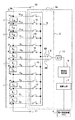
図1は、本発明の実施の形態に係る電源装置の回路図である。図1の電源装置は、n個(nは2以上の整数)の電池モジュール1を直列に接続して構成される走行用バッテリ2と、この走行用バッテリ2に備えられる各々の電池モジュール1の電圧を検出する電圧検出回路3と、この電圧検出回路3で検出された各々の電池モジュール1の電圧から電池状態を判別して、走行用バッテリ2の充放電を制御する電子制御装置(ECU;Electronic Control Unit)4と、を備える。上記電池状態とは、各々の電池モジュール1の状態又は、走行用バッテリ2に含まれる電池モジュール1の総合的な状態である。
FIG. 1 is a circuit diagram of a power supply device according to an embodiment of the present invention. The power supply device of FIG. 1 includes a traveling
走行用バッテリ2は、たとえば50個の電池モジュール1を直列に接続して構成される。ただ、走行用バッテリは、50個より少なく、あるいは50個よりも多くの電池モジュールを直列に接続することもできる。全ての電池モジュール1の電圧は電圧検出回路3によって検出される。各々の電池モジュール1は、5個の二次電池(例えば、ニッケル水素電池;不図示)を直列に接続したものから構成される。
The traveling
50個の電池モジュール1を直列に接続して構成される走行用バッテリ2は、全体で250個の二次電池を直列に接続して構成されることになり、その出力電圧は300V程度となる。各々の電池モジュール1は、必ずしも5個の二次電池を直列に接続して構成されるものではなく、たとえば、4個以下、あるいは6個以上の二次電池を直列に接続して構成されてもよい。さらに、各々の電池モジュール1は、1個の二次電池で構成されていてもよい。また、二次電池として、リチウムイオン二次電池やニッケルカドミウム電池など、充電可能な全ての電池を使用可能である。
The traveling
図1の電源装置において、走行用バッテリ2において最も低電圧側に配置される電池モジュール1と走行用バッテリ2のマイナス側の出力端子21との接続点をP0とし、走行用バッテリ2において最も高電圧側に配置される電池モジュール1と走行用バッテリ2のプラス側の出力端子22との接続点をPnとする。P0からPnに向かって順番に各電池モジュール1間の接続点を、電池接続点P1、P2、P3、・・・、Pn-4、Pn-3、Pn-2、Pn-1と呼ぶ。また、Pnも電池接続点Pnと呼ぶ。また、P0も電池接続点P0と呼ぶことができるのであるが、図1の電源装置においては、P0を特に基準接続点と呼ぶ。但し、後述する図2の説明においては、P0を電池接続点と呼ぶことがある。また、以下の説明において、電池接続点P1、P2、P3、・・・、Pn-4、Pn-3、Pn-2、Pn-1及びPnを、電池接続点P1〜Pnと表記する。
In the power supply device of FIG. 1, the connection point between the
電圧検出回路3は、各電池接続点の相対電圧を検出する電圧検出部5と、電圧検出部5にて検出された相対電圧の夫々が、誤検出電圧と正常検出電圧のどちらであるかを相対電圧ごとに判定する誤検出判定部6と、検出された相対電圧に基づいて各々の電池モジュール1の電圧を演算する演算回路7と、を備える。
The
電圧検出部5は、基準接続点P0に対する電池接続点P1〜Pnの相対電圧の夫々を、順番に検出する。電圧検出部5は、入力側に電池接続点P1、P2、・・・、Pn-1及びPnが接続されたマルチプレクサ9と、差動アンプ8を有しており、差動アンプ8にて各相対電圧が検出される。マルチプレクサ9は、n個のスイッチング素子10を有しており、電池接続点P1〜Pnの夫々は、互いに異なる1つのスイッチング素子10の入力端子に接続されている。全てのスイッチング素子10の出力端子は共通接続されると共に、マルチプレクサ9の出力端子(出力側)に接続されている。
The
差動アンプ8の第1の入力端子8A(例えば、反転入力端子)は基準接続点P0に接続されている。差動アンプ8の第2の入力端子8B(例えば、非反転入力端子)はマルチプレクサ9の出力端子に接続されている。つまり、差動アンプ8の第2の入力端子8Bは、マルチプレクサ9を介して電池接続点P1〜Pnの夫々に接続されている。マルチプレクサ9は、所定の周期で順番に1つのスイッチング素子10をオンにして、電池接続点P1〜Pnの夫々を順次、差動アンプ8の第2の入力端子8Bに接続する。つまり、差動アンプ8は、基準接続点P0に対する電池接続点P1〜Pnの各相対電圧を順番に検出することになる。
The
電圧検出部5によって検出された電池接続点P1、P2、P3、・・・、Pn-4、Pn-3、Pn-2、Pn-1及びPnにおける相対電圧を、夫々、相対電圧V1、V2、V3、・・・、Vn-4、Vn-3、Vn-2、Vn-1及びVnと表記する。また、以下の説明において、相対電圧V1、V2、V3、・・・、Vn-4、Vn-3、Vn-2、Vn-1及びVnを、相対電圧V1〜Vnと表記する。尚、基準接続点P0における相対電圧V0は、勿論0Vとなる。
Relative voltages at battery connection points P 1 , P 2 , P 3 ,..., P n-4 , P n-3 , P n-2 , P n-1 and P n detected by the
また、基準接続点P0と電池接続点P1の双方に直接接続される電池モジュール1の電圧、電池接続点P1と電池接続点P2の双方に直接接続される電池モジュール1の電圧、電池接続点P2と電池接続点P3の双方に直接接続される電池モジュール1の電圧、・・・、電池接続点Pn-4と電池接続点Pn-3の双方に直接接続される電池モジュール1の電圧、電池接続点Pn-3と電池接続点Pn-2の双方に直接接続される電池モジュール1の電圧、電池接続点Pn-2と電池接続点Pn-1の双方に直接接続される電池モジュール1の電圧、及び電池接続点Pn-1と電池接続点Pnの双方に直接接続される電池モジュール1の電圧を、それぞれ、電池モジュール電圧E1、E2、E3、・・・、En-3、En-2、En-1及びEnと呼ぶ。また、以下の説明において、電池モジュール電圧E1、E2、E3、・・・、En-3、En-2、En-1及びEnを、電池モジュール電圧E1〜Enと表記する。
Further, the voltage of the
差動アンプ8の出力側はA/Dコンバータ11に接続されている。A/Dコンバータ11は、差動アンプ8から出力されるアナログの相対電圧V1〜Vnをデジタル信号の相対電圧に変換する。A/Dコンバータ11にて変換されたデジタル信号の相対電圧は、誤検出判定部6に伝送される。差動アンプ8の出力をA/Dコンバータ11にてデジタル信号に変換する場合、誤検出判定部6は、そのデジタル信号をデジタル処理して誤検出電圧に関する判定を行い、また、演算回路7もデジタル処理して各々の電池モジュール1の電圧を演算する。誤検出判定部6は、必ずしもデジタル処理にて誤検出電圧に関する判定を行う必要はなく、アナログ処理にて誤検出電圧に関する判定を行ってもよい。このため、A/Dコンバータ11を介することなく、差動アンプ8の出力を誤検出判定部6に直接与えるようにしても構わない(不図示)。
The output side of the
誤検出判定部6は、電圧検出部5によって次々と検出される相対電圧V1〜Vnが、正常検出電圧と誤検出電圧のどちらであるかを相対電圧ごとに判定する。誤検出判定部6は、図示されないメモリに記憶されている電池モジュール1の最低電圧VLと最高電圧VHとを用いて、検出された相対電圧が誤検出電圧であるか否かを判定する。電池モジュール1の最低電圧VLとは、例えば、電池モジュール1の電圧として予想される(或いは許容される)最低の電圧を示すものである。電池モジュール1の最高電圧VHとは、例えば、電池モジュール1の電圧として予想される(或いは許容される)最高の電圧を示すものである。
The erroneous
たとえば、オンとするスイッチング素子10を順番に切り換えることにより、差動アンプ8の第2の入力端子8Bに接続される電池接続点を、電池接続点P1側から電池接続点Pn側に向かって順番に切り換えた場合、次々と差動アンプ8にて検出される相対電圧は、前回に検出された相対電圧に1個の電池モジュール1の電圧を加算した電圧となる。いいかえると、次回に測定される電池接続点の相対電圧から1個の電池モジュール1の電圧を減算した値が前回に検出される相対電圧となる。検出された各相対電圧が正常な場合(又は正常とみなされる場合)、1個の電池モジュール1の電圧範囲は、最低電圧VLと最高電圧VHとで特定される範囲内にあるはずである。
For example, by switching the switching
したがって、検出された相対電圧が、前回に検出された相対電圧に1個の電池モジュール1の電圧を加算した電圧範囲内にあれば、正常検出電圧と判定され、その範囲内になければ誤検出電圧と判定する。即ち、例えば、不等式:(電池モジュール1の最低電圧VL)≦(V2−V1)≦(電池モジュール1の最高電圧VH)が成立する場合、検出された相対電圧V2は正常検出電圧と判定され、不成立の場合、検出された相対電圧V2は誤検出電圧と判定される。同様にして、不等式:(電池モジュール1の最低電圧VL)≦(V3−V2)≦(電池モジュール1の最高電圧VH)が成立する場合、検出された相対電圧V3は正常検出電圧と判定され、不成立の場合、検出された相対電圧V3は誤検出電圧と判定される。尚、上記の2つの不等式の記号“≦”は“<”に置換しても構わない。
Therefore, if the detected relative voltage is within the voltage range obtained by adding the voltage of one
また、検出された相対電圧が、次回に検出される相対電圧から1個の電池モジュール1の電圧を減算した電圧範囲内にあれば、正常検出電圧と判定し、その範囲内になければ誤検出電圧と判定することもできる。即ち、例えば、不等式:(電池モジュール1の最低電圧VL)≦(V2−V1)≦(電池モジュール1の最高電圧VH)が成立する場合、検出された相対電圧V1は正常検出電圧と判定され、不成立の場合、検出された相対電圧V1は誤検出電圧と判定される。同様にして、不等式:(電池モジュール1の最低電圧VL)≦(V3−V2)≦(電池モジュール1の最高電圧VH)が成立する場合、検出された相対電圧V2は正常検出電圧と判定され、不成立の場合、検出された相対電圧V2は誤検出電圧と判定される。尚、上記の2つの不等式の記号“≦”は“<”に置換しても構わない。
Also, if the detected relative voltage is within the voltage range obtained by subtracting the voltage of one
たとえば、電池接続点Pn-2とマルチプレクサ9の入力側とを接続するリード線(検出線)が断線した(或いは、そのリード線間に介在する図示されないコネクタが接触不良になった)と仮定する。この場合、電池接続点Pn-2はマルチプレクサ9の入力側に接続されなくなって、検出される相対電圧Vn-2は、正常範囲(正常検出電圧と判定される電圧の範囲)よりも低くなり誤検出電圧と判定される。本来、電池接続点Pn-2から検出される相対電圧Vn-2は、電池接続点Pn-3から検出される相対電圧Vn-3に、電池モジュール電圧En-2を加算した電圧となる。通常、電池モジュール電圧En-2は、電池モジュール1の最低電圧VLと最高電圧VHの範囲にある。
For example, it is assumed that a lead wire (detection wire) connecting the battery connection point P n-2 and the input side of the multiplexer 9 is disconnected (or a connector (not shown) interposed between the lead wires has a poor contact). To do. In this case, the battery connection point P n−2 is not connected to the input side of the multiplexer 9, and the detected relative voltage V n−2 is lower than the normal range (the voltage range determined as the normal detection voltage). It is determined as a false detection voltage. Originally, the relative voltage V n-2 detected from the battery connection point P n-2 is the relative voltage V n-3 detected from the battery connection point P n-3, the sum of the battery module voltage E n-2 Voltage. Usually, the battery module voltage En -2 is in the range of the lowest voltage V L and the highest voltage V H of the
したがって、電池接続点Pn-2から検出される相対電圧Vn-2の正常範囲は、例えば、“(検出された相対電圧Vn-3)+(電池モジュール電圧En-2の最低電圧)”以上、且つ“(検出された相対電圧Vn-3)+(電池モジュール電圧En-2の最高電圧)”以下となる。上記のような断線等が発生すると、電池接続点Pn-2から検出される相対電圧Vn-2が、この正常範囲から外れることになり、検出された相対電圧Vn-2は誤検出電圧であると判定される(尚、この範囲内にある場合は正常検出電圧と判定される)。 Accordingly, the normal range of the relative voltage V n−2 detected from the battery connection point P n−2 is, for example, “(the detected relative voltage V n−3 ) + (the lowest voltage of the battery module voltage E n−2 ). ) ”Or more and“ (the detected relative voltage V n−3 ) + (the highest voltage of the battery module voltage E n−2 ) ”or less. When the disconnection or the like as described above occurs, the relative voltage V n-2 detected from the battery connection point P n-2 deviates from this normal range, and the detected relative voltage V n-2 is erroneously detected. It is determined that the voltage is within the range (when it is within this range, it is determined as the normal detection voltage).
また、電池接続点Pn-2から検出される相対電圧Vn-2が正常検出電圧と判定される範囲は、電池接続点Pn-1の相対電圧Vn-1からも特定することができる。この場合、相対電圧Vn-2の正常範囲は、相対電圧Vn-1から電池モジュール電圧En-1を減算した電圧となる。電池モジュール電圧En-1は、電池モジュール1の最低電圧VLと最高電圧VHの範囲にあるので、電池接続点Pn-2から検出される相対電圧Vn-2の正常範囲は、例えば、“(検出された相対電圧Vn-1)−(電池モジュール電圧En-1の最高電圧)”以上、且つ“(検出された相対電圧Vn-1)−(電池モジュール電圧En-1の最低電圧)”以下となる。検出された相対電圧Vn-2が、この正常範囲にあると、検出された相対電圧Vn-2は正常検出電圧と判定され、この範囲にないと誤検出電圧と判定される。
Further, the range in which the relative voltage V n−2 detected from the battery connection point P n−2 is determined as the normal detection voltage can also be specified from the relative voltage V n−1 at the battery connection point P n−1. it can. In this case, the normal range of the relative voltage V n−2 is a voltage obtained by subtracting the battery module voltage E n−1 from the relative voltage V n−1 . Since the battery module voltage E n-1 is in the range between the lowest voltage V L and the highest voltage V H of the
また、不等式:(q×最低電圧VL)≦検出された相対電圧Vq≦(q×最高電圧VH)が成立する場合(但し、qは1〜nの任意の整数)、検出された相対電圧Vqが正常検出電圧であると判定され、不成立の場合、検出された相対電圧Vqが誤検出電圧であると判定されるようにしてもよい。尚、この不等式の記号“≦”は“<”に置換しても構わない。特に、検出された相対電圧Vqが最低電圧未満となることにより誤検出と判定される場合は、検出線の断線不良、検出回路における検出線等の接触不良が発生していることが多い。 In addition, if the inequality: (q × lowest voltage V L ) ≦ detected relative voltage V q ≦ (q × highest voltage V H ) is satisfied (where q is an arbitrary integer from 1 to n), it was detected. If the relative voltage V q is determined to be a normal detection voltage and is not established, it may be determined that the detected relative voltage V q is an erroneous detection voltage. Note that the symbol “≦” in the inequality may be replaced with “<”. In particular, when the detected relative voltage Vq is less than the minimum voltage and it is determined that there is a false detection, a detection line disconnection failure or a contact failure such as a detection line in the detection circuit often occurs.
また、以下の説明においては、qは、特記なき限り、1〜(n−1)の任意の整数であるとする(qはnと等しくならない)。 In the following description, q is an arbitrary integer from 1 to (n-1) unless otherwise specified (q is not equal to n).
検出された相対電圧Vqが誤検出電圧であると判定されると、演算回路7は誤検出電圧が検出された電池接続点Pqにおけるリカバリ電圧VRqを算出する。相対電圧Vq、電池接続点Pq及びリカバリ電圧VRqの表記中の“q”は、上述の如く、1〜(n−1)の任意の整数をとる。例えば、検出された相対電圧V1が誤検出電圧であると判定されると、電池接続点P1におけるリカバリ電圧VR1を算出する。 If it is determined that the detected relative voltage V q is a false detection voltage, the arithmetic circuit 7 calculates a recovery voltage VR q at the battery connection point P q where the false detection voltage is detected. “Q” in the notation of the relative voltage V q , the battery connection point P q, and the recovery voltage VR q takes an arbitrary integer of 1 to (n−1) as described above. For example, if the relative voltages V 1 detected it is determined to be a false detection voltages to calculate the recovery voltage VR 1 in the battery connection point P 1.
以下の説明において、“電圧検出部5によって検出された相対電圧であって、誤検出判定部6によって誤検出電圧と判定された相対電圧”を、単に“誤検出された相対電圧”というものとする。リカバリ電圧VRqは、電池接続点Pqにおける推定された相対電圧というべきものであり、演算回路7は、誤検出された相対電圧Vqをリカバリ電圧VRqに置き換えて、電池モジュール電圧E1〜Enを算出する。換言すれば、演算回路7は、リカバリ電圧VRqを検出された相対電圧Vqとみなして電池モジュール電圧E1〜Enを算出するとも言える。より詳しくは、演算回路7は、誤検出された相対電圧Vqをリカバリ電圧VRqに置き換えて電池モジュール電圧Eq及びEq+1を算出する。又は、演算回路7は、誤検出された相対電圧Vqをリカバリ電圧VRqに置き換えて電池モジュール電圧Eq及びEq+1の何れか一方を算出する。
In the following description, “relative voltage detected by the
リカバリ電圧は、誤検出電圧が検出された電池接続点のプラス側とマイナス側に隣接する2つの電池接続点から検出された正常検出電圧(正常検出電圧と判定された相対電圧)を等分に分割することにより算出される。演算回路7は、演算したリカバリ電圧を誤検出電圧に代わって電池接続点の相対電圧とし、電池モジュール1の電圧を演算する。
The recovery voltage is divided equally between the normal detection voltage (relative voltage determined to be normal detection voltage) detected from the two battery connection points adjacent to the positive side and negative side of the battery connection point where the false detection voltage was detected. Calculated by dividing. The arithmetic circuit 7 calculates the voltage of the
例えば、1つの電池接続点Pn-2から検出される相対電圧Vn-2が誤検出電圧であると判定されると、演算回路7は、電池接続点Pn-2のプラス側に隣接する電池接続点Pn-1の相対電圧Vn-1と、マイナス側に隣接する電池接続点Pn-3の相対電圧Vn-3を加算平均することにより、電池接続点Pn-2のリカバリ電圧VRn-2を算出し、算出されたリカバリ電圧VRn-2を用いて電池モジュール電圧En-1と電池モジュール電圧En-2を算出する。つまり、誤検出された相対電圧Vn-2をリカバリ電圧VRn-2に置き換えて電池モジュール電圧En-1及びEn-2を算出するのである。加算平均して算出されるリカバリ電圧VRn-2は、以下の式(1)にて演算される。但し、相対電圧Vn-1と相対電圧Vn-3は、正常検出電圧と判定されているものとする。
VRn-2=(Vn-1+Vn-3)/2 ・・・(1)
For example, if it is determined that the relative voltage V n−2 detected from one battery connection point P n−2 is a false detection voltage, the arithmetic circuit 7 is adjacent to the positive side of the battery connection point P n−2. the relative voltage V n-1 of the battery connection point P n-1 which, by averaging the relative voltage V n-3 of the battery connection point P n-3 which is adjacent to the negative side, the battery connection point P n-2 recovery voltage calculating the VR n-2, with a recovery voltage VR n-2, which is calculated to calculate a battery module voltage E n-1 and the battery module voltage E n-2 of the. In other words, the battery module voltages En -1 and En -2 are calculated by replacing the erroneously detected relative voltage Vn -2 with the recovery voltage VRn -2 . The recovery voltage VR n−2 calculated by averaging is calculated by the following equation (1). However, it is assumed that the relative voltage V n-1 and the relative voltage V n-3 are determined as normal detection voltages.
VR n-2 = (V n-1 + V n-3 ) / 2 (1)
また、任意の電池接続点Pqにおいて検出された相対電圧Vqが誤検出電圧と判定された場合、対応するリカバリ電圧VRqは、下記式(2)にて算出される。
VRq=(Vq+1+Vq-1)/2 ・・・(2)
When the relative voltage V q detected at an arbitrary battery connection point P q is determined to be a false detection voltage, the corresponding recovery voltage VR q is calculated by the following equation (2).
VR q = (V q + 1 + V q-1 ) / 2 (2)
上記式(2)は、下式(3)に変形することができる。つまり、リカバリ電圧VRqは、「検出された相対電圧Vqが誤検出電圧と判定された電池接続点Pqのマイナス側に隣接する電池接続点Pq-1の相対電圧Vq-1」に、「電池接続点Pqのプラス側とマイナス側に隣接する2つの電池接続点Pq-1及びPq+1から検出される相対電圧Vq+1、Vq-1の差電圧を2等分した値」を、加えた値として算出される。また、上記式(2)は、下式(4)に変形することもできる。つまり、リカバリ電圧VRqは、「検出された相対電圧Vqが誤検出電圧と判定された電池接続点Pqのプラス側に隣接する電池接続点Pq+1の相対電圧Vq+1」から、「電池接続点Pqのプラス側とマイナス側に隣接する2つの電池接続点Pq-1及びPq+1から検出される相対電圧Vq+1、Vq-1の差電圧を2等分した値」を、差し引いた値として算出される。
VRq=Vq-1+(Vq+1−Vq-1)/2 ・・・(3)
VRq=Vq+1−(Vq+1−Vq-1)/2 ・・・(4)
The above equation (2) can be transformed into the following equation (3). That is, the recovery voltage VR q is "relative voltage V q-1 of the battery connection point P q-1 which is adjacent to the negative side of the detected relative voltage V q is erroneously detected voltage and the determined battery connection point P q" in the positive and the
VR q = V q-1 + (V q + 1 -V q-1 ) / 2 (3)
VR q = V q + 1 − (V q + 1 −V q−1 ) / 2 (4)
上記式(2)、(3)及び(4)の何れを用いても、リカバリ電圧VRqは、相対電圧Vq+1とVq-1の平均値となる。つまり、演算回路7は、リカバリ電圧VRqが相対電圧Vq+1とVq-1の平均値となるように、リカバリ電圧VRqを算出するのである。但し、上記式(2)、(3)及び(4)等によるリカバリ電圧VRqの算出において、相対電圧Vq+1と相対電圧Vq-1は、正常検出電圧と判定されているとする。 The recovery voltage VR q is an average value of the relative voltages V q + 1 and V q−1 regardless of which of the above formulas (2), (3), and (4). That is, the arithmetic circuit 7 calculates the recovery voltage VR q so that the recovery voltage VR q becomes an average value of the relative voltages V q + 1 and V q−1 . However, it is assumed that the relative voltage V q + 1 and the relative voltage V q-1 are determined as normal detection voltages in the calculation of the recovery voltage VR q by the above formulas (2), (3), and (4). .
誤検出判定部6が誤検出電圧の存在を検出すると、電圧検出回路3(具体的には、例えば誤検出判定部6又は演算回路7)は、電子制御装置4に、電池モジュール電圧を正常に検出できなかったことを示す検出不良信号を出力する。例えば、1つの誤検出電圧が検出されるごとに、1つの検出不良信号が出力される。電源装置は、各々の電池接続点の相対電圧の差から各々の電池モジュール電圧を演算する。このため、ひとつの電池接続点から誤検出電圧が検出されると、この電池接続点のプラス側とマイナス側に接続されている2個の電池モジュール1の電圧を演算できなくなることが考えられる。しかしながら、図1の電源装置においては、誤検出電圧が検出された電池接続点の相対電圧はリカバリー電圧で置換されるので、誤検出に係る電池接続点に接続されている両方の電池モジュール1の電圧を算出可能となる。
When the erroneous
電圧検出回路3は、誤検出電圧が検出されたとき、リカバリ電圧を用いて誤検出に係る電池接続点に直接接続されている両方の電池モジュール1の電圧を算出すると共に、上記検出不良信号を電子制御装置4に出力する。電圧検出回路3は、検出不良信号と一緒に、相対電圧を正常に検出できなかった電池接続点を特定する信号、あるいは誤検出電圧と判定された相対電圧からは電池モジュール電圧を検出することができない電池モジュール1を特定する信号を電子制御装置4に出力する。
When an erroneous detection voltage is detected, the
例えば、検出された相対電圧Vn-1及び相対電圧Vn-3が正常検出電圧であり、且つ検出された相対電圧Vn-2が誤検出電圧であると判定された場合、演算回路7が上記式(2)、(3)又は(4)等を用いてリカバリ電圧VRn-2を算出するとともに、誤検出判定部6又は演算回路7が検出不良信号と一緒に、“相対電圧が正常に検出できなかった電池接続点が電池接続点Pn-2であることを特定する信号”又は“検出された相対電圧Vn-2に基づいて電池モジュール電圧を検出できない電池モジュール1が、電池接続点Pn-2に直接接続された2つの電池モジュール1であることを特定する信号”を、電子制御装置4に出力する。
For example, when it is determined that the detected relative voltage V n-1 and the relative voltage V n-3 are normal detection voltages and the detected relative voltage V n-2 is a false detection voltage, the arithmetic circuit 7 Calculates the recovery voltage VR n−2 using the above formula (2), (3) or (4), etc., and the erroneous
また、上記のプロセスに代えて、以下のような他のプロセスを採用しても良い。この他のプロセスにおいては、演算回路7が、誤検出電圧が検出された電池接続点に直接接続された一対の電池モジュール1の内、一方の電池モジュール1の電圧をリカバリ電圧に基づいて算出し、電圧検出回路3(具体的には、例えば誤検出判定部6又は演算回路7)が、他方の電池モジュール1の電圧が検出不良であることを電子制御装置4に伝達する。その後、電子制御装置4又は電子制御装置4の後段に設けられる図示されない装置等において、他方の電池モジュール1の電圧が、リカバリ電圧を用いて算出された一方の電池モジュール1の電圧と同じであると処理する。
Further, instead of the above process, other processes as described below may be adopted. In this other process, the arithmetic circuit 7 calculates the voltage of one of the
例えば、検出された相対電圧Vn-1及び相対電圧Vn-3が正常検出電圧であり、且つ検出された相対電圧Vn-2が誤検出電圧であると判定された場合、演算回路7が上記式(2)、(3)又は(4)等を用いてリカバリ電圧VRn-2を算出し、誤検出電圧が検出された電池接続点Pn-2のプラス側に接続された電池モジュール1の電池モジュール電圧En-1を、式“En-1=Vn-1−VRn-2”によって算出する。そして、電圧検出回路3(具体的には、例えば誤検出判定部6又は演算回路7)が、誤検出電圧が検出された電池接続点Pn-2のマイナス側に接続された電池モジュール1の電池モジュール電圧En-2が検出不良であることを電子制御装置4に伝達する。その後、電子制御装置4又は電子制御装置4の後段に設けられる図示されない装置等において、電池モジュール電圧En-2が、電池モジュール電圧En-1と同じであると処理するのである。
For example, when it is determined that the detected relative voltage V n-1 and the relative voltage V n-3 are normal detection voltages and the detected relative voltage V n-2 is a false detection voltage, the arithmetic circuit 7 Calculates the recovery voltage VR n-2 using the above formula (2), (3) or (4), etc., and the battery connected to the positive side of the battery connection point P n-2 where the false detection voltage is detected The battery module voltage E n-1 of the
尚、電圧検出回路3は、誤検出電圧が検出された電池接続点に接続されている電池モジュール1の電圧をリカバリ電圧から演算すると共に、演算した電池モジュール1の電圧と検出不良信号とを、交互に電子制御装置4に出力する。
The
電子制御装置4は、電圧検出回路3から与えられる検出不良信号に基づいて、走行用バッテリ2の充放電を制御する。たとえば、検出不良信号の個数が少ない場合は、走行用バッテリ2の充放電電流を制限せず、検出不良信号の個数が所定の第1設定数よりも多くなった場合に、該充放電電流に制限を加える。更に、検出不良信号の個数が増加し、所定の第2設定数(>第1設定数)よりも多くなると、走行用バッテリ2の充放電電流を遮断する。
The electronic control unit 4 controls charging / discharging of the traveling
電圧検出回路3から電子制御装置4に伝送されるデジタル信号の通信コマンドにおいて、たとえば電池モジュールの電圧を14ビットのA/Dコンバータで検出し、検出した電圧の14ビットのデジタル信号を8ビット2バイト信号で伝送する場合、7ビットを電圧信号とし1ビットを識別ビット信号とするプロトコルで、このデジタル信号を伝送することができる。この場合、最初の1ビットを識別ビットとして伝送すると、受信側では最初の1ビットで伝送される信号を識別できる。
In the communication command of the digital signal transmitted from the
図1の電源装置(及び図2の電源装置)は、連続するC個(但し、Cは2以上の整数)の電池接続点から誤検出電圧が検出されても、各々の電池モジュール1の電圧を算出できる。それは、誤検出判定部6が誤検出電圧を検出したとき、演算回路7が、誤検出電圧が検出される電池接続点のプラス側とマイナス側に隣接する電池接続点から検出される相対電圧を等分に分割することによりリカバリ電圧を演算し、このリカバリ電圧を誤検出に係る相対電圧に置き換えて、電池モジュール1の電圧を演算するからである。
The power supply device of FIG. 1 (and the power supply device of FIG. 2) is configured to detect the voltage of each
例えば、互いに隣接する2点の電池接続点Pn-2及びPn-3から検出された相対電圧Vn-2及びVn-3が、双方、誤検出電圧と判定されると、演算回路7は、この2点の電池接続点Pn-2、Pn-3における相対電圧を、夫々、リカバリー電圧VRn-2、VRn-3として演算する。リカバリ電圧VRn-2、VRn-3は、誤検出電圧が検出された2点の電池接続点Pn-2及びPn-3のプラス側に隣接する電池接続点Pn-1の相対電圧Vn-1と、マイナス側に隣接する電池接続点Pn-4の相対電圧Vn-4を3等分して演算される。2点の電池接続点Pn-2、Pn-3のリカバリー電圧VRn-2、VRn-3は、3等分して演算されるので、以下の式で演算される。但し、相対電圧Vn-1及びVn-4は、正常検出電圧である。
VRn-2=Vn-4+2(Vn-1−Vn-4)/3
VRn-3=Vn-4+ (Vn-1−Vn-4)/3
For example, when the relative voltages V n−2 and V n−3 detected from two battery connection points P n−2 and P n−3 adjacent to each other are both determined as false detection voltages, the arithmetic circuit 7 calculates the relative voltages at the two battery connection points P n−2 and P n−3 as recovery voltages VR n−2 and VR n−3 , respectively. The recovery voltages VR n−2 and VR n−3 are relative to the battery connection point P n−1 adjacent to the positive side of the two battery connection points P n−2 and P n−3 where the false detection voltage is detected. The voltage V n-1 and the relative voltage V n-4 of the battery connection point P n-4 adjacent to the negative side are divided into three equal parts and calculated. Since the recovery voltages VR n−2 and VR n−3 at the two battery connection points P n−2 and P n−3 are calculated by dividing into three equal parts, the following expressions are used. However, the relative voltages V n-1 and V n-4 are normal detection voltages.
VR n−2 = V n−4 +2 (V n−1 −V n−4 ) / 3
VR n-3 = V n-4 + (V n-1 −V n-4 ) / 3
互いに隣接する、即ち連続するC個の電池接続点Pq、Pq+1、・・・、Pq+C-2及びPq+C-1から検出される相対電圧Vq、Vq+1、・・・、Vq+C-2及びVq+C-1が全て誤検出電圧と判定されたとき、演算回路7は、リカバリ電圧VRq、VRq+1、・・・、VRq+C-2及びVRq+C-1を、以下のC個からなる式(5)を用いて算出する。 Relative voltages V q , V q + detected from adjacent C battery connection points P q , P q + 1 ,..., P q + C-2 and P q + C−1. 1 ,..., V q + C-2 and V q + C-1 are all determined to be false detection voltages, the arithmetic circuit 7 determines that the recovery voltages VR q , VR q + 1 ,. q + C-2 and VR q + C-1 are calculated using the following equation (5) consisting of C pieces.
VRq =Vq-1 +(Vq+C−Vq-1)/(C+1)
VRq+1 =VRq +(Vq+C−Vq-1)/(C+1)
・ ・ ・ ・ ・
・ ・ ・ ・ ・
VRq+C-2=VRq+C-3+(Vq+C−Vq-1)/(C+1)
VRq+C-1=VRq+C-2+(Vq+C−Vq-1)/(C+1) ・・・(5)
VR q = V q-1 + (V q + C -V q-1) / (C + 1)
VR q + 1 = VR q + (V q + C -V q-1) / (C + 1)
・ ・ ・ ・ ・ ・
・ ・ ・ ・ ・ ・
VRq + C-2 = VRq + C-3 + ( Vq + C- Vq -1 ) / (C + 1)
VRq + C-1 = VRq + C-2 + ( Vq + C- Vq -1 ) / (C + 1) (5)
つまり、C個の電池接続点Pq〜Pq+C-1の接続点群に隣接する2つの電池接続点Pq-1及びPq+Cから検出される相対電圧Vq-1、Vq+C間の電圧を、基準電圧点P0における電位を基準として(C+1)等分し、その(C+1)等分して得られるC個の電圧のそれぞれを、マイナス側から、リカバリ電圧VRq、VRq+1、・・・、VRq+C-2及びVRq+C-1とするのである。但し、相対電圧Vq-1及びVq+Cは、正常検出電圧と判定された相対電圧であり、また、不等式:q+C≦n、が成立するものとする。尚、q=1の場合、相対電圧Vq-1は相対電圧V0(即ち、0V)と等しい。 That is, relative voltages V q-1 and V detected from two battery connection points P q-1 and P q + C adjacent to the connection point group of C battery connection points P q to P q + C-1. The voltage between q + C is divided into (C + 1) equal parts with reference to the potential at the reference voltage point P 0 , and each of the C voltages obtained by dividing the (C + 1) equal parts from the negative side is recovered voltage VR. q , VR q + 1 ,..., VR q + C-2 and VR q + C-1 . However, the relative voltages V q−1 and V q + C are relative voltages determined to be normal detection voltages, and the inequality: q + C ≦ n is established. When q = 1, the relative voltage V q-1 is equal to the relative voltage V 0 (that is, 0 V).
演算回路7は、誤検出された相対電圧Vq、Vq+1、・・・、Vq+C-2及びVq+C-1を、夫々リカバリ電圧VRq、VRq+1、・・・、VRq+C-2及びVRq+C-1に置き換えて、電池モジュール電圧E1〜Enを算出する。換言すれば、演算回路7は、リカバリ電圧VRq、VRq+1、・・・、VRq+C-2及びVRq+C-1を、それぞれ、検出された相対電圧Vq、Vq+1、・・・、Vq+C-2及びVq+C-1とみなして電池モジュール電圧E1〜Enを算出するとも言える。より詳しくは、演算回路7は、誤検出された相対電圧Vq、Vq+1、・・・、Vq+C-2及びVq+C-1を、夫々、リカバリ電圧VRq、VRq+1、・・・、VRq+C-2及びVRq+C-1に置き換えて電池モジュール電圧Eq、Eq+1、・・・、Eq+C-1及びEq+Cを算出する。 The arithmetic circuit 7 converts the erroneously detected relative voltages V q , V q + 1 ,..., V q + C-2 and V q + C−1 into recovery voltages VR q , VR q + 1 ,. The battery module voltages E 1 to E n are calculated in place of VR q + C-2 and VR q + C-1 . In other words, the arithmetic circuit 7 converts the recovery voltages VR q , VR q + 1 ,..., VR q + C-2 and VR q + C−1 into the detected relative voltages V q and V q , respectively. +1, ..., also regarded as a V q + C-2 and V q + C-1 to calculate the battery module voltage E 1 to E n say. More specifically, the arithmetic circuit 7 converts the erroneously detected relative voltages V q , V q + 1 ,..., V q + C-2 and V q + C−1 into the recovery voltages VR q and VR, respectively. q + 1, ···, VR q + C-2 and VR q + C-1 to replace the battery module voltage E q, E q + 1, ···, E q + C-1 and E q + C Is calculated.
連続するC個の電池接続点から検出された相対電圧が全て誤検出電圧と判定された場合も、電圧検出回路3は、電池モジュール電圧を正常に検出できなかったことを示す検出不良信号を、電子制御装置4に対して出力する。例えば、1つの誤検出電圧が検出されるごとに、1つの検出不良信号が出力される。この場合、電圧検出回路3は、誤検出電圧が検出された各電池接続点(例えば、Pn-2及びPn-3)に直接接続されている全ての電池モジュール電圧(例えば、En-1、En-2及びEn-3)を、各リカバリ電圧(例えば、VRn-2及びVRn-3)を用いて演算し、その演算した電池モジュール電圧を上記検出不良信号と共に電子制御装置4に出力する。この際、電圧検出回路3は、検出不良信号と一緒に、相対電圧を正常に検出できなかった電池接続点を特定する信号、あるいは誤検出電圧と判定された相対電圧からは電池モジュール電圧を検出することができない電池モジュール1を特定する信号を電子制御装置4に出力する。尚、電圧検出回路3は、誤検出電圧が検出された電池接続点に接続されている電池モジュール1の電圧をリカバリ電圧から演算すると共に、演算した電池モジュール1の電圧と検出不良信号とを、交互に電子制御装置4に出力する。
Even when all the relative voltages detected from the continuous C battery connection points are determined to be false detection voltages, the
また、上記のプロセスに代えて、以下のような他のプロセスを採用しても良い。連続する2つの電池接続点Pn-2及びPn-3から検出された相対電圧が誤検出電圧と判定された場合を例にとり、この他のプロセスを説明する。この他のプロセスにおいては、演算回路7が、リカバリ電圧VRn-3を用いて電池モジュール電圧En-3を算出する一方、電圧検出回路3(具体的には、例えば誤検出判定部6又は演算回路7)が、電池モジュール電圧En-2及びEn-1が検出不良であることを電子制御装置4に伝達する。その後、電子制御装置4又は電子制御装置4の後段に設けられる図示されない装置等において、電池モジュール電圧En-2及びEn-1が、リカバリ電圧VRn-3を用いて算出された電池モジュール電圧En-3と同じであると処理する。
Further, instead of the above process, other processes as described below may be adopted. This other process will be described by taking as an example a case where the relative voltage detected from two consecutive battery connection points P n-2 and P n-3 is determined as a false detection voltage. In this alternative process, the arithmetic circuit 7, while calculating the battery module voltage E n-3 using the recovery voltage VR n-3, the voltage detection circuit 3 (specifically, for example, the error
この場合においても、電子制御装置4は、電圧検出回路3から与えられる検出不良信号に基づいて、走行用バッテリ2の充放電を制御する。たとえば、検出不良信号の個数が少ない場合は、走行用バッテリ2の充放電電流を制限せず、検出不良信号の個数が所定の第1設定数よりも多くなった場合に、該充放電電流に制限を加える。更に、検出不良信号の個数が増加し、所定の第2設定数(>第1設定数)よりも多くなると、走行用バッテリ2の充放電電流を遮断する。
Also in this case, the electronic control unit 4 controls charging / discharging of the traveling
電圧検出回路3の演算回路7は、検出された各々の相対電圧V1〜Vnから、各々の電池モジュール電圧E1〜Enを算出する。電池モジュール電圧E1〜Enは、隣接する電池接続点間の電圧差となるので、以下のn個の等式から成る式(6)で演算される。誤検出判定部6によって全ての相対電圧V1〜Vnが正常検出電圧であると判断された場合は、検出された相対電圧V1〜Vnのみに基づいて、電池モジュール電圧E1〜Enが算出される。但し、検出された相対電圧Vqが誤検出電圧と判定された場合、上述の如く、その誤検出された相対電圧Vqをリカバリ電圧VRqに置き換えた上で、各々の電池モジュール電圧E1〜Enは算出される(上述の如く、qは1〜(n−1)の任意の整数)。
E1=V1
E2=V2−V1
E3=V3−V2
・ ・ ・
・ ・ ・
En-1=Vn-1−Vn-2
En=Vn−Vn-1 ・・・(6)
Arithmetic circuit of the
E 1 = V 1
E 2 = V 2 −V 1
E 3 = V 3 −V 2
・ ・ ・
・ ・ ・
E n-1 = V n-1 -V n-2
E n = V n −V n−1 (6)
また、任意の電池接続点Pqにおける相対電圧Vqが誤検出電圧であると判定されたとき、リカバリ電圧VRqは、上記式(2)等によって算出される。このとき、電池モジュール電圧Eqは、下式(7)にて表される。
Eq=VRq−Vq-1 ・・・(7)
Further, when it is determined that the relative voltage V q at any battery connection point P q is a false detection voltage, the recovery voltage VR q is calculated by the above equation (2) or the like. At this time, the battery module voltage E q is expressed by the following equation (7).
E q = VR q −V q−1 (7)
式(7)における相対電圧Vqをリカバリ電圧VRqに置き換えた上で、上記式(2)を代入すると、式(7)は下式(8)のようになる。
Eq=(Vq+1−Vq-1)/2 ・・・(8)
Substituting the above equation (2) after replacing the relative voltage V q in equation (7) with the recovery voltage VR q , equation (7) becomes the following equation (8).
E q = (V q + 1 −V q−1 ) / 2 (8)
つまり、必要なデータが電池モジュール電圧Eqであるなら、誤検出電圧が検出された電池接続点Eqに対するリカバリ電圧VRqを算出することなく、式(8)を用いて、電池モジュール電圧Eqを算出することができる。この場合、式(8)からも理解されるように、誤検出電圧が検出された電池接続点Pqに隣接する両電池接続点の相対電位の差を2等分してEqを演算する。そして、誤検出電圧が検出された電池接続点Pqに隣接する電池モジュール1の電池モジュール電圧EqとEq+1とが、等しいとする。つまり、Eq=Eq+1、とされる。
That is, if the necessary data is the battery module voltage E q , the battery module voltage E is calculated using the equation (8) without calculating the recovery voltage VR q for the battery connection point E q where the erroneous detection voltage is detected. q can be calculated. In this case, as can be understood from the equation (8), E q is calculated by equally dividing the difference between the relative potentials of both battery connection points adjacent to the battery connection point P q where the erroneous detection voltage is detected. . Assume that the battery module voltages E q and E q + 1 of the
更に、連続するC個の電池接続点Pq、Pq+1、・・・、Pq+C-2及びPq+C-1から検出された相対電圧が全て誤検出電圧と判定された場合、電池モジュール電圧Eq、Eq+1、・・・、Eq+C-1及びEq+Cは、下式(9)に基づいて算出される。但し、相対電圧Vq-1及びVq+Cは、正常検出電圧であり、また、不等式:q+C≦n、が成立するものとする。
Eq+C=Eq+C-1=・・・=Eq+1=Eq=(Vq+C−Vq-1)/(C+1) ・・・(9)
Furthermore, all the relative voltages detected from the continuous C battery connection points P q , P q + 1 ,..., P q + C-2 and P q + C-1 were determined to be false detection voltages. In this case, the battery module voltages E q , E q + 1 ,..., E q + C−1 and E q + C are calculated based on the following equation (9). However, the relative voltages V q-1 and V q + C are normal detection voltages, and the inequality: q + C ≦ n is established.
Eq + C = Eq + C-1 = ... = Eq + 1 = Eq = ( Vq + C- Vq -1 ) / (C + 1) (9)
つまり、連続するC個の電池接続点Pq〜Pq+C-1から成る接続点群のプラス側とマイナス側に隣接する2つの電池接続点Pq-1及びPq+Cから検出される相対電圧Vq-1、Vq+Cの差電圧に基づいて、電池接続点Pq〜Pq+C-1の各々に隣接する合計(C+1)個の電池モジュール1の電圧(即ち、電池モジュール電圧Eq〜Eq+C)を算出するのである。
That is, it is detected from two battery connection points P q-1 and P q + C adjacent to the positive side and the negative side of the connection point group consisting of consecutive C battery connection points P q to P q + C-1. Based on the difference voltage between the relative voltages V q-1 and V q + C , the voltage of the total (C + 1)
上記式(6)、式(8)又は式(9)を用いて算出された電池モジュール電圧E1〜Enは、電圧検出回路3(具体的には、演算回路7)から電子制御装置4に伝送される。電子制御装置4は、電池モジュール電圧E1〜Enを用いて、各々の電池モジュール1の残容量を演算する。この際、走行用バッテリ2の充放電電流に基づいて演算した残容量を補正してもよい。また、1又は2以上の電池モジュール1の電圧が最低電圧VLまで低下すると、充電を許容して放電を禁止し、反対に、1又は2以上の電池モジュール1の電圧が最高電圧VHまで上昇すると放電を許容して充電を禁止する。
The formula (6), equation (8) or the battery module voltage E 1 to E n, which is calculated using equation (9), (specifically, the arithmetic circuit 7) the
また、各相対電圧V1〜Vnを検出する手法の典型的な一例として、「オンとするスイッチング素子10を順番に切り換えることにより、差動アンプ8の第2の入力端子8Bに接続される電池接続点を、電池接続点P1側から電池接続点Pn側に向かって順番に切り換える手法」を説明したが、各相対電圧V1〜Vnを検出する順番はどのように変形してもよい。例えば、最初に相対電圧Vnー2、次に相対電圧V3、・・・、という順番にしても構わない。また、マルチプレクサ9と差動アンプ8(更にはA/Dコンバータ11)を、もう1組或いは複数組設けることにより、電池接続点の異なる複数の相対電圧を同時に検出するようにしても構わない。つまり、最終的に各相対電圧V1〜Vnを検出できるのなら、どのように回路構成を変形しても構わない。
Further, as a typical example of a technique for detecting each of the relative voltages V 1 to V n , “the switching
(図2;基準接続点の変形例)
図1の電源装置においては、走行用バッテリ2中の最も低電圧側にある接続点、即ち、P0を基準接続点としているが、基準接続点を他の電池接続点(P1〜Pnの任意の電池接続点)に定めても構わない。この場合、差動アンプ8の第1の入力端子8Aに接続される電池接続点が変更される。
(Fig. 2: Modified example of reference connection point)
In the power supply device of FIG. 1, the connection point on the lowest voltage side in the traveling
例えば、図1の電源装置を、図2の電源装置のように変形しても構わない。図2は、図1の電源装置を変形した電源装置の回路図である。図2において、図1と同一の部品には同一の符号を付してある。同一の符号を付した部品の構成及び動作は同じであるため、再度の説明を省略する。 For example, the power supply device of FIG. 1 may be modified as the power supply device of FIG. FIG. 2 is a circuit diagram of a power supply device obtained by modifying the power supply device of FIG. 2, the same components as those in FIG. 1 are denoted by the same reference numerals. Since the configuration and operation of the parts denoted by the same reference numerals are the same, the description thereof will be omitted.
図2の電源装置は、14個の電池モジュール1を直列に接続して構成される走行用バッテリ2aと、この走行用バッテリ2aに備えられる各々の電池モジュール1の電圧を検出する電圧検出回路3aと、電子制御装置4と、を備える。
The power supply device of FIG. 2 includes a traveling
図2における走行用バッテリ2aと電圧検出回路3aは、直列に接続された電池モジュール1の個数が具体化されている点、電池接続点P7がマルチプレクサ9を介することなく、差動アンプ8の第1の入力端子8Aに接続されている点、及び図1では基準接続点であったP0で表される接続点がマルチプレクサ9のスイッチング素子10を介してマルチプレクサ9の出力端子(出力側)及び差動アンプ8の第2の入力端子8Bに共通接続されている点以外は、構成及び動作とも図1における走行用バッテリ2と電圧検出回路3と同じである。
Driving
図2の電源装置においては、14個の電池モジュール1が夫々に接続されている電池接続点の中間点が、基準接続点とされている。つまり、14個の電池モジュール1の中央に位置する電池接続点P7を基準接続点としている。換言すれば、複数の電池接続点の中央の電池接続点P7を基準接続点としている。各電池接続点における相対電圧は、基準接続点の電位を基準とした電位であるため、図2に示す如く基準接続点を電池接続点P7とすると、電池接続点(基準接続点)P7よりもマイナス側の電池接続点P0、P1、P2、P3、P4、P5及びP6における各相対電圧V0、V1、V2、V3、V4、V5及びV6はマイナスの相対電圧として検出され、プラス側の電池接続点P8、P9、P10、P11、P12、P13及びP14における各相対電圧V8、V9、V10、V11、V12、V13及びV14はプラスの相対電圧として検出される。各々の電池モジュール1の電圧は、隣接する電池接続点から検出される相対電圧の差電圧として演算されるので、相対電圧がプラスであっても、マイナスであっても、各々の電池モジュール1の電圧(E0、E1、E2、E3、E4、E5、E6、E7、E8、E9、E10、E11、E12、E13及びE14)は算出可能である。図2の電源装置においても、図1の電源装置と同様に、上記式(2)〜式(9)を用いてリカバリ電圧や電池モジュール電圧が算出される。
In the power supply device of FIG. 2, an intermediate point between battery connection points to which each of the 14
尚、電池接続点(基準接続点)P7における相対電圧V7は、勿論0Vとなる。また、図2中において、電池接続点P4及びP10の記載は省略されており、これに伴い、図2中において、相対電圧V4及びV10並びに電池モジュール電圧E4、E5、E10及びE11の記号の表記は省略されている。 The relative voltage V 7 at the battery connection point (reference connection point) P 7 will of course be 0V. In FIG. 2, the description of the battery connection points P 4 and P 10 is omitted. Accordingly, in FIG. 2, the relative voltages V 4 and V 10 and the battery module voltages E 4 , E 5 , E The symbols 10 and E 11 are omitted.
本実施形態に関する以下の説明は、特記なき限り、図1の電源装置について行う。但し、以下の説明の全ては、図2の電源装置に対しても適用可能である。 The following description regarding the present embodiment will be made with respect to the power supply device of FIG. 1 unless otherwise specified. However, all of the following description can be applied to the power supply device of FIG.
(図3;動作フローチャート)
図1の電源装置の動作を示すフローチャートを、図3に示す。図3のフローチャートは、電圧検出回路3が電池モジュール電圧E1〜Enを検出する動作と、検出した電池モジュール電圧E1〜Enが電圧検出回路3から電子制御装置4に伝送される動作を示している。尚、図2の電源装置の動作も、図3で示される図1の電源装置の動作と同様である。
(Fig. 3; Operation flowchart)
FIG. 3 is a flowchart showing the operation of the power supply device of FIG. The flowchart of FIG. 3, the operation of the operation the
ステップS1において、電圧検出回路3は、各々の電池接続点P1〜Pnの相対電圧V1〜Vnを検出する。ステップS1を終えて移行するステップS2において、電圧検出回路3の演算回路7は、検出された相対電圧V1〜Vnが誤検出電圧であるか否かを、相対電圧ごとに判定する。ステップS2において、検出された相対電圧の何れかが誤検出電圧と判定されると、ステップS3に移行する(ステップS2のYes)。ステップS3において、誤検出電圧と判定された相対電圧に置換されるべきリカバリ電圧が算出された後、ステップS4に移行する。ステップS4において、電圧検出回路3は電子制御装置4に検出不良信号を伝送する。
In step S1, the
ステップS4を終えるとステップS5に移行する。また、ステップS2において誤検出電圧が検出されない場合(ステップS2のNo)も、ステップS5に移行する。ステップS5においては、相対電圧から、或いは相対電圧とリカバリ電圧から、各々の電池モジュール1の電圧が算出される。ステップS5を終えて移行するステップS6において、電圧検出回路3は、算出した各々の電池モジュール1の電圧を示す信号を電子制御装置4に伝送する。
When step S4 is completed, the process proceeds to step S5. Moreover, also when a false detection voltage is not detected in step S2 (No of step S2), it transfers to step S5. In step S5, the voltage of each
以上のS1〜S6のステップを一定の周期で繰り返し、電圧検出回路3から電子制御装置4に電池モジュール1の電圧を次々と伝送する。電子制御装置4は、電圧検出回路3から与えられる電池モジュール1の電圧に基づいて各々の電池モジュール1の状態を判定し、その判定結果に基づいて走行用バッテリ2(電池モジュール1)の充放電の電流を制御する。
The above steps S1 to S6 are repeated at a constant cycle, and the voltage of the
(図4及び図5;他の誤検出判定手法)
上述してきた誤検出判定部6による誤検出電圧と正常電圧電圧との区別は、電池モジュール1の最低電圧VL及び最高電圧VHを用いて行われる。各々の電池モジュール1が、5個のニッケル水素電池(不図示)を直列に接続したものから構成される場合、最低電圧VL及び最高電圧VHは、例えば、夫々1V、10Vに設定される。ところで、最低電圧VL及び最高電圧VHを用いて誤検出電圧と正常検出電圧とを区別する手法(以下、第1誤検出判定手法という)のみでは、比較的小さな相対電圧のずれを検出することができないことがある。つまり、或る相対電圧に比較的小さなのずれが発生していたとしても、第1誤検出判定手法のみでは、その相対電圧を正常検出電圧と判定してしまうことがある。このような比較的小さな相対電圧のずれは、相対電圧を検出するための検出線やコネクタ等において、接触不良が僅かに発生しているような場合に起こることが多い。
(FIGS. 4 and 5; other false detection determination methods)
The discrimination between the erroneous detection voltage and the normal voltage voltage by the erroneous
以下に、このような比較的小さな相対電圧のずれの有無を検出する手法(以下、第2誤検出判定手法という)を説明する。第2誤検出判定手法は、第1誤検出判定手法と組合せることが可能である。第2誤検出判定手法を第1誤検出判定手法と組み合わせた場合、誤検出判定部6は、第1誤検出判定手法によって各相対電圧が誤検出電圧及び正常検出電圧の何れであるかを検出するとともに、第1誤検出判定手法によって正常検出電圧と判定された相対電圧について再度、第2誤検出判定手法による判定を行う。そして、第1誤検出判定手法によって正常検出電圧と判定された相対電圧に、ずれが発生していると判断された場合、その相対電圧は最終的に誤検出電圧と判定される。第2誤検出判定手法によっても、ずれが発生していると判断されなかった場合、その相対電圧は最終的に正常検出電圧と判定される。尚、後述の説明から明らかとなるが、第2誤検出判定手法による判定を行うためには、電池モジュール1の電圧を知る必要がある。そのため、誤検出判定部6と演算回路7が協働して、第2誤検出判定手法を実行することになる。
Hereinafter, a method for detecting the presence or absence of such a relatively small relative voltage shift (hereinafter referred to as a second erroneous detection determination method) will be described. The second erroneous detection determination method can be combined with the first erroneous detection determination method. When the second erroneous detection determination method is combined with the first erroneous detection determination method, the erroneous
図1の電源装置において実行される第2誤検出判定手法について説明する。勿論、第2誤検出判定手法は図2の電源装置においても適用可能である。図4及び図5は、第2誤検出判定手法を説明するための図である。今、検出された相対電圧Vq-1、Vq及びVq+1から電池モジュール電圧Eq及びEq+1が、一旦算出されたとする。その一旦算出された電池モジュール電圧Eq及びEq+1の電圧が、それぞれE00及びE01であったとする。また、第1誤検出判定手法によって相対電圧Vq-1、Vq及びVq+1は、全て正常検出電圧であると判定されているとする。検出された相対電圧Vq-1及びVq+1は、真の相対電圧と等しく、ずれが発生していないものとする。但し、検出された相対電圧Vqには、相対電圧Vqを検出するための線路やコネクタ等における接触不良等によって、ずれが発生しており、検出された相対電圧Vqが真の相対電圧と異なる場合を想定する。 A second false detection determination method executed in the power supply device of FIG. 1 will be described. Of course, the second erroneous detection determination method can also be applied to the power supply apparatus of FIG. 4 and 5 are diagrams for explaining the second erroneous detection determination method. Assume that the battery module voltages E q and E q + 1 are once calculated from the detected relative voltages V q−1 , V q and V q + 1 . Assume that the once calculated battery module voltages E q and E q + 1 are E00 and E01, respectively. Further, it is assumed that the relative voltages V q−1 , V q, and V q + 1 are all determined to be normal detection voltages by the first erroneous detection determination method. It is assumed that the detected relative voltages V q−1 and V q + 1 are equal to the true relative voltage and no deviation occurs. However, the detected relative voltage V q is deviated due to a contact failure in a line or a connector for detecting the relative voltage V q , and the detected relative voltage V q is a true relative voltage. It is assumed that it is different from
図4においては、理解を助けるために、検出される相対電圧Vqの値がプラス側又はマイナス側に上下してずれることを上下の矢印でイメージ化している。検出された相対電圧Vqにずれが発生すると、検出された相対電圧Vqにずれが発生していない場合(正常時)と比べて、一方の電圧E01が大きくなると共に他方の電圧E00が小さくなったり(図5のずれ1参照)、一方の電圧E01が小さくなると共に他方の電圧E00が大きくなったり(図5のずれ2参照)する。つまり、電池モジュール電圧Eq及びEq+1が正確に検出されなくなる。
In FIG. 4, in order to help understanding, the value of the detected relative voltage V q is imaged by up and down arrows to shift up and down to the plus side or the minus side. The deviation of the detected relative voltage V q is generated, if a shift in the detected relative voltage V q is not generated compared to the (normal), small other voltage E00 with one voltage E01 is increased (See
第2誤検出判定手法においては、検出された相対電圧Vqにずれが発生しているか否かを以下のように判定する。まず、電圧E00と電池モジュール1の正常な電圧の平均電圧MMVの電圧偏差dif1、及び電圧E01と平均電圧MMVとの電圧偏差dif2を、下式(10)に従って算出する。ここで、平均電圧MMVとは、第1誤検出判定手法によって正常検出電圧と判定された相対電圧のみを用いて算出された電池モジュール1の電圧の平均値である。
dif1=E00−MMV
dif2=E01−MMV ・・・(10)
In the second erroneous detection determination method, it is determined as follows whether or not a deviation occurs in the detected relative voltage V q . First, the voltage deviation dif1 between the voltage E00 and the average voltage MMV of the normal voltage of the
dif1 = E00-MMV
dif2 = E01−MMV (10)
そして、電圧偏差dif1と電圧偏差dif2の何れかの絶対値が、所定の第1設定電圧(例えば、400mV)よりも大きいか否かを判定する。この判定を「判定1」という。電圧偏差dif1と電圧偏差dif2の何れかの絶対値が、所定の第1設定電圧よりも大きい場合、判定1は満たされる(肯定となる)。第1誤検出判定手法は、この第1設定電圧よりも大きな値で誤検出の有無を判定していることに相当するため、第1誤検出判定手法によって誤検出電圧と判定されない相対電圧におけるずれの有無が、判定1によって評価されることになる。
Then, it is determined whether or not the absolute value of any one of the voltage deviation dif1 and the voltage deviation dif2 is larger than a predetermined first set voltage (for example, 400 mV). This determination is referred to as “
次に、電圧偏差dif1と電圧偏差dif2の和の絶対値が所定の第2設定電圧(例えば、70mV)よりも小さいか否かを判定する。つまり、電圧E00と電圧E01の合計と平均電圧MMVの2倍値との差分の絶対値が第2設定電圧より小さいか否かを判定する。この判定を「判定2」という。電圧偏差dif1と電圧偏差dif2の和の絶対値が所定の第2設定電圧よりも小さい場合、判定2は満たされる(肯定となる)。判定2は、電圧E00と電圧E01に対応する電池モジュール1間で、相対電圧の検出のずれが発生しているのかを評価している。
Next, it is determined whether or not the absolute value of the sum of the voltage deviation dif1 and the voltage deviation dif2 is smaller than a predetermined second set voltage (for example, 70 mV). That is, it is determined whether or not the absolute value of the difference between the sum of the voltage E00 and the voltage E01 and the double value of the average voltage MMV is smaller than the second set voltage. This determination is referred to as “
上記判定1及び判定2の双方が満たされたとき、検出された相対電圧Vqにずれが発生していると判定する。つまり、第2誤検出判定手法によって、検出された相対電圧Vqが誤検出電圧であると判定される。一方、上記判定1及び判定2の双方が満たされないとき、第2誤検出判定手法によっても、検出された相対電圧Vqは正常検出電圧と判定される。
When both
第2誤検出判定手法によって、誤検出電圧と判定された相対電圧Vqに対しても、上記式(2)などを用いて、リカバリ電圧VRqが作成される。そして、検出された相対電圧Vqをリカバリ電圧VRqに置き換えた上で、上記式(6)に基づいて各々の電池モジュール1の最終的な電圧が算出される。また、第2誤検出判定手法によって、検出された相対電圧Vqが誤検出電圧と判定された場合、リカバリ電圧VRqを作成することなく、上記式(8)に基づいて各々の電池モジュール1の最終的な電圧を算出するようにしてもよい。この場合、誤検出電圧と判定された相対電圧Vqに対応する電池接続点Vqに隣接する電池モジュール1の電池モジュール電圧Eq及びEq+1は、双方、(Vq+1−Vq-1)/2、と等しいとされる。
The recovery voltage VR q is also created for the relative voltage V q determined to be an erroneous detection voltage by the second erroneous detection determination method using the above equation (2) or the like. Then, after replacing the detected relative voltage V q with the recovery voltage VR q , the final voltage of each
尚、この場合においても、式(2)の相対電圧を用いて、式(8)の電池モジュール電圧を算出している。従って、この電池モジュール電圧の算出法も、誤検出電圧が検出された電池接続点のプラス側とマイナス側に隣接する2つの電池接続点から検出される2つの相対電圧を等分に分割することによりリカバリ電圧を算出し、このリカバリ電圧を誤検出電圧が検出された電池接続点の相対電圧に置き換えて、電池モジュール電圧を算出する手法である、とも言うことができる。
(図6;端子の接続構造)
次に、各電池接続点P1〜Pnの相対電圧V1〜Vnを測定するための端子の接続構造について説明する。
In this case as well, the battery module voltage of Expression (8) is calculated using the relative voltage of Expression (2). Therefore, this battery module voltage calculation method also equally divides two relative voltages detected from two battery connection points adjacent to the positive side and the negative side of the battery connection point where the erroneous detection voltage is detected. It can also be said that this is a technique for calculating the battery voltage by replacing the recovery voltage with the relative voltage of the battery connection point where the erroneous detection voltage is detected.
(Fig. 6: Terminal connection structure)
Next, a terminal connection structure for measuring the relative voltages V 1 to V n of the battery connection points P 1 to P n will be described.
まず、図1や図2の電源装置における端子の接続構造とは異なる一般的な接続構造について説明する。通常、電圧を検出する回路に一端が接続されているリード線の先端に設けられた電圧検出端子は、隣接する電池モジュールの電極を重ね合わせた部分の上に配置され、それらはネジにて固定される(全て不図示)。これにより、隣接する電池モジュール間の電池接続点の電圧を検出可能としている。 First, a general connection structure different from the terminal connection structure in the power supply device of FIGS. 1 and 2 will be described. Normally, the voltage detection terminal provided at the tip of the lead wire, one end of which is connected to the voltage detection circuit, is placed on the part where the electrodes of the adjacent battery modules are overlapped, and they are fixed with screws (All not shown). Thereby, the voltage of the battery connection point between adjacent battery modules can be detected.
この場合、電圧検出端子と電池モジュールの端子(電極)との間にはほとんど電流が流れない状態となる。電圧を検出する回路の入力インピーダンスが極めて大きいからである。このように、互いに接触するふたつの端子間の電流が極めて小さい場合、端子の接触面を電流で刺激できなくなって、接触状態が急激に悪化する傾向がある。このような接触面での問題に対して、電圧を検出するための端子同士を半田付けする構造が考えられるが、本実施形態のような大型の電池においては、半田付け箇所が十分に加熱されないので十分な半田付け強度が得ることができない。また、組立てや分解に手間を要する等の理由により、半田付け構造を採用し難しい。上述のように、接触状態が悪くなると、電池モジュールの電圧を正確に検出できなくなるという弊害が発生する。 In this case, almost no current flows between the voltage detection terminal and the terminal (electrode) of the battery module. This is because the input impedance of the circuit for detecting the voltage is extremely large. As described above, when the current between the two terminals in contact with each other is extremely small, the contact surface of the terminal cannot be stimulated by the current, and the contact state tends to deteriorate rapidly. In order to solve such a problem on the contact surface, a structure in which terminals for detecting a voltage are soldered can be considered. However, in a large battery as in this embodiment, a soldered portion is not sufficiently heated. Therefore, sufficient soldering strength cannot be obtained. In addition, it is difficult to employ a soldering structure because it requires labor for assembly and disassembly. As described above, when the contact state is deteriorated, there is a problem that the voltage of the battery module cannot be accurately detected.
この弊害は、リード線の先端に設けられた電圧検出端子と電池モジュールの電極との間にパルス電流を流すことにより防止できるが、このことを実現するためには専用の回路(不図示)を設ける必要があるため、回路構成が複雑になる。とくに、多数の電池モジュールを直列に接続した場合、電圧を検出する数が多くなって回路構成が極めて複雑になる。また、この弊害を改善するために、電圧検出端子に数mA程度の電流を流しながら、電圧を検出することもできるが、この電流により、検出される電池モジュールの電圧に影響が発生することがある。従って、上記のような構成において、電圧検出端子に大きな電流を流すことは望ましくない。 This problem can be prevented by passing a pulse current between the voltage detection terminal provided at the tip of the lead wire and the electrode of the battery module. To achieve this, a dedicated circuit (not shown) is used. Since it is necessary to provide the circuit configuration, the circuit configuration becomes complicated. In particular, when a large number of battery modules are connected in series, the number of voltage detections increases and the circuit configuration becomes extremely complicated. In order to improve this problem, the voltage can be detected while a current of about several mA is passed through the voltage detection terminal. However, this current may affect the detected voltage of the battery module. is there. Therefore, in the configuration as described above, it is not desirable to flow a large current to the voltage detection terminal.
このような弊害を解消するため、図1や図2の電源装置は、図6のような端子の接続構造を採用している(但し、必ずしも採用する必要はない)。図6は、電池接続点P1の部分の拡大図であり、電池接続点P1における端子(後述する接続端子13や電極端子14)の接続構造を示す図である。他の電池接続点(電池接続点P2等)における端子の接続構造も、電池接続点P1におけるそれと同様である。図6において、図1や図2と同一の部分には同一の符号を付している。
In order to eliminate such an adverse effect, the power supply apparatus shown in FIGS. 1 and 2 employs a terminal connection structure as shown in FIG. 6 (however, it is not always necessary to adopt it). Figure 6 is an enlarged view of a portion of the battery connection point P 1, a diagram showing a connection structure of terminals (connecting
リード線12に接続されている接続端子13は、互いに直列に接続される2つの電池モジュール1の電極端子14間に挟まれており、接続端子13と2つの電極端子14は、電気的に接続されるようにネジ15を利用して固定されている。この構造によると、直列に接続されている電池モジュール1の電極端子14間に流れる大きな充放電電流が、接続端子13を介して流れることになる。すなわち、接続端子13と電池モジュール1の電極端子14との間に大電流が流れ、この電流が接続端子13と電極端子14との間を刺激するため、常にそれらの接触状態を良好な状態に保たれる。これにより、正確な電池モジュール1の電圧を検出することができる。さらに、リード線12の接続端子13と反対側の端部は、電圧を検出する回路基板16に直接に半田付され、マルチプレクサ9(図1参照)と電気的に接続される。これにより、相対電圧V1が正確に検出される。尚、回路基板16には、電圧検出回路3(図1参照)などが実装されている。
The
(図7及び図8;雑音除去手法)
次に、検出した相対電圧(例えば、相対電圧V1)を示す信号に含まれる雑音等の成分を除去する方法について説明する。図7に示すように、A/Dコンバータ(例えば、図1のA/Dコンバータ11)が一定のサンプリング周期で検出したデジタルの電圧信号に含まれる雑音は、デジタルのローパスフィルタを用いて除去することができる。図7において、線31はローパスフィルタがない場合の電圧信号、線32はローパスフィルタ通過後の電圧信号を示している。このようなローパスフィルタは、ハードウェアである電子回路(不図示)にて構成可能であり、また、信号処理計算の計算式を表す下式(11)を用いて演算を行うことにより、ソフトウェアとして構成することもできる。
Y(tm)=0.75×Y(tm-1)+0.25×X(tm) ・・・(11)
(FIGS. 7 and 8; noise removal technique)
Next, a method for removing components such as noise included in a signal indicating the detected relative voltage (for example, relative voltage V 1 ) will be described. As shown in FIG. 7, the noise contained in the digital voltage signal detected by the A / D converter (for example, the A /
Y (t m ) = 0.75 × Y (t m−1 ) + 0.25 × X (t m ) (11)
ここで、X(tm)は、或るタイミング時間tmでサンプリングした相対電圧(例えば、相対電圧V1)であり、Y(tm)は、タイミング時間tmでサンプリングした相対電圧にローパスフィルタによる処理を施した後の相対電圧であり、Y(tm-1)は、前回のサンプリング時間であるタイミング時間tm-1にサンプリングされた相対電圧に、ローパスフィルタによる処理を施した後の相対電圧である。タイミング時間tmとタイミング時間tm-1の間の時間は、当然、サンプリング周期の逆数となっている。また、式(11)は、着目された任意の1つの電池接続点(例えば、電池接続点P1)に対応する相対電圧(例えば、相対電圧V1)について用いられる。 Here, X (t m ) is a relative voltage (for example, relative voltage V 1 ) sampled at a certain timing time t m , and Y (t m ) is low-passed to the relative voltage sampled at timing time t m. The relative voltage after the processing by the filter is performed, and Y (t m-1 ) is after the processing by the low-pass filter is performed on the relative voltage sampled at the timing time t m-1 which is the previous sampling time. Relative voltage. Naturally, the time between the timing time t m and the timing time t m−1 is the reciprocal of the sampling period. Further, equation (11) is used for any one battery connection points which are focused (e.g., battery connection point P 1) relative voltage corresponding to (e.g., the relative voltage V 1).
式(11)における係数0.75を大きくし、且つ係数0.25を小さくすると、フィルタが強く働きノイズが比較的強力に除去されるが、そのようにすると相対電圧の急激な変動に対する応答が遅くなり、サンプリング時点での相対電圧を正確に測定できなくなる。 When the coefficient 0.75 in Equation (11) is increased and the coefficient 0.25 is decreased, the filter works stronger and noise is removed relatively strongly. However, when doing so, the response to a sudden change in the relative voltage is obtained. It becomes late and the relative voltage at the time of sampling cannot be measured accurately.
さらにまた、図8に示すように、ローパスフィルタとブロッキングフィルタを併用することにより、効果的に雑音等に起因する検出誤差を防止することができる。図8において、線33は、一定のサンプリング周期でA/D変換(アナログ/デジタル変換)されたデジタル信号に対して、ローパスフィルタによる処理を施した後の電圧信号を示している。
Furthermore, as shown in FIG. 8, by using a low-pass filter and a blocking filter in combination, a detection error due to noise or the like can be effectively prevented. In FIG. 8, a
信号処理を行うブロッキングフィルタは、2本の鎖線34及び35で示す所定の電圧範囲内の信号のみを通過させ、鎖線34及び35で示す電圧範囲外のピーク電圧を除去することにより、雑音によるピーク電圧を除去する。たとえば、ブロッキングフィルタは、中央の電圧よりもプラス側に0.3V以上高い電圧成分と、マイナス側に0.3V低い電圧成分を除去する。このようなブロッキングフィルタの併用により、線33で示される電圧信号から線36で示される電圧信号を得ることができる。
The blocking filter that performs signal processing passes only signals within a predetermined voltage range indicated by two
このようなブロッキングフィルタの信号処理について説明する。図8の線33において、線36で表される中央の電圧よりもプラス側に0.3V以上高い電圧成分と、マイナス側に0.3V低い電圧成分は、ノイズ(スパイクノイズ)とみなされ、以下のようにして除去される。
The signal processing of such a blocking filter will be described. In the
まず、ローパスフィルタを通した電圧信号から、電池モジュール電圧(例えば、電池モジュール電圧E1)を演算する。その電池モジュール電圧が、前回に算出された電池モジュール電圧(これを、基準モジュール電圧とする)より、0.3V以上、上回る(又は下回る)場合、その前回の電池モジュール電圧(基準モジュール電圧)が、演算回路7に送信される。 First, a battery module voltage (for example, battery module voltage E 1 ) is calculated from a voltage signal that has passed through a low-pass filter. When the battery module voltage is 0.3 V or more (or lower) than the battery module voltage calculated last time (this is referred to as a reference module voltage), the previous battery module voltage (reference module voltage) is To the arithmetic circuit 7.
そして、例えば、ローパスフィルタを通した電圧信号から得られる電池モジュール電圧が、最初に送信された基準モジュール電圧より、3回連続して0.3V以上、上回る(又は下回る)場合、本当に電池モジュール電圧が急激に変動したとみなし、演算回路7は、演算した電池モジュール電圧を電子制御回路4に送信する。他方、ローパスフィルタを通した電圧信号から得られる電池モジュール電圧が最初に送信された基準モジュール電圧よりも0.3V以上、上回る(又は下回る)という状況が、3回未満しか連続しないときは、基準モジュール電圧が正しいとして処理する。 For example, if the battery module voltage obtained from the voltage signal that has passed through the low-pass filter exceeds (or falls below) the reference module voltage that was transmitted first by 0.3 V or more continuously (or below), the battery module voltage really And the arithmetic circuit 7 transmits the calculated battery module voltage to the electronic control circuit 4. On the other hand, when the situation in which the battery module voltage obtained from the voltage signal that has passed through the low-pass filter is 0.3 V or more (or lower) than the initially transmitted reference module voltage continues less than three times, the reference Treat the module voltage as correct.
ところで、特に車両用の電源装置において、相対電圧等を検出するための検出線が断線すると、電気的な制御や演算処理に大きな影響を及ぼす。そこで、2本の検出線を設けて相対電圧等を検出するようにしてもよい。例えば、図1の電池接続点Pnの相対電圧Vnを検出するための検出線を2本設ける。この場合、一方の検出線を用いて検出された相対電圧(以下、相対電圧Vnaという)と他方の検出線を用いて検出された相対電圧(以下、相対電圧Vnbという)とは、異なりうる。電池接続点Pnと電池接続点Pn-1の間に配置される電池モジュール1の電圧は、相対電圧Vnaを用いて算出されると共に(算出された電圧を、電圧Enaという)、相対電圧Vnbを用いても算出される(算出された電圧を、電圧Enbという)。そして、電圧Enaと電圧Enbの夫々を、正常とみなされる電池モジュール1の電圧の平均値と比較し、その平均値に近い方の電圧(Ena又はEnb)を算出せしめる相対電圧(Vna又はVnb)を、最終的に検出された相対電圧Vnとして採用する。また、相対電圧Vnaと相対電圧Vnbが異なる場合、その平均値を最終的に検出された相対電圧Vnとして採用するようにしてもよい。これにより、より真値に近い相対電圧を検出することができる。
By the way, especially in a power supply device for a vehicle, if a detection line for detecting a relative voltage or the like is disconnected, the electrical control and arithmetic processing are greatly affected. Accordingly, two detection lines may be provided to detect relative voltage or the like. For example, two detection lines for detecting the relative voltage V n at the battery connection point P n in FIG. 1 are provided. In this case, the relative voltage detected using one detection line (hereinafter referred to as relative voltage V na ) is different from the relative voltage detected using the other detection line (hereinafter referred to as relative voltage V nb ). sell. The voltage of the
また、全ての電池接続点に2本の検出線を設けるようにすれば、相対電圧や電池モジュール電圧の検出の信頼性が向上するが、製造コスト等の増大を招く。そこで、例えば、図1において、基準接続点P0と差動アンプ8の第1の入力端子8Aとを接続する検出線と、電池接続点Pnの相対電圧Vnを検出するための検出線と、を2本の検出線にて構成すればよい。また、図2においては、基準接続点P7と差動アンプ8の第1の入力端子8Aとを接続する検出線と、電池接続点P0の相対電圧V0を検出するための検出線と、電池接続点P14の相対電圧V14を検出するための検出線と、を2本の検出線にて構成すればよい。それらが断線等すると、上述してきたリカバリ電圧が算出できなるためである。勿論、他の検出線を2本の検出線にて構成しても構わない。
If two detection lines are provided at all battery connection points, the reliability of detection of the relative voltage and the battery module voltage is improved, but the manufacturing cost is increased. Therefore, for example, in FIG. 1, a detection line for connecting the reference connection point P 0 and the
上述した通り、本発明に係る電源装置によれば、電池モジュールの電圧又は相対電圧の誤検出(異常検出)時に、これらの電圧を簡便に補正することができる。 As described above, according to the power supply device of the present invention, these voltages can be easily corrected at the time of erroneous detection (abnormality detection) of the voltage or relative voltage of the battery module.
1 電池モジュール
2、2a 走行用バッテリ
3、3a 電圧検出回路
4 電子制御装置(ECU)
5 電圧検出部
6 誤検出判定部
7 演算回路
8 差動アンプ
8A 第1の入力端子
8B 第2の入力端子
9 マルチプレクサ
10 スイッチング素子
11 A/Dコンバータ
12 リード線
13 接続端子
14 電極端子
15 ネジ
16 回路基板
P1〜Pn 電池接続点
P0(P7) 基準接続点
V0〜Vn 相対電圧
E1〜En 電池モジュール電圧
DESCRIPTION OF
DESCRIPTION OF
Claims (11)
前記バッテリの各電池モジュールの電圧を検出する電圧検出回路と、
前記電圧検出回路で検出された各々の電池モジュールの電圧に基づいて前記バッテリの充放電を制御する電子制御装置と、を備える電源装置であって、
前記電圧検出回路は、
前記バッテリ中の所定の基準接続点と直列に接続された前記電池モジュールの接続点の夫々との相対電圧を検出する電圧検出部と、
前記電圧検出部が検出した相対電圧の夫々が、誤検出電圧と正常検出電圧のどちらであるかを判定する誤検出判定部と、
正常検出電圧と判定された相対電圧に基づいて各々の電池モジュールの電圧を算出する演算回路と、を備え、
対応する相対電圧が誤検出判定部によって誤検出電圧と判定された連続するC個(Cは
2以上の整数;C≦n−1)の接続点(以下、誤検出接続点という)があるとき、
前記演算回路は、前記C個の誤検出接続点から成る接続点群のプラス側とマイナス側に隣接する2つの接続点から検出される相対電圧に基づいて、前記C個の誤検出接続点の夫々におけるリカバリ電圧を算出し、前記C個の誤検出接続点から検出された各相対電圧を各リカバリ電圧に置き換えて前記電池モジュールの電圧を算出する
ことを特徴とする電源装置。 a battery configured by connecting n (n is an integer of 2 or more) battery modules in series;
A voltage detection circuit for detecting a voltage of each battery module of the battery;
An electronic control device that controls charging and discharging of the battery based on the voltage of each battery module detected by the voltage detection circuit, and a power supply device comprising:
The voltage detection circuit includes:
A voltage detection unit for detecting a relative voltage between each of the connection points of the battery module connected in series with a predetermined reference connection point in the battery;
Each of the relative voltages detected by the voltage detection unit is a false detection determination unit that determines whether a false detection voltage or a normal detection voltage;
An arithmetic circuit that calculates the voltage of each battery module based on the relative voltage determined to be a normal detection voltage, and
When there are C consecutive connection points (C is an integer of 2 or more; C ≦ n−1) in which the corresponding relative voltage is determined to be an erroneous detection voltage by the erroneous detection determination unit (hereinafter referred to as an erroneous detection connection point). ,
The arithmetic circuit is configured to detect the C erroneous detection connection points based on relative voltages detected from two connection points adjacent to the positive side and the negative side of the connection point group including the C erroneous detection connection points. A power supply device that calculates a recovery voltage at each of the battery modules and calculates a voltage of the battery module by replacing each of the relative voltages detected from the C erroneous detection connection points with each of the recovery voltages.
前記2つの接続点から検出される相対電圧を等分に分割することにより、前記C個の誤検出接続点の夫々における前記リカバリ電圧を算出する
ことを特徴とする請求項1に記載の電源装置。 The arithmetic circuit is:
2. The power supply device according to claim 1 , wherein the recovery voltage at each of the C erroneous detection connection points is calculated by equally dividing a relative voltage detected from the two connection points. .
前記演算回路は、前記C個の誤検出接続点の夫々に対応して算出される前記リカバリ電圧が、前記C個の誤検出接続点のマイナス側から、第1電圧、第2電圧、・・・、第(C−1)電圧、第C電圧となるように、前記リカバリ電圧を算出する
ことを特徴とする請求項1に記載の電源装置。 The voltage between the relative voltages detected from the two connection points is divided into (C + 1) equal parts using the potential at the reference connection point as a reference, and each of the C voltages obtained by the (C + 1) equal division is minus. From the side, when the first voltage, the second voltage, ..., the (C-1) voltage, the C voltage,
In the arithmetic circuit, the recovery voltage calculated corresponding to each of the C erroneous detection connection points is a first voltage, a second voltage,... From the negative side of the C erroneous detection connection points. -, the (C-1) voltage, so that the C voltage power supply device according to claim 1, characterized in that calculating the recovery voltage.
前記演算回路は、前記リカバリ電圧を用いて前記電池モジュールの電圧を算出し、
且つ前記電圧検出回路は、前記電池モジュールの電圧に関する検出不良信号を前記電子制御装置に対して出力する
ことを特徴とする請求項1〜請求項3の何れかに記載の電源装置。 When there is the false detection connection point,
The arithmetic circuit calculates the voltage of the battery module using the recovery voltage,
And the voltage detection circuit, a power supply device according to any one of claims 1 to 3, characterized in that outputs a defective detection signal related to the voltage of the battery module to the electronic control unit.
前記バッテリの各電池モジュールの電圧を検出する電圧検出回路と、
前記電圧検出回路で検出された各々の電池モジュールの電圧に基づいて前記バッテリの充放電を制御する電子制御装置と、を備える電源装置であって、
前記電圧検出回路は、
前記バッテリ中の所定の基準接続点と直列に接続された前記電池モジュールの接続点の夫々との相対電圧を検出する電圧検出部と、
前記電圧検出部が検出した相対電圧の夫々が、誤検出電圧と正常検出電圧のどちらであるかを判定する誤検出判定部と、
正常検出電圧と判定された相対電圧に基づいて各々の電池モジュールの電圧を算出する演算回路と、を備え、
対応する相対電圧が誤検出判定部によって誤検出電圧と判定された1つの接続点(以下、誤検出接続点という)があるとき、
前記演算回路は、前記誤検出接続点のプラス側とマイナス側に隣接する2つの接続点から検出される相対電圧の差電圧に基づいて前記誤検出接続点に隣接する2つの電池モジュールの電圧を算出する
ことを特徴とする電源装置。 a battery configured by connecting n (n is an integer of 2 or more) battery modules in series;
A voltage detection circuit for detecting a voltage of each battery module of the battery;
An electronic control device that controls charging and discharging of the battery based on the voltage of each battery module detected by the voltage detection circuit, and a power supply device comprising:
The voltage detection circuit includes:
A voltage detection unit for detecting a relative voltage between each of the connection points of the battery module connected in series with a predetermined reference connection point in the battery;
Each of the relative voltages detected by the voltage detection unit is a false detection determination unit that determines whether a false detection voltage or a normal detection voltage;
An arithmetic circuit that calculates the voltage of each battery module based on the relative voltage determined to be a normal detection voltage, and
When there is one connection point for which the corresponding relative voltage is determined to be a false detection voltage by the false detection determination unit (hereinafter referred to as a false detection connection point),
The arithmetic circuit calculates voltages of two battery modules adjacent to the erroneous detection connection point based on a difference voltage of relative voltages detected from two connection points adjacent to the positive side and the negative side of the erroneous detection connection point. A power supply device characterized by calculating.
ことを特徴とする請求項5に記載の電源装置。 The power supply device according to claim 5 , wherein the arithmetic circuit calculates a voltage obtained by dividing the differential voltage into two equal parts as each voltage of the two battery modules.
前記バッテリの各電池モジュールの電圧を検出する電圧検出回路と、
前記電圧検出回路で検出された各々の電池モジュールの電圧に基づいて前記バッテリの充放電を制御する電子制御装置と、を備える電源装置であって、
前記電圧検出回路は、
前記バッテリ中の所定の基準接続点と直列に接続された前記電池モジュールの接続点の夫々との相対電圧を検出する電圧検出部と、
前記電圧検出部が検出した相対電圧の夫々が、誤検出電圧と正常検出電圧のどちらであるかを判定する誤検出判定部と、
正常検出電圧と判定された相対電圧に基づいて各々の電池モジュールの電圧を算出する演算回路と、を備え、
対応する相対電圧が誤検出判定部によって誤検出電圧と判定された連続するC個(Cは2以上の整数)の接続点(以下、誤検出接続点という)があるとき、
前記演算回路は、前記C個の誤検出接続点から成る接続点群のプラス側とマイナス側に隣接する2つの接続点から検出される相対電圧の差電圧に基づいて、各誤検出接続点に隣接する合計(C+1)個の電池モジュールの電圧を算出する
ことを特徴とする電源装置。 a battery configured by connecting n (n is an integer of 2 or more) battery modules in series;
A voltage detection circuit for detecting a voltage of each battery module of the battery;
An electronic control device that controls charging and discharging of the battery based on the voltage of each battery module detected by the voltage detection circuit, and a power supply device comprising:
The voltage detection circuit includes:
A voltage detection unit for detecting a relative voltage between each of the connection points of the battery module connected in series with a predetermined reference connection point in the battery;
Each of the relative voltages detected by the voltage detection unit is a false detection determination unit that determines whether a false detection voltage or a normal detection voltage;
An arithmetic circuit that calculates the voltage of each battery module based on the relative voltage determined to be a normal detection voltage, and
When there are C consecutive connection points (C is an integer of 2 or more) in which the corresponding relative voltage is determined to be a false detection voltage by the false detection determination unit (hereinafter referred to as a false detection connection point)
The arithmetic circuit is configured to connect each false detection connection point based on a difference voltage between relative voltages detected from two connection points adjacent to the positive side and the negative side of the connection point group including the C erroneous detection connection points. A power supply apparatus that calculates voltages of a total of (C + 1) battery modules adjacent to each other.
ことを特徴とする請求項7に記載の電源装置。 The power supply device according to claim 7 , wherein the arithmetic circuit calculates voltages of the (C + 1) battery modules by dividing the difference voltage into equal parts.
ことを特徴とする請求項7に記載の電源装置。 The power supply device according to claim 7 , wherein the arithmetic circuit calculates a voltage obtained by equally dividing the difference voltage by (C + 1) as each voltage of the (C + 1) battery modules.
ことを特徴とする請求項1〜請求項9の何れかに記載の電源装置。 The power supply device according to any one of claims 1 to 9 , wherein the connection point located at the center of the battery modules connected in series is the reference connection point.
ことを特徴とする請求項1〜請求項10の何れかに記載の電源装置。
The voltage detection unit includes a multiplexer having each connection point connected to an input side, and detects each relative voltage by sequentially switching the connection points connected to the output side of the multiplexer. the power supply device according to any one of claim 1 to claim 10.
Priority Applications (4)
| Application Number | Priority Date | Filing Date | Title |
|---|---|---|---|
| JP2005049269A JP4260121B2 (en) | 2004-04-09 | 2005-02-24 | Power supply |
| EP05102569A EP1585207A3 (en) | 2004-04-09 | 2005-03-31 | Power supply apparatus |
| US11/095,667 US7394222B2 (en) | 2004-04-09 | 2005-04-01 | Power supply apparatus with function for correcting for erroneous detection |
| CNB2005100638653A CN100466367C (en) | 2004-04-09 | 2005-04-08 | Power supply apparatus |
Applications Claiming Priority (2)
| Application Number | Priority Date | Filing Date | Title |
|---|---|---|---|
| JP2004115707 | 2004-04-09 | ||
| JP2005049269A JP4260121B2 (en) | 2004-04-09 | 2005-02-24 | Power supply |
Related Child Applications (1)
| Application Number | Title | Priority Date | Filing Date |
|---|---|---|---|
| JP2008310986A Division JP5052488B2 (en) | 2004-04-09 | 2008-12-05 | Power supply |
Publications (2)
| Publication Number | Publication Date |
|---|---|
| JP2005322617A JP2005322617A (en) | 2005-11-17 |
| JP4260121B2 true JP4260121B2 (en) | 2009-04-30 |
Family
ID=34914575
Family Applications (1)
| Application Number | Title | Priority Date | Filing Date |
|---|---|---|---|
| JP2005049269A Active JP4260121B2 (en) | 2004-04-09 | 2005-02-24 | Power supply |
Country Status (4)
| Country | Link |
|---|---|
| US (1) | US7394222B2 (en) |
| EP (1) | EP1585207A3 (en) |
| JP (1) | JP4260121B2 (en) |
| CN (1) | CN100466367C (en) |
Families Citing this family (21)
| Publication number | Priority date | Publication date | Assignee | Title |
|---|---|---|---|---|
| JP4241567B2 (en) * | 2004-10-06 | 2009-03-18 | サンケン電気株式会社 | Voltage measuring device |
| EP1780867B1 (en) * | 2005-10-28 | 2016-11-30 | Black & Decker Inc. | Battery pack for cordless power tools |
| JP4396633B2 (en) * | 2005-12-27 | 2010-01-13 | ブラザー工業株式会社 | Image forming apparatus |
| JP4653062B2 (en) * | 2006-11-21 | 2011-03-16 | プライムアースEvエナジー株式会社 | Voltage measuring device and electric vehicle |
| JP5003229B2 (en) * | 2007-03-23 | 2012-08-15 | パナソニック株式会社 | Power storage device |
| JP4760837B2 (en) * | 2008-02-07 | 2011-08-31 | 株式会社デンソー | Voltage detector |
| JP5372449B2 (en) | 2008-09-24 | 2013-12-18 | 三洋電機株式会社 | Battery system |
| JP2010145128A (en) * | 2008-12-16 | 2010-07-01 | Denso Corp | Device for monitoring battery pack |
| US20110187325A1 (en) * | 2010-02-04 | 2011-08-04 | Po Chang Lin | System and method for balancing a battery pack |
| JP5571486B2 (en) * | 2010-07-14 | 2014-08-13 | 矢崎総業株式会社 | Voltage detection device for battery pack |
| KR20130142409A (en) * | 2012-06-19 | 2013-12-30 | 삼성에스디아이 주식회사 | Battery pack and controlling method of the same |
| FR3013460B1 (en) * | 2013-11-21 | 2018-01-05 | Commissariat A L'energie Atomique Et Aux Energies Alternatives | METHOD FOR DETECTING A MALFUNCTION OF A BATTERY CONTROL SYSTEM |
| JP6558204B2 (en) * | 2015-10-21 | 2019-08-14 | 株式会社デンソー | Abnormality judgment device |
| EP3394951A1 (en) * | 2015-12-22 | 2018-10-31 | Vito NV | Connectivity check between cells and wiring control electronics with only one switch |
| CN105606950A (en) * | 2016-01-05 | 2016-05-25 | 惠州市蓝微新源技术有限公司 | Diagnosis method and diagnosis system for voltage sampling line fault of battery management system |
| JP2018048884A (en) * | 2016-09-21 | 2018-03-29 | Ntn株式会社 | Secondary battery degradation determination device |
| CN106443490B (en) * | 2016-11-21 | 2019-03-26 | 上海理工大学 | A kind of fault diagnosis system of battery short circuit |
| DE102017208770B4 (en) * | 2017-05-23 | 2019-03-28 | Audi Ag | Method for checking a battery condition and tester for checking a battery condition |
| DE102018211724A1 (en) * | 2018-07-13 | 2020-01-16 | Robert Bosch Gmbh | Method for operating a battery module |
| CN109037814B (en) * | 2018-09-05 | 2021-02-19 | 成都芯源系统有限公司 | Charge balance management circuit and method |
| CN109239618B (en) * | 2018-09-06 | 2021-03-12 | 凌云光技术股份有限公司 | Full-automatic aging system and method for light source power supply |
Family Cites Families (13)
| Publication number | Priority date | Publication date | Assignee | Title |
|---|---|---|---|---|
| US5710503A (en) * | 1996-02-01 | 1998-01-20 | Aims Systems, Inc. | On-line battery monitoring system with defective cell detection capability |
| US5773958A (en) * | 1997-01-03 | 1998-06-30 | Ovonic Battery Company, Inc. | Apparatus for detecting cell reversal in rechargeable batteries |
| JP3961061B2 (en) | 1997-03-24 | 2007-08-15 | 松下電器産業株式会社 | Battery abnormal temperature rise detection device |
| JP3503414B2 (en) * | 1997-05-12 | 2004-03-08 | 日産自動車株式会社 | Battery charging rate adjustment device for assembled batteries |
| JP3803992B2 (en) * | 1997-12-09 | 2006-08-02 | 株式会社デンソー | Battery management device for assembled batteries for electric vehicles |
| JP4146548B2 (en) * | 1998-09-11 | 2008-09-10 | 松下電器産業株式会社 | Battery voltage detection device |
| JP4009416B2 (en) * | 1999-10-25 | 2007-11-14 | 松下電器産業株式会社 | Battery pack control device |
| CN2408576Y (en) * | 2000-02-16 | 2000-11-29 | 曹海波 | Maintenance device for accumulator group |
| US6417648B2 (en) * | 2000-06-28 | 2002-07-09 | Nissan Motor Co., Ltd. | Method of and apparatus for implementing capacity adjustment in battery pack |
| JP3696124B2 (en) * | 2001-05-17 | 2005-09-14 | 三洋電機株式会社 | Battery voltage detection circuit |
| JP4287077B2 (en) * | 2001-07-12 | 2009-07-01 | 株式会社デンソー | Charge state detection device |
| JP4605952B2 (en) * | 2001-08-29 | 2011-01-05 | 株式会社日立製作所 | Power storage device and control method thereof |
| US20050043859A1 (en) * | 2003-08-13 | 2005-02-24 | Chia-Ming Tsai | Modular uninterruptible power supply system and control method thereof |
-
2005
- 2005-02-24 JP JP2005049269A patent/JP4260121B2/en active Active
- 2005-03-31 EP EP05102569A patent/EP1585207A3/en not_active Withdrawn
- 2005-04-01 US US11/095,667 patent/US7394222B2/en active Active
- 2005-04-08 CN CNB2005100638653A patent/CN100466367C/en not_active Expired - Fee Related
Also Published As
| Publication number | Publication date |
|---|---|
| US20050225290A1 (en) | 2005-10-13 |
| EP1585207A2 (en) | 2005-10-12 |
| CN1681152A (en) | 2005-10-12 |
| EP1585207A3 (en) | 2012-04-11 |
| CN100466367C (en) | 2009-03-04 |
| US7394222B2 (en) | 2008-07-01 |
| JP2005322617A (en) | 2005-11-17 |
Similar Documents
| Publication | Publication Date | Title |
|---|---|---|
| JP4260121B2 (en) | Power supply | |
| JP4766104B2 (en) | Abnormality detection device for battery pack | |
| US9494653B2 (en) | Battery pack monitoring apparatus | |
| JP3696124B2 (en) | Battery voltage detection circuit | |
| US8854047B2 (en) | Voltage monitor for monitoring voltage of a battery | |
| US8841915B2 (en) | Battery voltage monitoring apparatus | |
| US8836340B2 (en) | Assembled battery system and failure detection method of assembled battery system | |
| JP4836729B2 (en) | Power supply device for vehicle and method for detecting disconnection of power supply device | |
| JP2017208880A (en) | Battery pack monitoring system | |
| JP4693761B2 (en) | Assembled battery system | |
| JPWO2018101005A1 (en) | Battery control unit | |
| JPH11176480A (en) | Battery control device for assembly battery for electric vehicle | |
| US9977092B2 (en) | Voltage monitoring device | |
| JP6787705B2 (en) | Anomaly detector and battery system | |
| JP2010164510A (en) | Abnormality detection device of battery pack | |
| JP2015097461A (en) | Battery pack voltage detector | |
| JP5052488B2 (en) | Power supply | |
| JP2012047521A (en) | Battery state monitor | |
| JP2019029236A (en) | Battery pack | |
| JP2015102336A (en) | Battery monitoring device | |
| JP6507989B2 (en) | Battery monitoring device | |
| JP5870899B2 (en) | Battery monitoring device | |
| JP4789669B2 (en) | Power supply device for vehicle and method for detecting disconnection of reference connection line of power supply device | |
| JP2021061717A (en) | Cell balance control device | |
| JP5843518B2 (en) | Disconnection detector |
Legal Events
| Date | Code | Title | Description |
|---|---|---|---|
| A621 | Written request for application examination |
Free format text: JAPANESE INTERMEDIATE CODE: A621 Effective date: 20051102 |
|
| A977 | Report on retrieval |
Free format text: JAPANESE INTERMEDIATE CODE: A971007 Effective date: 20070903 |
|
| A131 | Notification of reasons for refusal |
Free format text: JAPANESE INTERMEDIATE CODE: A131 Effective date: 20081007 |
|
| A521 | Request for written amendment filed |
Free format text: JAPANESE INTERMEDIATE CODE: A523 Effective date: 20081205 |
|
| TRDD | Decision of grant or rejection written | ||
| A01 | Written decision to grant a patent or to grant a registration (utility model) |
Free format text: JAPANESE INTERMEDIATE CODE: A01 Effective date: 20090106 |
|
| A01 | Written decision to grant a patent or to grant a registration (utility model) |
Free format text: JAPANESE INTERMEDIATE CODE: A01 |
|
| A61 | First payment of annual fees (during grant procedure) |
Free format text: JAPANESE INTERMEDIATE CODE: A61 Effective date: 20090203 |
|
| FPAY | Renewal fee payment (event date is renewal date of database) |
Free format text: PAYMENT UNTIL: 20120220 Year of fee payment: 3 |
|
| R151 | Written notification of patent or utility model registration |
Ref document number: 4260121 Country of ref document: JP Free format text: JAPANESE INTERMEDIATE CODE: R151 |
|
| FPAY | Renewal fee payment (event date is renewal date of database) |
Free format text: PAYMENT UNTIL: 20120220 Year of fee payment: 3 |
|
| FPAY | Renewal fee payment (event date is renewal date of database) |
Free format text: PAYMENT UNTIL: 20120220 Year of fee payment: 3 |
|
| FPAY | Renewal fee payment (event date is renewal date of database) |
Free format text: PAYMENT UNTIL: 20130220 Year of fee payment: 4 |
|
| FPAY | Renewal fee payment (event date is renewal date of database) |
Free format text: PAYMENT UNTIL: 20130220 Year of fee payment: 4 |
|
| FPAY | Renewal fee payment (event date is renewal date of database) |
Free format text: PAYMENT UNTIL: 20140220 Year of fee payment: 5 |
|
| S531 | Written request for registration of change of domicile |
Free format text: JAPANESE INTERMEDIATE CODE: R313531 |
|
| R360 | Written notification for declining of transfer of rights |
Free format text: JAPANESE INTERMEDIATE CODE: R360 |
|
| R360 | Written notification for declining of transfer of rights |
Free format text: JAPANESE INTERMEDIATE CODE: R360 |
|
| R371 | Transfer withdrawn |
Free format text: JAPANESE INTERMEDIATE CODE: R371 |
|
| S531 | Written request for registration of change of domicile |
Free format text: JAPANESE INTERMEDIATE CODE: R313531 |
|
| R350 | Written notification of registration of transfer |
Free format text: JAPANESE INTERMEDIATE CODE: R350 |
|
| RD03 | Notification of appointment of power of attorney |
Free format text: JAPANESE INTERMEDIATE CODE: R3D03 |