JP4253708B2 - Exposure equipment - Google Patents
Exposure equipment Download PDFInfo
- Publication number
- JP4253708B2 JP4253708B2 JP2004134443A JP2004134443A JP4253708B2 JP 4253708 B2 JP4253708 B2 JP 4253708B2 JP 2004134443 A JP2004134443 A JP 2004134443A JP 2004134443 A JP2004134443 A JP 2004134443A JP 4253708 B2 JP4253708 B2 JP 4253708B2
- Authority
- JP
- Japan
- Prior art keywords
- exposure
- image
- image data
- reference function
- pattern
- Prior art date
- Legal status (The legal status is an assumption and is not a legal conclusion. Google has not performed a legal analysis and makes no representation as to the accuracy of the status listed.)
- Expired - Fee Related
Links
Images


Classifications
-
- G—PHYSICS
- G03—PHOTOGRAPHY; CINEMATOGRAPHY; ANALOGOUS TECHNIQUES USING WAVES OTHER THAN OPTICAL WAVES; ELECTROGRAPHY; HOLOGRAPHY
- G03F—PHOTOMECHANICAL PRODUCTION OF TEXTURED OR PATTERNED SURFACES, e.g. FOR PRINTING, FOR PROCESSING OF SEMICONDUCTOR DEVICES; MATERIALS THEREFOR; ORIGINALS THEREFOR; APPARATUS SPECIALLY ADAPTED THEREFOR
- G03F9/00—Registration or positioning of originals, masks, frames, photographic sheets or textured or patterned surfaces, e.g. automatically
- G03F9/70—Registration or positioning of originals, masks, frames, photographic sheets or textured or patterned surfaces, e.g. automatically for microlithography
- G03F9/7003—Alignment type or strategy, e.g. leveling, global alignment
- G03F9/7007—Alignment other than original with workpiece
- G03F9/7015—Reference, i.e. alignment of original or workpiece with respect to a reference not on the original or workpiece
-
- G—PHYSICS
- G03—PHOTOGRAPHY; CINEMATOGRAPHY; ANALOGOUS TECHNIQUES USING WAVES OTHER THAN OPTICAL WAVES; ELECTROGRAPHY; HOLOGRAPHY
- G03F—PHOTOMECHANICAL PRODUCTION OF TEXTURED OR PATTERNED SURFACES, e.g. FOR PRINTING, FOR PROCESSING OF SEMICONDUCTOR DEVICES; MATERIALS THEREFOR; ORIGINALS THEREFOR; APPARATUS SPECIALLY ADAPTED THEREFOR
- G03F7/00—Photomechanical, e.g. photolithographic, production of textured or patterned surfaces, e.g. printing surfaces; Materials therefor, e.g. comprising photoresists; Apparatus specially adapted therefor
- G03F7/70—Microphotolithographic exposure; Apparatus therefor
- G03F7/70383—Direct write, i.e. pattern is written directly without the use of a mask by one or multiple beams
-
- G—PHYSICS
- G03—PHOTOGRAPHY; CINEMATOGRAPHY; ANALOGOUS TECHNIQUES USING WAVES OTHER THAN OPTICAL WAVES; ELECTROGRAPHY; HOLOGRAPHY
- G03F—PHOTOMECHANICAL PRODUCTION OF TEXTURED OR PATTERNED SURFACES, e.g. FOR PRINTING, FOR PROCESSING OF SEMICONDUCTOR DEVICES; MATERIALS THEREFOR; ORIGINALS THEREFOR; APPARATUS SPECIALLY ADAPTED THEREFOR
- G03F7/00—Photomechanical, e.g. photolithographic, production of textured or patterned surfaces, e.g. printing surfaces; Materials therefor, e.g. comprising photoresists; Apparatus specially adapted therefor
- G03F7/70—Microphotolithographic exposure; Apparatus therefor
- G03F7/70691—Handling of masks or workpieces
- G03F7/70791—Large workpieces, e.g. glass substrates for flat panel displays or solar panels
Description
本発明は、被露光体上に機能パターンを露光する露光装置に関し、詳しくは、上記被露光体に予め形成した基準となる機能パターンに設定された基準位置を撮像手段で撮像して検出し、該基準位置を基準にして光ビームの照射開始又は照射停止の制御を行うことによって、機能パターンの重ね合わせ精度を向上すると共に露光装置の高騰を抑制しようとする露光装置に係るものである。 The present invention relates to an exposure apparatus that exposes a functional pattern on an object to be exposed, and more specifically, detects and detects a reference position set in a reference function pattern formed in advance on the object to be exposed by an imaging unit, The present invention relates to an exposure apparatus that improves the overlay accuracy of functional patterns and suppresses the rise of the exposure apparatus by controlling the start or stop of irradiation of a light beam with reference to the reference position.
従来の露光装置は、ガラス基板に機能パターンに相当するマスクパターンを予め形成したマスクを使用し、被露光体上に上記マスクパターンを転写露光する、例えばステッパー(Stepper)やマイクロミラー・プロジェクション(Mirror Projection)やプロキシミティ(Proximity)の各装置がある。しかし、これら従来の露光装置において、複数層の機能パターンを積層形成する場合には、各層間の機能パターンの重ね合わせ精度が問題となる。特に、大型液晶ディスプレイ用のTFTやカラーフィルターの形成に使用する大型マスクの場合には、マスクパターンの配列に高い絶対寸法精度が要求され、マスクのコストを高騰させていた。また、上記重ね合わせ精度を得るためには下地層の機能パターンとマスクパターンとのアライメントが必要であり、特に大型マスクにおいては、このアライメントが困難であった。 A conventional exposure apparatus uses a mask in which a mask pattern corresponding to a functional pattern is formed in advance on a glass substrate, and transfers and exposes the mask pattern on an object to be exposed. For example, a stepper or a micromirror projection (Mirror) There are Projection and Proximity devices. However, in these conventional exposure apparatuses, when a plurality of layers of functional patterns are formed in layers, the overlay accuracy of the functional patterns between the layers becomes a problem. In particular, in the case of a large mask used for forming a TFT or a color filter for a large liquid crystal display, high absolute dimensional accuracy is required for the arrangement of the mask pattern, and the cost of the mask is increased. In addition, in order to obtain the overlay accuracy, alignment of the functional pattern of the underlayer and the mask pattern is necessary, and this alignment is difficult particularly in a large mask.
一方、マスクを使用せず、電子ビームやレーザビームを使用して被露光体上にCADデータのパターンを直接描画する露光装置がある。この種の露光装置は、レーザ光源と、該レーザ光源から発射されるレーザビームを往復走査する露光光学系と、被露光体を載置した状態で搬送する搬送手段とを備え、CADデータに基づいてレーザ光源の発射状態を制御しながらレーザビームを往復走査すると共に被露光体をレーザビームの走査方向と直交する方向に搬送して、被露光体上に機能パターンに相当するCADデータのパターンを二次元的に形成するようになっている(例えば、特許文献1参照)。
しかし、このような直接描画型の従来の露光装置において、CADデータのパターン配列に高い絶対寸法精度が要求される点は、マスクを使用する露光装置と同様であり、また複数の露光装置を用いて機能パターンを形成するような製造工程においては、露光装置間に精度のばらつきがあるときは機能パターンの重ね合わせ精度が悪くなる問題があった。したがって、このような問題に対処するためには高精度な露光装置が必要であり、露光装置のコストを高いものとしていた。 However, in such a direct drawing type conventional exposure apparatus, the point that high absolute dimensional accuracy is required for the pattern arrangement of CAD data is the same as the exposure apparatus using a mask, and a plurality of exposure apparatuses are used. In the manufacturing process for forming a functional pattern, there is a problem that the accuracy of superimposing the functional patterns is deteriorated when there is a variation in accuracy between exposure apparatuses. Therefore, in order to cope with such a problem, a high-precision exposure apparatus is necessary, and the cost of the exposure apparatus is increased.
さらに、下地層の機能パターンとCADデータのパターンとのアライメントを事前に取らなければならない点は、マスクを使用する他の露光装置と同様であり、前述と同様の問題があった。 Further, the point that the alignment of the functional pattern of the underlayer and the CAD data pattern has to be taken in advance is the same as in other exposure apparatuses using a mask, and there is the same problem as described above.
そこで、本発明は、このような問題点に対処し、機能パターンの重ね合わせ精度を向上すると共に露光装置の高騰を抑制しようとする露光装置を提供することを目的とする。 SUMMARY OF THE INVENTION Accordingly, an object of the present invention is to provide an exposure apparatus that addresses such problems and improves the overlay accuracy of function patterns and suppresses the rise of the exposure apparatus.
上記目的を達成するために、第1の発明による露光装置は、露光光学系から照射される光ビームを被露光体の移動方向に直交する方向に相対的に走査して、該被露光体に所定のピッチで機能パターンを露光する露光装置であって、前記被露光体に予め形成された露光位置の基準となる基準機能パターンを撮像する撮像手段と、前記撮像手段で取得した二つの前記基準機能パターンの画像データを用いて各画像データの論理和を取ることにより、前記光ビームの一走査領域に対応する基準機能パターン画像における欠陥を取除いて無欠陥の基準機能パターン画像を生成し、該無欠陥の基準機能パターン画像に露光開始又は終了の基準位置を検出し、該基準位置を基準にして前記光ビームの照射開始又は照射停止の制御をする光学系制御手段と、を備えたものである。 In order to achieve the above object, an exposure apparatus according to a first aspect of the present invention scans a light beam emitted from an exposure optical system in a direction perpendicular to the moving direction of an object to be exposed, An exposure apparatus that exposes a functional pattern at a predetermined pitch, an imaging unit that images a reference functional pattern serving as a reference of an exposure position formed in advance on the object to be exposed, and the two references acquired by the imaging unit By taking the logical sum of each image data using the image data of the functional pattern, to generate a defect-free reference function pattern image by removing defects in the reference function pattern image corresponding to one scanning region of the light beam, An optical system control means for detecting a reference position of exposure start or end in the defect-free reference function pattern image, and controlling the start or stop of irradiation of the light beam with reference to the reference position; It includes those were.
このような構成により、光学系制御手段で撮像手段により取得した二つの基準機能パターンの画像データを用いて各画像データの論理和を取って、光ビームの一走査領域に対応する基準機能パターン画像における欠陥を取除いて無欠陥の基準機能パターン画像を生成し、該無欠陥の基準機能パターン画像に露光開始又は終了の基準位置を検出し、該基準位置を基準にして前記光ビームの照射開始又は照射停止の制御をする。これにより、被露光体に予め形成された基準機能パターンに欠陥が有る場合にも、所定位置に所定の機能パターンを高精度に形成する。 With this configuration, the image data of the two reference function patterns acquired by the image pickup means by the optical system control means is used to calculate the logical sum of the image data, and the reference function pattern image corresponding to one scanning region of the light beam. A defect-free reference function pattern image is generated by removing a defect in the step, an exposure start or end reference position is detected in the defect-free reference function pattern image, and irradiation of the light beam is started based on the reference position. Or the irradiation stop is controlled. Thereby, even when the reference function pattern previously formed on the object to be exposed has a defect, the predetermined function pattern is formed with high accuracy at the predetermined position.
さらに、前記光学系制御手段は、前記撮像手段で取得した一つ前の基準機能パターンの画像データと新たに取得した基準機能パターンの画像データとを用いて、前記被露光体の移動方向の前後にて互いに同位置にある各画像データの論理和を取ることにより無欠陥の基準機能パターン画像を生成するものである。これにより、撮像手段で取得した一つ前の基準機能パターンの画像データと新たに取得した基準機能パターンの画像データとを用いて、光学系制御手段で被露光体の移動方向の前後にて互いに同位置にある各画像データの論理和を取り、無欠陥の基準機能パターン画像を生成する。 Further, the optical system control means uses the image data of the previous reference function pattern acquired by the imaging means and the image data of the newly acquired reference function pattern before and after the moving direction of the object to be exposed. In this case, a defect-free reference function pattern image is generated by calculating the logical sum of the image data at the same position. Thus, using the image data of the previous reference function pattern acquired by the image pickup means and the image data of the newly acquired reference function pattern, the optical system control means can mutually perform before and after the moving direction of the object to be exposed. A logical sum of the image data at the same position is taken to generate a defect-free reference function pattern image.
さらにまた、前記光学系制御手段は、前記撮像手段で取得した基準機能パターンの画像データにて隣同士の基準機能パターンの画像データを用いて、各画像データの論理和を取ることにより無欠陥の基準機能パターン画像を生成するものである。これにより、撮像手段で取得した基準機能パターンの画像データにて、隣同士の基準機能パターンの画像データを用いて、光学系制御手段で各画像データの論理和を取り、無欠陥の基準機能パターン画像を生成する。 Furthermore, the optical system control means, defect-free by the at image data of the reference feature pattern acquired by the imaging unit using the image data of the reference feature pattern next to each other, the logical sum of the image data The reference function pattern image is generated. As a result, the image data of the reference function pattern acquired by the imaging unit is used to obtain the logical sum of the image data by the optical system control unit using the image data of the adjacent reference function pattern, and the defect-free reference function pattern Generate an image.
また、第2の発明は、露光光学系から照射される光ビームを被露光体の移動方向に直交する方向に相対的に走査して、該被露光体に所定のピッチで機能パターンを露光する露光装置であって、前記被露光体に予め形成された露光位置の基準となる基準機能パターンを撮像する撮像手段と、前記撮像手段で取得した所定領域の前記基準機能パターンの画像データを、前記所定領域に後続する領域に複写して前記撮像手段で取得できない基準機能パターンの画像を補完し、該補完された基準機能パターン画像に露光開始又は終了の基準位置を検出し、該基準位置を基準にして前記光ビームの照射開始又は照射停止の制御をする光学系制御手段とを備えたものである。 The second invention scans the light beam emitted from the exposure optical system in a direction perpendicular to the moving direction of the object to be exposed, and exposes the functional pattern on the object to be exposed at a predetermined pitch. An exposure apparatus, an imaging unit that images a reference function pattern that is a reference of an exposure position formed in advance on the object to be exposed, and image data of the reference function pattern of a predetermined area acquired by the imaging unit, A reference function pattern image that cannot be obtained by the imaging means is copied to an area subsequent to a predetermined area, and an exposure start or end reference position is detected from the complemented reference function pattern image, and the reference position is used as a reference. And optical system control means for controlling the start or stop of irradiation of the light beam.
このような構成により、光学系制御手段で撮像手段で取得した所定領域の基準機能パターンの画像データを、上記所定領域に後続する領域に複写して撮像手段で取得できない基準機能パターンの画像を補完し、該補完された基準機能パターン画像に露光開始又は終了の基準位置を検出し、該基準位置を基準にして光ビームの照射開始又は照射停止の制御をする。これにより、光ビームの走査方向にて被露光体に形成された基準機能パターンの全てが撮像手段で取得できない場合にも、所定位置に所定の機能パターンを高精度に形成する。 With such a configuration, the image data of the reference function pattern of the predetermined area acquired by the image pickup means by the optical system control means is copied to the area following the predetermined area, and the image of the reference function pattern that cannot be acquired by the image pickup means is complemented. Then, the exposure start or end reference position is detected in the complemented reference function pattern image, and the light beam irradiation start or irradiation control is controlled based on the reference position. Thereby, even when all of the reference function patterns formed on the object to be exposed in the scanning direction of the light beam cannot be acquired by the imaging unit, the predetermined function pattern is formed at a predetermined position with high accuracy.
請求項1に係る発明によれば、撮像手段により取得した二つの基準機能パターンの画像データを用いて各画像データの論理和を取って、光ビームの一走査領域に対応する基準機能パターン画像における欠陥を取除いて無欠陥の基準機能パターン画像を生成するようにしたことにより、被露光体に予め形成された基準機能パターンに欠陥が有る場合にも、所定位置に所定の機能パターンを高精度に露光することができる。したがって、複数層の機能パターンを積層して形成する場合にも、各層の機能パターンの重ね合せ精度が高くなる。これにより、複数の露光装置を使用して積層パターンを形成する場合にも、露光装置間の精度差に起因する機能パターンの重ね合せ精度の低下の問題を排除することができ、露光装置のコストアップを抑制することができる。 According to the first aspect of the present invention, the logical sum of each image data is obtained using the image data of the two reference function patterns acquired by the imaging means, and the reference function pattern image corresponding to one scanning region of the light beam is obtained. Since the defect-free reference function pattern image is generated by removing the defect, even when the reference function pattern formed in advance on the object to be exposed has a defect, the predetermined function pattern is highly accurate at a predetermined position. Can be exposed. Therefore, even when a plurality of layers of functional patterns are stacked, the accuracy of overlaying the functional patterns of each layer is increased. As a result, even when a multilayer pattern is formed using a plurality of exposure apparatuses, it is possible to eliminate the problem of deterioration in the accuracy of superimposing functional patterns due to the difference in accuracy between the exposure apparatuses. Up can be suppressed.
また、請求項2に係る発明によれば、撮像手段で取得した一つ前の基準機能パターンの画像データと新たに取得した基準機能パターンの画像データとを用いて、被露光体の移動方向の前後にて互いに同位置にある各画像データの論理和を取り、無欠陥の基準機能パターン画像を生成するようにしたことにより、被露光体を載置するステージ上に付着した異物等の欠陥がある場合にも該欠陥を取除くことができる。したがって、上記欠陥を基準位置と誤認して露光することを防止することができ、所定の機能パターンの露光精度を向上することができる。 According to the second aspect of the present invention, the moving direction of the object to be exposed is determined using the image data of the previous reference function pattern acquired by the imaging unit and the image data of the newly acquired reference function pattern . By taking the logical sum of the image data at the same position before and after and generating a defect-free reference function pattern image, defects such as foreign matter adhering to the stage on which the object is placed are removed. In some cases, the defect can be removed. Accordingly, it is possible to prevent the defect from being erroneously recognized as a reference position and to perform exposure, and it is possible to improve the exposure accuracy of a predetermined function pattern.
さらに、請求項3に係る発明によれば、撮像手段で光ビームの走査方向に同時に取得した基準機能パターンの画像データにて、隣同士の基準機能パターンの画像データを用いて各画像データの論理和を取り、無欠陥の基準機能パターン画像を生成するようにしたことにより、最後列の光ビームの走査領域内に欠陥があるときにも、隣同士の機能パターンを比較して欠陥を取除くことができる。 Furthermore, according to the third aspect of the present invention, in the image data of the reference function pattern acquired simultaneously in the scanning direction of the light beam by the imaging means, the logic of each image data is used using the image data of the adjacent reference function pattern. By taking the sum and generating a defect-free reference function pattern image, even when there is a defect in the scanning region of the light beam in the last row, the adjacent function pattern is compared and the defect is removed. be able to.
そして、請求項4に係る発明によれば、撮像手段で取得した所定領域の基準機能パターンの画像データを所定領域に後続する領域に複写し、撮像手段で取得できない基準機能パターンの画像を補完するようにしたことにより、例えば光ビームの走査領域に対して撮像手段の撮像領域が狭いときにも、該撮像手段で取得した画像データに基づいて光ビームの全走査領域内の画像データを完全な形に生成することができる。したがって、撮像手段の数を減らすことができ、装置のコストを低減することができる。 According to the fourth aspect of the invention, the image data of the reference function pattern of the predetermined area acquired by the imaging unit is copied to the area subsequent to the predetermined area, and the image of the reference function pattern that cannot be acquired by the imaging unit is complemented. By doing so, for example, even when the imaging area of the imaging means is narrower than the scanning area of the light beam, the image data in the entire scanning area of the light beam is completely converted based on the image data acquired by the imaging means. Can be generated into shape. Therefore, the number of imaging means can be reduced, and the cost of the apparatus can be reduced.
以下、本発明の実施形態を添付図面に基づいて詳細に説明する。
図1は本発明による露光装置の実施形態を示す概念図である。この露光装置1は、被露光体上に機能パターンを露光するもので、レーザ光源2と、露光光学系3と、搬送手段4と、撮像手段5と、照明手段としての背面光照射手段6と、光学系制御手段7とを備えてなる。なお、上記機能パターンとは、製品が有する本来の目的の動作をするのに必要な構成部分のパターンであり、例えば、カラーフィルターにおいては、ブラックマトリクスのピクセルパターンや赤、青、緑の各色フィルターのパターンであり、半導体部品においては、配線パターンや各種電極パターン等である。以下の説明においては、被露光体としてカラーフルター用のガラス基板を用いた例を説明する。
Embodiments of the present invention will be described below in detail with reference to the accompanying drawings.
FIG. 1 is a conceptual view showing an embodiment of an exposure apparatus according to the present invention. The
上記レーザ光源2は、光ビームを発射するものであり、例えば355nmの紫外線を生成する出力が4W以上の高出力全固体モードロックのレーザ光源である。
The
上記レーザ光源2の光ビーム出射方向前方には、露光光学系3が設けられている。この露光光学系3は、光ビームとしてのレーザビームをガラス基板8上に往復走査するものであり、レーザビームの出射方向手前から光スイッチ9と、光偏向手段10と、第1のミラー11と、ポリゴンミラー12と、fθレンズ13と、第2のミラー14とを備えている。
An exposure
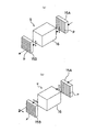
上記光スイッチ9は、レーザビームの照射及び照射停止状態を切換えるものであり、例えば、図2に示すように第1及び第2の偏光素子15A,15Bを、該各偏光素子15A,15Bの偏光軸pが互いに直交するように離して配置し(同図においては、偏光素子15Aの偏光軸pは垂直方向に設定され、偏光素子15Bの偏光軸pは水平方向に設定されている)、該第1及び第2の偏光素子15A,15Bの間に電気光学変調器16を配設した構成を有している。上記電気光学変調器16は、電圧を印加すると偏光(直線偏光)の偏波面を数nsecの高速で回転させるように動作するものである。例えば、印加電圧ゼロのときには、同図(a)において第1の偏光素子15Aにより選択的に透過した例えば垂直方向の偏波面を有する直線偏光は、上記電気光学変調器16をそのまま透過し、第2の偏光素子15Bに達する。この第2の偏光素子15Bは、水平方向の偏波面を有する直線偏光を選択的に透過するように配設されているため、垂直方向の偏波面を有する上記直線偏光は透過できず、この場合レーザビームは照射停止状態になる。一方、同図(b)に示すように、電気光学変調器16に電圧が印加され、該電気光学変調器16に入射する直線偏光の偏波面が90度回転したときには、上記垂直方向の偏波面を有する直線偏光は、電気光学変調器16を出射するときには、水平方向の偏波面を有するものとなり、この直線偏光は、第2の偏光素子15Bを透過する。これにより、レーザビームは照射状態になる。
The
上記光偏向手段10は、レーザビームの走査位置をその走査方向と直交する方向(ガラス基板8の移動方向で図1に示す矢印A方向に一致する)にずらして正しい位置を走査するように調整するものであり、例えば音響光学素子(AO素子)である。 The light deflecting means 10 is adjusted so as to scan the correct position by shifting the scanning position of the laser beam in a direction orthogonal to the scanning direction (coinciding with the direction of arrow A shown in FIG. 1 in the moving direction of the glass substrate 8). For example, an acousto-optic element (AO element) is used.
また、第1のミラー11は、光偏向手段10を通過したレーザビームの進行方向を後述のポリゴンミラー12の設置方向に曲げるためのものであり、平面ミラーである。さらに、ポリゴンミラー12は、レーザビームを往復走査するものであり、例えば正八角形の柱状回転体の側面に八つのミラーを形成している。この場合、上記ミラーの一つで反射されるレーザビームは、ポリゴンミラー12の回転に伴って一次元の往方向に走査され、レーザビームの照射位置が次のミラー面に移った瞬間に復方向に戻って、再びポリゴンミラー12の回転に伴って一次元の往方向への走査を開始することになる。
The
また、fθレンズ13は、レーザビームの走査速度がガラス基板8上で等速となるようにするものであり、焦点位置を上記ポリゴンミラー12のミラー面の位置に略一致させて配置される。そして、第2のミラー14は、fθレンズ13を通過したレーザビームを反射して、ガラス基板8の面に対して略垂直方向に入射させるためのものであり、平面ミラーである。また、上記fθレンズ13の出射側の面近傍部にて往復走査するレーザビームの走査開始側の部分には、走査方向と直交するようにラインセンサー17が設けられており、レーザビームの所定走査位置と実際の走査位置とのずれ量を検出すると共に、レーザビームの走査開始時刻を検出するようになっている。なお、このラインセンサー17は、fθレンズ13側ではなく、レーザビームの走査開始点を検出できればどこに設けてもよく、例えば、後述するガラス基板搬送用のステージ18側に設けてもよい。
Further, the
上記第2のミラー14の下方には、搬送手段4が設けられている。この搬送手段4は、ステージ18上にガラス基板8を載置して、上記レーザビームの走査方向に直交する方向に所定の速度で搬送するものであり、上記ステージ18を移動させる例えば搬送ローラ19と、該搬送ローラ19を回転駆動する例えばモータ等の搬送駆動部20とを備えている。
A conveying
上記搬送手段4の上方にて矢印Aで示す搬送方向の上記レーザビームの走査位置手前側には、撮像手段5が設けられている。この撮像手段5は、ガラス基板8に予め形成された露光の基準となる基準機能パターンとしてのブラックマトリクスのピクセルを撮像するものであり、受光素子が一列状に配列された例えばラインCCDである。ここで、図3に示すように、上記撮像手段5の撮像位置Eと上記レーザビームの走査位置Fとの距離Dは、ブラックマトリクス21のピクセル22の搬送方向配列ピッチPの整数倍(n倍)となるように設定される。これにより、ガラス基板8が搬送されて上記ピクセル22の中心とレーザビームの走査位置とが一致したときにレーザビームが走査を開始するように走査タイミングを合わせることができる。また、上記距離Dは、小さい程よい。これにより、ガラス基板8の移動誤差を少なくすることができ、レーザビームの走査位置を上記ピクセル22に対してより正確に位置決めすることができる。なお、図1には、撮像手段5を三台設置した例を示しているが、レーザビームの走査範囲が一台の撮像手段5の画像処理領域より狭いときには、撮像手段5は一台でよく、上記走査範囲が一台の撮像手段5の画像処理領域より広いときには、それに応じて複数台の撮像手段を設置するとよい。
An
上記搬送手段4の下側には、背面光照射手段6が設けられている。この背面光照射手段6は、上記ピクセル22を照明して撮像手段5による撮像を可能にするものであり、例えば面光源である。
A back light irradiating means 6 is provided below the conveying
上記レーザ光源2、光スイッチ9、光偏向手段10、ポリゴンミラー12、ラインセンサー17、搬送手段4及び撮像手段5に接続して光学系制御手段7が設けられている。この光学系制御手段7は、撮像手段5で取得した二つのピクセル22の画像データを用いて各画像データの論理和を取ることにより、レーザビームの一走査領域に対応するピクセル22画像における欠陥を取除いて無欠陥のピクセル22画像を生成し、該無欠陥のピクセル22画像に露光開始又は終了の基準位置を検出し、該基準位置を基準にしてレーザ光源2におけるレーザビームの照射開始又は照射停止の制御を行うと共に、ラインセンサー17の出力に基づいて光偏向手段10に印加する電圧を制御してレーザビームの出射方向を偏向させ、ポリゴンミラー12の回転速度を制御してレーザビームの走査速度を所定速度に維持し、搬送手段4によるガラス基板8の搬送速度を所定の速度に制御するものである。そして、レーザ光源2を点灯させる光源駆動部23と、レーザビームの照射開始及び照射停止を制御する光スイッチコントローラ24と、光偏向手段10におけるレーザビームの偏向量を制御する光偏向手段駆動部25Aと、ポリゴンミラー12の駆動を制御するポリゴン駆動部25Bと、搬送手段4の搬送速度を制御する搬送コントローラ26と、背面光照射手段6の点灯及び消灯を行う背面光コントローラ27と、撮像手段5で撮像した画像をA/D変換するA/D変換部28と、A/D変換された画像データに基づいてレーザビームの照射開始位置及び照射停止位置を判定する画像処理部29と、画像処理部29で処理して得たレーザビームの照射開始位置(以下、露光開始位置と記載)及び照射停止位置(以下露光終了位置と記載)のデータを記憶すると共に、後述の露光開始位置及び露光終了位置のルックアップテーブル等を記憶する記憶部30と、該記憶部30から読み出した露光開始位置及び露光終了位置のデータに基づいて光スイッチ9をオン/オフする変調データを作成する変調データ作成処理部31と、装置全体が所定の目的の動作をするように適切に制御する制御部32とを備えている。
An optical system control means 7 is provided in connection with the
図4及び図5は、画像処理部29の一構成例を示すブロック図である。図4に示すように、画像処理部29は、例えば三つ並列に接続したリングバッファーメモリ33A,33B,33Cと、該リングバッファーメモリ33A,33B,33C毎にそれぞれ並列に接続した例えば三つのラインバッファーメモリ34A,34B,34Cと、該ラインバッファーメモリ34A,34B,34Cに接続され決まった閾値と比較してグレーレベルのデータを2値化して出力する比較回路35と、上記九つのラインバッファーメモリ34A,34B,34Cの出力データと図1に示す記憶部30から得た露光開始位置を定める第1の基準位置に相当する画像データのルックアップテーブル(露光開始位置用LUT)とを比較して、両データが一致したときに露光開始位置判定結果を出力する露光開始位置判定回路36と、上記九つのラインバッファーメモリ34A,34B,34Cの出力データと、図1に示す記憶部30から得た露光終了位置を定める第2の基準位置に相当する画像データのルックアップテーブル(露光終了位置用LUT)とを比較して、両データが一致したときに露光終了位置判定結果を出力する露光終了位置判定回路37とを備えている。
4 and 5 are block diagrams illustrating an example of the configuration of the
また、図5に示すように、画像処理部29は、上記露光開始位置判定結果を入力して第1の基準位置に相当する画像データの一致回数をカウントする計数回路38Aと、該計数回路38Aの出力と図1に示す記憶部30から得た露光開始ピクセル番号とを比較して両数値が一致したときに露光開始信号を図1に示す変調データ作成処理部31に出力する比較回路39Aと、上記露光終了位置判定結果を入力して第2の基準位置に相当する画像データの一致回数をカウントする計数回路38Bと、該計数回路38Bの出力と図1に示す記憶部30から得た露光終了ピクセル番号とを比較して両数値が一致したときに露光終了信号を図1に示す変調データ作成処理部31に出力する比較回路39Bと、上記計数回路38Aの出力に基づいて先頭ピクセルの数をカウントする先頭ピクセル計数回路40と、該先頭ピクセル計数回路40の出力と図1に示す記憶部30から得た露光ピクセル列番号とを比較して両数値が一致したときに露光ピクセル列指定信号を図1に示す変調データ作成処理部31に出力する比較回路41とを備えている。なお、上記計数回路38A,37Bは、撮像手段5による読取動作が開始されるとその読取開始信号によりリセットされる。また、先頭ピクセル計数回路40は、予め指定した所定の露光パターンの形成が終了すると露光パターン終了信号によりリセットされる。
As shown in FIG. 5, the
次に、このように構成された露光装置1の動作及びパターン形成方法について説明する。
先ず、露光装置1に電源が投入されると、光学系制御手段7が駆動する。これにより、レーザ光源2が起動してレーザビームが発射される。同時に、ポリゴンミラー12が回転を開始し、レーザビームの走査が可能になる。ただし、このときはまだ、光スイッチ9はオフされているためレーザビームは照射されない。
Next, the operation of the
First, when the
次に、搬送手段4のステージ18上にガラス基板8が載置される。なお、搬送手段4は、一定速度でガラス基板8を搬送するため、図6に示すようにレーザビームの走査軌跡(矢印B)は、ステージ18の移動方向(矢印A)に対して相対的に斜めとなる。従って、ガラス基板8を上記移動方向(矢印A)に平行に設置している場合には、同図(a)に示すように露光位置がブラックマトリクス21の走査開始ピクセル22aと走査終了ピクセル22bとでずれる場合が生ずる。この場合には、同図(b)に示すように、ガラス基板8を搬送方向(矢印A方向)に対して傾けて設置して上記ピクセル22の配列方向とレーザビームの走査軌跡(矢印B)とが一致するようにするとよい。ただし、現実には、レーザビームの走査速度の方がガラス基板8の搬送速度よりもはるかに速いため上記ずれ量は少ない。従って、ガラス基板8は移動方向に対して平行に設置し、上記ずれ量を撮像手段5で撮像したデータに基づいて計測して、露光光学系3の光偏向手段10を制御してずれ量を補正してもよい。なお、以下の説明においては、上記ずれ量は無視できるものとして説明する。
Next, the
次に、搬送駆動部20を駆動してステージ18を図1の矢印A方向に移動する。このとき、搬送駆動部20は、光学系制御手段7の搬送コントローラ26により一定速度となるように制御される。
Next, the
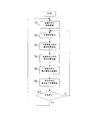
次に、ガラス基板8に形成されたブラックマトリクス21が撮像手段5の撮像位置に達すると、撮像手段5は撮像を開始し、撮像したブラックマトリクス21の画像データに基づいて露光開始位置及び露光終了位置の検出を行う。以下、パターン形成方法を図7に示すフローチャートを参照して説明する。
Next, when the
先ず、ステップS1において、撮像手段5でブラックマトリクス21のピクセル22の画像が取得される。この取得した画像データは、図4に示す画像処理部29の三つのリングバッファーメモリ33A,33B,33Cに取り込まれて処理される。そして、最新の三つのデータが各リングバッファーメモリ33A,33B,33Cから出力される。この場合、例えばリングバッファーメモリ33Aから二つ前のデータが出力され、リングバッファーメモリ33Bから一つ前のデータが出力され、リングバッファーメモリ33Cから最新のデータが出力される。さらに、これらの各データはそれぞれ三つのラインバッファーメモリ34A,34B,34Cにより、例えば3×3のCCD画素の画像を同一のクロック(時間軸)に配置する。その結果は、例えば図8(a)に示すような画像として得られる。この画像を数値化すると、同図(b)のように3×3の数値に対応することになる。これらの数値化された画像は、同一クロック上に並んでいるので、比較回路35で閾値と比較されて2値化される。例えば、閾値を“45”とすれば、同図(a)の画像は、同図(c)のように2値化されることになる。
First, in step S <b> 1, the image of the
次に、ステップS2において、露光開始及び露光終了の基準位置が検出される。具体的には、基準位置検出は、露光開始位置判定回路36において、上記2値化データを図1に示す記憶部30から得た露光開始位置用LUTのデータと比較して行う。
Next, in step S2, a reference position for exposure start and exposure end is detected. Specifically, the reference position is detected by comparing the binarized data with the exposure start position LUT data obtained from the
例えば、露光開始位置を指定する第1の基準位置が、図9(a)に示すようにブラックマトリクス21のピクセル22の左上端隅部に設定されている場合には、上記露光開始用LUTは、同図(b)に示すものになり、このときの露光開始用LUTのデータは、“000011011”となる。従って、上記2値化データは、上記露光開始用LUTのデータ“000011011”と比較され、両データが一致したときに、撮像手段5で取得した画像データが第1の基準位置であると判定され、露光開始位置判定回路36から開始位置判定結果を出力する。なお、図10に示すようにピクセル22が六つ並んでいるときには、各ピクセル22の左上端隅部が第1の基準位置に該当することになる。
For example, when the first reference position for designating the exposure start position is set at the upper left corner of the
なお、図11に示すように、ステージ18やガラス基板8上に異物や傷が存在して、撮像手段5によりその異物等による欠陥42の画像がピクセル22内に取得されると、該欠陥42を基準位置と誤認する虞がある。そこで、本第1の実施形態においては、撮像手段5により取得したピクセル列L1の画像データを記憶部20に記憶する。そして、次のピクセル列L2の画像データを取得すると、記憶部20からピクセル列L1の画像データを読出し、同図(a)に示すように画像処理部29においてガラス基板8の移動方向(矢印A方向)の前後にて互いに同位置にあるピクセル22の画像データの論理和を取る。このとき、二つのピクセル22の同位置に欠陥42が同時に存在することはまれであり、したがって、各ピクセル22の画像データの論理和を取ることにより欠陥42を画像データから取除くことができる。これにより、無欠陥のピクセル列の画像データを用いて上述のような基準位置の検出を行う。
As shown in FIG. 11, when a foreign matter or a flaw exists on the
また、最後列のピクセル列に対しては、新たなピクセル列の画像取得ができないために、上述の方法により欠陥42を取除くことはできない。この場合には、隣同士のピクセル22の画像データの論理和を取ることにより、欠陥42の画像を取除く。具体的には、図11(b)に示すように取得した最後列のピクセル列Ln画像と、該ピクセル列Ln画像を列方向に1ピッチずらした画像とについてガラス基板8の移動方向(矢印A方向)の前後にて互いに同位置にあるピクセル22の画像データの論理和を取る。この場合、隣同士のピクセル22の同位置に欠陥42が同時に存在することはまれであり、したがって、各ピクセル22の画像データの論理和を取ることにより、最後列のピクセル列Lnに対しても欠陥42を画像から取除くことができる。これにより、無欠陥のピクセル列を生成することができる。
Further, since the image of a new pixel row cannot be acquired for the last pixel row, the
次に、上記判定結果に基づいて、図5に示す計数回路38Aにおいて上記一致回数がカウントされる。そして、そのカウント数は、図1に示す記憶部30から得た露光開始ピクセル番号と比較回路39Aにおいて比較され、両数値が一致したとき露光開始信号を図1に示す変調データ作成処理部31に出力する。この場合、図10に示すように、例えば、レーザビームの走査方向にて1番目のピクセル221及び4番目のピクセル224の左上端隅部を第1の基準位置と定めると、該第1の基準位置に対応する撮像手段5のラインCCDにおけるエレメント番地、例えば“1000”,“4000”が光スイッチコントローラ24に記憶される。
Next, the number of coincidences is counted in the
一方、上記2値化データは、露光終了位置判定回路37において、図1に示す記憶部30から得た露光終了位置用LUTのデータと比較される。例えば、露光終了位置を指定する第2の基準位置が、図12(a)に示すようにブラックマトリクス21のピクセル22の右上端隅部に設定されている場合には、上記露光終了位置用LUTは、同図(b)に示すものになり、このときの露光終了位置用LUTのデータは、“110110000”となる。従って、上記2値化データは、上記露光終了位置用LUTのデータ“110110000”と比較され、両データが一致したときに、撮像手段5で取得した画像データが露光終了の基準位置であると判定され、露光終了位置判定回路37から終了位置判定結果を出力する。なお、前述と同様に、図10に示すように例えばピクセル22が六つ並んでいるときには、各ピクセル22の右上端隅部が第2の基準位置に該当することになる。
On the other hand, the binarized data is compared with the exposure end position LUT data obtained from the
上記判定結果に基づいて、図5に示す計数回路38Bにおいて上記一致回数がカウントされる。そして、そのカウント数は、図1に示す記憶部30から得た露光終了ピクセル番号と比較回路39Bにおいて比較され、両数値が一致したとき露光終了信号を図1に示す変調データ作成処理部31に出力する。この場合、図10に示すように、例えば、レーザビームの走査方向にて1番目のピクセル221及び第4番目のピクセル224の右上端隅部を第2の基準位置と定めると、該第2の基準位置に対応する撮像手段5のラインCCDにおけるエレメント番地、例えば“1900”,“4900”が光スイッチコントローラ24に記憶される。そして、上述のようにして露光開始位置及び露光終了位置の基準位置が検出されると、ステップS3に進む。
Based on the determination result, the number of matches is counted in the
ステップS3では、ガラス基板8の移動方向における露光位置が検出される。ここで、図3に示すように、レーザビームの走査位置Fと撮像手段5の撮像位置E間の距離Dは、上記ピクセル22の移動方向への配列ピッチPの整数倍(n倍)に設定されているため、レーザビームの走査周期をカウントすることによって上記露光位置を割り出すことができる。例えば、図13に示すように、レーザビームの走査位置と撮像手段5の撮像位置との間の距離Dがピクセル22の配列ピッチPの例えば3倍に設定されている場合に、ステップS2においてピクセル22の端部に第1及び第2の基準位置を検出した後(同図(a)参照)、ガラス基板8が移動してピクセル列中心線が撮像手段5の撮像位置に達したとき(同図(b)参照)、レーザビームの走査開始タイミングと一致する。ここで、レーザビームが周期Tで走査している場合、ガラス基板8の搬送速度は、レーザビームの周期Tに同期してピクセル22の1ピッチ分だけ移動するように制御される。したがって、次の1T間にピクセル22は同図(c)に示す位置に移動する。さらに、2T後には、ピクセル22は同図(d)に示す位置まで移動する。そして、3T後には、同図(e)に示すように、ピクセル22の列中心線がレーザビームの走査位置に達することになる。こうして、露光位置が検出される。
In step S3, the exposure position in the moving direction of the
次に、ステップS4において、レーザビームを走査しながら、上記露光位置の調整が行われる。具体的には、図14に示すように、露光位置の調整は、fθレンズ13に設けたラインセンサー17で検出した現在のレーザビームの走査位置(エレメント番地)と予め定めた基準エレメント番地とを比較してそのずれ量を検出し、光偏向手段10を制御してレーザビームの走査位置を基準エレメント番地(基準走査位置)に一致させるようにして行う。
Next, in step S4, the exposure position is adjusted while scanning the laser beam. Specifically, as shown in FIG. 14, the exposure position is adjusted by changing the current laser beam scanning position (element address) detected by the
次に、ステップS5において、露光が開始される。露光開始は、光スイッチ9のオンタイミングを光スイッチコントローラ24で制御して行う。この場合、先ず、光スイッチ9をオン状態にしてレーザビームを走査し、上記ラインセンサー17によってレーザビームの走査開始時刻が検出されると直ぐに光スイッチ9をオフとする。このとき、変調データ作成処理部31から、例えば図10の露光開始位置に対応する撮像手段5のエレメント番地“1000”が読み出されレーザビームの走査開始時刻から露光開始位置までの時間t1が制御部32で演算される。この場合、レーザビームの走査開始時刻から撮像手段5のエレメント番地“1”までの走査時間t0を予め計測しておき、またレーザビームの走査速度を撮像手段5のラインCCDのクロックCLKに同期させておけば、エレメント番地“1000”までのクロック数をカウントすることにより、走査開始時刻t1は、t1=t0+1000CLKとして容易に求めることができる。これにより、レーザビームの走査開始時刻からt1後に光スイッチ9をオンして露光を開始する。
Next, in step S5, exposure is started. The exposure is started by controlling the ON timing of the
次に、ステップS6において、露光終了位置が検出される。露光終了位置は、上述と同様にして、例えばエレメント番地“1900”における露光終了時刻t2は、t2=t0+1900CLKとして求まる。これにより、レーザビームの走査開始時刻からt2後に光スイッチ9をオフして露光を終了する。
Next, in step S6, the exposure end position is detected. The exposure end position is obtained in the same manner as described above, for example, the exposure end time t 2 at the element address “1900” is t 2 = t 0 +1900 CLK. As a result, the
次に、ステップS7においては、レーザビームの一走査が終了したか否かを判定する。ここで、“NO”判定となると、ステップS2に戻って上述の動作を繰返す。そして、ステップS2において、図10に示すように、例えば第2の露光開始位置“4000”及び第2の露光終了位置“4900”が検出されると、ステップS4を経てステップS5に進んで、上述と同様にしてエレメント番地“4000”から露光が開始され、エレメント番地“4900”で露光が終了する。 Next, in step S7, it is determined whether one scanning of the laser beam is completed. If "NO" determination is made here, the process returns to step S2 and the above-described operation is repeated. Then, in step S2, as shown in FIG. 10, for example, when the second exposure start position “4000” and the second exposure end position “4900” are detected, the process proceeds to step S5 through step S4, and the above-mentioned. In the same manner as described above, the exposure starts from the element address “4000”, and the exposure ends at the element address “4900”.
また、ステップS7において、“YES”判定となるとステップS1に戻り、新たな露光位置を検出する動作に移る。そして、上述の動作を繰り返し実行することにより、所望の領域に対して露光パターンの形成を行う。 If “YES” determination is made in step S7, the process returns to step S1 to move to an operation for detecting a new exposure position. Then, by repeatedly executing the above operation, an exposure pattern is formed on a desired area.
このように、上記実施形態によれば、撮像手段5で取得して記憶部20に記憶した第1のピクセル列の画像データを読み出し、新たに取得した次のピクセル列の画像データとの論理和を取るようにしたことにより、ステージ18やガラス基板8に付着した異物や傷等の欠陥42による本来のピクセル列の画像と異なる画像を取除いて、無欠陥のピクセル列の画像データを生成することができる。したがって、上記欠陥42を基準位置と誤認して露光することを防止することができ、所定の機能パターンの露光精度を向上することができる。
As described above, according to the above-described embodiment, the image data of the first pixel column acquired by the
また、上記無欠陥のピクセル列の画像データを用いてピクセル22に予め定めた基準位置を検出し、該基準位置に基づいて露光パターンを形成するようにしているので、ピクセル22に対する機能パターンの重ね合せ精度が向上する。したがって、複数の露光装置1を使用して積層パターンを形成する工程に適用した場合にも高い重ね合わせ精度を確保することができる。これにより、各露光装置間の機械精度を揃える必要が無く、露光装置1のコストアップを抑制することができる。
In addition, since a reference position predetermined for the
そして、上記ピクセル22に予め定めた基準位置を撮像手段5で読み取り、該基準位置を基準にして露光及び露光停止をするようにしているので事前に上記ピクセル22と露光パターンとのアライメントを取る必要が無く、露光作業が容易になる。
Then, the reference position predetermined for the
図15は、第2の発明による露光装置の実施形態を示す概念図である。なお、ここでは、図1に示す露光装置と異なる部分について説明する。この第2の発明は、レーザビームの走査範囲よりも狭い画像処理領域を有する撮像手段5を一台だけ備えたものである。 FIG. 15 is a conceptual view showing an embodiment of an exposure apparatus according to the second invention. Here, parts different from the exposure apparatus shown in FIG. 1 will be described. The second invention comprises only one image pickup means 5 having an image processing area narrower than the scanning range of the laser beam.
この場合、ブラックマトリクス21のピクセル22に設定された基準位置の検出は、図16に示すように一台の撮像手段5により例えばピクセル列L1の画像データを取得し、該取得した画像データと図5に示す露光開始位置用LUT及び露光終了位置用LUTと比較して行う。これにより、例えば1番目のピクセル221の左上端隅部に露光開始位置が、また4番目のピクセル224の右上端隅部に露光終了位置が設定されると、これに対応した撮像手段5のラインCCDのエレメント番地、例えば“1000”及び“4900”を記憶部20に記憶する。
In this case, for the detection of the reference position set for the
一方、ピクセル22が列方向に所定のピッチで配列されている場合には、撮像手段5で取得したピクセル列画像を、該撮像手段5の画像処理領域43Aに後続する領域に複写して撮像手段5で取得できないピクセル列画像を補完し、該補完されたピクセル列画像に基づいて露光を行う。即ち、列方向のピクセル22の配列ピッチがW(例えば、1000CLK)であるとき、撮像手段5の画像処理領域43Aに続くピクセル列画像は、例えば図16(a)に示すように、露光開始位置“1000”から4W(=4000CLK)後から始まることになる。したがって、記憶部20から読み出した露光開始位置“1000”と露光終了位置“4900”との間の“3900CLK”時間だけ露光を行った後、同じ露光制御(例えば、露光時間“3900CLK”)を露光開始位置“1000”から4W後の領域(複写されたピクセル列画像領域43B)に対して適用すれば、同図(b)に示すように撮像手段5の画像処理領域43Aに続くピクセル列に対しても同じ露光パターン44を形成することができる。さらに、同様の操作を繰返し実行すれば、ピクセル列の全領域に対して露光を行うことができる。
On the other hand, when the
このように第2の発明によれば、撮像手段5で取得したピクセル列の画像を、それに続く画像の欠落した領域に複写してピクセル列画像を生成し、該生成されたピクセル列画像に基づいて露光するようにしたことにより、上記撮像手段5で取得できない領域のピクセル列に対しても所定の機能パターンを高精度に露光することができる。
As described above, according to the second aspect of the present invention, the pixel column image acquired by the
また、ピクセル列の全画像を取得する必要がないため撮像手段5の設置台数を減らすことができ、露光装置のコストを低減することができる。この場合、画像処理領域43Aは狭くてもよいので高解像度の撮像手段5を適用することができ、基準位置の検出精度が向上する。したがって、露光パターンの露光精度をより向上することができる。
In addition, since it is not necessary to acquire all the images of the pixel row, the number of installed image pickup means 5 can be reduced, and the cost of the exposure apparatus can be reduced. In this case, since the
なお、図15においては、撮像手段5を搬送手段4の上方に配設した例を示しているが、搬送手段4の下方に配設してもよい。この場合、ステージ18に形成されたガラス基板8を吸着する吸着溝や取り付けボルト等の存在により、ガラス基板8に予め形成されたブラックマトリクス21のピクセル列の撮像手段による取得画像に欠落が生じることがある。このとき、上述と同様にして、撮像手段5で取得できないピクセル列画像を補完するようにすれば、上記吸着溝や取り付けボルト等の陰に隠れたピクセル列に対しても所定の機能パターンを高精度に露光することができる。
Although FIG. 15 shows an example in which the
また、上記第1及び第2の実施形態においては、照明手段を背面照明としたが落射照明としてもよい。
そして、本発明の露光装置は、液晶ディスプレイのカラーフィルター等の大型基板に適用するものに限定されず、半導体等の露光装置にも適用することができる。
Moreover, in the said 1st and 2nd embodiment, although the illumination means was made into back illumination, it is good also as epi-illumination.
And the exposure apparatus of this invention is not limited to what is applied to large sized substrates, such as a color filter of a liquid crystal display, It can apply also to exposure apparatuses, such as a semiconductor.
1…露光装置
5…撮像手段
7…光学系制御手段
8…ガラス基板(被露光体)
21…ブラックマトリクス
22…ピクセル(基準機能パターン)
42…欠陥
43…画像処理領域(所定領域)
DESCRIPTION OF
21 ...
42 ... Defect 43 ... Image processing area (predetermined area)
Claims (4)
前記被露光体に予め形成された露光位置の基準となる基準機能パターンを撮像する撮像手段と、
前記撮像手段で取得した二つの前記基準機能パターンの画像データを用いて各画像データの論理和を取ることにより、前記光ビームの一走査領域に対応する基準機能パターン画像における欠陥を取除いて無欠陥の基準機能パターン画像を生成し、該無欠陥の基準機能パターン画像に露光開始又は終了の基準位置を検出し、該基準位置を基準にして前記光ビームの照射開始又は照射停止の制御をする光学系制御手段と、
を備えたことを特徴とする露光装置。 An exposure apparatus that relatively scans a light beam emitted from an exposure optical system in a direction orthogonal to a moving direction of an object to be exposed, and exposes a functional pattern on the object to be exposed at a predetermined pitch,
An imaging means for imaging a reference function pattern serving as a reference of an exposure position formed in advance on the object to be exposed;
By taking the logical sum of the image data using the image data of the two reference function patterns acquired by the imaging means, the defects in the reference function pattern image corresponding to one scanning area of the light beam are removed. A defect reference function pattern image is generated, an exposure start or end reference position is detected in the defect-free reference function pattern image, and the light beam irradiation start or irradiation stop is controlled based on the reference position. Optical system control means;
An exposure apparatus comprising:
前記被露光体に予め形成された露光位置の基準となる基準機能パターンを撮像する撮像手段と、
前記撮像手段で取得した所定領域の前記基準機能パターンの画像データを、前記所定領域に後続する領域に複写して前記撮像手段で取得できない基準機能パターンの画像を補完し、該補完された基準機能パターン画像に露光開始又は終了の基準位置を検出し、該基準位置を基準にして前記光ビームの照射開始又は照射停止の制御をする光学系制御手段と、
を備えたことを特徴とする露光装置。 An exposure apparatus that relatively scans a light beam emitted from an exposure optical system in a direction orthogonal to a moving direction of an object to be exposed, and exposes a functional pattern on the object to be exposed at a predetermined pitch,
An imaging means for imaging a reference function pattern serving as a reference of an exposure position formed in advance on the object to be exposed;
The image data of the reference function pattern of the predetermined area acquired by the imaging unit is copied to an area subsequent to the predetermined area to complement the image of the reference function pattern that cannot be acquired by the imaging unit, and the supplemented reference function An optical system control unit that detects a reference position of exposure start or end in the pattern image and controls the start or stop of irradiation of the light beam with reference to the reference position;
An exposure apparatus comprising:
Priority Applications (6)
| Application Number | Priority Date | Filing Date | Title |
|---|---|---|---|
| JP2004134443A JP4253708B2 (en) | 2004-04-28 | 2004-04-28 | Exposure equipment |
| TW094113749A TWI347450B (en) | 2004-04-28 | 2005-04-28 | Exposing apparatus |
| PCT/JP2005/008117 WO2005106596A1 (en) | 2004-04-28 | 2005-04-28 | Exposure apparatus |
| CN2005800133483A CN1947069B (en) | 2004-04-28 | 2005-04-28 | Exposure apparatus |
| CN2010102005923A CN101846889B (en) | 2004-04-28 | 2005-04-28 | Exposure apparatus |
| KR1020067022508A KR101103155B1 (en) | 2004-04-28 | 2005-04-28 | Exposure apparatus |
Applications Claiming Priority (1)
| Application Number | Priority Date | Filing Date | Title |
|---|---|---|---|
| JP2004134443A JP4253708B2 (en) | 2004-04-28 | 2004-04-28 | Exposure equipment |
Publications (3)
| Publication Number | Publication Date |
|---|---|
| JP2005317800A JP2005317800A (en) | 2005-11-10 |
| JP2005317800A5 JP2005317800A5 (en) | 2007-05-24 |
| JP4253708B2 true JP4253708B2 (en) | 2009-04-15 |
Family
ID=35241832
Family Applications (1)
| Application Number | Title | Priority Date | Filing Date |
|---|---|---|---|
| JP2004134443A Expired - Fee Related JP4253708B2 (en) | 2004-04-28 | 2004-04-28 | Exposure equipment |
Country Status (5)
| Country | Link |
|---|---|
| JP (1) | JP4253708B2 (en) |
| KR (1) | KR101103155B1 (en) |
| CN (2) | CN1947069B (en) |
| TW (1) | TWI347450B (en) |
| WO (1) | WO2005106596A1 (en) |
Families Citing this family (3)
| Publication number | Priority date | Publication date | Assignee | Title |
|---|---|---|---|---|
| KR101002156B1 (en) | 2008-03-31 | 2010-12-17 | 다이니폰 스크린 세이조우 가부시키가이샤 | Pattern drawing apparatus and pattern drawing method |
| KR102065012B1 (en) * | 2016-07-26 | 2020-01-10 | 에이피시스템 주식회사 | Laser Processing Apparatus And Method |
| JP6917727B2 (en) * | 2017-02-15 | 2021-08-11 | 株式会社ディスコ | Laser processing equipment |
Family Cites Families (5)
| Publication number | Priority date | Publication date | Assignee | Title |
|---|---|---|---|---|
| JPS6010730A (en) * | 1983-06-30 | 1985-01-19 | Toshiba Corp | Positioning method of semiconductor wafer |
| JP2551049B2 (en) * | 1987-11-10 | 1996-11-06 | 株式会社ニコン | Alignment device |
| JP2797506B2 (en) * | 1989-08-31 | 1998-09-17 | 凸版印刷株式会社 | Exposure equipment |
| JPH03201454A (en) * | 1989-12-28 | 1991-09-03 | Fujitsu Ltd | Aligning method for semiconductor device |
| JP2004012903A (en) * | 2002-06-07 | 2004-01-15 | Fuji Photo Film Co Ltd | Aligner |
-
2004
- 2004-04-28 JP JP2004134443A patent/JP4253708B2/en not_active Expired - Fee Related
-
2005
- 2005-04-28 CN CN2005800133483A patent/CN1947069B/en not_active Expired - Fee Related
- 2005-04-28 WO PCT/JP2005/008117 patent/WO2005106596A1/en active Application Filing
- 2005-04-28 CN CN2010102005923A patent/CN101846889B/en not_active Expired - Fee Related
- 2005-04-28 TW TW094113749A patent/TWI347450B/en not_active IP Right Cessation
- 2005-04-28 KR KR1020067022508A patent/KR101103155B1/en active IP Right Grant
Also Published As
| Publication number | Publication date |
|---|---|
| TW200535453A (en) | 2005-11-01 |
| CN1947069B (en) | 2010-09-29 |
| CN101846889B (en) | 2012-05-09 |
| TWI347450B (en) | 2011-08-21 |
| KR20070001252A (en) | 2007-01-03 |
| WO2005106596A1 (en) | 2005-11-10 |
| KR101103155B1 (en) | 2012-01-04 |
| CN101846889A (en) | 2010-09-29 |
| CN1947069A (en) | 2007-04-11 |
| JP2005317800A (en) | 2005-11-10 |
Similar Documents
| Publication | Publication Date | Title |
|---|---|---|
| TWI394007B (en) | Exposing apparatus | |
| US7812920B2 (en) | Production method of substrate for liquid crystal display using image-capturing and reference position detection at corner of pixel present in TFT substrate | |
| JP2006017895A (en) | Aligner | |
| KR101094468B1 (en) | Exposure pattern forming method | |
| JP4253708B2 (en) | Exposure equipment | |
| KR101098729B1 (en) | Apparatus for and method of exposure patterns | |
| JPH0389511A (en) | Exposure device | |
| JP4195413B2 (en) | Exposure apparatus and pattern forming method | |
| JP4235584B2 (en) | Exposure apparatus and pattern forming method | |
| JP2003237031A (en) | Alignment device for screen printing | |
| JP4613098B2 (en) | Exposure equipment | |
| JP2009058698A (en) | Exposure apparatus | |
| JP4338628B2 (en) | Exposure equipment | |
| JP2003315014A (en) | Inspection method and inspection device | |
| TWI386762B (en) | Apparatus for and method of exposure patterns | |
| JP4650813B2 (en) | Reticle defect inspection apparatus and reticle defect inspection method | |
| JP4951036B2 (en) | Exposure equipment | |
| JPH10162145A (en) | Arithmetic unit for calculating correction data of center coordinate data of registered pattern in pattern matching method, and laser plotting device using it | |
| JP2024046030A (en) | Template generating device, drawing system, template generating method and program | |
| JP2009058382A (en) | Image acquisition method by multiple scan, image acquisition device, and sample inspection device | |
| JP2003153063A (en) | Imaging apparatus |
Legal Events
| Date | Code | Title | Description |
|---|---|---|---|
| A521 | Written amendment |
Free format text: JAPANESE INTERMEDIATE CODE: A523 Effective date: 20070330 |
|
| A621 | Written request for application examination |
Free format text: JAPANESE INTERMEDIATE CODE: A621 Effective date: 20070330 |
|
| A131 | Notification of reasons for refusal |
Free format text: JAPANESE INTERMEDIATE CODE: A131 Effective date: 20080916 |
|
| A521 | Written amendment |
Free format text: JAPANESE INTERMEDIATE CODE: A523 Effective date: 20081113 |
|
| TRDD | Decision of grant or rejection written | ||
| A01 | Written decision to grant a patent or to grant a registration (utility model) |
Free format text: JAPANESE INTERMEDIATE CODE: A01 Effective date: 20081209 |
|
| A01 | Written decision to grant a patent or to grant a registration (utility model) |
Free format text: JAPANESE INTERMEDIATE CODE: A01 |
|
| A711 | Notification of change in applicant |
Free format text: JAPANESE INTERMEDIATE CODE: A711 Effective date: 20081212 |
|
| RD03 | Notification of appointment of power of attorney |
Free format text: JAPANESE INTERMEDIATE CODE: A7423 Effective date: 20081212 |
|
| A61 | First payment of annual fees (during grant procedure) |
Free format text: JAPANESE INTERMEDIATE CODE: A61 Effective date: 20081212 |
|
| FPAY | Renewal fee payment (event date is renewal date of database) |
Free format text: PAYMENT UNTIL: 20120206 Year of fee payment: 3 |
|
| R150 | Certificate of patent or registration of utility model |
Ref document number: 4253708 Country of ref document: JP Free format text: JAPANESE INTERMEDIATE CODE: R150 Free format text: JAPANESE INTERMEDIATE CODE: R150 |
|
| FPAY | Renewal fee payment (event date is renewal date of database) |
Free format text: PAYMENT UNTIL: 20120206 Year of fee payment: 3 |
|
| FPAY | Renewal fee payment (event date is renewal date of database) |
Free format text: PAYMENT UNTIL: 20150206 Year of fee payment: 6 |
|
| R250 | Receipt of annual fees |
Free format text: JAPANESE INTERMEDIATE CODE: R250 |
|
| R250 | Receipt of annual fees |
Free format text: JAPANESE INTERMEDIATE CODE: R250 |
|
| R250 | Receipt of annual fees |
Free format text: JAPANESE INTERMEDIATE CODE: R250 |
|
| R250 | Receipt of annual fees |
Free format text: JAPANESE INTERMEDIATE CODE: R250 |
|
| LAPS | Cancellation because of no payment of annual fees |