JP4251177B2 - Vehicle door structure - Google Patents
Vehicle door structure Download PDFInfo
- Publication number
- JP4251177B2 JP4251177B2 JP2005373589A JP2005373589A JP4251177B2 JP 4251177 B2 JP4251177 B2 JP 4251177B2 JP 2005373589 A JP2005373589 A JP 2005373589A JP 2005373589 A JP2005373589 A JP 2005373589A JP 4251177 B2 JP4251177 B2 JP 4251177B2
- Authority
- JP
- Japan
- Prior art keywords
- door
- vehicle
- bracket
- reinforcement
- pipe member
- Prior art date
- Legal status (The legal status is an assumption and is not a legal conclusion. Google has not performed a legal analysis and makes no representation as to the accuracy of the status listed.)
- Expired - Lifetime
Links
Images


Description
この発明は、センターピラーの無い車体、典型的には、フロントドアとリアドアとを観音開きにした車体の側部に加わる衝撃に対する車体側部の強度を確保するようにした車両のドア構造に関する。 The present invention relates to a vehicle door structure in which the strength of a side portion of a vehicle body with respect to an impact applied to a side portion of a vehicle body having a center pillar without a center pillar, typically a front door and a rear door having a double door opening is ensured.
典型的にはフロントドアとリアドアとが観音開きする車両のように、フロントドアに対応する開口部とリアドアに対応する開口部とが、これらフロントドアとリアドアとを開放したときに一つの開口部を形成する車両にあっては、センターピラーを配置させることができないため、車体開口部の剛性、ドア本体の強度・剛性の向上が要求される。そして、ドア本体の強度・剛性向上の対策としては、一般的に、特許文献1に見られるように、車体前後方向に延びるインパクトバーをドア内部に配置することにより、車体側部に加わる衝撃に対する車体側部の強度を確保することが既に提案されている。
Typically, like a vehicle in which the front door and the rear door are double-opened, the opening corresponding to the front door and the opening corresponding to the rear door form one opening when the front door and the rear door are opened. In the vehicle to be formed, since the center pillar cannot be disposed, it is required to improve the rigidity of the vehicle body opening and the strength and rigidity of the door body. As a measure for improving the strength and rigidity of the door body, generally, as seen in
また、センターピラーレスの車両では、シートベルトリトラクタのような機能部品の取付剛性を確保するのが難しいため、特許文献2に見られるように、リアドアの前端の上下にアッパドアロックとロアドアロックとを設けると共に、アッパドアロックをリアドアに取り付けるためのアッパドアロック取付用ブラケットにフロントシート用のシートベルトのショルダアンカを取り付け、また、ロアドアロックをリアドアに取り付けるためのロアドアロック取付用ブラケットにフロントシート用のシートベルトのラップアウタアンカとシートベルトリトラクタとを取り付けることが既に提案されている。
本発明の目的は、センターピラーの無い車体の車体側部の強度を確保しつつ、シートベルトリトラクタのような機能部品の取り付けのための補強部材を増設する必要のない車両のドア構造を提供することにある。 SUMMARY OF THE INVENTION An object of the present invention is to provide a vehicle door structure that ensures the strength of a vehicle body side portion of a vehicle body without a center pillar and does not require additional reinforcement members for attaching functional parts such as a seat belt retractor. There is.
かかる技術的課題は、本発明によれば、
アウターパネルとインナパネルを備えたフロントドアに対応する前席乗員用開口と、アウターパネルとインナパネルを備えたリアドアに対応する後席乗員用開口とが、これらフロントドアとリアドアを開いたときに、仕切の無い一つの開口部を形成する車両のドア構造であって、
前記フロントドアの後端部又は前記リアドアの前端部のアウタパネルとインナパネルとで囲まれた内部空間にパイプ部材及び縦レインフォースメントが配設され、
前記パイプ部材はベルトラインを挟んで上下に延び、
前記縦レインフォースメントは、前記パイプ部材に隣接して且つ該パイプ部材に連結して配置され、また、上下方向に延びてその上端及び下端が側面視で車体側部材とオーバーラップし、
前記車体側部材には、該車体側部材と縦レインフォースメントの上端部とがオーバーラップする部位にストライカが配設され、
前記縦レインフォースメントにおける前記パイプ部材よりも上方位置に、前記ストライカと係合してドアを閉状態に保持するためのドアロック部材が設けられていることを特徴とする車両のドア構造を提供することにより達成される。
According to the present invention, such a technical problem is
When the front door and the rear door are opened, the front seat occupant opening corresponding to the front door having the outer panel and the inner panel and the rear seat occupant opening corresponding to the rear door having the outer panel and the inner panel are opened. , A vehicle door structure that forms one opening without a partition,
The pipe member and the longitudinal reinforcement is arranged in the internal space surrounded by the rear end or the outer panel and the inner panel of the front end portion of the rear door of the front door,
The pipe member extends up and down across the belt line,
The vertical reinforcement is disposed adjacent to the pipe member and connected to the pipe member. The vertical reinforcement extends in the vertical direction, and the upper end and the lower end overlap the vehicle body side member in a side view.
The vehicle body side member is provided with a striker at a portion where the vehicle body side member and the upper end portion of the vertical reinforcement overlap.
Provided is a door structure for a vehicle, wherein a door lock member is provided at a position above the pipe member in the vertical reinforcement to engage with the striker and hold the door in a closed state. Is achieved.
好ましい実施の形態では、前記フロントドアの後端部及び/又は前記リアドアの前端部に設けた縦レインフォースメント及びこれに隣接配置され且つ車室側から車外側に向けて略半周抱きかかられた状態のパイプ部材とで車体側部の強度を確保できる。 In a preferred embodiment, the longitudinal reinforcement provided at the rear end portion of the front door and / or the front end portion of the rear door, and adjacent to the longitudinal reinforcement, are hugged approximately half a circumference from the passenger compartment side toward the vehicle exterior side. The strength of the side portion of the vehicle body can be secured with the pipe member in the state of being damaged .
本発明の好ましい実施の形態では、上記機能部品はドアロック部材であってもよい。好ましくは、車室側に膨出し且つ車外側に開放した断面略半円形の縦溝を備えた第1ブラケットを介して前記パイプ部材が車室側から車外側に向けて略半周抱きかかえた状態で前記レインフォースメントに隣接配置され、前記ドアロック部材が、平面視したときに前記第1ブラケットと前記縦レインフォースメントとの間に形成される空間に配設され、該ドアロック部材は、前記第1ブラケットと前記縦レインフォースメントとに連結され且つ前記第1ブラケットと前記縦レインフォースメントとの間に亘って延びる第2ブラケットを介して前記縦レインフォースメントに取り付けられるのがよい。 In a preferred embodiment of the present invention, the functional component may be a door lock member. Preferably, the pipe member is held approximately half a circumference from the passenger compartment side toward the outer side of the vehicle through a first bracket having a longitudinal groove having a substantially semicircular cross section opened to the outer side of the vehicle and opened to the outer side of the vehicle. And the door lock member is disposed in a space formed between the first bracket and the vertical reinforcement when viewed in plan, and the door lock member is It is good to attach to the vertical reinforcement via the 2nd bracket connected with the 1st bracket and the vertical reinforcement and extending between the 1st bracket and the vertical reinforcement .
また、車体側部の強度を確保するのに、フロントドア及び/又はリアドアに、前記縦レインフォースメントの車外側に車体前後方向に延びる横インパクトバーを配設するのが望ましい。 Further, in order to ensure the strength of the vehicle body side portion, it is desirable to dispose a lateral impact bar extending in the longitudinal direction of the vehicle body outside the longitudinal reinforcement on the front door and / or the rear door.
本発明の上記目的及び他の目的、その作用効果は、以下の本発明の実施例の説明から明らかになるであろう。 The above object and other objects of the present invention, and the operation and effect thereof will become apparent from the following description of embodiments of the present invention.
以下に、添付の図面に基づいて本発明の好ましい実施例を説明する。 Hereinafter, preferred embodiments of the present invention will be described with reference to the accompanying drawings.
図1は、本発明を適用した車両の一部側面図である。この車両1は、フロントドア2とリアドア3とで構成される、いわゆる観音開きのサイドドアを有する。すなわち、フロントドア2は、その前端に配置されたドアヒンジ(図示せず)を含み、また、リアドア3は、その後端に配置されたドアヒンジ(図示せず)を含む。これにより、当業者であれば理解できるように、フロントドア2は、その前端を中心にして開閉動作し、また、リアドア3は、その後端を中心にして開閉動作し、フロントドア2とリアドア3とを開いた状態では、車両1の側部に車室の内外に連通する仕切のない開口が形成される。換言すれば、車両1は、センタピラーレスの車体であり、フロントドア2に対応する前席乗員用開口とリアドア3に対応する後席乗員用開口とが、これらフロントドア2とリアドア3とを開放したときに、仕切の無い一つの開口部を形成する。
FIG. 1 is a partial side view of a vehicle to which the present invention is applied. The
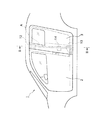
図2は、リアドア3のアウターパネルを取り外して内部を露出した概略図である。同図から理解できるように、リアドア3は、その前端部分に、共に車体上下方向に延びるインパクトバー部材A及び縦レインフォースメント6を有し、この縦レインフォースメント6の外側面には、前後方向に延びる横インパクトバー7が取り付けられている。インパクトバー部材Aは、好ましくは、垂直方向に延びるのがよい。図2の参照符号8は、リアドア3の後端に配置されたドアヒンジ用取付座を示す。
FIG. 2 is a schematic view in which the outer panel of the
図3は、図1のIII−III線に沿った断面図であり、図4は、インパクトバー部材Aを構成するインパクトバー本体5と、その上端及び下端に取り付けられるブラケットの分解斜視図である。これらの図面において、リアドア3は、従来と同様に、アウターパネル10とインナーパネル11とを含む。
3 is a cross-sectional view taken along line III-III in FIG. 1, and FIG. 4 is an exploded perspective view of the impact bar
アウターパネル10とインナーパネル11とで挟まれた内部空間には、リアドア3の前端部分に、アウターパネル10側から順に、縦レインフォースメント6、インパクトバー本体5が配置され、インパクトバー本体5は、上端ブラケット12と下端ブラケット13とセンターブラケット14とを介して、レインフォースメント6に固定されている。
In the internal space sandwiched between the
インパクトバー本体5は高張力鋼からなるパイプ材から作られ、ブラケット12〜14は鉄系金属から作られている。他方、アウターパネル10、インナーパネル11及び縦レインフォースメント6はアルミニウム材材から作られている。
The impact bar
上端ブラケット12は、アウターパネル10側に位置する外側ブラケット要素16と、インナーパネル11側に位置する内側ブラケット要素15との2つの部材で構成され、これらの要素15、16はリベットR及びボルトナットの組み合わせ(以下、ボルトナットの組み合わせを単に「ボルトB」という)によって相互に固定される。リベットRはアルミニウム材製であるのが好ましく、このアルミニウム材製リベットRを用いて、上端ブラケット12が縦レインフォースメント6に締結されている(図3)。
The
上端ブラケット12は、上下方向に延びる形状を有し、内側ブラケット要素15の上方部分には、ドアロック要素であるアッパラッチ18(図3)をボルトBを使って固定するための取付座20が形成されている(図3、図4、図6)。このアッパラッチ18は、リアドア3を閉じたときに、車体側部材であるルーフサイドレール22にボトル止めされたアッパストライカ23と係合して(図3)、リアドア3を閉じ位置で固定する。
The
上端ブラケット12には、また、内側ブラケット要素15の上方部分に、シートベルト25のショルダーアンカ26を固定するためのアンカブラケット27をボルト止めするための座28が形成されている(図5)。
In the
上端ブラケット12は、また、その下方部分に、内外のブラケット要素15、16が共同してインパクトバー本体5の上端部を受け入れる縦穴30(図4)を有し、この縦穴30は、インパクトバー本体5の径に適合する径となるように、外側ブラケット要素16の下方部分にプレス成形により形作られた略半円形断面の縦溝31と、内側ブラケット要素15の下方部分にプレス成形により形作られた略半円形断面の縦溝32とで構成されている。インパクトバー本体5の上端部は、内側ブラケット要素15の縦溝32に受け入れられた状態で溶接により固着される。また、外側ブラケット要素16に対しては、その下に形成したスリット33の部分で溶接されている。
The
下端ブラケット13は、インパクトバー本体5の下端部に対して車体内方側に位置する一つの部材からなり、この下端ブラケット13には略半円形断面の縦溝35がプレス成形により形作られている。インパクトバー本体5の下端部は、下端ブラケット13の縦溝35に受け入れられた状態で溶接により固着される。
The
下端ブラケット13は、リアドア3の下端面に沿って略L字状に屈曲した形状を有するロアラッチレインフォースメント40及びインナーパネル11にリベットR及びボルトBを介して締結される(図9)。
The
ロアラッチレインフォースメント40は、その車体外方に位置する立ち上がりフランジ42を有し、この立ち上がりフランジ42は縦レインフォースメント6の下端にリベットRを介して締結される(図5)。
The
ロアラッチレインフォースメント40の底面には、ドアロック要素であるロアラッチ45(図3、図5)が取り付けられ、このロアラッチ45は、リアドア3を閉じたときに、車体側部材を構成するサイドシェル46にボルト止めされたロアストライカ47と係合して(図3)、リアドア3を閉じ位置で固定する。
A lower latch 45 (FIGS. 3 and 5), which is a door lock element, is attached to the bottom surface of the
ロアラッチレインフォースメント40の車体内方側の縦フランジ48は、その大部分が下端ブラケット13と重なり合い、この重なり合った部分に一対のキャッチャピン49がボルト止めされる(図5、図10)。この一対のキャッチャピン49は、リアドア3と閉じると、サイドシェル46の車体前後方向に離間した一対の位置決め穴50(図3)に中に侵入して、側面衝突時のリアドア3の変位を規制する。
Most of the
センターブラケット14は、インパクトバー本体5の上下方向中央部分に配置され、このインパクトバー本体5の中央部分に対して車体内方側に位置する一つの部材からなる。センターブラケット14には略半円形断面の縦溝50がプレス成形により形作られており、インパクトバー本体5は、センターブラケット14の縦溝50に受け入れられた状態で溶接により固着される。
The
センターブラケット14は、インナーパネル11と縦レインフォースメント6との間に亘って延びる形状を有し、この外端と内端とにそれぞれフランジ51、52が形成されている。センターブラケット14の外側フランジ51は、リベットRを介して縦レインフォースメント6に締結され、他方、内側フランジ52は、リベットR及びボルトBを用いてインナーパネル11に固定されている。
The
インナーパネル11には、下端ブラケット13とセンターブラケット14との間に開口56が形成され、この開口56はシートベルトリトラクタ取付用の穴を構成する。すなわち、図5から理解できるように、シートベルト部材であるシートベルトリトラクタ60はブラケット61に取付られており、このリトラクタ用ブラケット61は上下方向に延びる形状を有する。このブラケット61の上端と下端には、ボトル挿通穴62(下端ボルト挿通穴は図示の関係上現れていない)が形成され、この上下のボルト挿通穴62を通る上下のボルトBを用いて、センターブラケット14と下端ブラケット13とに固定される。つまり、特に図5を参照すると良く理解できるように、上方ボルトBを受け入れる一対のボルト挿通穴66がセンターブラケット14の上端に形成され、また、下方ボルトBを受け入れるボルト挿通穴67が下端ブラケット13の上端に形成されている。
An
以上の構成により、インパクトバー本体5は、上端ブラケット12及び下端ブラケット13と一体となって実質的に側面衝突に対する車体補強部材を構成する。そして、上端ブラケット12は、その上端部分が、図3から理解できるように、上側の車体側部材を構成するルーフサイドレール22とオーバーラップしている。図3の参照符号H1は、上端ブラケット12とルーフサイドレール22とのオーバーラップ部分の高さを示す。また、インパクトバー本体5の下端は、下側の車体側部材を構成するサイドシェル46とオーバーラップする位置まで下方に延びている。図3の参照符号H2は、インパクトバー本体5とサイドシェル46とのオーバーラップ部分の高さを示す。
With the above configuration, the impact bar
このように、インパクトバー本体5は、実質的に、車体強度部材であるルーフサイドレール22及びサイドシェル46にオーバーラップしているため、車体側部に加わる衝撃に対する車体側部の強度を効果的に確保することができる。
Thus, since the impact bar
また、このインパクトバー本体5の実質的な構成要素である上端ブラケット12にアッパラッチ18やシートベルトのショルダーアンカ26を取り付けるようにしてあるため、これらドア機能部品のための補強部材を新たに用意する必要はない。同様に、インパクトバー本体5の下端に設けられて、このインパクトバー本体5の実質的な構成要素を成すセンターブラケット14、下端ブラケット13、シートベルトリトラクタ用ブラケット及びロアラッチレインフォースメント40に、シートベルトリトラクタ60、キャッチャピン49やロアラッチ45を取り付けるようにしてあるため、これらドア機能部品のための補強部材を用意する必要はない。
Further, since the
上述したリアドア3は、インナーパネル11などがアルミニウム材で作られ、また、インパクトバー本体5が高張力鋼から作られ、各種ブラケット12などが鉄系材で作られているため、塗装工程(塗装の乾燥工程)での熱による熱膨張差に基づく相対変位を吸収するために、ホワイトボディーの段階では、リベットRで関連する部材を互いに連結し、また、ボルトBを緩めた状態にしておき、その後、塗装が完了した段階で、ボルトBを締め付けることにより、これに関連する部材を固定するのが好ましい。
In the
また、図4などから分かるように、インパクトバー本体5に湾曲した形状を与えた場合、インパクトバー本体5の曲がり度合いの固体差を吸収するために、下端ブラケット13、センターブラケット14に設けた縦溝35、50の深さを、インパクトバー本体5の径よりも大きく設定するのが好ましい。
Further, as can be seen from FIG. 4 and the like, when the impact bar
以上、本発明の好ましい実施例を図面を参照して説明したが、本発明はこれに限定されるものではない。例えば、インパクトバー本体5をリアドア3の前端部分に配置したが、これに代えて又はこれと共に、フロントドア2の後端部分にインパクトバー本体5を配置するようにしてもよい。また、インパクトバー本体5に加えて、リアドア3やフロントドア2に車体前後方向に延びるインパクトバーを設けるようにしてもよい。
Although the preferred embodiments of the present invention have been described with reference to the drawings, the present invention is not limited to these embodiments. For example, although the impact bar
また、観音開きのサイドドアに本発明を適用した例を説明したが、本発明は、リアドア3が、車体に沿って前後するスライドドア或いはリアドアが上方に向けて開く跳ね上げタイプのドアであっても好適に適用することができる。
Moreover, although the example which applied this invention to the side door of a double door was demonstrated, this invention is a flip door type door which the
更に、上記の実施例では、インパクトバー部材Aは、ルーフサイドレール22とサイドシェル46とにオーバーラップさせているが、そのいずれか一方にだけオーバーラップさせるようにしてもよい。その際には、オーバーラップしない側は、ドアロック部材で衝撃に対する強度を確保することになる。
Further, in the above embodiment, the impact bar member A is overlapped with the
1 車両
2 フロントドア
3 リアドア
5 インパクトバー本体
12 上端ブラケット
13 下端ブラケット(第1ブラケット)
14 センターブラケット
22 ルーフサイドレール
26 シートベルトのショルダーアンカ
27 アンカブラケット
28 アンカブラケット取付座
40 ロアラッチレインフォースメント(第2ブラケット)
45 ロアラッチ(ドアロック部材)
46 サイドシェル
49 キャッチャピン
61 シートベルトリトラクタ用ブラケット
A インパクトバー部材
B ボルトとナットの組み合わせ
R リベット
1
14
45 Lower latch (door lock member)
46
Claims (5)
前記フロントドアの後端部又は前記リアドアの前端部のアウタパネルとインナパネルとで囲まれた内部空間にパイプ部材及び縦レインフォースメントが配設され、
前記パイプ部材はベルトラインを挟んで上下に延び、
前記縦レインフォースメントは、前記パイプ部材に隣接して且つ該パイプ部材に連結して配置され、また、上下方向に延びてその上端及び下端が側面視で車体側部材とオーバーラップし、
前記車体側部材には、該車体側部材と縦レインフォースメントの上端部とがオーバーラップする部位にストライカが配設され、
前記縦レインフォースメントにおける前記パイプ部材よりも上方位置に、前記ストライカと係合してドアを閉状態に保持するためのドアロック部材が設けられていることを特徴とする車両のドア構造。 When the front door and the rear door are opened, the opening for the front seat occupant corresponding to the front door having the outer panel and the inner panel and the opening for the rear seat occupant corresponding to the rear door having the outer panel and the inner panel are opened. , A vehicle door structure that forms one opening without a partition,
The pipe member and the longitudinal reinforcement is arranged in the internal space surrounded by the rear end or the outer panel and the inner panel of the front end portion of the rear door of the front door,
The pipe member extends up and down across the belt line,
The vertical reinforcement is disposed adjacent to the pipe member and connected to the pipe member. The vertical reinforcement extends in the vertical direction, and the upper end and the lower end overlap the vehicle body side member in a side view.
The vehicle body side member is provided with a striker at a portion where the vehicle body side member and the upper end portion of the vertical reinforcement overlap.
A door structure for a vehicle, wherein a door lock member is provided at a position above the pipe member in the vertical reinforcement to engage the striker and hold the door in a closed state.
前記フロントドアの後端部又は前記リアドアの前端部のアウタパネルとインナパネルとで囲まれた内部空間にパイプ部材及び縦レインフォースメントが配設され、 A pipe member and a vertical reinforcement are disposed in an inner space surrounded by an outer panel and an inner panel at the rear end portion of the front door or the front end portion of the rear door,
前記パイプ部材はベルトラインを挟んで上下に延び、 The pipe member extends up and down across the belt line,
前記縦レインフォースメントは、前記パイプ部材に隣接して且つ該パイプ部材に連結して配置され、また、上下方向に延びてその上端及び下端が側面視で車体側部材とオーバーラップし、 The vertical reinforcement is disposed adjacent to the pipe member and connected to the pipe member. The vertical reinforcement extends in the vertical direction, and the upper end and the lower end overlap the vehicle body side member in a side view.
前記車体側部材には、該車体側部材と縦レインフォースメントの上端部とがオーバーラップする部位にストライカが配設され、 The vehicle body side member is provided with a striker at a portion where the vehicle body side member and the upper end portion of the vertical reinforcement overlap.
前記縦レインフォースメントにおける前記パイプ部材よりも上方位置に、前記ストライカと係合してドアを閉状態に保持するためのドアロック部材が設けられ、 A door lock member for engaging the striker and holding the door in a closed state is provided at a position above the pipe member in the vertical reinforcement,
前記縦レインフォースメントには、その上端部に、車室側に膨出し且つ車外側に開放した断面略半円形の縦溝を備えた第1ブラケットを介して前記パイプ部材が車室側から車外側に向けて略半周抱きかかえた状態で隣接配置されると共に前記第1ブラケットに前記ドアロック部品が取り付けられており、 In the vertical reinforcement, the pipe member is connected to the vehicle compartment side from the vehicle compartment side through a first bracket having a longitudinal groove having a substantially semicircular cross section that bulges toward the vehicle compartment side and opens to the vehicle exterior side. The door lock component is attached to the first bracket while being arranged adjacent to the outside in a state of being held in a substantially half-circumferential direction toward the outside,
該ドアロック部材は、平面視したときに前記第1ブラケットと前記縦レインフォースメントとの間に形成される空間に配設され、 The door lock member is disposed in a space formed between the first bracket and the vertical reinforcement when viewed in plan,
更に、 Furthermore,
前記第1ブラケットと前記縦レインフォースメントとに連結された第2ブラケットであって、前記第1ブラケットと前記縦レインフォースメントとの間に亘って延びる第2ブラケットを介して前記ドアロック部材が前記縦レインフォースメントに取り付けられていることを特徴とする車両のドア構造。 The second bracket connected to the first bracket and the vertical reinforcement, wherein the door lock member is interposed via a second bracket extending between the first bracket and the vertical reinforcement. A vehicle door structure attached to the longitudinal reinforcement.
前記フロントドアの後端部及び/又は前記リアドアの前端部に、上下方向に延びる板部材からなる縦レインフォースメントと、 A vertical reinforcement composed of a plate member extending in the vertical direction at the rear end of the front door and / or the front end of the rear door;
該縦レインフォースメントに隣接して配設され、前記フロントドア及び前記リアドアの窓枠の下端縁で規定されるベルトラインを挟んで上下に延びるパイプ部材とを有し、 A pipe member disposed adjacent to the vertical reinforcement and extending vertically across a belt line defined by a lower edge of a window frame of the front door and the rear door;
前記縦レインフォースメントがアルミニウム材から作られ、また、前記パイプ部材が鉄系材から作られており、該パイプ部材が前記縦レインフォースメントに対して、これらパイプ部材と縦レインフォースメントの熱膨張差による相対変位を吸収することのできる締結具を用いて互いに締結されていることを特徴とする車両のドア構造。 The longitudinal reinforcement is made of an aluminum material, and the pipe member is made of an iron-based material, and the pipe member is in contact with the longitudinal reinforcement and heat of the pipe member and the longitudinal reinforcement is increased. A door structure for a vehicle, which is fastened to each other using a fastener capable of absorbing a relative displacement due to an expansion difference.
Priority Applications (1)
| Application Number | Priority Date | Filing Date | Title |
|---|---|---|---|
| JP2005373589A JP4251177B2 (en) | 2005-12-26 | 2005-12-26 | Vehicle door structure |
Applications Claiming Priority (1)
| Application Number | Priority Date | Filing Date | Title |
|---|---|---|---|
| JP2005373589A JP4251177B2 (en) | 2005-12-26 | 2005-12-26 | Vehicle door structure |
Related Parent Applications (1)
| Application Number | Title | Priority Date | Filing Date |
|---|---|---|---|
| JP2002050839A Division JP2003252057A (en) | 2002-02-27 | 2002-02-27 | Door structure for vehicle |
Publications (3)
| Publication Number | Publication Date |
|---|---|
| JP2006096348A JP2006096348A (en) | 2006-04-13 |
| JP2006096348A5 JP2006096348A5 (en) | 2006-08-10 |
| JP4251177B2 true JP4251177B2 (en) | 2009-04-08 |
Family
ID=36236552
Family Applications (1)
| Application Number | Title | Priority Date | Filing Date |
|---|---|---|---|
| JP2005373589A Expired - Lifetime JP4251177B2 (en) | 2005-12-26 | 2005-12-26 | Vehicle door structure |
Country Status (1)
| Country | Link |
|---|---|
| JP (1) | JP4251177B2 (en) |
Families Citing this family (7)
| Publication number | Priority date | Publication date | Assignee | Title |
|---|---|---|---|---|
| JP6071056B2 (en) * | 2013-03-29 | 2017-02-01 | 三井金属アクト株式会社 | Operation relay device for vehicle door latch |
| JP6523395B2 (en) * | 2017-09-21 | 2019-05-29 | 本田技研工業株式会社 | Door structure and vehicle |
| JP7019245B2 (en) * | 2017-12-28 | 2022-02-15 | ダイハツ工業株式会社 | Vehicle sliding door structure |
| JP7159638B2 (en) * | 2018-06-25 | 2022-10-25 | マツダ株式会社 | vehicle door structure |
| JP7081334B2 (en) * | 2018-06-25 | 2022-06-07 | マツダ株式会社 | Vehicle door structure |
| KR20200106396A (en) * | 2019-03-04 | 2020-09-14 | 현대자동차주식회사 | Bending structure and bending device of impact beam |
| KR20230090729A (en) * | 2021-12-15 | 2023-06-22 | 현대자동차주식회사 | Seat belt mounting structure |
-
2005
- 2005-12-26 JP JP2005373589A patent/JP4251177B2/en not_active Expired - Lifetime
Also Published As
| Publication number | Publication date |
|---|---|
| JP2006096348A (en) | 2006-04-13 |
Similar Documents
| Publication | Publication Date | Title |
|---|---|---|
| JP2003252057A (en) | Door structure for vehicle | |
| US9849918B2 (en) | Motor vehicle body | |
| JP4251177B2 (en) | Vehicle door structure | |
| CN100390007C (en) | Rear body structure of vehicle | |
| JP4187260B2 (en) | Hood airbag device for vehicle | |
| JP4715341B2 (en) | Lower body structure of sliding door car | |
| US8205925B2 (en) | Vehicle body reinforcing structure | |
| JPH0872742A (en) | Car body structure of center pillar bottom part of vehicle | |
| US8511731B2 (en) | Vehicle partition side member structure | |
| US20190016392A1 (en) | Center pillar structure for vehicle | |
| JP2006096348A5 (en) | ||
| JP7147395B2 (en) | vehicle rear body structure | |
| JP4058779B2 (en) | Vehicle door structure | |
| JPH08332975A (en) | Rear structure of body | |
| JP4924628B2 (en) | Vehicle side door structure | |
| JP2011098684A (en) | Upper vehicle body structure of vehicle | |
| JP2009184488A (en) | Vehicle body rear part structure for automobile | |
| JP4370508B2 (en) | Roll bar structure of vehicle | |
| JP6597234B2 (en) | Vehicle hinge structure | |
| JP4506268B2 (en) | Rear pillar superstructure of the car body | |
| JP4114454B2 (en) | Vehicle side door structure | |
| JP2020001427A (en) | Vehicle door structure | |
| JP2003175859A (en) | Vehicle body structure | |
| JP4288920B2 (en) | Vehicle side door structure | |
| KR20090061895A (en) | Reinforcing structure of center pillar for automobile |
Legal Events
| Date | Code | Title | Description |
|---|---|---|---|
| A521 | Request for written amendment filed |
Free format text: JAPANESE INTERMEDIATE CODE: A523 Effective date: 20060110 |
|
| A621 | Written request for application examination |
Free format text: JAPANESE INTERMEDIATE CODE: A621 Effective date: 20060110 |
|
| A521 | Request for written amendment filed |
Free format text: JAPANESE INTERMEDIATE CODE: A523 Effective date: 20060622 |
|
| A977 | Report on retrieval |
Free format text: JAPANESE INTERMEDIATE CODE: A971007 Effective date: 20080912 |
|
| A131 | Notification of reasons for refusal |
Free format text: JAPANESE INTERMEDIATE CODE: A131 Effective date: 20080930 |
|
| A521 | Request for written amendment filed |
Free format text: JAPANESE INTERMEDIATE CODE: A523 Effective date: 20081126 |
|
| TRDD | Decision of grant or rejection written | ||
| A01 | Written decision to grant a patent or to grant a registration (utility model) |
Free format text: JAPANESE INTERMEDIATE CODE: A01 Effective date: 20081224 |
|
| A01 | Written decision to grant a patent or to grant a registration (utility model) |
Free format text: JAPANESE INTERMEDIATE CODE: A01 |
|
| A61 | First payment of annual fees (during grant procedure) |
Free format text: JAPANESE INTERMEDIATE CODE: A61 Effective date: 20090106 |
|
| R150 | Certificate of patent or registration of utility model |
Ref document number: 4251177 Country of ref document: JP Free format text: JAPANESE INTERMEDIATE CODE: R150 Free format text: JAPANESE INTERMEDIATE CODE: R150 |
|
| FPAY | Renewal fee payment (event date is renewal date of database) |
Free format text: PAYMENT UNTIL: 20120130 Year of fee payment: 3 |
|
| FPAY | Renewal fee payment (event date is renewal date of database) |
Free format text: PAYMENT UNTIL: 20120130 Year of fee payment: 3 |
|
| FPAY | Renewal fee payment (event date is renewal date of database) |
Free format text: PAYMENT UNTIL: 20130130 Year of fee payment: 4 |
|
| FPAY | Renewal fee payment (event date is renewal date of database) |
Free format text: PAYMENT UNTIL: 20140130 Year of fee payment: 5 |
|
| EXPY | Cancellation because of completion of term |