JP4245397B2 - Roll screen operation method and roll screen - Google Patents
Roll screen operation method and roll screen Download PDFInfo
- Publication number
- JP4245397B2 JP4245397B2 JP2003100528A JP2003100528A JP4245397B2 JP 4245397 B2 JP4245397 B2 JP 4245397B2 JP 2003100528 A JP2003100528 A JP 2003100528A JP 2003100528 A JP2003100528 A JP 2003100528A JP 4245397 B2 JP4245397 B2 JP 4245397B2
- Authority
- JP
- Japan
- Prior art keywords
- rotating
- raw material
- rolls
- roll
- disk
- Prior art date
- Legal status (The legal status is an assumption and is not a legal conclusion. Google has not performed a legal analysis and makes no representation as to the accuracy of the status listed.)
- Expired - Fee Related
Links
Images

Landscapes
- Combined Means For Separation Of Solids (AREA)
Description
【0001】
【発明の属する技術分野】
本発明は、粘性あるいは付着性のある原料であっても高い処理能力にて払い出しを行うことができるようにした、ロールスクリーンの運転方法及びロールスクリーンに関するものである。
【0002】
【従来の技術】
例えば製鉄所での鉄分含有粉塵(ダスト)を処理した際に発生する鉄分含有粉塵よりなる脱水ケーキや、土木・建設現場で副次的に発生した建設発生土などのような原料を篩い分けする設備として、ロールスクリーンが用いられている。ロールスクリーンで篩い分けされた篩下(アンダーサイズ品)は下流工程に供給され、篩上(オーバーサイズ品)はロールスクリーン外部に搬送され排出される。このようなロールスクリーンの一例が、特開2001−212516号公報に示されている。
【0003】
この従来のロールスクリーンは、所定間隔で配置された複数のディスク付き回転ロールを備えている。各ディスク付き回転ロールは、ロール軸線に対して直角をなす複数の中空円板状の回転ディスク(回転ローラ又はフランジとも呼ばれている)がロール軸線方向に間隔をおいてロール外周面に固着(嵌着)されている。これにより、各ディスク付き回転ロールの回転ディスク間に形成される円周溝が、原料の流れ方向に沿ってすなわちロール軸線に対して直角方向、かつ一直線上に整合配置されており、所定の間隔をおいて隣り合う回転ロール及び隣り合う回転ディスク間の円周溝で形成される隙間が「篩目」となっている。
【0004】
そして、原料のうちこの隙間より大きなものは、同一方向に回転する各ディスク付き回転ロールによって該回転ロール上を搬送されてオーバーサイズ品として排出される。一方、前記隙間(篩目)より小さなものは、この隙間を通って払い出されるようになっている。
【0005】
なお、この従来のロールスクリーンは、複数のディスク付き回転ロールにおける1つ置きのディスク付き回転ロール、つまり隣り合うディスク付き回転ロールが系列の異なる駆動装置によって回転駆動されるように構成されている。こうすることで、砕石などの硬い楔状の原料が前記間隙に挟まってロックしても、1系列を停止しても残りの系列が運転を続けることができ、ロールスクリーン全体を停止せずにすむようにしている。
【0006】
【特許文献1】
特開2001−212516号公報(第1図、第4図)
【0007】
【発明が解決しようとする課題】
しかし前述した従来のロールスクリーンでは、各ディスク付き回転ロールを同一方向に回転駆動するようにしたので、解砕作用がほとんど生じないから、粘性原料(例えば脱水ケーキ)、あるいは粘着性のある付着性原料のような、粘性あるいは付着性のある原料の場合には、原料の大部分はディスク付き回転ロール上を移動するだけ、もしくは滞留するだけでディスク付き回転ロール間の隙間に落し込んで払い出すことができないという問題があった。
【0008】
本発明はこのような事情に鑑みてなされたものであり、本発明の目的は、粘性あるいは付着性のある原料であっても高い処理能力にて払い出しを行うことができる、ロールスクリーンの運転方法及びロールスクリーンを提供することにある。
【0009】
【課題を解決するための手段】
前記目的を達成するために、本願発明は次のように構成されている。
【0010】
請求項1の発明は、各ディスク付き回転ロールが互いに所定間隔で配置され、奇数列目に配置された各ディスク付き回転ロール及び偶数列目に配置された各ディスク付き回転ロールを備えたロールスクリーンにより、粘性あるいは付着性のある原料を篩い分けするに際し、隣り合うディスク付き回転ロールを互いに反対方向に回転駆動し、かつ、定期的に回転方向を反転することを予め定められたタイムスケジュールに従って実施する原料挟み込み運転を行い、前記原料挟み込み運転を行った後、前記各ディスク付き回転ロールを同一方向に回転駆動して、ロールスクリーン外部にオーバーサイズ品を排出することを特徴とするロールスクリーンの運転方法である。
【0011】
請求項2の発明は、各ディスク付き回転ロールが互いに所定間隔で配置され、奇数列目に配置された各ディスク付き回転ロール及び偶数列目に配置された各ディスク付き回転ロールを備えたロールスクリーンにより、粘性あるいは付着性のある原料を篩い分けするに際し、隣り合うディスク付き回転ロールを互いに反対方向に回転駆動し、かつ、時間をおいて回転方向を反転することを繰り返す原料挟み込み運転を行うことを特徴とするロールスクリーンの運転方法である。
【0012】
請求項3の発明は、請求項2記載のロールスクリーンの運転方法において、前記原料挟み込み運転を行った後、前記各ディスク付き回転ロールを同一方向に回転駆動して、ロールスクリーン外部にオーバーサイズ品を排出することを特徴とするものである。
【0013】
請求項4の発明は、請求項1〜3のいずれか1項に記載のロールスクリーンの運転方法において、前記各ディスク付き回転ロールに付着する原料をスクレーパで掻き取りながら、前記各ディスク付き回転ロールを回転駆動することを特徴とするものである。
【0014】
請求項5の発明は、各ディスク付き回転ロールが互いに所定間隔で配置されており、奇数列目に配置された各ディスク付き回転ロール及び偶数列目に配置された各ディスク付き回転ロールと、前記各ディスク付き回転ロールの回転駆動源の回転方向を制御して、前記各ディスク付き回転ロールを互いに反対方向に回転させ、かつ、定期的に回転方向を反転させることを予め定められたタイムスケジュールに従って実施する原料挟み込み運転を行う回転方向制御手段とを備え、前記回転方向制御手段は、原料挟み込み運転を行った後にロールスクリーン外部にオーバーサイズ品を排出するに際し、前記各ディスク付き回転ロールを同一方向に回転させる回転方向切替を行うことを特徴とするロールスクリーンである。
【0015】
請求項6の発明は、各ディスク付き回転ロールが互いに所定間隔で配置されており、奇数列目に配置された各ディスク付き回転ロール及び偶数列目に配置された各ディスク付き回転ロールと、前記各ディスク付き回転ロールの回転駆動源の回転方向を制御して、隣り合うディスク付き回転ロールを互いに反対方向に回転させ、かつ、時間をおいて回転方向を反転させることを繰り返す原料挟み込み運転を行う回転方向制御手段とを備えていることを特徴とするロールスクリーンである。
【0016】
請求項7の発明は、請求項6記載のロールスクリーンにおいて、前記回転方向制御手段は、原料挟み込み運転を行った後にロールスクリーン外部にオーバーサイズ品を排出するに際し、前記各ディスク付き回転ロールを同一方向に回転させる回転方向切替を行うことを特徴とするものである。
【0017】
請求項8の発明は、請求項5〜7のいずれか1項に記載のロールスクリーンにおいて、前記各ディスク付き回転ロールに付着する原料を掻き取るスクレーパを備えていることを特徴とするものである。
【0018】
請求項9の発明は、所定間隔で配置された複数のディスク付き回転ロールを備えたロールスクリーンにより粘性あるいは付着性のある原料を篩い分けするに際し、隣り合うディスク付き回転ロールを原料を挟み込むべく互いに反対方向に回転駆動し、かつ、定期的に回転方向を反転することを予め定められたタイムスケジュールに従って実施する原料挟み込み運転を行うロールスクリーンの運転方法であって、前記原料挟み込み運転は、第1の駆動モータによって同一方向に一斉に回転する複数のディスク付き回転ロールに対して、当該複数のディスク付き回転ロールのそれぞれと交互に隣り合い、かつ、第2の駆動モータによって同一方向に一斉に回転する複数のディスク付き回転ロールを反対方向に回転駆動することを特徴とするロールスクリーンの運転方法である。請求項10の発明は、所定間隔で配置された複数のディスク付き回転ロールと、前記各ディスク付き回転ロールの回転駆動源である駆動モータの回転方向を制御して、隣り合うディスク付き回転ロールを原料を挟み込むべく互いに反対方向に回転させ、かつ、定期的に回転方向を反転させることを予め定められたタイムスケジュールに従って行う回転方向制御手段とを備え、前記回転方向制御手段は、第1の駆動モータによって同一方向に一斉に回転する複数のディスク付き回転ロールに対して、当該複数のディスク付き回転ロールのそれぞれと交互に隣り合い、かつ、第2の駆動モータによって同一方向に一斉に回転する複数のディスク付き回転ロールを反対方向に回転させるようにすることを特徴とするロールスクリーンである。請求項11の発明は、請求項5、6、7、8又は10に記載のロールスクリーンにおいて、鉄系材料からなる前記ディスク付き回転ロールの各ディスクが楕円板状であって、楕円の長径bと短径aの比(a/b)が0.63以上を満たす形状であることを特徴とするものである。
【0019】
本発明のロールスクリーンの運転方法、又はロールスクリーンでは、隣り合うディスク付き回転ロールを互いに反対方向に回転駆動するようにしたので、隣り合うディスク付き回転ロール間において粘性あるいは付着性のある原料の大塊を挟み込んで解砕する作用が生じる。これにより粘性あるいは付着性のある原料であってもスムーズにディスク付き回転ロール間の隙間(篩目)を通して払い出すことができ、従来に比べて高い処理能力にて短時間で払い出しを行うことができる。
【0020】
ここで、隣り合うディスク付き回転ロールを互いに反対方向に回転駆動することにより、原料の大塊は、回転ディスク円環状面に接する部分が挟み込まれ、切り取られるようにして解砕されて払い出される。このとき、特に粘性の高い高粘性の原料の場合、やがて、回転ディスクが高粘性の原料の大塊との接触部分でスリップし始め、高粘性の原料に回転ディスクの跡形が残るようになり、挟み込んで解砕する作用が低下して払い出し処理能力が大幅に低下する。
【0021】
そこで、本発明のロールスクリーンの運転方法、又はロールスクリーンでは、互いに反対方向に回転している隣り合うディスク付き回転ロールの回転方向を反転させるようにしたので、回転方向の反転時に原料の大塊を他のディスク付き回転ロール間へ移動させ、該原料の大塊と回転ディスクとの接触部分を更新し、該原料の大塊に対して新たな挟み込みによる解砕作用を生じさせうることで、払い出し処理能力を安定させることができる。その結果、高粘性の原料であっても高い処理能力にて払い出しを行うことができる。この場合、例えば、隣り合うディスク付き回転ロールを、互いに反対方向に10秒間回転駆動し(回転ディスクの周速度は、例えば0.3m/s)、次いで数秒間程度回転停止し、しかる後、回転方向を反転させて10秒間回転駆動する。ディスク付き回転ロール上に原料が投入されると、この投入された原料に対してこのような一連の動作が所定時間繰り返される。
【0022】
また、粘性あるいは付着性のある原料中にオーバーサイズ(スクリーンオーバー)の礫などが含まれる場合、原料挟み込み運転を行うことで隣り合うディスク付き回転ロールを互いに反対方向に回転駆動しているので、原料挟み込み運転時、オーバーサイズの礫などは、ロールスクリーンより排出されずディスク付き回転ロール上に残ることになる。
【0023】
そこで、原料挟み込み運転を行った後、ロールスクリーンに備えられた各ディスク付き回転ロールを同一方向に回転駆動することにより、ロールスクリーン外部へオーバーサイズの礫などを搬送し排出することができる。
【0024】
粘性あるいは付着性のある原料の篩い分けに際し、特に付着性(粘着性)の高い高付着性の原料の場合、処理時間の経過とともにディスク付き回転ロールに原料が付着堆積して、該ディスク付き回転ロールがプレーンロール状になることにより、挟み込んで解砕する作用が低下して払い出し処理能力が低下することになる。
【0025】
そこで、原料をスクレーパで掻き取りながら各ディスク付き回転ロールを回転駆動するようにしたものでは、高付着性の原料の場合でも挟み込んで解砕する作用の低下を防止して高い処理能力にて払い出しを行うことができる。
【0026】
また、鉄系材料からなるディスク付き回転ロールの各ディスクを、楕円板状であって、楕円の長径bと短径aの比が所定値を満たす形状にしたものでは、中空円板状の回転ディスクに比べて挟み込みによる解砕作用が顕著で払い出し処理能力を高めることができる。
【0027】
【発明の実施の形態】
以下、図面を参照して本発明の実施の形態について説明する。
【0028】
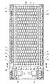
本発明の一実施形態によるロールスクリーンの構成を説明する。図1は本発明に係るロールスクリーンの構成を示す平面図である。なお、図1では理解を容易にするため、原料ホッパ10、原料案内板11、上部フレーム13及び側面カバー12については図示していない。
【0029】
図1に示すように、フレーム3は、前後のフレーム3a,3bと左右のフレーム3c,3dとがそれぞれ対向して矩形状をなしている。ここで、図1における右側(オーバーサイズ品の排出側であって、下流側)を前方し、前方に向かって平面視右側のフレームを右フレーム3dとする。また、左右のフレーム3c,3dの前部側を後部側よりも低位置に設定してあり、フレーム3は前方に向かって下り傾斜している。例えば、このフレーム3の下り傾斜角度は、水平に対して10°に設定されている。そして、左右のフレーム3c,3d間に複数本のディスク付き回転ロール1,1’が所定間隔で回転自在に配置されている。
【0030】
これらのディスク付き回転ロール1,1’は、後フレーム3b側(上流側)より奇数列目に配置されたディスク付き回転ロール1と、偶数列目に配置されたディスク付き回転ロール1’とからなっている。そして、ディスク付き回転ロール1,1’は、ロール軸線に対して直角をなす複数の中空円板状の回転ディスク1aがロール軸線方向に間隔をおいてロール外周面に固着(嵌着)されている。また、隣り合うディスク付き回転ロール1,1’ の回転ディスク1aは、互いの回転ディスク1aが千鳥配置となるように配置されている。
【0031】
4は第1の駆動モータ、5は第2の駆動モータである。後フレーム3b側(上流側)より奇数列目に配置された各ディスク付き回転ロール1は、その軸端部に軸着したスプロケット6に噛合・巻装されたチェーン7を介して第1の駆動モータ4から回転動力が与えられて、所定方向に一斉に回転されるようになっている。また、後フレーム3b側より偶数列目に配置された各ディスク付き回転ロール1’は、その軸端部に軸着したスプロケット6に噛合・巻装されたチェーン7を介して第2の駆動モータ5から回転動力が与えられて、所定方向に一斉に回転されるようになっている。第1の駆動モータ4、スプロケット6及びチェーン7は、奇数列目のディスク付き回転ロール1を回転駆動する駆動機構を構成している。また、第2の駆動モータ5、スプロケット6及びチェーン7は、偶数列目のディスク付き回転ロール1’を回転駆動する駆動機構を構成している。
【0032】
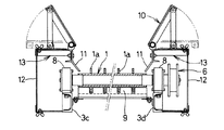
図2は図1のA−A線断面図である。
【0033】
図2に示すように、左右のフレーム3c,3dのそれぞれには、ディスク付き回転ロール1の軸端部を支持するための軸受8が固定されており、ディスク付き回転ロール1は、軸受8によって回転自在に支持されている。偶数列目に配置されたディスク付き回転ロール1’についても同様である。
【0034】
また、各ディスク付き回転ロール1,1’の直下には、図2に示すようにディスク付き回転ロール1,1’との間に櫛歯状をなして隙間を保持するスクレーパ9が配置されている。スクレーパ9は、ボルトにより左右のフレーム3c,3dに交換可能に取り付けられている。なお、スクレーパ9はディスク付き回転ロール1,1’との隙間を調整可能としてもよい。こうすることで、スクレーパ9の摩耗度合いに応じて隙間調整を行うことができ、また、回転ロール1,1’にスクレーパ9を軽く接触させて掻き取り能力を高くすることができる。
【0035】
また、ディスク付き回転ロール1,1’の上方には、図2に示すように、投入された粘性あるいは付着性のある原料をディスク付き回転ロール1,1’上に供給するための原料ホッパ10と、粘性あるいは付着性のある原料が各ディスク付き回転ロール1,1’の両側端部よりこぼれ落ちたり、軸受8にかかったりすることを防ぐための原料案内板11とが設けられている。12は安全用の側面カバーである。原料ホッパ10と原料案内板11は、上部フレーム13に支持されている。上部フレーム13は、左右のフレーム3c,3d上に設けられた上下方向に延びる図示しない垂直フレームに固定されるようになっている。なお、原料ホッパ10は、ロールスクリーンを車両に搭載した際に制限高さを満たすために、図2に示すように、上部フレーム13上に起倒可能に取り付けられている。原料ホッパ10には、例えば油圧ショベルによって粘性あるいは付着性のある原料が投入されるようになっている。
【0036】
また、本実施形態のロールスクリーンはシーケンサ(プログラマブルコントローラ)を備えており、第1の駆動モータ4と第2の駆動モータ5とは、その起動や停止、及び回転方向については、図示しない制御盤内に収納されたシーケンサによって制御されるようになっている。このシーケンサは、後述する第1の原料挟み込み運転に際し、2つの駆動モータ4,5の回転方向を制御して、隣り合うディスク付き回転ロール1,1’を互いに反対方向に回転させる回転方向制御手段を構成している。また、このシーケンサは、後述する第2の原料挟み込み運転に際し、駆動モータ4,5の回転方向を制御して、隣り合うディスク付き回転ロール1,1’を互いに反対方向に回転させ、かつ、時間をおいて回転方向を反転させる回転方向制御手段を構成している。さらに、このシーケンサ(回転方向制御手段)は、ロールスクリーン外部へオーバーサイズ品を搬送し排出するために、第1又は第2の原料挟み込み運転を行った後、各ディスク付き回転ロール1,1’を同一方向(図1において右フレーム3dの側から見て時計回り)に回転させる回転方向切替をも行うものである。
【0037】
このように構成されるロールスクリーンにより、礫を含有する粘性あるいは付着性のある原料を処理する方法について説明する。まず、第1の原料挟み込み運転について説明する。前記シーケンサによって駆動モータ4,5の回転方向を制御することにより、隣り合うディスク付き回転ロール1,1’を互いに反対方向に回転駆動する第1の原料挟み込み運転が行われる。これにより隣り合うディスク付き回転ロール1,1’によって粘性あるいは付着性のある原料の大塊を挟み込んで解砕する作用が生じるので、粘性あるいは付着性のある原料であってもスムーズに回転ロール1,1’間の隙間(篩目)を通して払い出すことができ、従来に比べて高い処理能力にて短時間で払い出しを行うことができる。
【0038】
この場合、特に付着性の高い高付着性の原料のときでも、各ディスク付き回転ロール1,1’に付着する原料をスクレーパ9で掻き取りながらディスク付き回転ロール1,1’を回転駆動するようにしたので、挟み込んで解砕する作用の低下を防止して高い処理能力にて払い出しを行うことができる。
【0039】
第1の原料挟み込み運転の後、各ディスク付き回転ロール1,1’を右フレーム3dの側から見て時計回りに回転駆動させることにより、粘性あるいは付着性のある原料中に含まれるオーバーサイズの礫を搬送して前フレーム3a側(下流側)より排出することができる。
【0040】
次に、第2の原料挟み込み運転について説明する。前記シーケンサによって駆動モータ4,5の回転方向を制御することにより、隣り合うディスク付き回転ロール1,1’を互いに反対方向に回転駆動し、かつ、定期的に回転方向を反転する第2の原料挟み込み運転が行われる。これにより回転方向の反転時に粘性あるいは付着性のある原料の大塊を他のディスク付き回転ロール1,1’間へ移動させ、該原料の大塊と回転ディスク1aとの接触部分を更新し、該原料の大塊に対して新たな挟み込みによる解砕作用を生じさせうることで、払い出し処理能力を安定させることができる。
【0041】
その結果、特に粘性の高い高粘性の原料であっても従来に比べて高い処理能力にて払い出しを行うことができる。この場合、例えば、隣り合うディスク付き回転ロール1,1’を、互いに反対方向に10秒間回転駆動し、次いで3秒間回転を一時停止し、しかる後、回転方向を反転させて10秒間回転駆動する。このように予め定められたタイムスケジュールに従って一連の動作が繰り返される。そして、この第2の原料挟み込み運転の後、各ディスク付き回転ロール1,1’を右フレーム3dの側から見て時計回りに回転駆動させることにより、原料中に含まれるオーバーサイズの礫を搬送して前フレーム3a側より排出することができる。なお、原料挟み込み運転にあたり、回転ロール1,1’を回転駆動する時間は原料性状などに応じて適宜決定することができ、また、繰り返し回数も処理量などに応じて適宜決定することができる。なお、挟み込み運転による原料の払い出しからオーバーサイズ品の排出までの動作を行うには、シーケンサによる自動の運転制御が望ましいものの、一部又は全ての動作についてオペレータの手動操作によって運転制御を行うようにしてもよい。
【0042】
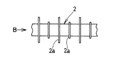
図3は本発明に係るディスク付き回転ロールの他の実施形態を示す正面図、図4は図3のB矢視側面図である。
【0043】
図3及び図4に示すように、このディスク付き回転ロール2は、中空円板状の回転ディスク1aとは違って、ロール外周面に固着された中空楕円板状の回転ディスク2aを有している。また、ディスク付き回転ロール2における隣り合う回転ディスク2aの位相は、90度ずらしてある。このようなディスク付き回転ロール2を備えることにより、中空円板状の回転ディスク1aを有するものに比べて挟み込みによる解砕作用を高めることができ、より高い処理能力を得ることができる。
【0044】
この場合、回転ディスク2aにおける楕円の長径の値をb、短径の値をaとすると、回転ディスク2aの形状は(a/b)≧0.63となるように設定することがよい。こうすることで、隣り合うディスク付き回転ロール2におけるロール軸と回転ディスク2aとの双方に、隣り合う回転ロール2間の隙間(篩目)に相当する直径の球を接触させた場合のロール軸と回転ディスク2a上の接点に引いた両接線のなす角度α(ニップアングル、あるいは、くい込み角度と呼ばれる)が約25°以上となる。これにより、原料挟み込み運転を行う際に、篩目以上の礫を噛み込みにくくするという効果が得られる。礫が噛み込みにくい条件であるニップアングルα≧25°という値は、楕円板状の回転ディスク2aを有する回転ロール2が鉄系材料からなる場合において礫との摩擦係数を考慮して経験的に導き出した値である。なお、楕円板状の回転ディスク2aを有する回転ロール2を用いる場合、隣り合う回転ロール2における回転ディスク2aの位相を回転数により調整するようにすれば、隣り合う回転ロール2において回転ディスク2aを千鳥配置する必要はない。
【0045】
【発明の効果】
以上述べたように、本発明のロールスクリーンの運転方法又はロールスクリーンによれば、粘性あるいは付着性のある原料であってもスムーズにディスク付き回転ロール間の隙間を通して払い出すことができ、従来に比べて高い処理能力にて短時間で払い出しを行うことができる。
【図面の簡単な説明】
【図1】本発明に係るロールスクリーンの構成を示す平面図である。
【図2】図1のA−A線断面図である。
【図3】図3は本発明に係るディスク付き回転ロールの他の実施形態を示す正面図である。
【図4】図3のB矢視側面図である。
【符号の説明】
1,1’,2…ディスク付き回転ロール 1a,2a…回転ディスク 3…フレーム 3a…前フレーム 3b…後フレーム 3c…左フレーム 3d…右フレーム 4…第1の駆動モータ 5…第2の駆動モータ 6…スプロケット 7…チェーン 8…軸受 9…スクレーパ 10…原料ホッパ 11…原料案内板12…側面カバー 13…上部フレーム[0001]
BACKGROUND OF THE INVENTION
The present invention relates to a method for operating a roll screen and a roll screen that can be dispensed with a high throughput even if the material is viscous or adherent.
[0002]
[Prior art]
For example, sieving raw materials such as dehydrated cake made of iron-containing dust generated when iron-containing dust (dust) is processed at steelworks and construction-generated soil secondary to civil engineering and construction sites are screened. A roll screen is used as equipment. The sieve (undersized product) sieved by the roll screen is supplied to the downstream process, and the sieve (oversized product) is conveyed outside the roll screen and discharged. An example of such a roll screen is disclosed in Japanese Patent Application Laid-Open No. 2001-212516.
[0003]
This conventional roll screen includes a plurality of disc-equipped rotating rolls arranged at predetermined intervals. Each rotary roll with a disk has a plurality of hollow disk-shaped rotary disks (also called rotary rollers or flanges) that are perpendicular to the roll axis, and are fixed to the outer peripheral surface of the roll at intervals in the roll axis direction ( Fitted). Thereby, the circumferential groove formed between the rotating disks of the rotating rolls with each disk is aligned and aligned along the flow direction of the raw material, that is, in a direction perpendicular to the roll axis and in a straight line. The gap formed by the circumferential grooves between the adjacent rotating rolls and the adjacent rotating disks is “sieving”.
[0004]
And the thing larger than this clearance gap among raw materials is conveyed on this rotary roll by each rotary roll with a disk rotating in the same direction, and is discharged | emitted as an oversized goods. On the other hand, a thing smaller than the said clearance gap (sieve) is paid out through this clearance gap.
[0005]
In addition, this conventional roll screen is configured such that every other rotary roll with a disk among a plurality of rotary rolls with a disk, that is, adjacent rotary rolls with a disk are rotationally driven by different driving devices. By doing this, even if a hard wedge-shaped raw material such as crushed stone is caught in the gap and locked, even if one series is stopped, the remaining series can continue to operate, and the entire roll screen is not stopped. I am trying.
[0006]
[Patent Document 1]
JP 2001-212516 A (FIGS. 1 and 4)
[0007]
[Problems to be solved by the invention]
However, in the above-described conventional roll screen, since each rotary roll with a disk is driven to rotate in the same direction, there is almost no crushing action, so a viscous raw material (for example, dehydrated cake) or sticky adhesion In the case of a raw material that is viscous or adherent, such as a raw material, most of the raw material only moves on the rotating roll with a disk or stays and drops into the gap between the rotating rolls with a disk to be discharged. There was a problem that I could not.
[0008]
The present invention has been made in view of such circumstances, and an object of the present invention is to operate a roll screen that can perform dispensing with a high processing capacity even if it is a viscous or adherent raw material. And providing a roll screen.
[0009]
[Means for Solving the Problems]
In order to achieve the above object, the present invention is configured as follows.
[0010]
According to the first aspect of the present invention, each of the rotating rolls with a disk is arranged at a predetermined interval, and each of the rotating rolls with a disk arranged in the odd rows and the rotating roll with the disks arranged in the even rows. more, when sieved raw materials with a viscous or adherent, rotates the rotation with adjacent disk rolls in opposite directions to each other, and, in accordance with a predetermined time schedule to reverse the regular rotation direction After performing the raw material sandwiching operation to be performed, and after performing the raw material sandwiching operation, the rotary roll with each disk is rotationally driven in the same direction, and the oversized product is discharged outside the roll screen. It is a driving method.
[0011]
According to a second aspect of the present invention, there is provided a roll screen provided with the rotary rolls with disks arranged in the odd rows and the rotary rolls with discs arranged in the even rows. performed more, when sieved raw materials with a viscous or adherent, rotates the rotation with adjacent disk rolls in opposite directions to each other, and the raw material sandwiched operation repeated reversing the direction of rotation at a time It is the operating method of the roll screen characterized by this.
[0012]
According to a third aspect of the present invention, in the roll screen operating method according to the second aspect, after the raw material sandwiching operation is performed, the rotary rolls with the respective disks are rotationally driven in the same direction, and the oversized product is provided outside the roll screen. It is characterized by discharging.
[0013]
The invention of claim 4 is the operation method of the roll screen according to any one of
[0014]
In the invention of claim 5, the rotating rolls with disks are arranged at predetermined intervals, the rotating rolls with disks arranged in odd rows and the rotating rolls with discs arranged in even rows , According to a predetermined time schedule, the rotation direction of the rotation drive source of each rotary roll with a disk is controlled, the rotary rolls with each disk are rotated in opposite directions, and the rotation direction is periodically reversed. and a rotation direction control means for performing feed pinch operation performed, the direction control means, upon discharging the oversize products in the shade outside after the raw material pinching operation, the same direction of the rotating roll with each disc The roll screen is characterized in that the direction of rotation is rotated.
[0015]
In the invention of
[0016]
Same invention of
[0017]
The invention according to
[0018]
According to the ninth aspect of the present invention, when a raw material having viscosity or adhesiveness is screened by a roll screen having a plurality of rotating rolls with disks arranged at predetermined intervals, adjacent rotating rolls with disks are arranged to sandwich the raw materials. An operation method of a roll screen that performs a raw material sandwiching operation that performs rotational driving in the opposite direction and periodically reverses the rotational direction according to a predetermined time schedule, wherein the raw material sandwiching operation includes: A plurality of rotating rolls with disks that rotate simultaneously in the same direction by the drive motor of the disk are alternately adjacent to each of the rotating rolls with disks and simultaneously rotated in the same direction by the second driving motor. A roll characterized in that a plurality of rotating rolls with discs are driven to rotate in opposite directions We are a clean method of operation. The invention according to
[0019]
In the roll screen operating method or roll screen of the present invention, the adjacent rotary rolls with disks are driven to rotate in opposite directions, so that a large amount of raw material having viscosity or adhesion between the adjacent rotary rolls with disks. The action which pinches and breaks up a lump occurs. As a result, even raw materials with viscosity or adhesion can be smoothly dispensed through the gaps (sieving mesh) between the rotating rolls with a disc, and can be dispensed in a short time with a higher processing capacity than before. it can.
[0020]
Here, by rotating the rotating rolls with disks adjacent to each other in the opposite directions, the large mass of the raw material is sandwiched and cut out so that the portion in contact with the rotating disk annular surface is sandwiched. At this time, particularly in the case of a highly viscous raw material, the rotating disk begins to slip at the contact portion with the large mass of the highly viscous raw material, and a trace of the rotating disk remains on the highly viscous raw material. The action of sandwiching and crushing is reduced, and the payout processing capacity is greatly reduced.
[0021]
Therefore, in the operation method of the roll screen of the present invention or the roll screen, the rotation direction of the adjacent rotary rolls with disks rotating in the opposite directions is reversed. Is moved between the rotating rolls with other discs, the contact portion between the mass of the raw material and the rotating disc is updated, and the crushing action by the new sandwiching can be caused to the mass of the raw material, The payout processing capacity can be stabilized. As a result, even a highly viscous raw material can be dispensed with a high processing capacity. In this case, for example, adjacent rotating rolls with disks are driven to rotate in opposite directions for 10 seconds (the peripheral speed of the rotating disk is, for example, 0.3 m / s), and then stopped for about several seconds. The direction is reversed and rotationally driven for 10 seconds. When a raw material is put on a rotating roll with a disk, such a series of operations is repeated for a predetermined time with respect to the supplied raw material.
[0022]
In addition, when oversized (screen over) gravel is included in the raw material with viscosity or adhesion, the rotating rolls with adjacent disks are driven to rotate in opposite directions by performing the raw material sandwiching operation. During the raw material sandwiching operation, oversized gravel is not discharged from the roll screen, but remains on the rotating roll with disk.
[0023]
Therefore, after the raw material sandwiching operation is performed, the oversized gravel and the like can be transported and discharged to the outside of the roll screen by rotationally driving the rotating rolls with disks provided in the roll screen in the same direction.
[0024]
When sieving viscous or adherent raw materials, especially in the case of highly adherent (adhesive) highly adherent raw materials, the raw material adheres to and accumulates on a rotating roll with a disc as the processing time elapses. By making the roll into a plain roll shape, the action of sandwiching and crushing is reduced, and the payout processing capacity is reduced.
[0025]
Therefore, in the case of rotating the rotating roll with each disk while scraping the raw material with a scraper, even if it is a highly adherent raw material, it prevents the reduction of the action of pinching and crushing and pays out with high processing capacity It can be performed.
[0026]
In addition, each disk of a rotating roll with a disk made of an iron-based material has an elliptical plate shape in which the ratio of the major axis b to the minor axis a satisfies a predetermined value. Compared to the disk, the crushing action by pinching is remarkable, and the payout processing capacity can be enhanced.
[0027]
DETAILED DESCRIPTION OF THE INVENTION
Embodiments of the present invention will be described below with reference to the drawings.
[0028]
A configuration of a roll screen according to an embodiment of the present invention will be described. FIG. 1 is a plan view showing a configuration of a roll screen according to the present invention. In FIG. 1, the
[0029]
As shown in FIG. 1, the frame 3 has a rectangular shape with the front and
[0030]
These rotary rolls 1 and 1 ′ with disks are composed of
[0031]
Reference numeral 4 denotes a first drive motor, and 5 denotes a second drive motor. The rotating rolls with
[0032]
2 is a cross-sectional view taken along line AA in FIG.
[0033]
As shown in FIG. 2, a
[0034]
Further, as shown in FIG. 2, a scraper 9 that forms a comb-like shape and holds a gap between the rotary rolls 1 and 1 ′ with disks is disposed immediately below the rotary rolls 1 and 1 ′ with disks. Yes. The scraper 9 is attached to the left and
[0035]
Further, as shown in FIG. 2, a
[0036]
Further, the roll screen of the present embodiment includes a sequencer (programmable controller), and the first drive motor 4 and the second drive motor 5 have a control panel (not shown) for the start and stop and the rotation direction. It is controlled by a sequencer housed inside. This sequencer controls the direction of rotation of the two drive motors 4 and 5 and rotates adjacent
[0037]
A method for treating a viscous or adherent raw material containing gravel with the roll screen configured as described above will be described. First, the first raw material sandwiching operation will be described. By controlling the rotation direction of the drive motors 4 and 5 by the sequencer, a first raw material sandwiching operation is performed in which the adjacent rotary rolls 1 and 1 ′ with disks are rotated in opposite directions. As a result, the adjoining rotary rolls 1 and 1 ′ with discs have a function of sandwiching and crushing a large mass of the raw material having viscosity or adhesion, so that even if the raw material has viscosity or adhesion, the
[0038]
In this case, the rotating
[0039]
After the first raw material sandwiching operation, each of the
[0040]
Next, the second raw material sandwiching operation will be described. By controlling the rotation direction of the drive motors 4 and 5 by the sequencer, the second raw material which rotates the adjacent
[0041]
As a result, even a highly viscous material having a particularly high viscosity can be dispensed with a higher processing capacity than in the past. In this case, for example, the adjacent
[0042]
FIG. 3 is a front view showing another embodiment of the rotating roll with a disk according to the present invention, and FIG. 4 is a side view as seen in the direction of arrow B in FIG.
[0043]
As shown in FIGS. 3 and 4, this disc-equipped
[0044]
In this case, if the value of the major axis of the ellipse in the
[0045]
【The invention's effect】
As described above, according to the operation method or roll screen of the roll screen of the present invention, even a viscous or adherent raw material can be smoothly discharged through the gap between the rotating rolls with a disk. Dispensing can be performed in a short time with a higher processing capacity.
[Brief description of the drawings]
FIG. 1 is a plan view showing a configuration of a roll screen according to the present invention.
FIG. 2 is a cross-sectional view taken along line AA in FIG.
FIG. 3 is a front view showing another embodiment of a rotating roll with a disk according to the present invention.
4 is a side view as viewed in the direction of arrow B in FIG. 3;
[Explanation of symbols]
DESCRIPTION OF
Claims (7)
Priority Applications (1)
| Application Number | Priority Date | Filing Date | Title |
|---|---|---|---|
| JP2003100528A JP4245397B2 (en) | 2003-04-03 | 2003-04-03 | Roll screen operation method and roll screen |
Applications Claiming Priority (1)
| Application Number | Priority Date | Filing Date | Title |
|---|---|---|---|
| JP2003100528A JP4245397B2 (en) | 2003-04-03 | 2003-04-03 | Roll screen operation method and roll screen |
Publications (2)
| Publication Number | Publication Date |
|---|---|
| JP2004305843A JP2004305843A (en) | 2004-11-04 |
| JP4245397B2 true JP4245397B2 (en) | 2009-03-25 |
Family
ID=33464637
Family Applications (1)
| Application Number | Title | Priority Date | Filing Date |
|---|---|---|---|
| JP2003100528A Expired - Fee Related JP4245397B2 (en) | 2003-04-03 | 2003-04-03 | Roll screen operation method and roll screen |
Country Status (1)
| Country | Link |
|---|---|
| JP (1) | JP4245397B2 (en) |
Families Citing this family (5)
| Publication number | Priority date | Publication date | Assignee | Title |
|---|---|---|---|---|
| JP2006247537A (en) * | 2005-03-11 | 2006-09-21 | Raito Kogyo Co Ltd | Cutting screen device |
| JP4889561B2 (en) * | 2007-05-10 | 2012-03-07 | 株式会社アーステクニカ | Roll screen |
| CN102950104B (en) * | 2011-08-31 | 2015-11-11 | 北京昊海天际科技有限公司 | Be applicable to the disc screen of domestic waste and changing food waste |
| FI129310B (en) * | 2019-07-12 | 2021-11-30 | Tana Oy | Screen |
| CN117920582B (en) * | 2024-02-02 | 2026-01-30 | 中煤科工集团唐山研究院有限公司 | A screening device |
-
2003
- 2003-04-03 JP JP2003100528A patent/JP4245397B2/en not_active Expired - Fee Related
Also Published As
| Publication number | Publication date |
|---|---|
| JP2004305843A (en) | 2004-11-04 |
Similar Documents
| Publication | Publication Date | Title |
|---|---|---|
| JP4245397B2 (en) | Roll screen operation method and roll screen | |
| JP4889561B2 (en) | Roll screen | |
| EP3500376B1 (en) | Self-cleaning roller screen | |
| CN109333747B (en) | a paving machine | |
| JP4261314B2 (en) | Roll screen | |
| RU2687666C1 (en) | Roller screen | |
| JPH091071A (en) | Discharge device with sieve for adhesive raw material and method for discharging sieve from adhesive raw material | |
| CN112170157B (en) | Non-blocking screening machine | |
| CN212702185U (en) | Lime stone screening crushing system | |
| JP2004074056A (en) | Roll screen and method of operating the same, and moving type generated soil stabilization treatment equipment having the same mounted thereon | |
| RU2711603C2 (en) | Clay cleaning device | |
| GB1572464A (en) | Apparatus for applying particulate material to food products | |
| JP2684535B2 (en) | Rough stone recovery plant | |
| RU2101098C1 (en) | Device for separating material flow into size fractions | |
| CN215902147U (en) | Roller way type screening equipment | |
| JPH0335992B2 (en) | ||
| CN219135629U (en) | Material arranging equipment for semiconductive buffer water blocking tape | |
| JP2001321724A (en) | Classifying feeder apparatus for rock | |
| CN221335195U (en) | High-efficiency roller type fine particle size screening machine | |
| CN111250206A (en) | A bionic crushing mechanism | |
| CA2929712C (en) | A self cleaning apparatus for a belt conveyor | |
| RU2060017C1 (en) | Apparatus for separating contaminants from leaf tobacco | |
| CN222447172U (en) | A rolling screen device and crushing system for sample crushing pre-treatment | |
| JP2729590B2 (en) | Discharge device with sieve for adhesive raw material and method for discharging sieve from adhesive raw material | |
| JP2020179324A (en) | Table type raw material discharge apparatus and raw material discharge system using the same |
Legal Events
| Date | Code | Title | Description |
|---|---|---|---|
| A711 | Notification of change in applicant |
Free format text: JAPANESE INTERMEDIATE CODE: A712 Effective date: 20050613 |
|
| A621 | Written request for application examination |
Free format text: JAPANESE INTERMEDIATE CODE: A621 Effective date: 20050916 |
|
| RD02 | Notification of acceptance of power of attorney |
Free format text: JAPANESE INTERMEDIATE CODE: A7422 Effective date: 20050916 |
|
| A521 | Request for written amendment filed |
Free format text: JAPANESE INTERMEDIATE CODE: A523 Effective date: 20050930 |
|
| A977 | Report on retrieval |
Free format text: JAPANESE INTERMEDIATE CODE: A971007 Effective date: 20070717 |
|
| A131 | Notification of reasons for refusal |
Free format text: JAPANESE INTERMEDIATE CODE: A131 Effective date: 20070724 |
|
| A521 | Request for written amendment filed |
Free format text: JAPANESE INTERMEDIATE CODE: A523 Effective date: 20070910 |
|
| A131 | Notification of reasons for refusal |
Free format text: JAPANESE INTERMEDIATE CODE: A131 Effective date: 20071009 |
|
| A521 | Request for written amendment filed |
Free format text: JAPANESE INTERMEDIATE CODE: A523 Effective date: 20071210 |
|
| A131 | Notification of reasons for refusal |
Free format text: JAPANESE INTERMEDIATE CODE: A131 Effective date: 20080108 |
|
| A521 | Request for written amendment filed |
Free format text: JAPANESE INTERMEDIATE CODE: A523 Effective date: 20080306 |
|
| A521 | Request for written amendment filed |
Free format text: JAPANESE INTERMEDIATE CODE: A821 Effective date: 20080630 |
|
| RD02 | Notification of acceptance of power of attorney |
Free format text: JAPANESE INTERMEDIATE CODE: A7422 Effective date: 20080630 |
|
| RD04 | Notification of resignation of power of attorney |
Free format text: JAPANESE INTERMEDIATE CODE: A7424 Effective date: 20080709 |
|
| A131 | Notification of reasons for refusal |
Free format text: JAPANESE INTERMEDIATE CODE: A131 Effective date: 20081021 |
|
| A521 | Request for written amendment filed |
Free format text: JAPANESE INTERMEDIATE CODE: A523 Effective date: 20081204 |
|
| TRDD | Decision of grant or rejection written | ||
| A01 | Written decision to grant a patent or to grant a registration (utility model) |
Free format text: JAPANESE INTERMEDIATE CODE: A01 Effective date: 20090106 |
|
| A01 | Written decision to grant a patent or to grant a registration (utility model) |
Free format text: JAPANESE INTERMEDIATE CODE: A01 |
|
| A61 | First payment of annual fees (during grant procedure) |
Free format text: JAPANESE INTERMEDIATE CODE: A61 Effective date: 20090106 |
|
| R150 | Certificate of patent or registration of utility model |
Ref document number: 4245397 Country of ref document: JP Free format text: JAPANESE INTERMEDIATE CODE: R150 Free format text: JAPANESE INTERMEDIATE CODE: R150 |
|
| FPAY | Renewal fee payment (event date is renewal date of database) |
Free format text: PAYMENT UNTIL: 20120116 Year of fee payment: 3 |
|
| FPAY | Renewal fee payment (event date is renewal date of database) |
Free format text: PAYMENT UNTIL: 20120116 Year of fee payment: 3 |
|
| FPAY | Renewal fee payment (event date is renewal date of database) |
Free format text: PAYMENT UNTIL: 20130116 Year of fee payment: 4 |
|
| FPAY | Renewal fee payment (event date is renewal date of database) |
Free format text: PAYMENT UNTIL: 20130116 Year of fee payment: 4 |
|
| FPAY | Renewal fee payment (event date is renewal date of database) |
Free format text: PAYMENT UNTIL: 20140116 Year of fee payment: 5 |
|
| FPAY | Renewal fee payment (event date is renewal date of database) |
Free format text: PAYMENT UNTIL: 20150116 Year of fee payment: 6 |
|
| LAPS | Cancellation because of no payment of annual fees |