JP4227239B2 - Pneumatic tire - Google Patents
Pneumatic tire Download PDFInfo
- Publication number
- JP4227239B2 JP4227239B2 JP07353499A JP7353499A JP4227239B2 JP 4227239 B2 JP4227239 B2 JP 4227239B2 JP 07353499 A JP07353499 A JP 07353499A JP 7353499 A JP7353499 A JP 7353499A JP 4227239 B2 JP4227239 B2 JP 4227239B2
- Authority
- JP
- Japan
- Prior art keywords
- tire
- groove
- lug groove
- equatorial plane
- center region
- Prior art date
- Legal status (The legal status is an assumption and is not a legal conclusion. Google has not performed a legal analysis and makes no representation as to the accuracy of the status listed.)
- Expired - Fee Related
Links
Images


Landscapes
- Tires In General (AREA)
Description
【0001】
【発明の属する技術分野】
本発明は空気入りタイヤに係り、特に、建設車両等に装着される重荷重車両に用いられるクラウン部の耐久性を向上することのできるラグパターンを有した空気入りタイヤを提供することが目的である。
【0002】
【従来の技術】
建設車両に用いられる空気入りタイヤにおいては、タイヤセンター部にタイヤ周方向に実質上連続する陸部を有するラグ溝パターンが主流である。
【0003】
このようなラグ溝パターンでは、タイヤセンター部での放熱効果が小さく、タイヤセンター部が高く、ショルダー部が低い温度分布となる。
【0004】
【発明が解決しようとする課題】
クラウン部の耐久性を向上させるためには、クラウン部の温度の低減、即ち、走行による温度上昇を抑えることが効果的であり、その手法として、従来では、低発熱性のトレッドコンパウンドを使用したり、トレッドのボリュームダウン(溝深さ低減、ネガティブ比低減)等が行われてきた。
【0005】
しかしながら、従来技術では、いずれの場合でもクラウン部の耐久性(耐ヒートセパレーション性、耐カットセパレーション性)が向上する反面、トレッドの耐摩耗性が低下するという二律背反の性格を持っていた。
【0006】
本発明は上記事実を考慮し、トレッドの耐摩耗性を損なうこと無く、トレッドのクラウン部の耐久性を向上することのできるラグ溝パターンを有する空気入りタイヤを提供することが目的である。
【0007】
【課題を解決するための手段】
請求項1に記載の発明は、ショルダー側からタイヤ赤道面へ向かって延びる主ラグ溝をタイヤ周方向に複数有すると共に、トレッド中央領域においてタイヤ周方向に実質的に連続して延在する陸部を有するラグパターンを有する空気入りタイヤにおいて、タイヤ接地最大幅の30%以内に対応するセンター領域に、溝深さがタイヤ赤道面に向かって漸減する補助ラグ溝を前記主ラグ溝に延長して設け、前記センター領域のネガティブ率を10〜35%とし、前記補助ラグ溝の前記センター領域の幅方向端部からタイヤ赤道面に向かう溝幅中心線のタイヤ赤道面となす角度を40〜55°とした、ことを特徴としている。
【0008】
次に、請求項1に記載の空気入りタイヤの作用を説明する。
【0009】
トレッド部の温度は、タイヤ転動時の繰り返し変形(圧縮と曲げ)による発熱と、タイヤパターン表面での放熱量によって決まる。
【0010】
請求項1に記載の空気入りタイヤでは、トレッドのセンター領域に補助ラグ溝を配置したので、センター領域の陸部のボリュームが低減されて発熱量が減少すると共に、溝面積が増加(溝ペリフェリが増加)することによって放熱量が増加するので、タイヤ転動時のセンター領域の温度上昇を抑えることができる。
【0011】
なお、センター領域の溝面積を単純に増加すると、センター領域のラグ剛性が低下して耐摩耗性が低下するが、補助ラグ溝の溝深さをタイヤ赤道面に向けて除々に浅くすることで剛性の低下を抑えることができ、耐摩耗性が確保される。
また、請求項1に記載の空気入りタイヤでは、補助ラグ溝のセンター領域の端部からタイヤ赤道面に向かう溝幅中心線とタイヤ赤道面とのなす角度を40〜55°としたので、センター領域の温度上昇抑制効果を確保しつつ、周方向のトラクションを確保することができる。なお、補助ラグ溝の溝幅中心線とタイヤ赤道面とのなす角度が55°を越えると温度上昇抑制効果が不足し、補助ラグ溝の溝幅中心線とタイヤ赤道面とのなす角度が40°未満になると、周方向のトラクションが不足する。
【0012】
なお、空気入りタイヤは、それぞれのサイズに応じて、JATMA(日本)、TRA(米国)及びETRTO(欧州)などが発行する規格に定められた標準リムに装着して使用され、この標準リムが通常正規リムと称される。
【0013】
本明細書でもこの慣用呼称に従い、「正規リム」とは米国のタイヤとリムの協会TRAが発行する1998年版のYEAR BOOKに定められた適用サイズにおける標準リムを指す。
【0014】
同様に、「正規荷重」及び「正規内圧」とは、米国のタイヤとリムの協会TRAが発行する1998年版のYEAR BOOKに定められた適用サイズ・プライレーティングにおける最大荷重及び最大荷重に対応する空気圧を指す。
【0015】
また、本明細書において、「タイヤ接地最大幅」とは、タイヤを「正規リム」にリム組みして「正規内圧」を充填し、「正規荷重」を静的に負荷したときのトレッドのタイヤ軸方向の接地最大幅を指す。
【0016】
ここで、荷重とは下記規格に記載されている適用サイズにおける単輪の最大荷重(最大負荷能力)のことであり、内圧とは下記規格に記載されている適用サイズにおける単輪の最大荷重(最大負荷能力)に対応する空気圧のことであり、リムとは下記規格に記載されている適用サイズにおける標準リム(または”Approved Rim "、"Recommended Rim' )のことである。
【0017】
そして規格とは、タイヤが生産又は使用される地域に有効な産業規格によって決められている。例えば、アメリカ合衆国では”The Tire and Rim Association Inc. のYear Book"であり、欧州では”The European Tire and Rim Technical OrganizationのStandards Manual”であり、日本では日本自動車タイヤ協会の”JATMA Year Book"にて規定されている。
【0018】
請求項2に記載の発明は、ショルダー側からタイヤ赤道面へ向かって延びる主ラグ溝をタイヤ周方向に複数有すると共に、トレッド中央領域においてタイヤ周方向に実質的に連続して延在する陸部を有するラグパターンを有する空気入りタイヤにおいて、タイヤ接地最大幅の30%以内に対応するセンター領域に、溝深さがタイヤ赤道面に向かって漸減する補助ラグ溝を、前記主ラグ溝とは独立して設け、前記センター領域のネガティブ率を10〜35%としたことを特徴としている。
【0019】
トレッド部の温度は、タイヤ転動時の繰り返し変形(圧縮と曲げ)による発熱と、タイヤパターン表面での放熱量によって決まる。
【0020】
請求項2に記載の空気入りタイヤでは、トレッドのセンター領域に補助ラグ溝を配置したので、センター領域の陸部のボリュームが低減されて発熱量が減少すると共に、溝面積が増加(溝ペリフェリが増加)することによって放熱量が増加するので、タイヤ転動時のセンター領域の温度上昇を抑えることができる。
【0021】
なお、センター領域の溝面積を単純に増加すると、センター領域のラグ剛性が低下して耐摩耗性が低下するが、補助ラグ溝の溝深さをタイヤ赤道面に向けて除々に浅くすることで剛性の低下を抑えることができ、耐摩耗性が確保される。
【0022】
また、主ラグ溝と独立して設けられる補助ラグ溝は、周方向に間隔をおいて配置される主ラグ溝間に配置することが好ましい。
【0023】
請求項3に記載の発明は、請求項1または請求項2に記載の空気入りタイヤにおいて、前記補助ラグ溝の溝深さが、前記主ラグ溝の最大深さの45〜70%であることを特徴としている。
【0024】
次に、請求項3に記載の空気入りタイヤの作用を説明する。
【0025】
補助ラグ溝の溝深さを主ラグ溝の最大深さの45〜70%としたので、センター領域の温度上昇抑制効果を得つつ、センター領域の剛性を確保することができる。
【0026】
なお、補助ラグ溝の溝深さが主ラグ溝の最大深さの45%未満になると、温度上昇抑制効果が不足し、補助ラグ溝の溝深さが主ラグ溝の最大深さの70%を越えると、センター領域の剛性が不足する。
【0031】
【発明の実施の形態】
[第1の実施形態]
本発明の空気入りタイヤの第1の実施形態を図1(A),(B)にしたがって説明する。
【0032】
図1(A),(B)に示すように、本実施形態の空気入りタイヤ10のトレッド12には、ショルダー部18からタイヤ赤道面CLへ向かって延びる主ラグ溝20と、この主ラグ溝20のタイヤ赤道面CL側の端部に連続して設けられる補助ラグ溝22が、タイヤ周方向(矢印B方向)に間隔を開けて形成されており、トレッド中央領域においては陸部16がタイヤ周方向に実質的に連続して延在している。
【0033】
ここで、トレッド12において、タイヤ接地最大幅Wの30%以内に対応する領域をセンター領域24、その両側の領域を両側領域25としたときに、主ラグ溝20は両側領域25に設けられており、補助ラグ溝22は、その殆どの部分がセンター領域24に設けられている。
【0034】
なお、センター領域24のネガティブ率は、10〜35%の範囲内に設定されている。
【0035】
補助ラグ溝22は、その溝深さ が主ラグ溝20の最大深さDの45〜70%の範囲内に設定されていると共に、溝深さdがタイヤ赤道面CLに向かって漸減している。
【0036】
本実施形態の主ラグ溝20は、タイヤ幅方向(矢印A方向)に対して傾斜(タイヤ周方向に対する角度β。)している。
【0037】
センター領域24の端部からタイヤ赤道面CLに向かう補助ラグ溝22も主ラグ溝20と同方向に傾斜しており、センター領域24の端部からタイヤ赤道面CLに向かう補助ラグ溝22の溝幅中心線GLとタイヤ周方向(タイヤ赤道面CL)とのなす角度αは40〜55°の範囲内に設定されている。
【0038】
なお、本実施形態の空気入りタイヤ10の内部構造は通常のラジアルタイヤと同様であるので、内部構造に付いての説明は省略する。
【0039】
次に、本実施形態の空気入りタイヤ10の作用を説明する。
【0040】
空気入りタイヤ10が転動してトレッド12が繰り返し変形をするとトレッド12が発熱するが、本実施形態の空気入りタイヤ10では、トレッド12のセンター領域24に補助ラグ溝22が形成されているので、センター領域24、即ちタイヤ赤道面CL付近のボリュームが低減されてタイヤ赤道面CL付近の発熱量が減少すると共に、溝面積(溝の側面、底面の表面積)が増加することによって放熱効果が向上し、転動時のタイヤ赤道面CL付近の温度上昇を抑えることができる。
【0041】
本実施形態では、補助ラグ溝22の溝深さdをタイヤ赤道面CLに向けて除々に浅くしたので、トレッド12のタイヤ赤道面CL付近の剛性を低下させることがなく、耐摩耗性を確保することができる。
【0042】
また、補助ラグ溝22の溝深さdを主ラグ溝20の最大深さDの45〜70%としたので、タイヤ赤道面CL付近の温度上昇抑制効果を得つつ、タイヤ赤道面CL付近の剛性を確保することができる。
【0043】
なお、補助ラグ溝22の溝深さdが主ラグ溝20の最大深さDの45%未満になると温度上昇抑制効果が不足し、補助ラグ溝22の溝深さdが主ラグ溝20の最大深さDの70%を越えると、タイヤ赤道面CL付近の剛性が不足する。
【0044】
また、補助ラグ溝22の溝幅中心線GLとタイヤ周方向(タイヤ赤道面CL)とのなす角度αを40〜55°としたので、タイヤ赤道面CL付近の温度上昇抑制効果を得つつ、周方向のトラクションを得ることができる。
【0045】
なお、角度αが55°を越えると、センター領域24内での補助ラグ溝34の長さが短くなるため温度上昇抑制効果が不足し、角度αが40°未満になると補助ラグ溝34の方向(形状)が周方向溝に近づくため周方向のトラクションが不足する。
[第2の実施形態]
本発明の空気入りタイヤの第2の実施形態を図2(A),(B)にしたがって説明する。なお、第1の実施形態と同一構成に関しては同一符号を付し、その説明は省略する。
【0046】
図2(A),(B)に示すように、本実施形態の空気入りタイヤ30のトレッド12には、ショルダー部18からタイヤ赤道面CLへ向かって延びる主ラグ溝32と、この主ラグ溝32とは独立して設けられる補助ラグ溝34とが、各々タイヤ周方向(矢印B方向)に間隔を開けて形成されており、トレッド中央領域においては陸部16がタイヤ周方向に実質的に連続して延在している。
【0047】
なお、補助ラグ溝34は、周方向に間隔をおいて配置される主ラグ溝32と主ラグ溝32との間に配置されている。
【0048】
主ラグ溝32は両側領域25に設けられており、補助ラグ溝34はその殆どの部分がセンター領域24に設けられている。
【0049】
なお、センター領域24のネガティブ率は、10〜35%の範囲内に設定されている。
【0050】
補助ラグ溝34は、その溝深さdが主ラグ溝32の最大深さDの45〜70%の範囲内に設定されていると共に、溝深さdがタイヤ赤道面CLに向かって漸減している。
【0051】
本実施形態の主ラグ溝32は、タイヤ幅方向に対して傾斜している。
【0052】
センター領域24の端部からタイヤ赤道面CLに向かう補助ラグ溝34も主ラグ溝32と同方向に傾斜しており、センター領域24の端部からタイヤ赤道面CLに向かう補助ラグ溝32の溝幅中心線GLとタイヤ周方向(タイヤ赤道面CL)とのなす角度αは40〜55°の範囲内に設定されている。
【0053】
次に、本実施形態の空気入りタイヤ30の作用を説明する。
【0054】
空気入りタイヤ30が転動してトレッド12が繰り返し変形をするとトレッド12が発熱するが、本実施形態の空気入りタイヤ30では、トレッド12のセンター領域24に補助ラグ溝34が形成されているので、センター領域24、即ちタイヤ赤道面CL付近のボリュームが低減されてタイヤ赤道面CL付近での発熱量が減少すると共に、溝面積(溝の側面、底面の表面積)が増加することによって放熱効果が向上し、転動時のタイヤ赤道面CL付近の温度上昇を抑えることができる。
【0055】
本実施形態では、補助ラグ溝34の溝深さdをタイヤ赤道面CLに向けて除々に浅くしたので、トレッド12の剛性を低下させることがなく、耐摩耗性を確保することができる。
【0056】
また、補助ラグ溝34の溝深さdを主ラグ溝32の最大深さDの45〜70%としたので、タイヤ赤道面CL付近の温度上昇抑制効果を得つつ、タイヤ赤道面CL付近の剛性を確保することができる。
【0057】
なお、補助ラグ溝34の溝深さdが主ラグ溝32の最大深さDの45%未満になると温度上昇抑制効果が不足し、補助ラグ溝34の溝深さdが主ラグ溝32の最大深さDの70%を越えると、タイヤ赤道面CL付近の剛性が不足する。
【0058】
また、補助ラグ溝34の溝幅中心線GLとタイヤ周方向(タイヤ赤道面CL)とのなす角度αを40〜55°としたので、タイヤ赤道面CL付近の温度上昇抑制効果を得つつ、周方向のトラクションを得ることができる。
【0059】
なお、角度αが55°を越えると、センター領域24内での補助ラグ溝34の長さが短くなるため温度上昇抑制効果が不足し、角度αが40°未満になると補助ラグ溝34の方向(形状)が周方向溝に近づくため周方向のトラクションが不足する。
【0060】
なお、本実施形態では、補助ラグ溝34が、周方向に間隔をおいて配置される主ラグ溝32と主ラグ溝32との間に配置されていたが、補助ラグ溝34は主ラグ溝32のタイヤ赤道面CL側の延長線上に配置されていても良い。
(試験例)
本発明の効果を確かめるために、本発明の適用された実施例のタイヤ2種及び従来例のタイヤ1種(何れもタイヤサイズはORR18.00R25)を用意し、室内のドラム試験機による発熱試験と摩耗試験を実施した。
【0061】
実施例1:図1に示すラグパターンを有する空気入りタイヤである。
【0062】
実施例2:図2に示すラグパターンを有する空気入りタイヤである。
【0063】
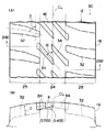
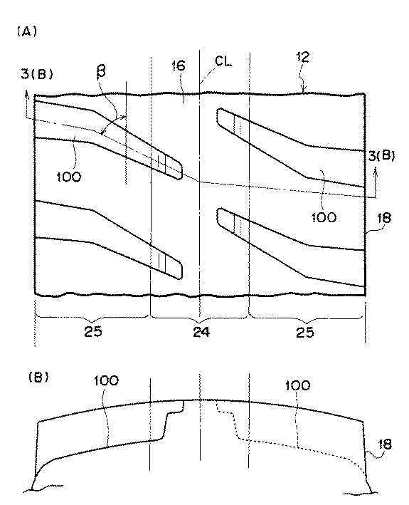
従来例:図3(A),(B)に示すように、センター領域24内まで延びる主ラグ溝100により形成されたラグパターンを有する空気入りタイヤである。
【0064】
なお、試験タイヤのその他の諸元は以下の表1内に記載されている通りである。
【0065】
発熱試験:供試タイヤを正規リム(13.00/2.5)に正規内圧(700kPa)でリム組みし、正規荷重(14000kg)を付加して速度10km/hで、室内ドラム試験機によって一定時間走行後のトレッドのセンター領域の温度を測定した。
【0066】
なお、発熱試験の試験結果は、従来例のタイヤの温度の逆数を100とする指数で表しており、数値の大きいものほど温度上昇が少なく、トレッドの耐久性(発熱耐久性)に優れていることを示す。
【0067】
摩耗試験:供試タイヤを正規リム(13.00/2.5)に正規内圧(700kPa)でリム組みし、正規荷重(14000kg)を付加して速度10km/hで、室内ドラム試験機によって一定時間走行後のトレッドの摩耗量を測定した。
【0068】
なお、摩耗試験の試験結果は、従来例のタイヤの摩耗量の逆数を100とする指数で表しており、数値の大きいものほど摩耗が少なく、耐摩耗性能に優れていることを示す。
【0069】
【表1】
試験の結果、本発明の適用された実施例1及び実施例2のタイヤは、従来例のタイヤに比較して転動時のセンター領域の温度上昇が少なく、このことからトレッドの発熱耐久性に優れていることは明らかである。
【0071】
また、本発明の適用された実施例1及び実施例2のタイヤは、従来例のタイヤと同等の耐摩耗性を有していた。
【0072】
【発明の効果】
以上説明したように、本発明の空気入りタイヤは上記の構成としたので、トレッドの耐摩耗性を損なうこと無く、トレッドのクラウン部の耐久性を向上することができる、という優れた効果を有する。
【図面の簡単な説明】
【図1】(A)は本発明の第1の実施形態に係る空気入りタイヤのトレッドの平面図であり、(B)は図1(A)に示すトレッドの1(B)−1(B)線断面図である。
【図2】(A)は本発明の第2の実施形態に係る空気入りタイヤのトレッドの平面図であり、(B)は図2(A)に示すトレッドの2(B)−2(B)線断面図である。
【図3】(A)は従来例に係る空気入りタイヤのトレッドの平面図であり、(B)は図3(A)に示すトレッドの3(B)−3(B)線断面図である。
【符号の説明】
10 空気入りタイヤ
12 主ラグ溝
16 陸部
20 主ラグ溝
22 補助ラグ溝
24 センター領域
30 タイヤ赤道面
32 主ラグ溝
34 補助ラグ溝[0001]
BACKGROUND OF THE INVENTION
The present invention relates to a pneumatic tire, and in particular, to provide a pneumatic tire having a lug pattern that can improve the durability of a crown portion used in a heavy load vehicle mounted on a construction vehicle or the like. is there.
[0002]
[Prior art]
In a pneumatic tire used for a construction vehicle, a lag groove pattern having a land portion substantially continuous in a tire circumferential direction at a tire center portion is a mainstream.
[0003]
In such a lug groove pattern, the heat dissipation effect at the tire center portion is small, the tire center portion is high, and the shoulder portion has a low temperature distribution.
[0004]
[Problems to be solved by the invention]
In order to improve the durability of the crown part, it is effective to reduce the temperature of the crown part, that is, to suppress the temperature rise due to running. Conventionally, a tread compound with low heat generation is used as the technique. Or tread volume reduction (groove depth reduction, negative ratio reduction) and the like.
[0005]
However, the conventional technique has a trade-off characteristic that the durability (heat separation resistance, cut separation resistance) of the crown portion is improved in any case, but the wear resistance of the tread is reduced.
[0006]
In view of the above facts, an object of the present invention is to provide a pneumatic tire having a lug groove pattern that can improve the durability of the crown portion of the tread without impairing the wear resistance of the tread.
[0007]
[Means for Solving the Problems]
The invention according to
[0008]
Next, the operation of the pneumatic tire according to
[0009]
The temperature of the tread portion is determined by heat generation due to repeated deformation (compression and bending) during rolling of the tire and the amount of heat released from the surface of the tire pattern.
[0010]
In the pneumatic tire according to
[0011]
If the groove area of the center region is simply increased, the lug rigidity of the center region is reduced and the wear resistance is lowered, but by gradually decreasing the groove depth of the auxiliary lug groove toward the tire equatorial plane. A decrease in rigidity can be suppressed, and wear resistance is ensured.
In the pneumatic tire according to
[0012]
Pneumatic tires are used by attaching to standard rims defined by standards issued by JATMA (Japan), TRA (US), ETRTO (Europe), etc., depending on the size. Usually called a regular rim.
[0013]
In accordance with this common designation herein, “regular rim” refers to a standard rim in the applicable size defined in the 1998 YEAR BOOK issued by the United States Tire and Rim Association TRA.
[0014]
Similarly, “regular load” and “regular internal pressure” are the air pressure corresponding to the maximum load and the maximum load in the applicable size / ply rating defined in the 1998 YEAR BOOK issued by the United States Tire and Rim Association TRA. Point to.
[0015]
Also, in this specification, “tire maximum contact width” means a tire of a tread when a tire is assembled to a “regular rim” and filled with “regular internal pressure” and a “regular load” is statically applied. The maximum ground contact width in the axial direction.
[0016]
Here, the load is the maximum load (maximum load capacity) of a single wheel at the applicable size described in the following standard, and the internal pressure is the maximum load of a single wheel at the applicable size described in the following standard ( The rim is a standard rim (or “Approved Rim”, “Recommended Rim”) in the applicable size described in the following standards.
[0017]
The standard is determined by an industrial standard effective in the region where the tire is produced or used. For example, “Year Book of The Tire and Rim Association Inc.” in the United States, “Standards Manual of The European Tire and Rim Technical Organization” in Europe, and “JATMA Year Book” of the Japan Automobile Tire Association in Japan. It is prescribed.
[0018]
The invention according to
[0019]
The temperature of the tread portion is determined by heat generation due to repeated deformation (compression and bending) during rolling of the tire and the amount of heat released from the surface of the tire pattern.
[0020]
In the pneumatic tire according to
[0021]
If the groove area of the center region is simply increased, the lug rigidity of the center region is reduced and the wear resistance is lowered, but by gradually decreasing the groove depth of the auxiliary lug groove toward the tire equatorial plane. A decrease in rigidity can be suppressed, and wear resistance is ensured.
[0022]
Moreover, it is preferable to arrange | position the auxiliary | assistant lug groove provided independently of the main lug groove between the main lug grooves arrange | positioned at intervals in the circumferential direction.
[0023]
In the pneumatic tire according to
[0024]
Next, the operation of the pneumatic tire according to
[0025]
Since the groove depth of the auxiliary lug groove is set to 45 to 70% of the maximum depth of the main lug groove, the rigidity of the center region can be ensured while obtaining the temperature rise suppressing effect of the center region.
[0026]
If the groove depth of the auxiliary lug groove is less than 45% of the maximum depth of the main lug groove, the temperature rise suppressing effect is insufficient, and the groove depth of the auxiliary lug groove is 70% of the maximum depth of the main lug groove. Beyond this, the rigidity of the center area is insufficient.
[0031]
DETAILED DESCRIPTION OF THE INVENTION
[First Embodiment]
1st Embodiment of the pneumatic tire of this invention is described according to FIG. 1 (A), (B).
[0032]
As shown in FIGS. 1A and 1B, the
[0033]
Here, in the
[0034]
The negative rate of the
[0035]
The
[0036]
The
[0037]
The
[0038]
In addition, since the internal structure of the
[0039]
Next, the effect | action of the
[0040]
When the
[0041]
In the present embodiment, since the groove depth d of the
[0042]
Further, since the groove depth d of the
[0043]
Note that when the groove depth d of the
[0044]
Moreover, since the angle α formed by the groove width center line GL of the
[0045]
When the angle α exceeds 55 °, the length of the
[Second Embodiment]
A second embodiment of the pneumatic tire of the present invention will be described with reference to FIGS. In addition, the same code | symbol is attached | subjected about the same structure as 1st Embodiment, and the description is abbreviate | omitted.
[0046]
As shown in FIGS. 2A and 2B, the
[0047]
The
[0048]
The
[0049]
The negative rate of the
[0050]
The
[0051]
The
[0052]
The
[0053]
Next, the effect | action of the
[0054]
When the
[0055]
In the present embodiment, since the groove depth d of the
[0056]
Further, since the groove depth d of the
[0057]
When the groove depth d of the
[0058]
In addition, since the angle α formed by the groove width center line GL of the
[0059]
When the angle α exceeds 55 °, the length of the
[0060]
In the present embodiment, the
(Test example)
In order to confirm the effect of the present invention, two types of tires according to the examples to which the present invention is applied and one type of conventional tire (both tire sizes are ORR18.00R25) are prepared, and an exothermic test is performed by an indoor drum tester. A wear test was conducted.
[0061]
Example 1: A pneumatic tire having the lug pattern shown in FIG.
[0062]
Example 2: A pneumatic tire having the lug pattern shown in FIG.
[0063]
Conventional Example: As shown in FIGS. 3A and 3B, a pneumatic tire having a lug pattern formed by a
[0064]
The other specifications of the test tire are as described in Table 1 below.
[0065]
Heat generation test: The test tire is assembled to a regular rim (13.00 / 2.5) at a regular internal pressure (700 kPa), a regular load (14000 kg) is applied, and the speed is 10 km / h, constant by an indoor drum tester. The temperature in the center area of the tread after running for a time was measured.
[0066]
In addition, the test result of the exothermic test is represented by an index with the reciprocal of the temperature of the tire of the conventional example being 100, and the higher the numerical value, the less the temperature rises and the better the tread durability (exothermic durability). It shows that.
[0067]
Abrasion test: A test tire is assembled to a regular rim (13.00 / 2.5) at a regular internal pressure (700 kPa), a regular load (14000 kg) is applied, and the speed is 10 km / h, constant by an indoor drum tester. The amount of wear on the tread after running for an hour was measured.
[0068]
In addition, the test result of the wear test is represented by an index in which the reciprocal of the wear amount of the tire of the conventional example is 100, and the larger the value, the less the wear and the better the wear resistance performance.
[0069]
[Table 1]
As a result of the test, the tires of Example 1 and Example 2 to which the present invention is applied have less temperature rise in the center region at the time of rolling compared to the tires of the conventional example, and thus the heat generation durability of the tread is improved. It is clear that it is excellent.
[0071]
Further, the tires of Example 1 and Example 2 to which the present invention was applied had wear resistance equivalent to that of the conventional tire.
[0072]
【The invention's effect】
As described above, since the pneumatic tire of the present invention has the above-described configuration, it has an excellent effect that the durability of the crown portion of the tread can be improved without impairing the wear resistance of the tread. .
[Brief description of the drawings]
FIG. 1A is a plan view of a tread of a pneumatic tire according to a first embodiment of the present invention, and FIG. 1B is a view of 1 (B) -1 (B of the tread shown in FIG. FIG.
2A is a plan view of a tread of a pneumatic tire according to a second embodiment of the present invention, and FIG. 2B is a view of a tread 2 (B) -2 (B FIG.
3A is a plan view of a tread of a pneumatic tire according to a conventional example, and FIG. 3B is a cross-sectional view taken along the line 3 (B) -3 (B) of the tread shown in FIG. 3A. .
[Explanation of symbols]
DESCRIPTION OF
Claims (3)
タイヤ接地最大幅の30%以内に対応するセンター領域に、溝深さがタイヤ赤道面に向かって漸減する補助ラグ溝を前記主ラグ溝に延長して設け、
前記センター領域のネガティブ率を10〜35%とし、
前記補助ラグ溝の前記センター領域の幅方向端部からタイヤ赤道面に向かう溝幅中心線のタイヤ赤道面となす角度を40〜55°とした、空気入りタイヤ。A pneumatic tire having a plurality of main lug grooves extending in the tire circumferential direction from the shoulder side toward the tire equatorial plane and having a lug pattern having a land portion extending substantially continuously in the tire circumferential direction in the tread central region In
In the center region corresponding to within 30% of the maximum tire ground contact width, an auxiliary lug groove whose groove depth gradually decreases toward the tire equatorial plane is provided extending to the main lug groove,
The negative rate of the center region is 10 to 35% ,
A pneumatic tire having an angle of 40 to 55 ° with a tire equator plane of a groove width center line from a width direction end portion of the center region of the auxiliary lug groove toward the tire equator plane .
タイヤ接地最大幅の30%以内に対応するセンター領域に、溝深さがタイヤ赤道面に向かって漸減する補助ラグ溝を、前記主ラグ溝とは独立して設け、
前記センター領域のネガティブ率を10〜35%としたことを特徴とする空気入りタイヤ。A pneumatic tire having a plurality of main lug grooves extending in the tire circumferential direction from the shoulder side toward the tire equatorial plane and having a lug pattern having a land portion extending substantially continuously in the tire circumferential direction in the tread central region In
An auxiliary lug groove whose groove depth gradually decreases toward the tire equatorial plane is provided independently of the main lug groove in the center region corresponding to within 30% of the tire ground contact maximum width,
A pneumatic tire characterized by having a negative rate of 10 to 35% in the center region.
Priority Applications (1)
| Application Number | Priority Date | Filing Date | Title |
|---|---|---|---|
| JP07353499A JP4227239B2 (en) | 1999-03-18 | 1999-03-18 | Pneumatic tire |
Applications Claiming Priority (1)
| Application Number | Priority Date | Filing Date | Title |
|---|---|---|---|
| JP07353499A JP4227239B2 (en) | 1999-03-18 | 1999-03-18 | Pneumatic tire |
Publications (2)
| Publication Number | Publication Date |
|---|---|
| JP2000264022A JP2000264022A (en) | 2000-09-26 |
| JP4227239B2 true JP4227239B2 (en) | 2009-02-18 |
Family
ID=13521003
Family Applications (1)
| Application Number | Title | Priority Date | Filing Date |
|---|---|---|---|
| JP07353499A Expired - Fee Related JP4227239B2 (en) | 1999-03-18 | 1999-03-18 | Pneumatic tire |
Country Status (1)
| Country | Link |
|---|---|
| JP (1) | JP4227239B2 (en) |
Cited By (1)
| Publication number | Priority date | Publication date | Assignee | Title |
|---|---|---|---|---|
| CN102639340A (en) * | 2009-12-04 | 2012-08-15 | 株式会社普利司通 | Pneumatic tire for motorcycle |
Families Citing this family (9)
| Publication number | Priority date | Publication date | Assignee | Title |
|---|---|---|---|---|
| JP4955860B2 (en) * | 2001-04-09 | 2012-06-20 | 住友ゴム工業株式会社 | Pneumatic tire |
| JP4602782B2 (en) | 2005-02-03 | 2010-12-22 | 株式会社ブリヂストン | Heavy duty pneumatic tire |
| JP5727502B2 (en) * | 2010-10-22 | 2015-06-03 | 株式会社ブリヂストン | Heavy duty pneumatic tires for construction vehicles |
| EP2754567B1 (en) * | 2011-09-09 | 2017-05-10 | Bridgestone Corporation | Pneumatic tire |
| JP5977696B2 (en) | 2013-03-13 | 2016-08-24 | 株式会社ブリヂストン | Pneumatic tire |
| JP5799043B2 (en) | 2013-03-13 | 2015-10-21 | 株式会社ブリヂストン | Pneumatic tire |
| JP5785577B2 (en) * | 2013-03-13 | 2015-09-30 | 株式会社ブリヂストン | Pneumatic tire |
| JP6060138B2 (en) * | 2014-12-02 | 2017-01-11 | 株式会社ブリヂストン | Pneumatic tire |
| JP5985005B2 (en) * | 2015-05-25 | 2016-09-06 | 株式会社ブリヂストン | Pneumatic tire |
-
1999
- 1999-03-18 JP JP07353499A patent/JP4227239B2/en not_active Expired - Fee Related
Cited By (1)
| Publication number | Priority date | Publication date | Assignee | Title |
|---|---|---|---|---|
| CN102639340A (en) * | 2009-12-04 | 2012-08-15 | 株式会社普利司通 | Pneumatic tire for motorcycle |
Also Published As
| Publication number | Publication date |
|---|---|
| JP2000264022A (en) | 2000-09-26 |
Similar Documents
| Publication | Publication Date | Title |
|---|---|---|
| JP4776622B2 (en) | Construction vehicle tires | |
| US10399390B2 (en) | Pneumatic tire | |
| EP3088213B1 (en) | Pneumatic tire | |
| JP5275610B2 (en) | Pneumatic tire | |
| WO2009096133A1 (en) | Pneumatic tire | |
| JP4539774B2 (en) | Heavy duty pneumatic tire | |
| EP1498288A1 (en) | Pneumatic tire | |
| JP4015623B2 (en) | Heavy duty tire | |
| JP4180910B2 (en) | Heavy duty radial tire | |
| JP4227239B2 (en) | Pneumatic tire | |
| JP5109823B2 (en) | Pneumatic tire | |
| JPWO2009048078A1 (en) | tire | |
| CN106427402B (en) | Pneumatic tire | |
| JP4303343B2 (en) | Pneumatic tire | |
| JP4170066B2 (en) | Pneumatic tire | |
| JP4915069B2 (en) | Pneumatic tire | |
| JP4687342B2 (en) | Pneumatic tire | |
| JP4608111B2 (en) | Pneumatic tires for construction vehicles | |
| JP6658934B2 (en) | Heavy duty tire | |
| JP4285617B2 (en) | Pneumatic radial tire | |
| JP4872066B2 (en) | Pneumatic tire | |
| JP3967917B2 (en) | Pneumatic tire | |
| US20210379935A1 (en) | Pneumatic Tire | |
| JP3513340B2 (en) | Pneumatic tires for vehicles | |
| JPWO2006001290A1 (en) | Pneumatic tire |
Legal Events
| Date | Code | Title | Description |
|---|---|---|---|
| A621 | Written request for application examination |
Free format text: JAPANESE INTERMEDIATE CODE: A621 Effective date: 20051220 |
|
| A977 | Report on retrieval |
Free format text: JAPANESE INTERMEDIATE CODE: A971007 Effective date: 20080814 |
|
| A131 | Notification of reasons for refusal |
Free format text: JAPANESE INTERMEDIATE CODE: A131 Effective date: 20080819 |
|
| A521 | Written amendment |
Free format text: JAPANESE INTERMEDIATE CODE: A523 Effective date: 20081017 |
|
| TRDD | Decision of grant or rejection written | ||
| A01 | Written decision to grant a patent or to grant a registration (utility model) |
Free format text: JAPANESE INTERMEDIATE CODE: A01 Effective date: 20081125 |
|
| A01 | Written decision to grant a patent or to grant a registration (utility model) |
Free format text: JAPANESE INTERMEDIATE CODE: A01 |
|
| A61 | First payment of annual fees (during grant procedure) |
Free format text: JAPANESE INTERMEDIATE CODE: A61 Effective date: 20081128 |
|
| FPAY | Renewal fee payment (event date is renewal date of database) |
Free format text: PAYMENT UNTIL: 20111205 Year of fee payment: 3 |
|
| R150 | Certificate of patent or registration of utility model |
Free format text: JAPANESE INTERMEDIATE CODE: R150 |
|
| FPAY | Renewal fee payment (event date is renewal date of database) |
Free format text: PAYMENT UNTIL: 20111205 Year of fee payment: 3 |
|
| FPAY | Renewal fee payment (event date is renewal date of database) |
Free format text: PAYMENT UNTIL: 20121205 Year of fee payment: 4 |
|
| FPAY | Renewal fee payment (event date is renewal date of database) |
Free format text: PAYMENT UNTIL: 20121205 Year of fee payment: 4 |
|
| FPAY | Renewal fee payment (event date is renewal date of database) |
Free format text: PAYMENT UNTIL: 20131205 Year of fee payment: 5 |
|
| R250 | Receipt of annual fees |
Free format text: JAPANESE INTERMEDIATE CODE: R250 |
|
| R250 | Receipt of annual fees |
Free format text: JAPANESE INTERMEDIATE CODE: R250 |
|
| R250 | Receipt of annual fees |
Free format text: JAPANESE INTERMEDIATE CODE: R250 |
|
| R250 | Receipt of annual fees |
Free format text: JAPANESE INTERMEDIATE CODE: R250 |
|
| LAPS | Cancellation because of no payment of annual fees |