JP4222686B2 - Tunnel excavation method and beam columns - Google Patents
Tunnel excavation method and beam columns Download PDFInfo
- Publication number
- JP4222686B2 JP4222686B2 JP16509599A JP16509599A JP4222686B2 JP 4222686 B2 JP4222686 B2 JP 4222686B2 JP 16509599 A JP16509599 A JP 16509599A JP 16509599 A JP16509599 A JP 16509599A JP 4222686 B2 JP4222686 B2 JP 4222686B2
- Authority
- JP
- Japan
- Prior art keywords
- beam column
- connection
- main body
- column
- fitting portion
- Prior art date
- Legal status (The legal status is an assumption and is not a legal conclusion. Google has not performed a legal analysis and makes no representation as to the accuracy of the status listed.)
- Expired - Lifetime
Links
Images
Landscapes
- Excavating Of Shafts Or Tunnels (AREA)
Description
【0001】
【発明の属する技術分野】
本発明は軌道、道路、地下埋設物直下等の比較的短いトンネルを掘削施工するトンネルの掘削施工工法および梁柱に関する。
【0002】
【従来の技術】
従来、この種のトンネルの掘削施工工法としてパイプルーフ工法、パイプビーム工法、URT工法、PCR工法、NNCB工法等が行なわれている。
【0003】
【発明が解決しようとする課題】
従来のパイプルーフ工法はパイプは仮設材であり、土留の役目しかしないとともに、パイプの径の分土被りが深く必要であるという欠点がある。
また、パイプビーム工法はパイプは仮設材であり、土留の役目しかしないとともに、両側に大きな仮受け梁が深く必要であるという欠点がある。
さらに、URT工法、PCR工法、NNCB工法はいずれも両側に大きな仮受け梁が必要であるという欠点がある。
【0004】
本発明は以上のような従来の欠点に鑑み、大規模設備を用いることなく、安全で経済的に品質が一定である梁柱を用いてトンネルの掘削施工を行なうことができるとともに、トンネルの形状を自由に形成することができるトンネルの掘削施工工法および梁柱を提供することを目的としている。
【0005】
本発明の前記ならびにそのほかの目的と新規な特徴は次の説明を添付図面と照らし合わせて読むと、より完全に明らかになるであろう。
ただし、図面はもっぱら解説のためのものであって、本発明の技術的範囲を限定するものではない。
【0006】
【課題を解決するための手段】
上記目的を達成するために、本発明はトンネルの施工箇所の一側面より梁柱挿入孔を掘削しながら該梁柱挿入孔に継手鋼管を順次押し込み、他側面まで掘削する掘削工程、この掘削工程後に梁柱挿入孔に挿入された継手鋼管を押し込み排出させながら推進方向および接続方向に嵌合する嵌合部が形成された複数本の梁柱を順次挿入させる梁柱挿入工程とで梁柱を設置する梁柱設置工程と、この梁柱設置工程で設置された梁柱の側面部位のトンネル施工箇所の一側面あるいは他側面より接続用梁柱挿入孔を掘削しながら該接続用梁柱挿入孔に継手鋼管を順次挿入して他側面あるいは一側面まで掘削する接続用掘削工程、この接続用掘削工程後に接続用梁柱挿入孔に挿入された継手鋼管を押し込み排出させながら推進方向および接続方向に嵌合する嵌合部が形成された複数本の接続用梁柱および端部に端部接続用梁柱が位置するように前記梁柱と嵌合させながら順次挿入させる接続梁柱挿入工程とで接続梁柱を設置する接続梁柱設置工程と、この接続梁柱設置工程で設置された接続梁柱の側面部位に該接続梁柱設置工程と同様な作業を順次行なって多数本の接続梁柱を並列状態で設置するトンネルの上部あるいは下部壁本体の設置工程と、この上部あるいは下部壁本体の設置工程で設置された上部あるいは下部壁本体の両端部の梁柱および接続梁柱の下面あるいは上面に前記接続梁柱設置工程と同様な作業を順次行なって両側壁本体を設置する両側壁本体設置工程と、この両側壁本体設置工程で設置された両側壁本体の端部の接続梁柱の内側面に前記接続梁柱設置工程と同様な作業を順次行なって下部あるいは上部壁本体を設置する、下部あるいは上部壁本体設置工程と、この下部あるいは上部壁本体設置工程後に上下壁本体および両側壁本体内の土砂を掘削除去しながら所定間隔に支保工を配置する支保工配置工程とでトンネルの掘削施工工法を構成している。
【0007】
また、本発明は角柱状の梁柱本体と、この梁柱本体の一端部に形成された突部状の嵌合部と、前記梁柱本体の他端部に形成された接続される梁柱本体の突部状の嵌合部が嵌合される凹部状の嵌合部と、前記梁柱本体の両側面のほぼ中央部に形成された凹部溝状あるいは突部状の嵌合部とで梁柱を構成している。
【0008】
【発明の実施の形態】
以下、図面に示す実施の形態により、本発明を詳細に説明する。
【0009】
図1ないし図21に示す本発明の第1の実施の形態において、1は軌道2の直下のトンネル施工箇所3に梁柱4を設置する梁柱設置工程で、この梁柱設置工程1はトンネル施工箇所3の一側面より推進掘削装置5を用いて梁柱挿入孔6を掘削しながら、該梁柱挿入孔6に継手鋼管7を順次押し込み、他側面まで掘削する掘削工程8と、この掘削工程8後に梁柱挿入孔6に挿入された継手鋼管7を押し込み排出させながら推進方向および接続方向に嵌合する嵌合部が形成された複数本の梁柱4を順次挿入させた後、該複数本の梁柱4を超強度棒鋼等の棒鋼9で固定する梁柱挿入工程10とで構成されている。
【0010】
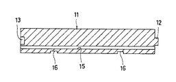
前記梁柱4は図3および図4に示すように、角柱状に形成された梁柱本体11と、この梁柱本体11の一端部の中央部に形成された突部状の嵌合部12と、前記梁柱本体11の他端部の中央部に形成された接続される梁柱4の突部状の嵌合部12が嵌合される凹部状の嵌合部13と、前記梁柱本体11の両側面のほぼ中央部に形成された凹部溝状の嵌合部14、14と、前記梁柱本体11のほぼ中央内側寄りの部位に形成された超強度棒鋼等を挿入することができる棒鋼等の挿入孔15と、前記梁柱本体11の内側となる側面の全長の4分の1部位に形成された支保工挿入凹部16、16とで構成されたものを複数個直列接続されて構成されている。
なお、前記梁柱4は棒鋼等の挿入孔15に超強度棒鋼等を挿入して使用する場合には梁柱本体11の一端部と他端部の中央部に形成する突部状の嵌合部12と凹部状の嵌合部13のない梁柱本体11を使用してもよい。
【0011】
17は前記梁柱設置工程1で設置された梁柱4の側面部位のトンネル施工箇所3に接続梁柱18を設置する接続梁柱設置工程で、この接続梁柱設置工程17は前記梁柱4の側面部位のトンネル施工箇所3の一側面あるいは他側面より接続用梁柱挿入孔19を推進掘削装置5を用いて掘削しながら該接続用梁柱挿入孔19に継手鋼管7を順次挿入して他側面あるいは一側面まで掘削する接続用掘削工程20と、この接続用掘削工程20後に接続用梁柱挿入孔19に挿入された継手鋼管7を押し込み排出させながら推進方向および接続方向に嵌合する嵌合部が形成された複数本の接続用梁柱21を、前記梁柱4と嵌合させながら順次挿入させた後、該複数本の接続用梁柱21を超強度棒鋼等の棒鋼9で固定して接続梁柱18を形成する接続梁柱挿入工程22とで構成されている。
【0012】
前記接続用梁柱21は図6および図7に示すように、角柱状に形成された接続用梁柱本体23と、この接続用梁柱本体23の一端部の中央部に形成された突部状の嵌合部12と、前記接続用梁柱本体23の他端部の中央部に形成された接続される接続梁柱18の突部状の嵌合部12が嵌合される凹部状の嵌合部13と、前記接続用梁柱本体23の一側面に形成された前記梁柱4の凹部溝状の嵌合部14と嵌合される突部状の嵌合部24と、この突部状の嵌合部24と対応する前記接続用梁柱本体23の他側面に形成された接続される接続梁柱18の突部状の嵌合部24が嵌合される凹部溝状の嵌合部14と、前記接続用梁柱本体23のほぼ中央内側寄りの部位に形成された超強度棒鋼等を挿入することができる棒鋼等の挿入孔15と、前記接続用梁柱本体23の内側となる側面の全長の4分の1部位に形成された支保工挿入凹部16、16とで構成されたものを複数個直列接続されて構成されている。
なお、前記接続用梁柱21は棒鋼等の挿入孔15に超強度棒鋼等を挿入して使用する場合には、接続用梁柱本体23の一端部と他端部の中央部に形成する突部状の嵌合部12と凹部状の嵌合部13のない接続用梁柱本体23を使用してもよい。
【0013】
なお、この接続梁柱設置工程17で梁柱4に嵌合状態で設置される接続梁柱18は、図8に示すように該接続梁柱18の接続用梁柱21の接続部が梁柱4の接続部のほぼ中央部に位置させるように設置することにより、梁柱4と接続梁柱18の支保工挿入凹部16、16部位が一致する。
【0014】
25は前記接続梁柱設置工程17で設置された接続梁柱18と前記梁柱設置工程1で設置された梁柱4の両側部に該接続梁柱設置工程17と同様な作業を順次行なって多数本の接続梁柱18を並列状態で設置するトンネルの上部壁本体26を設置する上部壁本体設置工程で、この上部壁本体設置工程25で設置する上部壁本体26の両端部には端部接続梁柱27、27が設置される。
【0015】
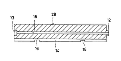
この端部接続梁柱27、27は図11および図12に示すように、角柱状に形成された端部接続用梁柱本体28と、この端部接続用梁柱本体28の一端部の中央部に形成された突部状の嵌合部12と、前記端部接続用梁柱本体28の他端部の中央部に形成された接続される端部接続用梁柱本体28の突部状の嵌合部12と嵌合する凹部状の嵌合部13と、前記端部接続用梁柱本体28の一側面の中央部に形成され接続される接続用梁柱21の凹部溝状の嵌合部14と嵌合する突部状の嵌合部24と、この突部状の嵌合部24と隣り合う一方の面の中央部に形成された接続される接続用梁柱21の突部状の嵌合部24と嵌合する凹部溝状の嵌合部14と、前記端部接続用梁柱本体28のほぼ中央部に形成された超強度棒鋼等を挿入することができる棒鋼等の挿入孔15と、前記端部接続用梁柱本体28の突部状の嵌合部24と凹部溝状の嵌合部14が形成された部位で該端部接続用梁柱本体28の全長の4分の1部位に形成された支保工挿入凹部16、16とで構成されたものを複数個直列接続されて構成されている。
なお、前記端部接続梁柱27は棒鋼等の挿入孔15に超強度棒鋼等を挿入して使用する場合には、端部接続用梁柱本体28の一端部と他端部の中央部に形成する突部状の嵌合部12と凹部状の嵌合部13のない端部接続用梁柱本体28を使用してもよい。
【0016】
29は前記上部壁本体設置工程25で設置された上部壁本体26の両端部の端部接続梁柱27、27に前記接続梁柱設置工程17と同様な作業を順次行なって両側壁本体30、30を設置する両側壁本体設置工程で、この両側壁本体設置工程29でも最下部位置には端部接続梁柱27、27を設置する。
【0017】
31は前記両側壁本体設置工程29で設置された両側壁本体30、30の最下部の端部接続梁柱27、27の内側面に前記接続梁柱設置工程17と同様な作業を順次行なって下部壁本体32を設置する下部壁本体設置工程である。
なお、この下部壁本体32を設置する場合には中間部に図17および図18に示すような両側面に突部状の嵌合部24、24が形成された中間接続用梁柱本体42を接続させた中間接続用梁柱41を用いる。
この中間接続用梁柱41は棒鋼等の挿入孔15に超強度棒鋼等を挿入して使用する場合には、中間接続用梁柱本体42の一端部と他端部の中央部に形成する突部状の嵌合部12と凹部状の嵌合部13のない中間接続用梁柱本体42を使用してもよい。
【0018】
33は前記下部壁本体設置工程31後に上下部壁本体26、32および両側壁本体30、30内の土砂34を掘削除去しながら梁柱4、接続梁柱18、端部接続梁柱27の支保工挿入凹部16、16、16が露出した部分に鋼材製の支保工35を順次配置してトンネル孔36を形成する支保工配設工程である。
【0019】
37は前記支保工配設工程33後に下部壁本体32、両側壁本体30、30、上部壁本体26の内側に型枠等を用いて壁コンクリート38を打設する壁コンクリート打設工程である。
【0020】
上記のような各工程を行なうトンネルの掘削施工工法でトンネル39を形成することにより、安全で経済的にトンネル39を形成することができる。
【0021】
【発明の異なる実施の形態】
次に、図22ないし図30に示す本発明の異なる実施の形態につき説明する。なお、これらの本発明の異なる実施の形態の説明に当って、前記本発明の第1の実施の形態と同一構成部分には同一符号を付して重複する説明を省略する。
【0022】
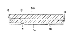
図22ないし図27に示す本発明の第2の実施の形態において、前記本発明の第1の実施の形態と主に異なる点は、トンネルの施工箇所3の一方の上部角部に図26および図27に示す端部接続用梁柱本体28Aを用いて端部接続梁柱27Aを設置する梁柱設置工程1Aを行ない、この梁柱設置工程1A後に接続梁柱設置工程17、上部壁本体設置工程25、両側壁本体設置工程29、29を順次行なった点で、このような方法を用いたトンネルの掘削施工工法を行なっても、前記本発明の第1の実施の形態と同様な作用効果が得られる。
なお、部接続梁柱27Aは棒鋼等の挿入孔15に超強度棒鋼等を挿入して使用する場合には、端部接続用梁柱本体28Aの一端部と他端部の中央部に形成する突部状の嵌合部12と凹部状の嵌合部13のない端部接続用梁柱本体28Aを使用してもよい。
【0023】
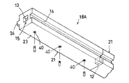
図28ないし図30に示す本発明の第3の実施の形態において、前記本発明の第1の実施の形態と主に異なる点は、梁柱設置工程1Bおよび接続梁柱設置工程17Aで、図29および図30に示すように所定間隔にジベルを取付けるための雌ねじ40を埋設した梁柱4Aおよび接続梁柱18Aを用いた点で、このような梁柱4Aや接続梁柱18Aを用いて梁柱設置工程1Bや接続梁柱設置工程17Aを行なってトンネルの掘削施工工法を行なっても、前記本発明の第1の実施の形態と同様な作用効果が得られる。
【0024】
なお、前記本発明の各実施の形態では、上部壁本体26、両側壁本体30、30、下部壁本体32を順次形成するものについて説明したが、本発明はこれに限らず、下部壁本体32、両側壁本体30、30、上部壁本体26を順次形成してもよく、また、一方の側壁本体30、上部壁本体26、下部壁本体32、他方の側壁本体30を順次形成してもよい。
なお、最初に形成する上部壁本体26あるいは下部壁本体32は中央部から形成したり、一端部から形成するが、この場合、最初に形成する梁柱は突部状の嵌合部のない梁柱本体11、端部接続用梁柱本体28Aを用いて行う。
また、上部壁本体26、両側壁本体30、30、下部壁本体32を効率よく形成するために、推進掘削装置5を2台以上用いて行なってもよい。
さらに、トンネルの施工箇所の両側面に推進掘削装置5を設置する発進立杭、到達立杭の掘削作業を梁柱設置工程1、1A前に行なったり、トンネル施工箇所に薬液注入して地盤改良を行なう作業を必要に応じて行なう。
なお、前記本発明の各実施の形態では梁柱4、4Aを構成する梁柱本体11、接続梁柱18、18Aを構成する接続用梁柱21、端部接続梁柱27、27Aを構成する端部接続用梁柱本体28、28Aおよび中間接続用梁柱41を構成する中間接続用梁柱42の一端部と他端部の中央部に形成する突部状の嵌合部12と凹部状の嵌合部13は図示以外の同半径寸法の弧状の突部状の嵌合部12と凹部状の嵌合部13や異なる半径寸法の弧状の突部状の嵌合部12と凹部状の嵌合部13であつもよく、その他の形状の突部状の嵌合部12と凹部状の嵌合部13であつてもよい。さらにT字状の嵌合部12と、このT字状の嵌合部12と側面からの押し込みによって嵌合するT字状の溝が形成された凹部状の嵌合部13であつてもよい。
【0025】
【発明の効果】
以上の説明から明らかなように、本発明にあっては次に列挙する効果が得られる。
【0026】
(1)トンネルの施工箇所の一側面より梁柱挿入孔を掘削しながら該梁柱挿入孔に継手鋼管を順次押し込み、他側面まで掘削する掘削工程、この掘削工程後に梁柱挿入孔に挿入された継手鋼管を押し込み排出させながら推進方向および接続方向に嵌合する嵌合部が形成された複数本の梁柱を順次挿入させる梁柱挿入工程とで梁柱を設置する梁柱設置工程と、この梁柱設置工程で設置された梁柱の側面部位のトンネル施工箇所の一側面あるいは他側面より接続用梁柱挿入孔を掘削しながら該接続用梁柱挿入孔に継手鋼管を順次挿入して他側面あるいは一側面まで掘削する接続用掘削工程、この接続用掘削工程後に接続用梁柱挿入孔に挿入された継手鋼管を押し込み排出させながら推進方向および接続方向に嵌合する嵌合部が形成された複数本の接続用梁柱および端部に端部接続用梁柱が位置するように前記梁柱と嵌合させながら順次挿入させる接続梁柱挿入工程とで接続梁柱を設置する接続梁柱設置工程と、この接続梁柱設置工程で設置された接続梁柱の側面部位に該接続梁柱設置工程と同様な作業を順次行なって多数本の接続梁柱を並列状態で設置するトンネルの上部あるいは下部壁本体の設置工程と、この上部あるいは下部壁本体の設置工程で設置された上部あるいは下部壁本体の両端部の梁柱および接続梁柱の下面あるいは上面に前記接続梁柱設置工程と同様な作業を順次行なって両側壁本体を設置する両側壁本体設置工程と、この両側壁本体設置工程で設置された両側壁本体の端部の接続梁柱の内側面に前記接続梁柱設置工程と同様な作業を順次行なって下部あるいは上部壁本体を設置する下部あるいは上部壁本体設置工程と、この下部あるいは上部壁本体設置工程後に上下部壁本体および両側壁本体内の土砂を掘削除去しながら所定間隔に支保工を配置する支保工配置工程とからなるので、上部壁本体、両側壁本体および下部壁本体を構成する梁柱が左右方向に嵌合部によって嵌合接続された状態にできる。
したがって、十分な強度が得られる上部壁本体、両側壁本体、下部壁本体を設置することができる。
【0027】
(2)前記(1)によって、上部壁本体、両側壁本体、下部壁本体を設置した後、内部の土砂を掘削するので、安全に掘削作業を行なうことができる。
【0028】
(3)前記(1)によって、上部壁本体、両側壁本体および下部壁本体を形成する場合に使用する接続梁柱の本数を変えることにより、自由にトンネルの形状を変えることができる。
【0029】
(4)前記(1)によって、上部壁本体、両側壁本体、下部壁本体を構成する梁柱は工場で製作されたものを使用することができ、品質が一定で、安心して使用することができる。
【0030】
(5)請求項2、3、4、5も前記(1)〜(5)と同様な効果が得られる。
【図面の簡単な説明】
【図1】本発明の第1の実施の形態の工程図。
【図2】本発明の第1の実施の形態の梁柱設置工程の説明図。
【図3】本発明の第1の実施の形態の梁柱の斜視図。
【図4】本発明の第1の実施の形態の梁柱の断面図。
【図5】本発明の第1の実施の形態の接続梁柱設置工程の説明図。
【図6】本発明の第1の実施の形態の接続用梁柱の斜視図。
【図7】本発明の第1の実施の形態の接続用梁柱の断面図。
【図8】本発明の第1の実施の形態の梁柱と接続梁柱との接続状態の説明図。
【図9】本発明の第1の実施の形態の上部壁本体の設置工程の説明図。
【図10】本発明の第1の実施の形態の上部壁本体の説明図。
【図11】本発明の第1の実施の形態の端部接続梁柱の斜視図。
【図12】本発明の第1の実施の形態の端部接続梁柱の断面図。
【図13】本発明の第1の実施の形態の両側壁本体設置工程の説明図。
【図14】本発明の第1の実施の形態の側壁本体の説明図。
【図15】本発明の第1の実施の形態の下部壁本体設置工程の説明図。
【図16】本発明の第1の実施の形態の下部壁本体の説明図。
【図17】本発明の第1の実施の形態の中間接続用梁柱の斜視図。
【図18】本発明の第1の実施の形態の中間接続用梁柱の断面図
【図19】本発明の第1の実施の形態の支保工配設工程の説明図。
【図20】本発明の第1の実施の形態の支保工の設置状態の説明図。
【図21】本発明の第1の実施の形態の壁コンクリート打設工程の説明図。
【図22】本発明の第2の実施の形態の工程図。
【図23】本発明の第2の実施の形態の梁柱設置工程の説明図。
【図24】本発明の第2の実施の形態の接続梁柱設置工程の説明図。
【図25】本発明の第2の実施の形態の上部壁本体の説明図。
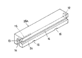
【図26】本発明の第2の実施の形態の端部接続用梁柱本体の斜視図。
【図27】本発明の第2の実施の形態の端部接続用梁柱本体の断面図。
【図28】本発明の第3の実施の形態の工程図。
【図29】本発明の第3の実施の形態の梁柱の説明図。
【図30】本発明の第3の実施の形態の接続梁柱の説明図。
【符号の説明】
1、1A、1B:梁柱設置工程、
2:軌道、
3:トンネル施工箇所、
4、4A:梁柱、 5:推進掘削装置、
6:梁柱挿入孔、 7:継手鋼管、
8:掘削工程、 9:棒鋼、
10:梁柱挿入工程、 11:梁柱本体、
12:突部状の嵌合部、 13:凹部状の嵌合部、
14:凹部溝状の嵌合部、15:棒鋼等の挿入孔、
16:支保工挿入凹部、 17、17A:接続梁柱設置工程、
18、18A:接続梁柱、19:接続用梁柱挿入孔、
20:接続用掘削工程、 21:接続用梁柱、
22:接続梁柱挿入工程、23:接続用梁柱本体、
24:突部状の嵌合部、 25:上部壁本体の設置工程、
26:上部壁本体、 27、27A:端部接続梁柱、
28、28A:端部接続用梁柱本体、
29:両側壁本体設置工程、
30:側壁本体、 31:下部壁本体設置工程、
32:下部壁本体、 33:支保工配設工程、
34:土砂、 35:支保工、
36:トンネル孔、 37:壁コンクリート打設工程、
38:壁コンクリート、 39:トンネル、
40:雌ねじ、 41:中間接続用梁柱、
42:中間接続用梁柱本体。[0001]
BACKGROUND OF THE INVENTION
The present invention relates to a tunnel excavation method and a beam column for excavating a relatively short tunnel such as a track, a road, and an underground buried object.
[0002]
[Prior art]
Conventionally, a pipe roof construction method, a pipe beam construction method, a URT construction method, a PCR construction method, a NNCB construction method and the like have been performed as excavation construction methods for this type of tunnel.
[0003]
[Problems to be solved by the invention]
The conventional pipe roof construction method has the disadvantages that the pipe is a temporary material and serves only as a soil retaining member, and it is necessary to deeply cover the pipe with a diameter of the pipe.
In addition, the pipe beam method has the disadvantages that the pipe is a temporary material and serves only as a retaining ring, and large temporary support beams are required on both sides.
Furthermore, the URT method, the PCR method, and the NNCB method all have a drawback that large temporary support beams are required on both sides.
[0004]
In view of the conventional drawbacks as described above, the present invention can perform excavation work of a tunnel using a beam column that is safe and economical in quality without using a large-scale facility, and the shape of the tunnel. The purpose is to provide a tunnel excavation method and a beam column that can be freely formed.
[0005]
The above and other objects and novel features of the present invention will become more fully apparent when the following description is read in conjunction with the accompanying drawings.
However, the drawings are for explanation only and do not limit the technical scope of the present invention.
[0006]
[Means for Solving the Problems]
In order to achieve the above-described object, the present invention provides a drilling process in which a joint steel pipe is sequentially pushed into the beam column insertion hole while excavating the beam column insertion hole from one side of the tunnel construction site, and the drilling process. The beam column is inserted through a beam column insertion step in which a plurality of beam columns formed with fitting portions that are fitted in the propulsion direction and the connection direction are sequentially inserted while pushing the joint steel pipe inserted into the beam column insertion hole later and ejected. Beam column installation process to be installed and the connection beam column insertion hole while excavating the connection beam column insertion hole from one side or the other side of the tunnel construction site of the side part of the beam column installed in this beam column installation process In the connecting drilling process, in which the joint steel pipes are sequentially inserted into the other side or one side, and the joint steel pipe inserted into the connecting beam post insertion hole after the connection drilling process is pushed in and discharged in the propulsion direction and the connection direction. Mating Connection beam Columns sequentially inserted to connect trabeculae inserting step while fitted with the trabeculae as a plurality of connecting beams Column fitting portion is formed and an end portion connecting trabeculae in the end portion is located The connecting beam column installation process for installing the connecting beam column, and the connecting beam column installation process are sequentially performed on the side surface portion of the connecting beam column installed in this connecting beam column installation process so that a large number of connecting beam columns are in parallel. The upper or lower wall main body installation process of the tunnel installed in the above and the upper or lower wall main body installed in the upper or lower wall main body both ends of the beam column and the connection beam column lower surface or upper surface of the connection The side wall main body installation process in which the same work as the beam pillar installation process is sequentially performed to install the both side wall main body, and the inner side surface of the connecting beam pillar at the end of the both side wall main body installed in the both side wall main body installation process. Follow the same steps as the connecting beam column installation process. The lower or upper wall main body is installed and the lower or upper wall main body is installed, and after the lower or upper wall main body installation process, the support is installed at predetermined intervals while excavating and removing the earth and sand in the upper and lower wall main bodies and both side wall main bodies. The excavation construction method of the tunnel is composed of the support arrangement process.
[0007]
Further, the present invention provides a prism-shaped beam column main body, a projection-like fitting portion formed at one end of the beam column main body, and a connected beam column formed at the other end of the beam column main body. A recessed fitting portion into which the protruding fitting portion of the main body is fitted, and a recessed groove-like or protruding fitting portion formed at substantially the center of both side surfaces of the beam post body. It constitutes a beam column.
[0008]
DETAILED DESCRIPTION OF THE INVENTION
Hereinafter, the present invention will be described in detail with reference to embodiments shown in the drawings.
[0009]
In the first embodiment of the present invention shown in FIGS. 1 to 21,
[0010]
As shown in FIGS. 3 and 4, the
When the
[0011]
[0012]
As shown in FIGS. 6 and 7, the connecting
When the connecting
[0013]
Note that the connecting
[0014]
[0015]
As shown in FIGS. 11 and 12, the end
When the end connecting
[0016]
29 is the same as the connection beam
[0017]
31 sequentially performs the same work as the connection beam
When the
When the intermediate connecting
[0018]
33 supports the
[0019]
37 is a wall concrete placing step for placing
[0020]
The
[0021]
Different Embodiments of the Invention
Next, different embodiments of the present invention shown in FIGS. 22 to 30 will be described. In the description of the different embodiments of the present invention, the same components as those in the first embodiment of the present invention are denoted by the same reference numerals, and redundant description is omitted.
[0022]
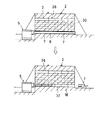
The second embodiment of the present invention shown in FIGS. 22 to 27 is mainly different from the first embodiment of the present invention in that one upper corner portion of the
In addition, the part connecting
[0023]
The third embodiment of the present invention shown in FIGS. 28 to 30 is mainly different from the first embodiment of the present invention in the beam column installation step 1B and the connecting beam column installation step 17A. 29 and FIG. 30, the
[0024]
In each of the embodiments of the present invention, the
The upper wall
Further, in order to efficiently form the upper wall
In addition, excavation work of the starting and reaching piles that install the
In each of the embodiments of the present invention, the
[0025]
【The invention's effect】
As is clear from the above description, the present invention has the following effects.
[0026]
(1) Drilling the beam column insertion hole from one side of the tunnel construction site while sequentially pushing the joint steel pipe into the beam column insertion hole and excavating to the other side. After this drilling step, it is inserted into the beam column insertion hole A beam column installation step of installing a beam column in a beam column insertion step of sequentially inserting a plurality of beam columns formed with a fitting portion that fits in the propulsion direction and the connection direction while pushing and discharging the joint steel pipe; While drilling the connecting beam column insertion hole from one side or the other side of the tunnel construction side of the beam column installed in this beam column installation process, insert joint steel pipes sequentially into the connecting beam column insertion hole A connecting excavation process for excavating to the other side or one side, and a fitting part that fits in the propulsion direction and the connection direction while pushing and discharging the joint steel pipe inserted into the connecting beam post insertion hole after this connection excavation process is formed a plurality of which are A connection beam column installation step of installing the connection beam Columns sequentially inserted to connect trabeculae insertion step while the allowed trabeculae and fitted to continue for trabeculae and end connection trabeculae in the end portion is located, The upper or lower wall body of the tunnel in which a plurality of connecting beam columns are installed in parallel by sequentially performing the same operation as the connecting beam column setting step on the side portion of the connecting beam column set in the connecting beam column setting step Steps similar to those in the connection beam column installation step are sequentially applied to the beam columns at both ends of the upper or lower wall body and the lower or upper surface of the connection beam column installed in the upper or lower wall body installation step. The both side wall main body installation process for installing both side wall main bodies and the same work as the connection beam pillar installation process on the inner side surface of the connection beam pillar at the end of the both side wall main body installed in the both side wall main body installation process. Sequentially perform the lower or upper wall Lower or upper wall main body installation process for installing the body, and support work placement process for arranging support works at predetermined intervals while excavating and removing the earth and sand in the upper and lower wall main bodies and both side wall main bodies after this lower or upper wall main body installation process Therefore, the beam pillars constituting the upper wall main body, the both side wall main body, and the lower wall main body can be fitted and connected by the fitting portion in the left-right direction.
Therefore, it is possible to install an upper wall body, both side wall bodies, and a lower wall body that can obtain sufficient strength.
[0027]
(2) According to (1), after the upper wall main body, the both side wall main body, and the lower wall main body are installed, the internal earth and sand are excavated, so that the excavation work can be performed safely.
[0028]
(3) According to the above (1), the shape of the tunnel can be freely changed by changing the number of connecting beam columns used when forming the upper wall body, the both side wall bodies, and the lower wall body.
[0029]
(4) According to the above (1), the beam pillars constituting the upper wall body, the both side wall bodies, and the lower wall body can be manufactured at the factory, the quality is constant, and they can be used with peace of mind. it can.
[0030]
(5) In the second, third, fourth, and fifth aspects, the same effects as the above (1) to (5) can be obtained.
[Brief description of the drawings]
FIG. 1 is a process diagram of a first embodiment of the present invention.
FIG. 2 is an explanatory diagram of a beam pillar installation process according to the first embodiment of this invention.
FIG. 3 is a perspective view of a beam post according to the first embodiment of the present invention.
FIG. 4 is a cross-sectional view of a beam post according to the first embodiment of the present invention.
FIG. 5 is an explanatory diagram of a connecting beam column installation step according to the first embodiment of this invention.
FIG. 6 is a perspective view of a connecting beam post according to the first embodiment of the present invention.
FIG. 7 is a cross-sectional view of the connecting beam post according to the first embodiment of the present invention.
FIG. 8 is an explanatory diagram of a connection state between a beam column and a connection beam column according to the first embodiment of this invention.
FIG. 9 is an explanatory diagram of an installation process of the upper wall main body according to the first embodiment of this invention.
FIG. 10 is an explanatory diagram of an upper wall main body according to the first embodiment of this invention.
FIG. 11 is a perspective view of an end connecting beam post according to the first embodiment of the present invention.
FIG. 12 is a cross-sectional view of the end connection beam column according to the first embodiment of the present invention.
FIG. 13 is an explanatory diagram of a both-side wall main body installation step according to the first embodiment of the present invention.
FIG. 14 is an explanatory diagram of the side wall body according to the first embodiment of the present invention.
FIG. 15 is an explanatory diagram of a lower wall main body installation process according to the first embodiment of this invention.
FIG. 16 is an explanatory diagram of a lower wall main body according to the first embodiment of this invention.
FIG. 17 is a perspective view of a beam column for intermediate connection according to the first embodiment of this invention.
FIG. 18 is a cross-sectional view of a beam column for intermediate connection according to the first embodiment of the present invention. FIG. 19 is an explanatory diagram of a support work arranging step according to the first embodiment of the present invention.
FIG. 20 is an explanatory diagram of an installation state of the support work according to the first embodiment of this invention.
FIG. 21 is an explanatory diagram of a wall concrete placing step according to the first embodiment of the present invention.
FIG. 22 is a process diagram of the second embodiment of the present invention.
FIG. 23 is an explanatory diagram of a beam pillar installation process according to the second embodiment of this invention.
FIG. 24 is an explanatory diagram of a connecting beam column installation process according to the second embodiment of this invention.
FIG. 25 is an explanatory diagram of an upper wall body according to a second embodiment of this invention.
FIG. 26 is a perspective view of an end connecting beam post main body according to a second embodiment of the present invention.
FIG. 27 is a cross-sectional view of an end connecting beam post main body according to a second embodiment of the present invention.
FIG. 28 is a process diagram of the third embodiment of the present invention;
FIG. 29 is an explanatory diagram of a beam post according to a third embodiment of this invention.
FIG. 30 is an explanatory diagram of a connecting beam column according to a third embodiment of this invention.
[Explanation of symbols]
1, 1A, 1B: beam pillar installation process,
2: Orbit,
3: Tunnel construction location,
4, 4A: beam column, 5: propulsion excavator,
6: Beam column insertion hole, 7: Joint steel pipe,
8: Drilling process, 9: Steel bar,
10: Beam column insertion process, 11: Beam column body,
12: a protrusion-like fitting portion, 13: a concave fitting portion,
14: recessed groove-like fitting portion, 15: insertion hole for steel bars,
16: support insertion recess, 17, 17A: connecting beam pillar installation process,
18, 18A: connecting beam column, 19: connecting beam column insertion hole,
20: excavation process for connection, 21: beam pillar for connection,
22: Connecting beam column insertion process, 23: Connecting beam column body,
24: protrusion-like fitting portion, 25: installation process of the upper wall main body,
26: Upper wall
28, 28A: beam column body for end connection,
29: Both side wall main body installation process,
30: Side wall body, 31: Lower wall body installation process,
32: Lower wall body, 33: Supporting installation process,
34: earth and sand, 35: support work,
36: Tunnel hole, 37: Wall concrete placing process,
38: Wall concrete, 39: Tunnel,
40: female thread, 41: beam column for intermediate connection,
42: Beam column body for intermediate connection.
Claims (8)
Priority Applications (1)
| Application Number | Priority Date | Filing Date | Title |
|---|---|---|---|
| JP16509599A JP4222686B2 (en) | 1999-06-11 | 1999-06-11 | Tunnel excavation method and beam columns |
Applications Claiming Priority (1)
| Application Number | Priority Date | Filing Date | Title |
|---|---|---|---|
| JP16509599A JP4222686B2 (en) | 1999-06-11 | 1999-06-11 | Tunnel excavation method and beam columns |
Publications (2)
| Publication Number | Publication Date |
|---|---|
| JP2000352295A JP2000352295A (en) | 2000-12-19 |
| JP4222686B2 true JP4222686B2 (en) | 2009-02-12 |
Family
ID=15805801
Family Applications (1)
| Application Number | Title | Priority Date | Filing Date |
|---|---|---|---|
| JP16509599A Expired - Lifetime JP4222686B2 (en) | 1999-06-11 | 1999-06-11 | Tunnel excavation method and beam columns |
Country Status (1)
| Country | Link |
|---|---|
| JP (1) | JP4222686B2 (en) |
Families Citing this family (1)
| Publication number | Priority date | Publication date | Assignee | Title |
|---|---|---|---|---|
| KR101381325B1 (en) * | 2013-05-30 | 2014-04-04 | 성은주 | The non-open cut tunnel construction method using the multistage small diameter steel pipe |
-
1999
- 1999-06-11 JP JP16509599A patent/JP4222686B2/en not_active Expired - Lifetime
Also Published As
| Publication number | Publication date |
|---|---|
| JP2000352295A (en) | 2000-12-19 |
Similar Documents
| Publication | Publication Date | Title |
|---|---|---|
| KR101161332B1 (en) | Construction method of the underground tunnel | |
| KR100794609B1 (en) | Construction method of underground structure using concrete filled pipe roof and concrete wall | |
| JP5686693B2 (en) | Invert construction method and precast member | |
| JP4881555B2 (en) | Construction method of underground structure | |
| KR100914158B1 (en) | Process of blocking water penetration and blocking earth collapsing by using impermeable wall without strut | |
| KR20070076553A (en) | Construction method of underground structure using concrete filled pipe roof and concrete wall | |
| KR20070052109A (en) | Down-ward construction method of the underground slabs and retaining walls by the slim-type composit floor system consisted of the architectural conposit deep deck and unsymmetric h-beam without preliminary wall-attached support beams and sub-beams of the floor | |
| JP2000265458A (en) | Floor slab connecting structure for underground structure with precast pile underground wall | |
| JP4486136B2 (en) | Caisson connection method | |
| KR101202182B1 (en) | pipe roof structures and its construction method | |
| KR100989984B1 (en) | Bult-in timbering roof type tunnel method | |
| JP4222686B2 (en) | Tunnel excavation method and beam columns | |
| KR101275468B1 (en) | The structure assembly for building a tunnel and building method thereof | |
| KR102310091B1 (en) | Underground structure installation method that does not require the installation of temporary pillars | |
| KR20100110927A (en) | Post tension tunnel method | |
| JP4153456B2 (en) | Construction method of steel element / concrete type underground structure | |
| JP3648664B2 (en) | Building renovation method and building | |
| KR101967167B1 (en) | The Method of Constructing Non-excavation Type Tunnel | |
| KR102610909B1 (en) | Method and structure of steel pipe propulsion using anchor installation inside steel pipe to prevent sinking | |
| KR101046794B1 (en) | Connection panel wall construction method of underground structure | |
| KR101285987B1 (en) | Improved Compound Roof Tunnel Method | |
| KR102633929B1 (en) | Casing for retaining wall construction and method for retaining wall construction using the same | |
| JPH01315520A (en) | Underground outer wall constructing method for superstructure | |
| KR102191503B1 (en) | The Tunnel construction method to use retangular pipe | |
| JP3646698B2 (en) | Construction method for underground structures |
Legal Events
| Date | Code | Title | Description |
|---|---|---|---|
| A621 | Written request for application examination |
Free format text: JAPANESE INTERMEDIATE CODE: A621 Effective date: 20060609 |
|
| A977 | Report on retrieval |
Free format text: JAPANESE INTERMEDIATE CODE: A971007 Effective date: 20071228 |
|
| A131 | Notification of reasons for refusal |
Free format text: JAPANESE INTERMEDIATE CODE: A131 Effective date: 20080826 |
|
| A521 | Written amendment |
Free format text: JAPANESE INTERMEDIATE CODE: A523 Effective date: 20080909 |
|
| TRDD | Decision of grant or rejection written | ||
| A01 | Written decision to grant a patent or to grant a registration (utility model) |
Free format text: JAPANESE INTERMEDIATE CODE: A01 Effective date: 20081111 |
|
| A01 | Written decision to grant a patent or to grant a registration (utility model) |
Free format text: JAPANESE INTERMEDIATE CODE: A01 |
|
| A61 | First payment of annual fees (during grant procedure) |
Free format text: JAPANESE INTERMEDIATE CODE: A61 Effective date: 20081118 |
|
| R150 | Certificate of patent or registration of utility model |
Free format text: JAPANESE INTERMEDIATE CODE: R150 Ref document number: 4222686 Country of ref document: JP Free format text: JAPANESE INTERMEDIATE CODE: R150 |
|
| FPAY | Renewal fee payment (event date is renewal date of database) |
Free format text: PAYMENT UNTIL: 20111128 Year of fee payment: 3 |
|
| FPAY | Renewal fee payment (event date is renewal date of database) |
Free format text: PAYMENT UNTIL: 20141128 Year of fee payment: 6 |
|
| R250 | Receipt of annual fees |
Free format text: JAPANESE INTERMEDIATE CODE: R250 |
|
| R250 | Receipt of annual fees |
Free format text: JAPANESE INTERMEDIATE CODE: R250 |
|
| R250 | Receipt of annual fees |
Free format text: JAPANESE INTERMEDIATE CODE: R250 |
|
| EXPY | Cancellation because of completion of term |


