JP4222003B2 - Clean room cassette positioning device - Google Patents
Clean room cassette positioning device Download PDFInfo
- Publication number
- JP4222003B2 JP4222003B2 JP2002330890A JP2002330890A JP4222003B2 JP 4222003 B2 JP4222003 B2 JP 4222003B2 JP 2002330890 A JP2002330890 A JP 2002330890A JP 2002330890 A JP2002330890 A JP 2002330890A JP 4222003 B2 JP4222003 B2 JP 4222003B2
- Authority
- JP
- Japan
- Prior art keywords
- positioning
- cassette
- suspension frame
- suspension
- clean room
- Prior art date
- Legal status (The legal status is an assumption and is not a legal conclusion. Google has not performed a legal analysis and makes no representation as to the accuracy of the status listed.)
- Expired - Lifetime
Links
Images
Landscapes
- Container, Conveyance, Adherence, Positioning, Of Wafer (AREA)
Description
【0001】
【発明の属する技術分野】
本発明は、クリーンルーム内においてカセットの位置決めが容易にでき、且つ発塵を防止できるクリーンルームのカセット位置決め装置に関するものである。
【0002】
【従来の技術】
従来より、半導体等の薄型基板を収納するカセットは、半導体または液晶プロセスにより各々のプロセス装置のカセットステーションへAGV(自動搬送車)等より搬送される。そして、カセットステーションに搬入されたカセットはロボットによる薄型基板の受け渡しを行うために、所定の位置に位置決めされる。
【0003】
従来のカセットの位置決め装置には、傾きが調整可能な基台の上部に、カセットの底面四隅部分を別個に支持する支持部材と、各支持部材に立設してカセットの周面部位に当接してカセットの水平位置を規制するガイド部材を備えたものがある(例えば、特許文献1参照)。
【0004】
また、カセットを受ける2つの架台を間隔を隔てて配置し、各架台を4つのころ台により滑動可能に支持し、架台上に載置したカセットをクランパーによりストッパに押付けて位置決めするようにしたものもある(例えば、特許文献2参照)。
【0005】
【特許文献1】
特開平9−148423号公報
【特許文献2】
特開平8−321541号公報
【0006】
【発明が解決しようとする課題】
しかし、前記特許文献1では、カセットの周面がガイド部材に摺接することによりカセットの水平位置を規制する構成であるために、カセットの摺動によってカセットとガイド部材との間に塵が発生することになり、もともとクリーンルーム内で行われる半導体等の作業には適していなかった。
【0007】
また、前記記特許文献2では、架台をころ台にて滑動可能に支持しており、更に、カセットの前後、左右、回転方向の位置決めをクランパーでストッパに押付けることによって行っているため、架台ところ台の接触により塵が発生する問題があり、更にクランパーとストッパによる接触の繰返しによっても塵が発生し、また重量が大きい大型のカセットの場合には接触力の増加によって塵の発生が更に増加する問題がある。
【0008】
本発明は、クリーンルーム内におけるカセットの位置決めが容易にでき、しかも塵の発生を防止できるようにしたクリーンルームのカセット位置決め装置を提供することを目的とする。
【0009】
【課題を解決するための手段】
請求項1に記載の発明は、クリーンルーム内で搬送されるカセットを受けて位置決めを行うためのカセット位置決め装置であって、固定部材から揺動可能な吊り材により水平方向に揺動自在に吊り下げた吊り枠と、前記吊り材を気密に包囲する防塵カバーと、前記吊り枠の外側上部に配置して載置されるカセットに対し吊り枠を位置決めする案内ローラと、前記吊り枠の下面に設けた位置決め穴を有する位置決めボスと、前記固定部材に設けられ位置決めピンを昇降して前記位置決めボスの位置決め穴に嵌脱させる位置決め駆動装置と、前記位置決めピンが通過する開口を備えて前記位置決めピン及び位置決め駆動装置を包囲し吸引装置に接続された吸引用カバーと、を備えたことを特徴とするクリーンルームのカセット位置決め装置、に係るものである。
【0010】
請求項2に記載の発明は、前記案内ローラは、吊り枠の4角部に配置されカセットのコーナ部の2面を案内する直交したローラ対であることを特徴とする請求項1に記載のクリーンルームのカセット位置決め装置、に係るものである。
【0011】
請求項3に記載の発明は、前記案内ローラは、非発塵性材料にて構成されていることを特徴とする請求項1又は2に記載のクリーンルームのカセット位置決め装置、に係るものである。
【0012】
請求項4に記載の発明は、前記位置決めピンを有する位置決め駆動装置と位置決めボスは、少なくとも2個所に設置していることを特徴とする請求項1に記載のクリーンルームのカセット位置決め装置、に係るものである。
【0013】
本発明によれば、以下のように作用する。
【0014】
請求項1に記載の発明では、固定部材から揺動可能な吊り材により水平方向に揺動自在に吊り下げた吊り枠と、前記吊り枠の外側上部に配置して載置されるカセットに対し吊り枠を位置決めする案内ローラとを備えているので、カセットを吊り枠上に接近させて載置するとき、カセットと吊り枠に位置ずれがあっても案内ローラの案内によりカセットに対して吊り枠が揺動して位置決めされる。続いて、カセットの荷重を吊り枠に渡すと、吊り枠は吊り材にて揺動可能に吊り下げられているので重心位置により自動調芯されて位置決めされる。従って、このときカセットと案内ローラとの間には大きな力を作用させることなく位置決めできるので、塵が発生する問題を防止できる。
【0015】
続いて、固定部材に設けた位置決め駆動装置により位置決めピンを上昇させて吊り枠の下面に設けた位置決めボスの位置決め穴に嵌合することにより、吊り枠及びカセットは正確な位置に位置決めされ、よってロボットによるカセットの薄型基板の受け渡し等の作業が確実にできる。
【0016】
前記吊り材は防塵カバーで包囲しており、また位置決めピン及び位置決め駆動装置は吸引用カバーで包囲し且つ吸引装置で吸引するようにしているので、接触部からの塵がクリーンルーム内に飛散する問題を確実に防止できる。
【0017】
請求項2に記載の発明では、案内ローラが、吊り枠の4角部に配置されカセットのコーナ部の2面を案内する直交したローラ対であるので、簡単な構成にてカセットの位置決めを正確にできる。
【0018】
請求項3に記載の発明では、案内ローラが、非発塵性材料にて構成されているので、カセットに接する案内ローラからの発塵を防止できる。
【0019】
請求項4に記載の発明では、位置決めピンを有する位置決め駆動装置と位置決めボスを少なくとも2個所に設置しているので、カセットの前後、左右、回転方向の設置決めを正確に行える。
【0020】
【発明の実施の形態】
以下、本発明の好適な実施の形態を図面に基づいて説明する。
【0021】
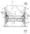
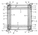
図1は本発明のカセット位置決め装置の全体構成を表わす正面図、図2は図1をII−II方向から見た平面図、図3は図1をIII−III方向から見た側面図である。図1〜図3では、床上には平面視で矩形配置になるように4本のラック柱1a,1b,1c,1dが立設されており、左側におけるラック柱1a,1c間と、右側におけるラック柱1b,1d間の夫々の所要の高さ位置には前後に延びる台フレーム2が一体に固定されている。更に、前記台フレーム2上における前後両端部から所要の距離を隔てた位置には、平面視で矩形配置になるように4本の所要高さの固定マスト3a,3b,3c,3dが立設されている。そして、前側の固定マスト3a,3b間と後側の固定マスト3c,3d間、及び左側の固定マスト3a,3c間と右側の固定マスト3b,3d間は、夫々マスト補強材4にて一体に固定されている。上記ラック柱1a,1b,1c,1d、台フレーム2、固定マスト3a,3b,3c,3d及びマスト補強材4によって固定部材5が構成されている。
【0022】
前側の固定マスト3a,3bの上端には前方に延びる水平部材6が固定され、また後側の固定マスト3c,3dの上端には後方に延びる水平部材6が固定されており、上記各水平部材6には揺動可能な吊り材7が取付けられており、該4本の吊り材7によって吊り枠8が水平方向に揺動自在に吊り下げられている。
【0023】
前記吊り枠8は、左右の両端が前記水平部材6の下部に位置するように左右方向に長く形成した前後の細長枠体9a,9bと、前後の細長枠体9a,9bの左右両端から所要の距離だけ内側位置の間を相互に連結する連結材10と、連結材10上部と前記細長枠体9a,9bの両端上部に補助フレーム11を備えて前記水平部材6の下部に立体的に組み立てた4個の張出し支持部12を備えている。そして、前記吊り枠8は、細長枠体9a,9bと張出し支持部12とにより、図1で示す正面形状が凹形を有してスライドフォーク13の挿入空間を形成するようになっている。更に左側の補助フレーム11の上部間及び右側の補助フレーム11の上部間には前後に伸びるステンレス材等のカセット受け板14が固定されている。
【0024】
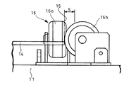
前記各張出し支持部12の補助フレーム11上には、図4、図7、図8に示すように、カセット受け板14上に載置されるカセット15の位置決めを行うための案内ローラ16が設けられており、4個所の案内ローラ16によってカセット15の位置決めを行うようにしている。案内ローラ16は、カセット15のコーナ部の2面を案内するように直交したローラ対16a,16bからなっている。上部から吊り枠8のカセット受け板14上に載置されるカセット15は、前記案内ローラ16の周面によって誤差範囲Sで案内され、このとき吊り枠8は吊り材7にて水平方向に揺動可能に支持されているので、案内ローラ16により吊り枠8がカセット15に追随して位置決めされてカセット15はカセット受け板14上に載置されるようになっている。前記案内ローラ16は、カセット15との接触により塵が発生し難いUPE(ウルトラ高分子ポリエチレン)或いはMCナイロン、テフロン(登録商標)等の樹脂からなる非発塵性材料にて構成されている。
【0025】
前記吊り材7は、図4、図5、図6に示すように、吊りロッド17が前記水平部材6に形成した開口18と吊り枠8に設けた張出し支持部12の補助フレーム11に形成した開口18とを遊嵌状態に貫通しており、吊りロッド17の上端には固定頭部19が設けられ、水平部材6上に固定台20を介して設けた球面座金21上に前記固定頭部19が載置されている。また、吊りロッド17の下端には固定用ナット22が設けられており、吊り枠8の補助フレーム11の下面に固定台23を介して設けた球面座金24を前記固定用ナット22により支持している。従って、前記吊りロッド17は球面座金21,24を介して吊り枠8を水平方向に揺動可能に吊り下げている。
【0026】
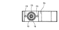
また、前記水平部材6上には、図4、図5に示すように球面座金21及び固定頭部19の外周を包囲する防塵カバー25をボルト26により固定している。更に、吊り枠8の補助フレーム11の下面には、図4、図6に示すように球面座金24及び固定用ナット22を包囲する防塵カバー27を配置してボルト28により補助フレーム11の側面に固定している。
【0027】
また、前記吊りロッド17が貫通する水平部材6の下面と補助フレーム11の上面には固定筒体29a,29bが設けられており、該固定筒体29a,29bの外周面間には、可撓性のホース或いは蛇腹等からなる防塵カバー30が固定バンド31等により固定されている。
【0028】
また、前記吊り枠8の張出し支持部12の夫々の下面位置には、図9、図10に示すように鉛直の位置決め穴32を有する位置決めボス33が固定されている。更に、前記固定部材5における左右のマスト補強材4には前記固定マスト3a,3b,3c,3dから更に前後に延長させた延長部4’を設け、この延長部4’には位置決め駆動装置34を設置している。位置決め駆動装置34は、駆動シリンダ35により前記位置決めボス33の位置決め穴32の下部に位置した位置決めピン36を昇降させて、前記位置決めボス33の位置決め穴32に位置決めピン36を嵌脱させるよう構成している。更に、前記位置決めピン36が通過する開口37を上部に備えて前記位置決めピン36及び位置決め駆動装置34を包囲する吸引用カバー38を設けている。該吸引用カバー38は吸引装置39に接続されていて吸引用カバー38の内部を吸引するようにしている。図中40は前記位置決め駆動装置34の左右方向の位置決めを行うための位置決めボルトである。前記した位置決めボス33も、位置決めピン36の接触により塵が発生し難いUPE(ウルトラ高分子ポリエチレン)或いはMCナイロン、テフロン(登録商標)等の樹脂からなる非発塵性材料にて構成してもよい。
【0029】
図1〜図3の例では、位置決めピン36を有する位置決め駆動装置34と位置決めボス33を4個所に配置した場合を示しているが、吊り枠8の前後、左右、回転方向の設置決めを行うには2個所以上設置すればよい。
【0030】
以下に、上記形態例の作用を説明する。
【0031】
上記したように、固定部材5の固定マスト3a,3b,3c,3dから揺動可能な吊り材7により水平方向に揺動自在に吊り枠8を吊り下げ、該吊り枠8の外側上部の4個所に、載置されるカセット15に対し吊り枠8を位置決めする案内ローラ16を備えた構成としているので、カセット15を吊り枠8上に吊降ろして載置するとき、カセット15と吊り枠8との間に位置ずれがあっても案内ローラ16の案内によりカセット15に対して吊り枠8が揺動して位置決めされるようになる。続いて、カセット15の荷重が吊り枠8に渡されると、吊り枠8は吊り材7にて揺動可能に吊り下げられているので重心位置により自動調芯されて位置決めされる。従って、このときカセット15と案内ローラ16との間には大きな力を作用させることなく位置決めできるので、塵が発生する問題を防止できる。
【0032】
続いて、固定部材5に設けた位置決め駆動装置34により位置決めピン36を上昇させて吊り枠8の下面に設けた位置決めボス33の位置決め穴32に嵌合させると、吊り枠8及びカセット15は正確な位置に位置決めされる。これにより、ロボットによるカセット15の薄型基板の受け渡し等の作業が確実に行えるようになる。
【0033】
前記吊り材7は防塵カバー25,27,30で包囲されており、また位置決めピン36及び位置決め駆動装置34は吸引用カバー38で包囲され且つ吸引用カバー38の内部は吸引装置39により吸引されているので、接触部からの塵がクリーンルーム内に飛散する問題を確実に防止できる。
【0034】
また、前記案内ローラ16は、吊り枠8の4角部に配置されてカセット15のコーナ部の2面を案内する直交したローラ対16a,16bとしているので、簡単な構成にてカセット15の位置決めを正確に行える。更に、案内ローラ16が、非発塵性材料にて構成されているので、カセット15に接する案内ローラ16からの発塵は防止される。
【0035】
更に、位置決めピン36を有する位置決め駆動装置34と位置決めボス33を少なくとも2個所に設置しているので、カセット15の前後、左右、回転方向の設置決めを正確に行うことができる。
【0036】
尚、本発明は上記形態例にのみ限定されるものではなく、固定部材、吊り枠の形状は種々変更し得ること、位置決め駆動装置及び位置決めボスの設置位置は種々変更し得ること、案内ローラをテーパー付ガイド等に変更し得ること、その他本発明の要旨を逸脱しない範囲内において種々変更を加え得ること、等は勿論である。
【0037】
【発明の効果】
本発明によれば、以下のような効果を奏する。
【0038】
請求項1に記載の発明によれば、固定部材から揺動可能な吊り材により水平方向に揺動自在に吊り下げた吊り枠と、前記吊り枠の外側上部に配置して載置されるカセットに対し吊り枠を位置決めする案内ローラとを備えているので、カセットを吊り枠上に接近させて載置するとき、カセットと吊り枠に位置ずれがあっても案内ローラの案内によりカセットに対して吊り枠が揺動して位置決めされる。続いて、カセットの荷重を吊り枠に渡すと、吊り枠は吊り材にて揺動可能に吊り下げられているので重心位置により自動調芯されて位置決めされる。従って、このときカセットと案内ローラとの間には大きな力を作用させることなく位置決めできるので、塵が発生する問題を防止できる効果がある。
【0039】
続いて、固定部材に設けた位置決め駆動装置により位置決めピンを上昇させて吊り枠の下面に設けた位置決めボスの位置決め穴に嵌合することにより、吊り枠及びカセットは正確な位置に位置決めされ、よってロボットによるカセットの薄型基板の受け渡し等の作業が確実にできる効果がある。
【0040】
前記吊り材は防塵カバーで包囲しており、また位置決めピン及び位置決め駆動装置は吸引用カバーで包囲し且つ吸引装置で吸引するようにしているので、接触部からの塵がクリーンルーム内に飛散する問題を確実に防止できる効果がある。
【0041】
請求項2に記載の発明によれば、案内ローラが、吊り枠の4角部に配置されカセットのコーナ部の2面を案内する直交したローラ対であるので、簡単な構成にてカセットの位置決めを正確にできる効果がある。
【0042】
請求項3に記載の発明によれば、案内ローラが、非発塵性材料にて構成されているので、カセットに接する案内ローラからの発塵を防止できる効果がある。
【0043】
請求項4に記載の発明によれば、位置決めピンを有する位置決め駆動装置と位置決めボスを少なくとも2個所に設置しているので、カセットの前後、左右、回転方向の設置決めを正確に行える効果がある。
【図面の簡単な説明】
【図1】本発明のカセット位置決め装置の全体構成を表わす正面図である。
【図2】図1をII−II方向から見た平面図である。
【図3】図1をIII−III方向から見た側面図である。
【図4】本発明のカセット位置決め装置における吊り材の拡大断面図である。
【図5】図4のV−V方向矢視図である。
【図6】図4のVI−VI方向矢視図である。
【図7】本発明のカセット位置決め装置における案内ローラの拡大平面図である。
【図8】図7の正面図である。
【図9】本発明のカセット位置決め装置における位置決め駆動装置と位置決めボスの構成例を示す拡大正面図である。
【図10】図9のX−X方向矢視図である。
【符号の説明】
3a,3b,3c,3d 固定マスト(固定部材)
5 固定部材
7 吊り材
8 吊り枠
15 カセット
16 案内ローラ
16a,16b ローラ対
25 防塵カバー
27 防塵カバー
30 防塵カバー
32 位置決め穴
33 位置決めボス
34 位置決め駆動装置
36 位置決めピン
37 開口
38 吸引用カバー
39 吸引装置[0001]
BACKGROUND OF THE INVENTION
The present invention relates to a cassette positioning device for a clean room that can easily position a cassette in a clean room and prevent dust generation.
[0002]
[Prior art]
Conventionally, a cassette for storing a thin substrate such as a semiconductor is conveyed from an AGV (automatic conveyance vehicle) or the like to a cassette station of each process apparatus by a semiconductor or liquid crystal process. Then, the cassette carried into the cassette station is positioned at a predetermined position in order to transfer the thin substrate by the robot.
[0003]
In the conventional cassette positioning device, a support member that separately supports the four corners of the bottom surface of the cassette is provided on the upper portion of the base whose tilt can be adjusted, and the support member is erected on each support member so as to abut on the peripheral surface portion of the cassette. Some of them have a guide member that regulates the horizontal position of the cassette (see, for example, Patent Document 1).
[0004]
In addition, two bases that receive cassettes are arranged at intervals, each base is slidably supported by four roller bases, and the cassette placed on the base is pressed against a stopper by a clamper and positioned. (For example, refer to Patent Document 2).
[0005]
[Patent Document 1]
JP-A-9-148423 [Patent Document 2]
JP-A-8-321541 [0006]
[Problems to be solved by the invention]
However, in the above-mentioned
[0007]
In
[0008]
An object of the present invention is to provide a cassette positioning device for a clean room which can easily position the cassette in the clean room and prevent dust from being generated.
[0009]
[Means for Solving the Problems]
The invention according to
[0010]
The invention according to
[0011]
The invention according to
[0012]
According to a fourth aspect of the present invention, there is provided the cleanroom cassette positioning device according to the first aspect, wherein the positioning driving device having the positioning pin and the positioning boss are installed in at least two locations. It is.
[0013]
The present invention operates as follows.
[0014]
According to the first aspect of the present invention, a suspension frame suspended in a swingable manner in a horizontal direction by a suspension member that can swing from a fixed member, and a cassette that is placed and placed on the outside upper portion of the suspension frame. Since the guide roller for positioning the suspension frame is provided, when the cassette is placed close to the suspension frame, even if the cassette and the suspension frame are misaligned, the suspension frame with respect to the cassette is guided by the guide roller. Swings and is positioned. Subsequently, when the cassette load is passed to the suspension frame, the suspension frame is suspended by the suspension material so as to be swingable, and thus is automatically aligned and positioned by the position of the center of gravity. Therefore, since it can position without applying a big force between a cassette and a guide roller at this time, the problem which dust generate | occur | produces can be prevented.
[0015]
Subsequently, the positioning frame is raised by the positioning driving device provided on the fixing member and fitted into the positioning hole of the positioning boss provided on the lower surface of the suspension frame, so that the suspension frame and the cassette are positioned at the correct positions. Work such as delivery of a thin substrate of a cassette by a robot can be reliably performed.
[0016]
The suspension material is surrounded by a dustproof cover, and the positioning pin and the positioning drive device are surrounded by a suction cover and sucked by the suction device, so that the dust from the contact portion is scattered in the clean room. Can be reliably prevented.
[0017]
In the second aspect of the present invention, since the guide roller is a pair of orthogonal rollers arranged at the four corners of the suspension frame and guiding the two surfaces of the corner portion of the cassette, the cassette can be accurately positioned with a simple configuration. Can be.
[0018]
In the invention described in
[0019]
In the invention according to the fourth aspect, since the positioning drive device having the positioning pins and the positioning bosses are installed in at least two places, it is possible to accurately determine the installation of the front and rear, the left and right, and the rotation direction of the cassette.
[0020]
DETAILED DESCRIPTION OF THE INVENTION
DESCRIPTION OF EXEMPLARY EMBODIMENTS Hereinafter, preferred embodiments of the invention will be described with reference to the drawings.
[0021]
1 is a front view showing the overall configuration of the cassette positioning device of the present invention, FIG. 2 is a plan view of FIG. 1 viewed from the II-II direction, and FIG. 3 is a side view of FIG. 1 viewed from the III-III direction. . In FIG. 1 to FIG. 3, four
[0022]
A
[0023]
The
[0024]
[0025]
As shown in FIGS. 4, 5, and 6, the
[0026]
On the
[0027]
[0028]
A
[0029]
In the example of FIGS. 1 to 3, the
[0030]
The operation of the above embodiment will be described below.
[0031]
As described above, the
[0032]
Subsequently, when the
[0033]
The
[0034]
Further, since the
[0035]
Furthermore, since the
[0036]
The present invention is not limited to the above-described embodiments. The shape of the fixing member and the suspension frame can be changed variously. The installation positions of the positioning drive device and the positioning boss can be changed variously. Of course, it can be changed to a tapered guide or the like, and various changes can be made without departing from the scope of the present invention.
[0037]
【The invention's effect】
The present invention has the following effects.
[0038]
According to the first aspect of the present invention, a hanging frame suspended in a swingable manner in a horizontal direction by a suspension member that can swing from a fixed member, and a cassette that is placed and placed on the outer upper portion of the hanging frame. The guide roller for positioning the suspension frame with respect to the cassette, when the cassette is placed close to the suspension frame, the guide roller guides the cassette even if the cassette and the suspension frame are misaligned. The suspension frame swings and is positioned. Subsequently, when the cassette load is passed to the suspension frame, the suspension frame is suspended by the suspension material so as to be swingable, and thus is automatically aligned and positioned by the position of the center of gravity. Therefore, since it can position without applying a big force between a cassette and a guide roller at this time, there exists an effect which can prevent the problem which dust generate | occur | produces.
[0039]
Subsequently, the positioning frame is raised by the positioning driving device provided on the fixing member and fitted into the positioning hole of the positioning boss provided on the lower surface of the suspension frame, so that the suspension frame and the cassette are positioned at the correct positions. There is an effect that the operation such as delivery of the thin substrate of the cassette by the robot can be reliably performed.
[0040]
The suspension material is surrounded by a dustproof cover, and the positioning pin and the positioning drive device are surrounded by a suction cover and sucked by the suction device, so that the dust from the contact portion is scattered in the clean room. There is an effect that can be surely prevented.
[0041]
According to the second aspect of the present invention, since the guide rollers are a pair of orthogonal rollers arranged at the four corners of the suspension frame and guiding the two corners of the cassette, the cassette can be positioned with a simple configuration. There is an effect that can accurately
[0042]
According to the invention described in
[0043]
According to the fourth aspect of the present invention, since the positioning driving device having the positioning pins and the positioning bosses are installed in at least two places, there is an effect that the installation determination of the front and rear, the left and right, and the rotation direction of the cassette can be accurately performed. .
[Brief description of the drawings]
FIG. 1 is a front view showing the overall configuration of a cassette positioning device of the present invention.
FIG. 2 is a plan view of FIG. 1 viewed from the II-II direction.
FIG. 3 is a side view of FIG. 1 viewed from the III-III direction.
FIG. 4 is an enlarged sectional view of a suspension member in the cassette positioning device of the present invention.
5 is a VV direction arrow view of FIG. 4;
6 is a view taken in the direction of the arrow VI-VI in FIG. 4;
FIG. 7 is an enlarged plan view of a guide roller in the cassette positioning device of the present invention.
FIG. 8 is a front view of FIG. 7;
FIG. 9 is an enlarged front view showing a configuration example of a positioning drive device and a positioning boss in the cassette positioning device of the present invention.
10 is a view taken in the direction of arrows XX in FIG.
[Explanation of symbols]
3a, 3b, 3c, 3d Fixed mast (fixed member)
5 Fixing
Claims (4)
Priority Applications (1)
| Application Number | Priority Date | Filing Date | Title |
|---|---|---|---|
| JP2002330890A JP4222003B2 (en) | 2002-11-14 | 2002-11-14 | Clean room cassette positioning device |
Applications Claiming Priority (1)
| Application Number | Priority Date | Filing Date | Title |
|---|---|---|---|
| JP2002330890A JP4222003B2 (en) | 2002-11-14 | 2002-11-14 | Clean room cassette positioning device |
Publications (2)
| Publication Number | Publication Date |
|---|---|
| JP2004165488A JP2004165488A (en) | 2004-06-10 |
| JP4222003B2 true JP4222003B2 (en) | 2009-02-12 |
Family
ID=32808441
Family Applications (1)
| Application Number | Title | Priority Date | Filing Date |
|---|---|---|---|
| JP2002330890A Expired - Lifetime JP4222003B2 (en) | 2002-11-14 | 2002-11-14 | Clean room cassette positioning device |
Country Status (1)
| Country | Link |
|---|---|
| JP (1) | JP4222003B2 (en) |
Families Citing this family (2)
| Publication number | Priority date | Publication date | Assignee | Title |
|---|---|---|---|---|
| FR2885412B1 (en) * | 2005-05-03 | 2008-12-05 | Commissariat Energie Atomique | DEVICE AND METHOD FOR COLLECTING AND TRANSPORTING |
| JP5984038B2 (en) * | 2011-04-06 | 2016-09-06 | 株式会社東京精密 | Dicing machine |
-
2002
- 2002-11-14 JP JP2002330890A patent/JP4222003B2/en not_active Expired - Lifetime
Also Published As
| Publication number | Publication date |
|---|---|
| JP2004165488A (en) | 2004-06-10 |
Similar Documents
| Publication | Publication Date | Title |
|---|---|---|
| US7314344B2 (en) | Substrate-transporting device | |
| KR101438161B1 (en) | Probe card container | |
| KR101841257B1 (en) | Position adjusting device for plant | |
| KR102587470B1 (en) | Plan work table machine with elevation structure | |
| JP4222003B2 (en) | Clean room cassette positioning device | |
| TWI821552B (en) | Traveling vehicle system | |
| CN108792624A (en) | Automatic charging device | |
| JP2001144166A (en) | Substrate-positioning apparatus and substrate-handling method | |
| JP2001345367A (en) | Truck for attaching and detaching wafer transfer robot | |
| JPH07187349A (en) | Vibration control carrying stand for unmanned carrying vehicle or the like | |
| JPH05319770A (en) | Plate material conveying machine | |
| KR20160115123A (en) | Loading and unloading apparatus having vaccum suction part and high degrees of freedom joint | |
| JPH05192956A (en) | Injection molding machine | |
| JP4053275B2 (en) | Automated guided vehicle | |
| JPH06305561A (en) | Method and device for fixing glass plate | |
| CN211366079U (en) | Automatic turning device | |
| KR102403312B1 (en) | Glass fixing device | |
| JP4021469B1 (en) | Equipment for handling plate-like materials | |
| CN110884718A (en) | Photovoltaic module selects separately to erect and adorns device | |
| JPS61235335A (en) | Conveying device for lead frame | |
| JP3774589B2 (en) | Adsorption transfer equipment | |
| JP2020001844A (en) | Transportation vehicle and cargo handling gear | |
| CN221872205U (en) | Loading device and processing equipment | |
| JPH0811078A (en) | Robot hand | |
| JPH026011Y2 (en) |
Legal Events
| Date | Code | Title | Description |
|---|---|---|---|
| A621 | Written request for application examination |
Free format text: JAPANESE INTERMEDIATE CODE: A621 Effective date: 20051017 |
|
| A977 | Report on retrieval |
Free format text: JAPANESE INTERMEDIATE CODE: A971007 Effective date: 20080630 |
|
| TRDD | Decision of grant or rejection written | ||
| A01 | Written decision to grant a patent or to grant a registration (utility model) |
Free format text: JAPANESE INTERMEDIATE CODE: A01 Effective date: 20081028 |
|
| A01 | Written decision to grant a patent or to grant a registration (utility model) |
Free format text: JAPANESE INTERMEDIATE CODE: A01 |
|
| A61 | First payment of annual fees (during grant procedure) |
Free format text: JAPANESE INTERMEDIATE CODE: A61 Effective date: 20081110 |
|
| R151 | Written notification of patent or utility model registration |
Ref document number: 4222003 Country of ref document: JP Free format text: JAPANESE INTERMEDIATE CODE: R151 |
|
| FPAY | Renewal fee payment (event date is renewal date of database) |
Free format text: PAYMENT UNTIL: 20111128 Year of fee payment: 3 |
|
| FPAY | Renewal fee payment (event date is renewal date of database) |
Free format text: PAYMENT UNTIL: 20121128 Year of fee payment: 4 |
|
| FPAY | Renewal fee payment (event date is renewal date of database) |
Free format text: PAYMENT UNTIL: 20131128 Year of fee payment: 5 |
|
| R250 | Receipt of annual fees |
Free format text: JAPANESE INTERMEDIATE CODE: R250 |
|
| R250 | Receipt of annual fees |
Free format text: JAPANESE INTERMEDIATE CODE: R250 |
|
| EXPY | Cancellation because of completion of term |


