JP4218711B2 - Face detection device, imaging device, and face detection method - Google Patents
Face detection device, imaging device, and face detection method Download PDFInfo
- Publication number
- JP4218711B2 JP4218711B2 JP2006212841A JP2006212841A JP4218711B2 JP 4218711 B2 JP4218711 B2 JP 4218711B2 JP 2006212841 A JP2006212841 A JP 2006212841A JP 2006212841 A JP2006212841 A JP 2006212841A JP 4218711 B2 JP4218711 B2 JP 4218711B2
- Authority
- JP
- Japan
- Prior art keywords
- face detection
- face
- signal processing
- circuit
- processing circuit
- Prior art date
- Legal status (The legal status is an assumption and is not a legal conclusion. Google has not performed a legal analysis and makes no representation as to the accuracy of the status listed.)
- Expired - Fee Related
Links
Images


Classifications
-
- H—ELECTRICITY
- H04—ELECTRIC COMMUNICATION TECHNIQUE
- H04N—PICTORIAL COMMUNICATION, e.g. TELEVISION
- H04N5/00—Details of television systems
- H04N5/222—Studio circuitry; Studio devices; Studio equipment
- H04N5/262—Studio circuits, e.g. for mixing, switching-over, change of character of image, other special effects ; Cameras specially adapted for the electronic generation of special effects
-
- G—PHYSICS
- G06—COMPUTING; CALCULATING OR COUNTING
- G06V—IMAGE OR VIDEO RECOGNITION OR UNDERSTANDING
- G06V40/00—Recognition of biometric, human-related or animal-related patterns in image or video data
- G06V40/10—Human or animal bodies, e.g. vehicle occupants or pedestrians; Body parts, e.g. hands
- G06V40/16—Human faces, e.g. facial parts, sketches or expressions
- G06V40/161—Detection; Localisation; Normalisation
-
- G—PHYSICS
- G06—COMPUTING; CALCULATING OR COUNTING
- G06F—ELECTRIC DIGITAL DATA PROCESSING
- G06F18/00—Pattern recognition
-
- G—PHYSICS
- G06—COMPUTING; CALCULATING OR COUNTING
- G06V—IMAGE OR VIDEO RECOGNITION OR UNDERSTANDING
- G06V10/00—Arrangements for image or video recognition or understanding
- G06V10/40—Extraction of image or video features
-
- H—ELECTRICITY
- H04—ELECTRIC COMMUNICATION TECHNIQUE
- H04N—PICTORIAL COMMUNICATION, e.g. TELEVISION
- H04N23/00—Cameras or camera modules comprising electronic image sensors; Control thereof
-
- H—ELECTRICITY
- H04—ELECTRIC COMMUNICATION TECHNIQUE
- H04N—PICTORIAL COMMUNICATION, e.g. TELEVISION
- H04N23/00—Cameras or camera modules comprising electronic image sensors; Control thereof
- H04N23/60—Control of cameras or camera modules
- H04N23/61—Control of cameras or camera modules based on recognised objects
- H04N23/611—Control of cameras or camera modules based on recognised objects where the recognised objects include parts of the human body
Description
本発明は、入力された画像から人物の顔を検出する顔検出装置、その機能を備えた撮像装置、および顔検出方法に関する。 The present invention relates to a face detection device that detects a human face from an input image, an imaging device having the function, and a face detection method.
近年、デジタルスチルカメラ、デジタルビデオカメラなどのデジタル方式の撮像装置が急速に普及し、これらの製品の高性能化が進んでいる。このため、撮像装置としてより高度な機能を搭載して、その商品価値を高めることが強く求められている。このような高度な機能の一つとして、画像から特定の被写体を検出する技術が注目されている。 In recent years, digital imaging devices such as digital still cameras and digital video cameras have rapidly spread, and the performance of these products is increasing. For this reason, there is a strong demand to increase the commercial value of the image pickup apparatus by incorporating more advanced functions. As one of such advanced functions, a technique for detecting a specific subject from an image has attracted attention.
被写体検出の代表的な技術として、人物の顔を検出する技術が挙げられる。この顔検出技術により、撮像した画像から人物の顔領域を抽出することができ、その抽出結果を、例えば撮像装置内の様々なアプリケーションに適用する、あるいは画像の付随データとして記録するといった応用が考えられている。 A representative technique for detecting a subject is a technique for detecting a human face. With this face detection technology, it is possible to extract a human face region from a captured image, and apply the extraction result to various applications in the imaging device or record it as accompanying data of the image. It has been.
従来の顔検出の手法としては、例えば、撮像された画像のデータを輝度データ、色相データ、クロマデータに変換し、輝度データに基づく肌色領域における垂直方向の輝度変化と、3属性データに基づく肌色画素の空間的な画素分布とを基に、人物の顔領域を検出するものがあった(例えば、特許文献1参照)。また、撮像された画像から肌色領域と目、口などの顔の特徴点を検出し、その特徴点の位置から肌色領域が人物の顔であるかを判定するものがあった(例えば、特許文献2参照)。さらに、特に色の情報を利用しない手法として、撮像された画像の輝度データを用いて顔のテンプレート画像とのマッチング処理を行い、それらの相関値が充分高い場合に顔であると判定するものがあった(例えば、特許文献3参照)。
上記のように、顔検出については種々のアルゴリズムが存在しているが、このような顔検出手法を撮像装置に適用する際には、動画記録、静止画記録に関係なく、以下の2点が重要となる。第1の重要点は、被写体の動きや撮像装置自体の動きに追従できる高速性と、誤検出や検出漏れを回避できる検出精度の高さとを両立することである。第2の重要点は、多様な検出アルゴリズムや撮影条件などに対応できる柔軟性、適応性を持つことである。 As described above, there are various algorithms for face detection. However, when such a face detection method is applied to an imaging apparatus, the following two points are applicable regardless of moving image recording or still image recording. It becomes important. The first important point is to achieve both the high speed capable of following the movement of the subject and the movement of the imaging apparatus itself and the high detection accuracy capable of avoiding erroneous detection and detection omission. The second important point is to have flexibility and adaptability to cope with various detection algorithms and imaging conditions.
顔検出の処理は、ソフトウェアで実行される場合と、専用のハードウェアで実行される場合とがある。一般に、ソフトウェアで顔検出処理を実行した場合、処理の高速性を損なうことが多く、例えば静止画記録モードでのモニタリング画像の処理や動画記録時の処理に充分追従できないことがある。また、検出精度を高めようとすると処理負荷はさらに増大し、撮像装置としては実用に耐えうる検出レートの実現が困難になる。すなわち、第1の重要点で挙げたように高速性と検出精度の高さとを両立することは非常に難しいと言える。 The face detection process may be executed by software or by dedicated hardware. In general, when face detection processing is executed by software, the high-speed processing is often impaired, and for example, monitoring image processing in still image recording mode or processing at the time of moving image recording may not be sufficiently followed. Further, if the detection accuracy is increased, the processing load further increases, and it becomes difficult for the imaging apparatus to realize a detection rate that can withstand practical use. That is, it can be said that it is very difficult to achieve both high speed and high detection accuracy as mentioned in the first important point.
これに対して、専用のハードウェアにより顔検出処理を実行した場合、一般に、その処理速度および検出精度をソフトウェアと比較して格段に改善することが知られている。しかし、ハードウェアの場合には、第2の重要点で挙げたように多様なアルゴリズムや撮影条件に対応することや、検出性能に改善を加えることなどは困難であり、検出動作の柔軟性、適応性に乏しいという問題があった。 On the other hand, when face detection processing is executed by dedicated hardware, it is generally known that the processing speed and detection accuracy are significantly improved compared to software. However, in the case of hardware, it is difficult to cope with various algorithms and shooting conditions as mentioned in the second important point, and to improve the detection performance. There was a problem of poor adaptability.
本発明はこのような点に鑑みてなされたものであり、顔検出処理の高速性と正確性とが両立され、その適用範囲が広い顔検出装置、撮像装置、および顔検出方法を提供することを目的とする。 The present invention has been made in view of the above points, and provides a face detection device, an imaging device, and a face detection method in which both high speed and accuracy of face detection processing are compatible and the application range is wide. With the goal.
本発明では上記課題を解決するために、入力された画像から人物の顔を検出する顔検出装置において、入力画像からの顔検出に特化したハードウェア回路からなる顔検出回路と、入力画像から顔を検出するための顔検出プログラムを含む書き換え可能なプログラムに従って、入力画像信号を基に信号処理を実行する信号処理回路と、前記顔検出回路および前記信号処理回路のそれぞれに、同じフレームの画像または連続したうちの近傍のフレームの画像からの顔検出処理を実行させる制御部とを有し、前記制御部は、前記顔検出回路により検出された顔の領域を含む画像内の部分的な領域を、前記信号処理回路における顔検出領域として設定し、前記信号処理回路は、当該設定された顔検出領域のみから顔を検出することを特徴とする顔検出装置が提供される。 In the present invention, in order to solve the above problems, in a face detection device for detecting a human face from an input image, a face detection circuit including a hardware circuit specialized for face detection from an input image, and an input image A signal processing circuit that executes signal processing based on an input image signal in accordance with a rewritable program including a face detection program for detecting a face, and each of the face detection circuit and the signal processing circuit has the same frame image or have a control unit for executing face detection processing from the image of the vicinity of the successive frames, the control unit is partial in the image including the region of the detected by the face detection circuit face the region is set as a face detection area in the signal processing circuit, the signal processing circuit includes a face detection and detecting a face from only the set face detection area Location is provided.
このような顔検出装置では、入力画像からの顔検出に特化したハードウェア回路からなる顔検出回路が設けられるとともに、書き換え可能なプログラムに従って入力画像信号を基に信号処理を実行する信号処理回路が設けられ、この信号処理回路によって顔検出プログラムが実行されることで、信号処理回路でも顔検出処理を実行できる。制御部は、顔検出回路および信号処理回路のそれぞれに、同じフレームの画像または連続したうちの近傍のフレームの画像からの顔検出処理を実行させる。そして、顔検出回路により検出された顔の領域を含む画像内の部分的な領域を、信号処理回路による顔検出領域として設定する。 In such a face detection device, a face detection circuit comprising a hardware circuit specialized for face detection from an input image is provided, and a signal processing circuit that executes signal processing based on an input image signal according to a rewritable program The face detection program is executed by the signal processing circuit, so that the face detection process can be executed by the signal processing circuit. The control unit causes each of the face detection circuit and the signal processing circuit to execute face detection processing from an image of the same frame or an image of a neighboring frame among successive images. Then, a partial area of the image including the area of the detected face Ri by the face detection circuit is set as the face detection area by the signal processing circuit.
本発明の顔検出装置によれば、顔検出に特化したハードウェア回路により顔検出回路を構成したことで、顔検出回路での顔検出処理を高速化できるとともに、その検出結果を基に信号処理回路による顔検出処理を制御することで、全体での顔の検出精度を高めることができる。また、信号処理回路での顔検出処理が、顔検出回路による顔の検出結果を基に制御されることにより、信号処理回路での顔検出処理が効率化され、顔の検出精度を高めながらもその処理に要する時間を短縮できる。さらに、信号処理回路では、実行させるプログラムを変更することで、様々な顔検出アルゴリズムや顔検出以外の処理を実行させることができるので、製品の仕様変更や機能追加に対する柔軟性、適応性が向上する。従って、顔検出処理の高速性と正確性とが両立されるとともに、その適用範囲が広い顔検出装置を実現できる。 According to the face detection device of the present invention, the face detection circuit is configured by a hardware circuit specialized for face detection, so that the face detection processing in the face detection circuit can be speeded up, and a signal based on the detection result can be obtained. By controlling the face detection processing by the processing circuit, the overall face detection accuracy can be improved. In addition, the face detection process in the signal processing circuit is controlled based on the face detection result by the face detection circuit, thereby improving the efficiency of the face detection process in the signal processing circuit and improving the face detection accuracy. The time required for the processing can be shortened. Furthermore, in the signal processing circuit, various face detection algorithms and processes other than face detection can be executed by changing the program to be executed, improving flexibility and adaptability to product specification changes and function additions. To do. Therefore, it is possible to realize a face detection apparatus that achieves both high speed and accuracy of face detection processing and has a wide application range.
以下、本発明の実施の形態を図面を参照して詳細に説明する。
図1は、本発明の実施の形態に係る撮像装置の要部構成を示すブロック図である。なお、この図1では、画像データの経路を実線の矢印で、制御データの経路を点線の矢印で、それらの制御データのうち顔の検出結果を示すデータの経路を破線の矢印で、それぞれ示している。
Hereinafter, embodiments of the present invention will be described in detail with reference to the drawings.
FIG. 1 is a block diagram showing a main configuration of an imaging apparatus according to an embodiment of the present invention. In FIG. 1, the path of the image data is indicated by a solid arrow, the path of the control data is indicated by a dotted arrow, and the path of the data indicating the face detection result among the control data is indicated by a dashed arrow. ing.
図1に示す撮像装置は、デジタルスチルカメラあるいはデジタルビデオカメラなどとして実現されるものである。この撮像装置は、光学ブロック11、イメージセンサ12、カメラ信号処理回路13、顔検出回路14、プログラマブル信号処理回路15、表示処理回路16、画像圧縮・伸張回路17、記憶装置18、画像RAM(Random Access Memory)19、画像バス20、CPU(Central Processing Unit)21、EEPROM(Electrically Erasable Programmable Read Only Memory)22、RAM23、および重力方向センサ24を具備する。
The imaging apparatus shown in FIG. 1 is realized as a digital still camera or a digital video camera. The imaging apparatus includes an optical block 11, an
光学ブロック11は、被写体からの光をイメージセンサ12に集光するためのレンズ、レンズを移動させてフォーカス合わせやズーミングを行うための駆動機構、シャッタ機構、アイリス機構などを具備している。光学ブロック11内のこれらの駆動機構は、CPU21からの制御信号に応じて駆動される。イメージセンサ12は、例えば、CCD(Charge Coupled Device)型、CMOS(Complementary Metal Oxide Semiconductor)型などの固体撮像素子であり、被写体からの入射光を電気信号に変換する。
The optical block 11 includes a lens for condensing light from a subject on the
カメラ信号処理回路13は、イメージセンサ12から出力された画像信号に対して各種の信号処理を施すブロックである。具体的には、例えば、イメージセンサ12からの画像信号をデジタルデータに変換する機能、デジタル化された画像データからの各種検波機能、その画像データに対する各種の画質補正機能などを備える。なお、このカメラ信号処理回路13による検波情報はCPU21に供給され、CPU21は、これらの検波情報を基にAF(Auto Focus)処理、AE(Auto Exposure)処理、カメラ信号処理回路13内の画質補正機能などに対する制御値を演算する。また、カメラ信号処理回路13内の画質補正機能としては、ゲイン補正機能、ホワイトバランス調整機能などが搭載される。
The camera
顔検出回路14は、入力画像から人物の顔を検出するために設けられた専用のハードウェアであり、カメラ信号処理回路13から出力された画像データを画像RAM19を介して受け取り、人物の顔が存在する領域を検出して、その検出結果をCPU21に供給する。
The
プログラマブル信号処理回路15は、画像RAM19から読み込んだ画像データに対して信号処理を施すブロックであり、CPU21からプログラムを読み込むことにより複数種類の信号処理を実行できるようになっている。本実施の形態では特に、入力画像から人物の顔を検出するプログラムを実行できるようになっている。すなわち、顔検出回路14とプログラマブル信号処理回路15の双方に、顔検出機能が備えられている。
The programmable
表示処理回路16は、カメラ信号処理回路13および画像圧縮・伸張回路17から出力された画像データを画像RAM19を介して受け取り、表示用の画像信号に変換して、LCD(Liquid Crystal Display)などからなるモニタ(図示せず)に供給する。
The
画像圧縮・伸張回路17は、カメラ信号処理回路13から出力された画像データを画像RAM19を介して受け取り、この画像データを圧縮符号化して、動画像あるいは静止画像のデータファイルとして記憶装置18に出力する。また、記憶装置18から読み込んだ画像データファイルを伸張復号化し、画像RAM19を介して表示処理回路16に供給する。なお、例えば、動画像の符号化方式としてはMPEG(Moving Picture Experts Group)方式、静止画像の符号化方式としてはJPEG(Joint Photographic Experts Group)方式などが適用される。
The image compression / decompression circuit 17 receives the image data output from the camera
記憶装置18は、画像圧縮・伸張回路17により符号化されて生成された画像ファイルを記憶する装置であり、例えば、磁気テープ、光ディスクなどの可搬型記録媒体のドライブ装置、あるいはHDD(Hard Disk Drive)などとして実現される。この記憶装置18は、記憶された画像データファイルを画像圧縮・伸張回路17に読み出すことの他に、そのデータファイルに付随した情報をCPU21に供給することも可能になっている。
The
画像RAM19は、カメラ信号処理回路13、顔検出回路14、プログラマブル信号処理回路15、表示処理回路16、および画像圧縮・伸張回路17に対してそれぞれ画像バス20を介して接続される。画像RAM19は、接続されたこれらの処理ブロックにより共有され、各ブロック間では画像RAM19を介して画像データが受け渡される。
The
なお、本実施の形態においては、これらの処理ブロックは必ず画像RAM19を介して画像データを受け渡すものとして説明するが、例えば、顔検出回路14および表示処理回路16は、カメラ信号処理回路13および画像圧縮・伸張回路17からの出力画像データを、画像バス20を介さずに直接受信できるようにしてもよい。
In the present embodiment, these processing blocks are described as always passing image data via the
CPU21は、この撮像装置全体を統括的に制御するブロックであり、EEPROM22に記憶されたプログラムを読み込んで実行することで、このような制御を実現する。EEPROM22は、CPU21で実行されるプログラムや、プログラマブル信号処理回路15で実行されるプログラム、それらのプログラムの実行時に選択される制御データなどの各種データがあらかじめ記憶される。RAM23には、CPU21におけるプログラム実行時に一時的にデータが記憶される。例えば、顔検出回路14およびプログラマブル信号処理回路15による顔の検出結果などのデータが記憶される。
The
重力方向センサ24は、この撮像装置に対して加えられている重力の方向を検出し、その検出結果をCPU21に供給する。CPU21は、この検出結果を基に、撮像装置がどのような方向に傾けられているかを識別することができる。
The
この撮像装置における基本的な動作は以下のようになる。まず、画像の記録時には、イメージセンサ12によって受光されて光電変換された信号が、順次カメラ信号処理回路13に供給され、デジタル変換や画質補正処理などが施される。処理後の画像データは画像バス20を通じて画像RAM19に一旦記憶される。表示処理回路16は、カメラ信号処理回路13からの画像データを画像RAM19を介して受け取って表示用の画像信号を生成し、図示しないモニタに供給する。これにより、現在撮像中の画像(カメラスルー画像)がモニタに表示され、撮影者はこの画像を視認して画角を確認できるようになる。
The basic operation of this imaging apparatus is as follows. First, at the time of recording an image, signals received and photoelectrically converted by the
また、画像圧縮・伸張回路17は、カメラ信号処理回路13からの出力画像データを画像RAM19を介して順次受け取り、圧縮符号化処理を施して動画像ファイルを記憶装置18に記録する。また、図示しないシャッタレリーズボタンの押下などに応じて、カメラ信号処理回路13からの1フレーム分の画像データが画像圧縮・伸張回路17において圧縮符号化されることで、静止画像ファイルを記憶装置18に記録することもできる。
The image compression / decompression circuit 17 sequentially receives the output image data from the camera
また、記憶装置18に記憶された画像ファイルは、画像圧縮・伸張回路17に読み出されて伸張復号化され、表示処理回路16に供給されて表示用の信号に変換される。これにより、動画像あるいは静止画像をモニタに再生表示することができる。
The image file stored in the
ところで、上記のような画像の記録時において、顔検出回路14は、カメラ信号処理回路13からの出力画像データを画像RAM19を介して受け取り、顔検出処理を実行する。また、プログラマブル信号処理回路15に対しても、カメラ信号処理回路13からの出力画像データが画像RAM19を介して供給され、プログラマブル信号処理回路15は、この画像データを基に顔検出処理を実行できる。顔検出回路14およびプログラマブル信号処理回路15での顔の検出結果は、CPU21に供給される。なお、後述するように、顔検出回路14およびプログラマブル信号処理回路15は、互いの検出結果をCPU21を介して受け取り、その検出結果を基にさらに顔検出処理を行うこともできる。
By the way, at the time of image recording as described above, the
CPU21は例えば、これらの各処理ブロックによる検出結果を基に最終的な検出結果を求め、その検出結果をAE、AF、ホワイトバランス調整などの制御値演算に用いる。例えば、検出された顔の明るさや色を最適にするように絞り量やホワイトバランスゲインを調整する、あるいは検出された顔にフォーカスを合わせるといった制御を行うことができる。また、顔の検出結果の情報(例えば顔領域の位置情報)を、画像ファイルの付随情報として記憶装置18に記録してもよい。
For example, the
なお、顔検出回路14およびプログラマブル信号処理回路15はそれぞれ、記憶装置18内の画像ファイルの再生時において、画像圧縮・伸張回路17により伸張復号化された画像データを画像RAM19を介して受け取り、顔検出処理を実行してもよい。この場合の各処理ブロックによる顔検出処理としては、画像の記録時と同様に行うことが可能である。また、CPU21は、各処理ブロックによる検出結果を基に最終的な検出結果を求め、例えば、その検出結果を元の画像ファイルの付随情報として記録する、あるいは元の付随情報を更新する。また、その検出結果を再生画像とともにモニタに表示したり、検出結果をEEPROM22に記録して、後に他の処理に利用してもよい。
Each of the
次に、顔検出回路14およびプログラマブル信号処理回路15を用いた顔検出処理について詳しく説明する。
まず、図2は、顔検出回路の内部構成例を示すブロック図である。
Next, face detection processing using the
First, FIG. 2 is a block diagram illustrating an internal configuration example of the face detection circuit.
顔検出回路14は、上述したように顔検出のための専用のハードウェアであり、その内部には図2に示すように、拡大・縮小回路41、画像メモリ42、顔検出コア43、およびコントローラ44が設けられている。
The
この顔検出回路14において、顔検出コア43は顔検出処理を実行する回路ブロックであり、本実施の形態では、一定サイズの顔のテンプレート画像と入力画像とのマッチングを行い、相関値に応じて顔の存在の有無を判定する。拡大・縮小回路41は、画像RAM19から画像バス20を介して読み込んだ画像データのサイズ(水平・垂直方向の各画素数)を、顔検出コア43における顔検出処理に適するように変換する。画像メモリ42は、拡大・縮小回路41によって変換された画像データを一時的に保持し、コントローラ44から指定される読み出しアドレスに応じて一定サイズの画像を切り出して顔検出コア43に出力する。なお、この切り出された画像のデータは画像RAM19に書き込まれ、後の処理で利用できるようにもなっている。
In this
コントローラ44は、CPU21から供給される顔検出パラメータに基づいて、拡大・縮小回路41、画像メモリ42および顔検出コア43の動作を制御する。例えば、拡大・縮小回路41に対しては画像データの拡大・縮小率が、画像メモリ42に対しては書き込み・読み出しのメモリアドレスが、顔検出コア43に対しては顔の探索方向などを指定する制御値が、それぞれコントローラ44から出力される。
The
図3は、顔検出回路による基本的な顔検出処理の流れを示すフローチャートである。
〔ステップS11〕CPU21は、顔検出回路14のコントローラ44に対して、顔検出パラメータを設定する。コントローラ44は、この顔検出パラメータの設定に応じて、次のステップS12以降の動作を制御する。
FIG. 3 is a flowchart showing the flow of basic face detection processing by the face detection circuit.
[Step S11] The
〔ステップS12〕コントローラ44は、拡大・縮小回路41に対して画像の拡大・縮小率を設定する。拡大・縮小回路41は、カメラ信号処理回路13から出力されて画像RAM19に記録された画像データを、この画像RAM19から例えば1フレーム分だけ読み込み、コントローラ44からの設定に応じて画像サイズを変換して、画像メモリ42に一時的に記録する。
[Step S12] The
なお、画像メモリ42の容量を抑えるために、画像RAM19上の1フレーム分の画像のうち一定領域だけを読み込むようにしてもよい。この場合、画像全体のデータが読み込まれるまで一定領域のデータの読み込みを繰り返し行い、その都度ステップS12〜S18の処理を繰り返すことになる。
In order to reduce the capacity of the
〔ステップS13〕コントローラ44から指定される読み出しアドレスに応じて、画像メモリ42は、ステップS12で記録されたサイズ変換後の画像から、一定サイズの領域を顔ウィンドウとして切り出し、顔検出コア43に出力する。
[Step S13] In accordance with the read address specified by the
ここで、ステップS12およびS13の処理は、画像RAM19から読み込んだ画像内に存在しうる顔領域を、顔検出コア43が検出処理に用いる顔テンプレートのサイズに一致させることを目的としたものである。すなわち、顔検出コア43は、あらかじめ決められた一定サイズの顔テンプレートをその内部のメモリに保持しており、画像メモリ42は、記録された画像の中から顔テンプレートと同じサイズの領域を切り出す。
Here, the processes in steps S12 and S13 are intended to match the face area that may exist in the image read from the
〔ステップS14〕顔検出コア43は、画像メモリ42から供給された顔ウィンドウと、自身が保持していた多数の顔テンプレートとのマッチング処理を行い、それらの間の相関値を計算する。
[Step S14] The
〔ステップS15〕顔検出コア43は、ステップS14で計算された相関値が充分高いか否かにより、顔ウィンドウ内の画像が顔であるか否かを判定する。例えば、計算された相関値のうちの最大値が所定のしきい値を超えたか否かに応じて、顔か否かを判定する。
[Step S15] The
〔ステップS16〕顔検出コア43は、ステップS15において顔であると判定した場合はステップS17の処理を実行し、顔でないと判定した場合にはステップS18の処理を実行する。
[Step S16] If the
〔ステップS17〕顔検出コア43は、顔の検出結果を内部のメモリに一時的に格納し、これを一時的に保持する。なお、顔の検出結果としては例えば、顔領域の情報(例えば、画像内の基準位置の座標と、その基準位置からの水平・垂直方向のサイズ)の他に、顔が向いている方向、顔の傾き角度、撮影画角、顔らしさを示す評価値(例えば上記の相関値に基づく評価値)、顔が検出されたときの拡大・縮小回路41における拡大・縮小率などが挙げられる。
[Step S17] The
〔ステップS18〕コントローラ44は、画像メモリ42に記憶された画像から、最後の顔ウィンドウがすでに切り出されたか否かを判断する。切り出しが済んでいない場合は、顔ウィンドウの切り出し位置を変えてステップS13の処理を実行し、切り出しが済んだ場合はステップS19の処理を実行する。
[Step S18] The
〔ステップS19〕コントローラ44は、CPU21から設定された顔検出パラメータに基づき、顔の検出対象とするサイズを変えて再度顔検出を行うか否かを判断する。再度検出しない場合にはステップS20の処理に進む。また、再度検出する場合にはステップS12に戻って、画像RAM19から同じ画像を再度読み込むように制御する。このとき、拡大・縮小回路41に対する拡大・縮小率の設定を変えることで、入力画像内に占める大きさが異なる顔を検出できるようになる。
[Step S19] Based on the face detection parameters set by the
〔ステップS20〕顔検出コア43は、ステップS17で保持していた顔の検出結果を、CPU21に出力する。
ここで、上記のステップS11の顔検出パラメータの設定について補足説明する。
[Step S20] The
Here, the setting of the face detection parameter in step S11 described above will be supplementarily described.
この顔検出回路14では、CPU21から設定される顔検出パラメータに応じて、顔検出回路14における検出精度や検出速度を変化させることができる。例えば、同じ入力画像に対して、拡大・縮小回路41における拡大・縮小率を細かく変化させることで、どのような大きさの顔でも検出できるようになり、検出精度が向上する。その反面、処理速度は低下することになる。また、顔検出コア43において使用される顔テンプレートの数によっても、検出精度や処理速度が変化する。例えば、顔の向いている方向や傾きの異なる顔テンプレートを用いてマッチング処理すれば、検出精度を向上させることができる。
In the
さらに、CPU21からの顔検出パラメータに応じて、コントローラ44は、顔検出コア43における顔の探索方向(探索角度)を指定することもできる。この顔の探索方向に応じた顔の検出について、次の図4および図5を用いて説明する。
Further, according to the face detection parameter from the
図4は、撮像時の画角と顔の探索角度との関係を説明するための図である。なお、図4では検出された顔に対応する顔ウィンドウを点線の枠により示している。
動画像の撮像時には、記録した動画像が一般のテレビジョンモニタで表示されることから、撮像装置は常に一定の向きで使用され、撮像された画像は図4(A)に示すように、走査基準点Px0が左上となるような横長画角の画像となる。これに対して、静止画像の撮像時には撮像装置が様々に傾けられて使用されるので、図4(A)の画角以外に、図4(B)のように走査基準点Px0が右上となるように撮像装置が右向きに傾けられた縦長画角や、図4(C)に示すように撮像装置が左向きに傾けられた縦長画角などが想定される。このように、画像の傾きが異なると、その中の顔の向きも異なってしまうため、顔検出の際にどの方向に対して顔を探索すべきかを制御する必要が生じる。このために、顔検出回路14のコントローラ44は、CPU21からの顔検出パラメータに応じて、顔検出コア43に対して顔の探索角度を設定できるようになっている。
FIG. 4 is a diagram for explaining the relationship between the field angle at the time of imaging and the face search angle. In FIG. 4, the face window corresponding to the detected face is indicated by a dotted frame.
At the time of capturing a moving image, the recorded moving image is displayed on a general television monitor. Therefore, the image capturing apparatus is always used in a fixed orientation, and the captured image is scanned as shown in FIG. The image has a horizontally long angle of view such that the reference point Px0 is at the upper left. On the other hand, since the image pickup apparatus is tilted and used at the time of taking a still image, the scanning reference point Px0 is at the upper right as shown in FIG. 4B in addition to the angle of view of FIG. Thus, a vertically long field angle in which the imaging device is tilted to the right, or a vertically long field angle in which the imaging device is tilted to the left as shown in FIG. As described above, when the inclination of the image is different, the orientation of the face in the image is also different. Therefore, it is necessary to control which direction the face should be searched for when detecting the face. Therefore, the
図5は、顔の探索角度の定義の一例を示す図である。
顔検出コア43に対して設定される顔の探索角度としては、例として図5に示すように、0°、+90°、−90°、180°の4種類が設定可能となっている。この定義では、図4(A)に示す画角での顔の探索角度が基準である0°となっており、−90°、+90°がそれぞれ図4(B)、(C)に示す画角での探索角度に対応する。
FIG. 5 is a diagram illustrating an example of the definition of the face search angle.
As the face search angles set for the
本実施の形態に係る撮像装置は重力方向センサ24を備えており、CPU21が重力方向センサ24からの検出信号に応じて、撮像時における撮像装置の傾きを自動的に判断し、それに応じて上記の顔の探索角度を顔検出パラメータとして顔検出回路14に対して設定することができる。
The imaging apparatus according to the present embodiment includes a
また、ユーザが入力キーなどを通じて撮像時の傾きを入力し、その入力情報に応じてCPU21が探索角度を設定してもよい。また、探索角度の設定履歴に基づく探索方向頻度をEEPROM22に保持しておき、次の顔検出の際にCPU21がこの探索方向頻度を読み出し、それを基に探索角度を予測して設定してもよい。また、記憶装置18に記憶された静止画像ファイルの再生画像から顔を検出する際には、この静止画像ファイルに付随情報として撮像時の傾き情報が記憶されていれば、CPU21がこの傾き情報を基に探索角度を設定してもよい。
Alternatively, the user may input a tilt at the time of imaging through an input key or the like, and the
さらに、同一の画像の中に、異なる傾きを持つ顔が含まれている場合もある。そこで、1つの画像からの顔の検出の際に、CPU21が顔検出回路14に対して図5に示すような複数の探索角度を設定してもよく、これにより顔の検出漏れを少なくすることができる。
Furthermore, there are cases where faces having different inclinations are included in the same image. Therefore, when detecting a face from one image, the
次に、図6は、プログラマブル信号処理回路の内部構成例を示すブロック図である。
プログラマブル信号処理回路15は、RAM51、DSP52および53、コントローラ54を具備している。RAM51には、画像RAM19から読み出された画像データや、コントローラ54から供給されるプログラムなどが一時的に記憶される。DSP52および53は、RAM51に記憶されたプログラムを実行することで顔検出処理などを実行する信号処理モジュールであり、本実施の形態では例として2つ設けられている。コントローラ54は、CPU21からの制御情報に応じて、DSP52および53の動作を制御し、RAM51の書き込み・読み出しアドレスを指定する。
Next, FIG. 6 is a block diagram illustrating an internal configuration example of the programmable signal processing circuit.
The programmable
このプログラマブル信号処理回路15では、EEPROM22に記憶されたプログラムがCPU21により読み出され、コントローラ54を介してRAM51に記憶される。これとともに、CPU21から各種の制御パラメータが与えられて、コントローラ54がDSP52および53に設定する。プログラマブル信号処理回路15は、これらのプログラムおよび制御パラメータの内容に応じて、複数のALU(Arithmetic Logic Unit)を組み合わせて顔検出用の命令セットが作成され、実行される。すなわち、CPU21から新たなプログラムがロードされることで、必要に応じてプログラマブル信号処理回路15で実行される処理内容を更新することが可能となっている。
In the programmable
顔検出処理が実行される場合、画像RAM19から読み出された画像データが一旦RAM51に記憶され、顔検出処理を実行するDSP52および53に読み出される。このとき、顔検出回路14による顔の検出結果に基づく情報が、DSP52および53に対する制御パラメータとしてCPU21から設定できるようにもなっている。DSP52および53による顔の検出結果は、コントローラ54を介してCPU21に出力される。
When the face detection process is executed, the image data read from the
なお、プログラマブル信号処理回路15は、画像の記録時や再生時において、CPU21からRAM51にロードされるプログラムに応じて、画像RAM19から読み出した画像データに対して顔検出処理以外の他の信号処理を施すこともできる。例えば、カメラ信号処理回路13が備える検波機能や画質補正機能の一部を実行してもよい。この場合、検波結果はCPU21に供給され、画質補正処理後の画像データは画像RAM19に一時的に記憶され、例えば表示処理回路16や画像圧縮・伸張回路17に読み出される。また、画像の記録時と再生時とで異なる処理が実行されてもよい。また、複数のDSP52および53のそれぞれによって異なる信号処理が実行されてもよい。
The programmable
以上の構成を有する撮像装置では、顔検出回路14およびプログラマブル信号処理回路15の双方で、顔検出処理を実行できるようになっている。ここで、顔検出回路14については、顔検出専用のハードウェア回路であることから、上述したように顔検出パラメータの設定に応じて検出精度や処理速度などの変更の余地はあるものの、検出手順などを大きく変更することはできない。これに対して、プログラマブル信号処理回路15については、CPU21からロードされるプログラムに応じて、検出設定のみならず例えば検出アルゴリズムまでも大きく変更することができ、検出精度などに対する柔軟性が高い。その反面、例えば同じ検出アルゴリズムを用いて同じ画像領域から同じ検出精度で顔の検出を行った場合、顔検出回路14の方がプログラマブル信号処理回路15と比較して高速に検出処理を実行できる。
In the imaging apparatus having the above configuration, the face detection process can be executed by both the
そこで、本実施の形態に係る撮像装置では、顔検出回路14でのハードウェアによる顔検出処理と、プログラマブル信号処理回路15でのソフトウェアによる顔検出処理とを併用し、各ブロックで得られる顔の検出結果を適宜組み合わせてCPU21により最終的な検出結果を出力するようにする。後述するように、顔検出回路14に対しては主に、検出精度より検出速度を重視した検出アルゴリズムおよび顔検出パラメータを適用する。また、プログラマブル信号処理回路15に対しては、例えば、顔検出回路14での顔検出処理よりもパラメータ設定をより細かくする、あるいは顔検出回路14では不可能な特定の性質を持つ顔が検出できるようにするなど、主に検出速度より検出精度を重視した検出アルゴリズムや顔検出パラメータを適用する。そして、顔検出回路14およびプログラマブル信号処理回路15での各検出処理を適宜直列あるいは並列に実行させ、必要に応じて一方の検出結果を基に他方の顔検出パラメータを設定できるようにする。
Therefore, in the imaging apparatus according to the present embodiment, the face detection process by hardware in the
このような動作により、ハードウェアとソフトウェアのそれぞれの長所を生かし、処理速度と顔の検出精度とをできるだけ両立させるようにする。また、顔検出回路14とプログラマブル信号処理回路15とを備えた同じ構成の回路で、撮像装置の機種変更や機能拡張に対する柔軟性を高め、長期に亘って開発・製造コストを抑制できるようにする。
By such an operation, the advantages of both hardware and software are utilized, and the processing speed and the face detection accuracy are made compatible as much as possible. In addition, the circuit having the same configuration including the
以下、顔検出回路14とプログラマブル信号処理回路15とを併用した顔検出処理の例について、具体的に説明する。
[第1の顔検出処理]
図7は、第1の顔検出処理の概要を説明するための図である。
Hereinafter, an example of face detection processing using both the
[First face detection processing]
FIG. 7 is a diagram for explaining the outline of the first face detection process.
図7に示す第1の顔検出処理では、顔検出回路14は、入力画像P1の全体から高速な顔検出処理(ステップS101)を実行する。また、プログラマブル信号処理回路15は、顔検出回路14による検出結果に基づき、入力画像P1の部分的な領域からより高精度な顔検出処理(ステップS102)を実行する。そして、各ブロックによる顔の検出結果を基にCPU21が最終的な検出結果を出力する。
In the first face detection process shown in FIG. 7, the
具体的には、顔検出回路14では、多少の誤検出を許容して、少なくとも顔の検出漏れが回避されるように、入力画像全体から大まかな顔領域の位置やサイズを検出し、検出精度より検出速度を損なわないことを優先させる。図7では、このような顔検出回路14での検出処理により、入力画像P1から顔領域A11〜A15が検出されたことを示しており、実際には顔が存在していない領域(顔領域A14およびA15)でも顔が検出されていることがわかる。
Specifically, the
一方、プログラマブル信号処理回路15には、顔検出回路14での処理よりも正確に顔領域を検出できるように処理プログラムおよび顔検出パラメータが設定される。また、プログラマブル信号処理回路15では、顔の領域の位置やサイズを正確に検出できるとともに、顔検出回路14と比較して誤検出を回避できるような処理が実行される。このとき、CPU21は、顔検出回路14による大まかな検出処理によって得られた顔領域の検出結果(顔領域の座標、サイズなど)を基に、プログラマブル信号処理回路15での顔検出領域を限定することで、プログラマブル信号処理回路15では高精度ながら処理速度も短縮するようにする。
On the other hand, a processing program and face detection parameters are set in the programmable
図7の例では、このようなプログラマブル信号処理回路15による入力画像P1からの顔検出処理の結果、顔領域A11〜A13にそれぞれ対応する顔領域A16〜A18が顔領域として検出されるとともに、誤検出されていた顔領域A14およびA15が検出結果から除外されており、顔の存在の有無およびその存在領域がより正確に検出されている。
In the example of FIG. 7, as a result of face detection processing from the input image P1 by the programmable
プログラマブル信号処理回路15は、このような処理による顔の検出結果として、顔領域の正確な座標、サイズをCPU21に出力する。また、この他に例えば、検出された顔の向き、顔の傾き、顔らしさを評価した評価値(例えばテンプレートマッチングにより得られた相関値に応じた情報)、顔検出回路14での検出結果のうち顔の存在しなかった領域を示す誤検出情報など、より詳細なパラメータを検出してCPU21に出力できるようにしてもよい。図7の例では、顔領域A16において顔の向きが矢印によって示され、顔領域A18において顔の傾きが一点鎖線によって示されている。
The programmable
CPU21は、プログラマブル信号処理回路15からのこのような検出結果を基に最終的な検出結果を得て、AE、AFなどの他の制御処理に用いる。すなわち、プログラマブル信号処理回路15は、CPU21からロードするプログラムの仕様やパラメータ設定に応じて、必要最小限の処理時間で高精度かつ多様な検出結果を出力でき、その検出結果の応用範囲を柔軟に拡張できる。
The
さらに、CPU21は、プログラマブル信号処理回路15からの正確な検出結果を基に、顔検出回路14に対する顔検出パラメータをあらためて算出し、設定することもできる。
Further, the
なお、この第1の顔検出処理では、図7のように、顔検出回路14およびプログラマブル信号処理回路15において、同じ入力画像P1のデータを基に顔検出処理が実行されることが望ましい。しかし実際の処理では、プログラマブル信号処理回路15では、顔検出回路14の検出対象の画像に対して1フレームまたは数フレーム分遅延した画像から検出が行われてもよい。
In the first face detection process, as shown in FIG. 7, it is desirable that the
図8は、撮像装置における第1の顔検出処理の流れを示すフローチャートである。
〔ステップS111〕CPU21は、顔検出回路14に対して顔検出パラメータを設定する。
FIG. 8 is a flowchart showing the flow of the first face detection process in the imaging apparatus.
[Step S111] The
〔ステップS112〕顔検出回路14のコントローラ44は、CPU21からの顔検出パラメータに応じて拡大・縮小回路41、画像メモリ42および顔検出コア43を制御し、画像RAM19から順次読み込んだ1フレーム分の画像データを基に、大まかな顔領域を検出する高速な検出処理を実行させる。
[Step S112] The
〔ステップS113〕顔検出回路14での顔検出処理が終了すると、顔検出コア43からCPU21に対して顔の検出結果(例えば顔領域の座標、サイズ)が出力される。
〔ステップS114〕CPU21は、顔検出回路14から供給された検出結果を基に、プログラマブル信号処理回路15に対する顔検出パラメータを設定する。ここでは例えば、顔検出回路14によって検出された顔領域とその周囲のみを顔の探索範囲とするように、プログラマブル信号処理回路15に対して顔検出パラメータにより指示する。なお、プログラマブル信号処理回路15のRAM51に対しては、例えばステップS111の実行前にあらかじめ必要な顔検出プログラムがCPU21からあらかじめロードされる。
[Step S113] When the face detection process in the
[Step S114] The
〔ステップS115〕プログラマブル信号処理回路15のコントローラ54は、CPU21からの顔検出パラメータに応じて、画像RAM19から読み込んだ画像データのうち、顔検出回路14で検出された顔領域およびその周囲に対応するデータのみをDSP52および53(またはこれらの一方)に転送し、検出精度を重視した顔検出処理を実行させる。
[Step S115] The controller 54 of the programmable
〔ステップS116〕プログラマブル信号処理回路15のコントローラ54は、DSP52および53から顔の検出結果を受け取り、CPU21に対して出力する。
〔ステップS117〕CPU21は、プログラマブル信号処理回路15からの顔の検出結果を基に最終的な顔の検出結果を生成する。
[Step S116] The controller 54 of the programmable
[Step S117] The
なお、ステップS114〜S116の処理を、顔検出回路14によって顔が検出された場合のみ実行してもよい。
〔ステップS118〕CPU21は、顔検出処理を終了するか否かを判断し、終了しない場合はステップS119の処理を実行する。
Note that the processing in steps S114 to S116 may be executed only when a face is detected by the
[Step S118] The
〔ステップS119〕CPU21は、プログラマブル信号処理回路15からの顔の検出結果を基に、顔検出回路14に対する顔検出パラメータを再計算する。この後、ステップS111に戻って、算出した顔検出パラメータを顔検出回路14に設定し、次の画像からの顔検出処理を開始させる。
[Step S119] The
顔検出パラメータの再計算処理としては、以下のような手順が考えられる。例えば、プログラマブル信号処理回路15で検出された顔領域の位置、サイズなどの情報を基に、顔検出回路14での顔の探索範囲を限定する。このとき、プログラマブル信号処理回路15で検出された顔の方向の情報を基にCPU21が動きベクトルを算出し、その動きベクトルを基に顔検出回路14での顔の探索範囲を指定してもよい。なお、算出された動きベクトルの情報を、画像ファイルの付随データとして記憶装置18に記録する、あるいは外部機器に出力してもよい。
As the face detection parameter recalculation process, the following procedure can be considered. For example, the face search range in the
また、プログラマブル信号処理回路15からの誤検出情報を基に、顔検出回路14で誤検出された顔領域において顔の探索を行わないように制御してもよい。また、プログラマブル信号処理回路15で検出された顔の向きや傾きの情報を基に、顔検出回路14でのマッチング処理で使用する顔のテンプレートを必要性の高いものだけに限定するように制御してもよい。
Further, based on the erroneous detection information from the programmable
以上の第1の顔検出処理では、顔検出回路14によって、入力画像全体から検出漏れがないように大まかに顔領域を検出させることで、顔検出回路14では顔検出処理が高速に実行される。また、その検出により得られた顔領域の周囲のみを顔の探索範囲として、プログラマブル信号処理回路15によって高精度な顔検出処理が実行される。このプログラマブル信号処理回路15は、顔領域を正確に検出して顔検出回路14での検出結果を補正でき、それにもかかわらず、顔の探索範囲が限定されることから検出処理時間を短縮することができる。従って、例えばプログラマブル信号処理回路15単体で顔検出を行った場合と同等の検出精度を保ちながら、その検出速度を大幅に高速化できる。例えば、このような顔の検出結果を用いて、検出された顔を追尾しながらのAF制御やホワイトバランスなどの画質調整などを、比較的低負荷の処理で容易に実現できるようになる。
In the first face detection process described above, the
また、顔検出回路14による検出結果を基にプログラマブル信号処理回路15での顔の探索範囲を限定できることから、プログラマブル信号処理回路15では、処理時間を増大させることなく、顔の向きや傾きなどの多様な検出結果を出力できるようにもなり、その検出結果の応用範囲を柔軟に拡張できる。
In addition, since the search range of the face in the programmable
さらに、プログラマブル信号処理回路15による検出結果を基に、次に顔検出回路14に対して設定する顔検出パラメータを再計算することで、顔検出回路14における処理を効率化して、その処理時間をも短縮することができる。例えば、一定時間の範囲で、プログラマブル信号処理回路15で検出された顔領域の周囲のみを顔検出回路14での次の入力画像における顔の探索領域として、処理時間を短縮した場合でも、隣接する入力画像間では相関が高いことから、その検出精度をある程度維持することができる。
Further, based on the detection result by the programmable
また、上記の処理手順における顔検出回路14またはプログラマブル信号処理回路15での顔検出処理や、顔検出回路14に対する顔検出パラメータの再計算処理などを、撮像装置に設定される動作モードに応じて選択的に実行するようにしてもよい。
In addition, the face detection process in the
例えば、静止画像記録モードの場合、CPU21は、記録操作前に撮像されている画像をモニタに表示させ、ユーザが画角合わせをしている状態では、ステップS112,S113における顔検出回路14での顔検出処理のみを実行させて、その検出結果を基にAE、AFなどを制御する。これにより検出精度は劣るものの、画像を高速に表示でき、その間の消費電力も抑制できる。そして、例えばシャッタレリーズボタンが半押しされたときに、ステップS115,S116におけるプログラマブル信号処理回路15での顔検出処理も実行して、正確な顔検出処理を行うようにしてもよい。さらに、動画像記録モードの場合には、ステップS119における顔検出回路14に対する顔検出パラメータの再計算処理を例えば一定時間ごとに実行して、顔の検出精度を維持しつつも全体の処理負荷を低下させ、所定のフレームレートでの画像記録を確実に実行できるようにしてもよい。
For example, in the still image recording mode, the
なお、上記のフローチャートでは、顔検出回路14での顔検出処理とプログラマブル信号処理回路15での顔検出処理とを直列に実行したが、これらを並列に実行してもよい。例えば、顔検出回路14では1フレームごとに顔検出が可能であるが、プログラマブル信号処理回路15では1フレーム分の周期内で顔検出できない場合が考えられる。このような場合に、顔検出回路14によって検出された大まかな顔領域の情報を毎フレームの検出結果としてCPU21が出力するとともに、プログラマブル信号処理回路15から数フレームごとに出力される正確な顔領域の情報を用いて、CPU21が顔検出回路14による検出結果を補正する。プログラマブル信号処理回路15では、顔検出回路14による最新の検出結果を基に顔の探索範囲が指定されればよい。また、上記のステップS119の処理と同様に、プログラマブル信号処理回路15での検出結果を基に、顔検出回路14に対する顔検出パラメータを再設定してもよい。このような処理により、例えば動画像の記録時などにおいて、顔領域の検出結果を1フレームごとに確実に出力できるとともに、その検出結果の精度を高めることができる。
In the above flowchart, the face detection process in the
また、並列に処理する場合の他の例としては、顔検出回路14において顔検出処理が実行されると、プログラマブル信号処理回路15ではその検出結果を基に、次のフレームの画像から顔検出処理を実行する。このとき、プログラマブル信号処理回路15での顔検出処理と同時に、顔検出回路14において同じフレームの画像からの顔検出処理を開始させるようにする。あるいは、顔検出回路14の方が短時間で処理できる場合には、顔検出回路14は、自身による顔検出処理の終了タイミングが、プログラマブル信号処理回路15での顔検出処理の終了タイミングに合うように、次以降のフレームからの顔検出処理を開始する。このような処理により、顔領域の検出結果を1フレームごとに確実に出力できるとともに、その検出結果の精度を高めることができるようになる。
As another example of processing in parallel, when face detection processing is executed in the
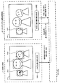
[第2の顔検出処理]
図9は、第2の顔検出処理の概要を説明するための図である。
図9に示す第2の顔検出処理では、顔検出回路14は、入力画像P2の全体から顔を検出し、その顔の全体が含まれる領域の情報を出力する(ステップS201)。また、プログラマブル信号処理回路15は、入力画像P2から、目、口、口唇、鼻、眉、メガネ、マスクなど、顔の内部および周囲のパーツ(以下、単に「顔のパーツ」と呼ぶ。)の位置や状態(パーツの向き、傾き、形状など)を検出する(ステップS202)。このとき、プログラマブル信号処理回路15は、入力画像P2のうち、顔検出回路14によって検出された顔領域のみ、またはその周囲を含む領域のみを、顔のパーツの探索領域とすることで、パーツ検出に要する時間を短縮する。
[Second face detection processing]
FIG. 9 is a diagram for explaining the outline of the second face detection process.
In the second face detection process shown in FIG. 9, the
さらに、顔検出回路14では、顔の座標やサイズだけでなく、その顔の向きや傾きを検出できるようにしてもよい。これらの情報を顔検出パラメータとしてプログラマブル信号処理回路15に設定するようにすれば、プログラマブル信号処理回路15では、顔のパーツの向き、傾き、位置の偏りなどをあらかじめ知ることができるので、より高速かつ高精度にパーツ検出を実行できるようになる。また、プログラマブル信号処理回路15は、顔のパーツの位置やその状態などの検出結果から、その顔の表情を評価した評価値を出力できるようにしてもよい。
Furthermore, the
図9の例では、顔検出回路14での検出処理により、入力画像P2から顔領域A21〜A23が検出されており、顔領域A21では顔の向きが矢印によって示され、顔領域A23では顔の傾きが一点鎖線によって示されている。また、これらの領域のうち、顔領域A22からは、プログラマブル信号処理回路15の処理により、顔のパーツとして目の領域A24およびA25と口の領域A26とが検出されている。
In the example of FIG. 9, the face areas A21 to A23 are detected from the input image P2 by the detection processing in the
なお、この第2の顔検出処理でも、第1の顔検出処理と同様に、顔検出回路14およびプログラマブル信号処理回路15において、同じ入力画像P2のデータを基に顔やパーツの検出処理が実行されることが望ましい。しかし実際の処理では、プログラマブル信号処理回路15では、顔検出回路14の検出対象の画像に対して1フレームまたは数フレーム分遅延した画像から検出が行われてもよい。
In the second face detection process, similarly to the first face detection process, the
図10は、撮像装置における第2の顔検出処理の流れを示すフローチャートである。
〔ステップS211〕CPU21は、顔検出回路14に対して顔検出パラメータを設定する。
FIG. 10 is a flowchart illustrating the flow of the second face detection process in the imaging apparatus.
[Step S211] The
〔ステップS212〕顔検出回路14のコントローラ44は、CPU21からの顔検出パラメータに応じて拡大・縮小回路41、画像メモリ42および顔検出コア43を制御し、画像RAM19から順次読み込んだ1フレーム分の画像データを基に、顔全体の領域を検出する処理を実行させる。
[Step S212] The
〔ステップS213〕顔検出回路14での顔検出処理が終了すると、顔検出コア43からCPU21に対して顔の検出結果(顔領域の座標、サイズ、向き、傾きなど)が出力される。
[Step S213] When the face detection process in the
〔ステップS214〕CPU21は、顔検出回路14から供給された検出結果を基に、プログラマブル信号処理回路15に対する顔検出パラメータを設定する。ここでは例えば、顔検出回路14によって検出された顔領域とその周囲のみを顔の探索範囲とするように、プログラマブル信号処理回路15に対して顔検出パラメータにより指示する。これとともに、その顔の向き、傾きなどの情報も通知する。
[Step S214] The
〔ステップS215〕プログラマブル信号処理回路15のコントローラ54は、CPU21からの顔検出パラメータに応じて、画像RAM19から読み込んだ画像データのうち、顔検出回路14で検出された顔領域およびその周囲に対応するデータのみをDSP52および53(またはこれらの一方)に転送し、顔のパーツの顔検出処理および表情評価処理を実行させる。
[Step S215] The controller 54 of the programmable
〔ステップS216〕プログラマブル信号処理回路15のコントローラ54は、DSP52および53から顔のパーツの検出結果や表情評価値を受け取り、CPU21に対して出力する。
[Step S216] The controller 54 of the programmable
〔ステップS217〕CPU21は、プログラマブル信号処理回路15からパーツ検出結果や表情評価値を基に最終的な顔の検出結果を生成する。
なお、ステップS214〜S216の処理を、顔検出回路14によって顔が検出された場合のみ実行してもよい。
[Step S217] The
Note that the processing in steps S214 to S216 may be executed only when a face is detected by the
〔ステップS218〕CPU21は、顔検出処理を終了するか否かを判断し、終了しない場合はステップS211に戻って、顔検出回路14による顔検出処理を再度実行させる。
[Step S218] The
以上の第2の顔検出処理では、顔検出回路14による顔領域の検出結果を基に、プログラマブル信号処理回路15において探索領域を限定して顔のパーツが検出されるので、プログラマブル信号処理回路15での処理時間が短縮され、顔のパーツの検出精度を維持しながらも検出処理を高速化できる。また、顔検出回路14により検出された顔の向きや傾きの情報を、プログラマブル信号処理回路15において制御パラメータとして使用できるようにすることで、プログラマブル信号処理回路15での検出処理が一層効率化され、処理速度を向上させることができる。
In the second face detection process described above, the programmable
また、プログラマブル信号処理回路15では、どのパーツを検出するか、そのパーツの位置、大きさ、状態などのうちどの情報を検出結果とするか、それらの検出結果に基づいてどんな表情を評価するかといったことを、CPU21からの制御パラメータや、あるいは実行するプログラムを変更することにより適宜変更できる。このような変更は、例えばユーザ操作による撮像モードの選択に応じて行ったり、撮像中の状況に応じて自動的に行うことができる。
In addition, the programmable
プログラマブル信号処理回路15では例えば、顔のパーツの状態から、笑顔や真剣な顔などの表情を判定したり、その度合いを評価することができる。このような判定・評価結果は、CPU21の制御により例えば、人物のポートレート撮像の際に、その人物の表情が笑顔になったときに自動的にシャッタを切る、あるいは、証明写真を撮像する際に笑っていない顔を自動的に撮像するといった制御に利用することができる。
For example, the programmable
また、CPU21の制御により、目の状態の検出結果からまばたきをしているか否かを判定し、撮像されているすべての人物がまばたきをしていないタイミングで自動的にシャッタを切るようにすることもできる。また、目の状態の検出結果から被写体の人物が注視している方向を推定し、撮像レンズを注視しているときにのみシャッタを切ることを可能とすることもできる。また、目の状態の検出結果から、いわゆる赤目の状態や眼球から光が反射している場合など、目の部分の色が好ましくない場合を検出して、シャッタ動作を制御する、あるいは撮像された画像の色補正を行うことも可能になる。
Further, the
また、口や口唇の部分の状態の検出結果から被写体の人物が発話しているか否かを判定し、発話している場合に自動的にマイクロフォンをオンにしたり、その判定結果をシャッタ動作のタイミング制御に利用することもできる。 In addition, it is determined whether or not the subject person is speaking from the detection result of the state of the mouth and lips, and when the speaker is speaking, the microphone is automatically turned on, or the determination result is used as the timing of the shutter operation. It can also be used for control.
このように、この撮像装置では、内部構成を変更することなく、付加価値の高い様々な機能を搭載できるようになり、低価格で高機能の商品が実現される。また、新製品の発売の際にも、基本構成を変えることなく柔軟に仕様を変更できるようになる。 As described above, in this imaging apparatus, various functions with high added value can be mounted without changing the internal configuration, and a high-performance product can be realized at a low price. In addition, when new products are released, the specifications can be changed flexibly without changing the basic configuration.
なお、この第2の顔検出処理においても、上記のフローチャートのように、顔検出回路14およびプログラマブル信号処理回路15での各顔検出処理を直列に実行するのではなく、これらを並列に実行してもよい。例えば、顔検出回路14において顔検出処理が実行されると、プログラマブル信号処理回路15ではその検出結果を基に、次のフレームの画像から顔検出処理を実行する。このとき、プログラマブル信号処理回路15での顔検出処理と同時に、顔検出回路14において同じフレームの画像からの顔検出処理を開始させるようにする。あるいは、顔検出回路14の方が短時間で処理できる場合には、顔検出回路14は、自身による顔検出処理の終了タイミングが、プログラマブル信号処理回路15での顔検出処理の終了タイミングに合うように、次以降のフレームからの顔検出処理を開始する。このような処理により、顔のパーツの検出結果を1フレームごとに確実に出力できるようになるとともに、その検出結果の精度を高めることができる。
In the second face detection process, the face detection processes in the
[第3の顔検出処理]
図11は、第3の顔検出処理の概要を説明するための図である。
図11に示す第3の顔検出処理では、顔検出回路14は、入力画像P3のデータのうち輝度情報のみから顔を検出する(ステップS301)。一方、プログラマブル信号処理回路15は、入力画像P3の中の肌色領域を示す情報を基に顔を検出する(ステップS302)。例えば、肌色の色相の領域を検出し、その領域またはその周囲を含む領域から、顔検出回路14とは異なる検出アルゴリズムにより顔を検出する。あるいは、検出した肌色領域自体を顔領域として検出してもよい。
[Third face detection processing]
FIG. 11 is a diagram for explaining the outline of the third face detection process.
In the third face detection process shown in FIG. 11, the
CPU21は、各ブロックからの検出結果を加味して最終的な顔領域を判定し(ステップS303)、これにより高精度な顔検出を実現する。例えば、顔検出回路14では、輝度情報のみを利用して顔を検出する構成とすることで処理速度を向上させることができるが、その反面、顔の誤検出や検出漏れが発生する場合があり得る。このような場合に、肌色領域の検出を基に顔をより正確に検出して、顔検出回路14での検出結果を補完することができる。
The
図11の例では、顔検出回路14により検出された顔領域A31では、肌の色と同じ明るさや模様の領域を顔であると誤検出している。しかし、プログラマブル信号処理回路15での顔検出により、顔領域A31が誤って検出されたものであることがわかり、この顔領域A31を最終的に検出結果から除去できる。また、プログラマブル信号処理回路15では顔領域A32が検出されているが、顔検出回路14ではこれに対応する領域からは顔が検出されていない。この領域では帽子により顔の一部が隠れているために、顔検出回路14において検出漏れが発生したと考えられるが、プログラマブル信号処理回路15での顔検出によりこのような検出漏れが防止される。
In the example of FIG. 11, in the face area A31 detected by the
以上の例では、一方の検出アルゴリズムの弱点を他方の検出アルゴリズムでの検出結果により補完しているが、互いの検出アルゴリズムの弱点を補完し合うようにCPU21が制御してもよい。さらに、CPU21は、各ブロックからの検出結果を基に、各ブロックに対する顔検出パラメータを再設定し、より効率よく顔検出が実行されるようにしてもよい。
In the above example, the weak point of one detection algorithm is complemented by the detection result of the other detection algorithm, but the
図12は、撮像装置における第3の顔検出処理の流れを示すフローチャートである。
〔ステップS311〕CPU21は、顔検出回路14に対して顔検出パラメータを設定する。
FIG. 12 is a flowchart showing a flow of third face detection processing in the imaging apparatus.
[Step S311] The
〔ステップS312〕顔検出回路14のコントローラ44は、CPU21からの顔検出パラメータに応じて拡大・縮小回路41、画像メモリ42および顔検出コア43を制御し、画像RAM19から順次読み込んだ1フレーム分の輝度情報を基に顔領域を検出する処理を実行させる。
[Step S312] The
〔ステップS313〕顔検出回路14での顔検出処理が終了すると、顔検出コア43からCPU21に対して顔の検出結果(顔領域の座標、サイズなど)が出力される。
〔ステップS314〕一方、CPU21は、ステップS311の処理と並行して、プログラマブル信号処理回路15に対して顔検出パラメータを設定する。
[Step S313] When the face detection processing in the
[Step S314] On the other hand, the
〔ステップS315〕プログラマブル信号処理回路15のコントローラ54は、CPU21からの顔検出パラメータに応じて、画像RAM19から読み込んだ画像データをDSP52および53(またはこれらの一方)に転送し、肌色領域に基づく顔検出処理を実行させる。
[Step S315] The controller 54 of the programmable
なお、上述したように、プログラマブル信号処理回路15では、例えば、入力画像の色成分から肌色の色相の領域を検出し、その領域またはその周囲を含む領域から、顔検出回路14とは異なる検出アルゴリズムにより顔を検出する。あるいは、その領域から顔検出回路14とは異なる信号成分(色差成分など)を基に顔を検出してもよい。
Note that, as described above, the programmable
また、肌色領域は、プログラマブル信号処理回路15ではなく、例えばカメラ信号処理回路13がホワイトバランス調整などのために従来から備えている検波機能により検波されてもよい。この場合、CPU21は、この検波機能により検出された肌色領域またはその周囲を含む領域を顔の探索領域とするように、プログラマブル信号処理回路15に指定する。
Further, the skin color area may be detected by a detection function that is conventionally provided in the camera
〔ステップS316〕プログラマブル信号処理回路15のコントローラ54は、DSP52および53から顔領域の検出結果を受け取り、CPU21に対して出力する。
〔ステップS317〕CPU21は、顔検出回路14およびプログラマブル信号処理回路15からの各検出結果を基に、最終的な検出結果を生成する。
[Step S316] The controller 54 of the programmable
[Step S317] The
〔ステップS318〕CPU21は、顔検出処理を終了するか否かを判断し、終了しない場合はステップS319の処理を実行する。
〔ステップS319〕CPU21は、顔検出回路14およびプログラマブル信号処理回路15からの各検出結果を基に、それぞれのブロックに対する顔検出パラメータを再計算する。この後、ステップS311およびS314に戻って、算出した顔検出パラメータを各ブロックに設定し、次の画像からの顔検出処理を開始させる。
[Step S318] The
[Step S319] The
以上のように、顔検出回路14およびプログラマブル信号処理回路15での顔検出処理は、それぞれ並列に実行され、それらの処理による検出結果を基にCPU21によって最終的な検出結果が得られる。これにより、一方のブロック、あるいは互いのブロックによる検出アルゴリズムの弱点をCPU21の処理により補完して、顔領域を正確に検出することができる。
As described above, the face detection processes in the
また、上記のフローチャートでは、顔検出回路14およびプログラマブル信号処理回路15での顔検出処理をそれぞれ1回ずつ並列に実行していたが、例えば顔検出回路14による処理の方が短時間で処理できる場合には、プログラマブル信号処理回路15が1フレーム分の顔検出処理を行う間に、顔検出回路14が複数フレーム分の顔検出処理を行うようにしてもよい。この場合、CPU21は例えば、顔検出回路14から検出結果が出力されるたびに、その検出結果と、プログラマブル信号処理回路15からの最新の検出結果とを基に最終的な検出結果を生成する。このような処理により、例えば動画像の記録時などにおいて、顔領域の検出結果を1フレームごとに確実に出力できるとともに、その検出結果の精度を高めることができる。
Further, in the above flowchart, the face detection processing in the
また、ステップS319での顔検出パラメータの再計算処理により、顔検出回路14およびプログラマブル信号処理回路15での顔検出処理を効率化することができる。例えば、プログラマブル信号処理回路15は、検出によって得られた顔領域の情報とともに肌色領域の情報をCPU21に出力するようにし、CPU21は、例えばその後の所定回数については入力画像から肌色領域を含む部分的な領域のみを顔の探索範囲とするように、プログラマブル信号処理回路15に対する顔検出パラメータを再計算する。これにより、プログラマブル信号処理回路15での処理時間を短縮することができる。なお、このような機能は、CPU21の制御ではなく、プログラマブル信号処理回路15で実行されている検出プログラムによって実現されていてもよい。
Further, the face detection processing in the
さらに例えば、顔検出回路14に対しても肌色領域を含む部分的な領域のみを顔の探索範囲とし、これとともに顔の検出精度を高めるように顔検出パラメータを再設定してもよい。この場合、顔検出回路14は例えば一定回数ごとに入力画像の全面から顔検出を行い、その間には肌色領域に基づく探索範囲のみから顔を検出する。このように、2つの処理ブロックで異なるアルゴリズムを用いて顔を検出したり、あるいは異なる画像成分を基に顔を検出する場合などには、一方のブロックの検出結果を他方のブロックでの顔検出処理に反映させることで、全体での検出速度を高めつつ、検出精度を向上させることができる。
Further, for example, only the partial area including the skin color area may be set as the face search range for the
また、上記の処理手順における顔検出回路14またはプログラマブル信号処理回路15での顔検出処理や、顔検出回路14に対する顔検出パラメータの再計算処理などを、撮像装置に設定される動作モードに応じて選択的に実行するようにしてもよい。
In addition, the face detection process in the
例えば、静止画像記録モードの場合、CPU21は、記録操作前に撮像されている画像をモニタに表示させ、ユーザが画角合わせをしている状態では、ステップS312,S313における顔検出回路14での顔検出処理のみを実行させて、その検出結果を基にAE、AFなどを制御する。これにより検出精度は劣るものの、画像を高速に表示でき、その間の消費電力も抑制できる。そして、例えばシャッタレリーズボタンが半押しされたときに、ステップS315,S316におけるプログラマブル信号処理回路15での顔検出処理も並列に実行して、各ブロックからの検出結果を基に正確な顔検出処理を行うようにしてもよい。さらに、動画像記録モードの場合には、ステップS319における顔検出回路14に対する顔検出パラメータの再計算処理を例えば一定時間ごとに実行して、顔の検出精度を維持しつつも全体の処理負荷を低下させ、所定のフレームレートでの画像記録を確実に実行できるようにしてもよい。
For example, in the still image recording mode, the
[第4の顔検出処理]
図13は、第4の顔検出処理の概要を説明するための図である。
第4の顔検出処理は、入力画像から特定の人物、あるいは特定の性質を持つ人物の顔を検出するものである。図13に示すように、顔検出回路14は、入力画像P4の全体から特に人物や性質などを特定せずに一般的な顔検出を行い、顔領域の座標やサイズ、顔の向き、傾きなどを出力する(ステップS401)。プログラマブル信号処理回路15は、入力画像P4から、特定の人物や特定の性質を持つ人物の顔を検出する(ステップS402)。このとき、プログラマブル信号処理回路15は、入力画像P4のうち、顔検出回路14によって検出された顔領域、またはその周囲を含む領域のみを顔の探索領域とすることで、顔検出に要する時間が短縮される。
[Fourth face detection process]
FIG. 13 is a diagram for explaining the outline of the fourth face detection process.
The fourth face detection process is to detect a face of a specific person or a person having a specific property from the input image. As shown in FIG. 13, the
図13の例では、顔検出回路14での一般的な顔の検出処理により、入力画像P4から顔領域A41〜A43が検出されている。また、プログラマブル信号処理回路15は、これらのうち顔領域A41に含まれる顔を、特定の人物のものと判定している。
In the example of FIG. 13, the face areas A41 to A43 are detected from the input image P4 by the general face detection process in the
また、顔検出回路14では、顔の座標やサイズだけでなく、その顔の向きや傾きを検出できるようにしてもよい。これらの情報を顔検出パラメータとしてプログラマブル信号処理回路15に設定するようにすれば、プログラマブル信号処理回路15では、顔のパーツの向き、傾き、位置の偏りなどをあらかじめ知ることができるので、より高速かつ高精度に顔検出を実行できるようになる。
Further, the
さらに、検出する人物や、その人物が持つ特定の性質については、ユーザ操作などによって選択できるようにしてもよい。この場合、次の図14でも説明するように、プログラマブル信号処理回路15において、それらの選択に応じた顔検出用データベース(例えば顔のテンプレートなどを含む)が切り替えられて用いられる。一方、顔検出回路14では、特定の人物やその性質などに依存しない一般的な顔を検出するためのデータベースのみが用いられる。
Further, the person to be detected and the specific property of the person may be selected by a user operation or the like. In this case, as will be described in FIG. 14, in the programmable
なお、この第4の顔検出処理でも、第1および第2の顔検出処理と同様に、顔検出回路14およびプログラマブル信号処理回路15において、同じ入力画像P4のデータを基に顔検出処理が実行されることが望ましい。しかし実際の処理では、プログラマブル信号処理回路15では、顔検出回路14の検出対象の画像に対して1フレームまたは数フレーム分遅延した画像から検出が行われてもよい。
In the fourth face detection process, as in the first and second face detection processes, the
図14は、撮像装置における第4の顔検出処理の流れを示すフローチャートである。
この図14の処理では、特定の性質を持つ顔を検出する場合の例として、女性の顔、乳幼児の顔、東洋人の顔のいずれかを、ユーザの選択操作に応じて検出できるようになっている。
FIG. 14 is a flowchart illustrating a flow of fourth face detection processing in the imaging apparatus.
In the process of FIG. 14, as an example of detecting a face having a specific property, any one of a female face, an infant's face, and an Oriental face can be detected according to a user's selection operation. ing.
〔ステップS411〕CPU21は、顔検出回路14に対して顔検出パラメータを設定する。
〔ステップS412〕顔検出回路14のコントローラ44は、CPU21からの顔検出パラメータに応じて拡大・縮小回路41、画像メモリ42および顔検出コア43を制御し、画像RAM19から順次読み込んだ1フレーム分の画像データを基に、一般的な顔を検出する処理を実行させる。
[Step S411] The
[Step S412] The
〔ステップS413〕顔検出回路14での顔検出処理が終了すると、顔検出コア43からCPU21に対して顔の検出結果(例えば顔領域の座標、サイズ、顔の向き、傾きなど)が出力される。
[Step S413] When the face detection process in the
〔ステップS414〕CPU21は、ユーザによってどのような性質を持つ顔を検出するように設定されているかを判断する。女性の顔を検出するように設定されている場合はステップS415の処理を実行する。乳幼児の顔を検出するように設定されている場合はステップS418の処理を実行する。東洋人の顔を検出するように設定されている場合はステップS421の処理を実行する。
[Step S414] The
〔ステップS415〕CPU21は、プログラマブル信号処理回路15に対して、女性の顔を検出するための顔検出パラメータを設定する。ここでは例えば、顔検出回路14によって検出された顔領域とその周囲のみを顔の探索範囲とするように、プログラマブル信号処理回路15に対して顔検出パラメータにより指示する。これとともに、その顔の向き、傾きなどの情報も通知する。さらに、女性の顔検出用データベースを設定する。このデータベースには、例えば女性の顔の特徴点の情報などが記録されている。
[Step S415] The
〔ステップS416〕プログラマブル信号処理回路15のコントローラ54は、CPU21からの顔検出パラメータに応じてDSP52および53を制御し、RAM51から順次読み込んだ1フレーム分の画像データを基に、女性の顔検出用データベースを用いた顔検出処理を実行させる。
Controller 5 4 [Step S416] A programmable
〔ステップS417〕プログラマブル信号処理回路15のコントローラ54は、DSP52および53から顔の検出結果を受け取り、CPU21に対して出力する。
〔ステップS418〜S420〕これらのステップの処理は、それぞれステップS415〜S417の処理とほぼ同じである。異なる点は、ステップS418において、CPU21が、乳幼児の顔検出用データベースを顔検出パラメータによりプログラマブル信号処理回路15に設定し、ステップS419において、プログラマブル信号処理回路15がこのデータベースを用いて顔検出を行う点である。
[Step S417] The controller 54 of the programmable
[Steps S418 to S420] The processes in these steps are substantially the same as those in steps S415 to S417, respectively. The difference is that in step S418, the
〔ステップS421〜S423〕これらのステップの処理は、それぞれステップS415〜S417の処理とほぼ同じである。異なる点は、ステップS421において、CPU21が、東洋人の顔検出用データベースを顔検出パラメータによりプログラマブル信号処理回路15に設定し、ステップS422において、プログラマブル信号処理回路15がこのデータベースを用いて顔検出を行う点である。
[Steps S421 to S423] The processing of these steps is substantially the same as the processing of steps S415 to S417, respectively. The difference is that in step S421, the
なお、上記のステップS415〜S423においては、例えば、女性、乳幼児、東洋人の顔の検出にそれぞれ特化した顔検出用データベースをあらかじめプログラマブル信号処理回路15のRAM51にロードしておき、どのデータベースを使用するかが顔検出パラメータによってCPU21からプログラマブル信号処理回路15に指示される。あるいは、ユーザ選択に応じた顔検出データベースが、CPU21の処理によりEEPROM22から読み出され、プログラマブル信号処理回路15にロードされてもよい。あるいは、ユーザ選択に応じた顔検出データベースが単に選択されるのではなく、検出対象とする顔の特性ごとに別の顔検出プログラムがプログラマブル信号処理回路15で実行されるようにしてもよい。
In steps S415 to S423 described above, for example, a face detection database specialized for detecting faces of women, infants, and Orientals is loaded in advance into the RAM 51 of the programmable
〔ステップS424〕CPU21は、プログラマブル信号処理回路15からの顔の検出結果を基に最終的な顔の検出結果(顔の座標、サイズなど)を生成する。
なお、ステップS414〜S424の処理を、顔検出回路14によって顔が検出された場合のみ実行してもよい。
[Step S424] The
Note that the processing of steps S414 to S424 may be executed only when a face is detected by the
〔ステップS425〕CPU21は、顔検出処理を終了するか否かを判断し、終了しない場合はステップS426の処理を実行する。
〔ステップS426〕CPU21は、プログラマブル信号処理回路15からの顔の検出結果を基に、顔検出回路14に対する顔検出パラメータを再計算する。この後、ステップS411に進んで、算出した顔検出パラメータを顔検出回路14に設定し、次の画像からの顔検出処理を開始させる。また、その後のステップS415,S418,S421のいずれかの処理では、ステップS426で算出した顔検出パラメータをプログラマブル信号処理回路15に対して設定する。
[Step S425] The
[Step S426] CPU21, based on the detection result of the face from the programmable
以上の第4の顔検出処理では、顔検出回路14による顔領域の検出結果を基に、プログラマブル信号処理回路15において探索領域を限定して顔が検出されるので、プログラマブル信号処理回路15での処理時間が短縮され、顔の検出精度を維持しながらも検出処理を高速化できる。また特に、顔検出回路14によりすでに顔が存在していると判定されている領域から、プログラマブル信号処理回路15においてより細かい検出が行われるので、処理負荷を高めることなく、より精度の高い顔検出を行うことが可能となる。
In the fourth face detection process described above, a face is detected by limiting the search area in the programmable
さらに、プログラマブル信号処理回路15では、ユーザによる設定に応じて、検出対象の人物や顔の性質などを変更できるので、この撮像装置の内部構成を変更することなく、機能性を高めることができる。また、同じ基本構成の回路によって、仕様の異なる様々な製品に応用できるようにもなり、多くの製品の開発・製造コストを抑制できる。
Furthermore, since the programmable
なお、この第4の顔検出処理においても、上記のフローチャートのように、顔検出回路14およびプログラマブル信号処理回路15での各顔検出処理を直列に実行するのではなく、これらを並列に実行してもよい。例えば、顔検出回路14において顔検出処理が実行されると、プログラマブル信号処理回路15ではその検出結果を基に、次のフレームの画像から顔検出処理を実行する。このとき、プログラマブル信号処理回路15での顔検出処理と同時に、顔検出回路14において同じフレームの画像からの顔検出処理を開始させるようにする。あるいは、顔検出回路14の方が短時間で処理できる場合には、顔検出回路14は、自身による顔検出処理の終了タイミングが、プログラマブル信号処理回路15での顔検出処理の終了タイミングに合うように、次以降のフレームからの顔検出処理を開始する。このような処理により、特定の人物や特定の性質を持つ顔の検出結果を1フレームごとに確実に出力できるようになるとともに、その検出結果の精度を高めることができる。
In the fourth face detection process, the face detection processes in the
[他の実施の形態]
図15は、本発明の他の実施の形態に係る画像記録再生装置の構成を示すブロック図である。なお、この図15では、図1に対応するブロックには同じ符号を付して示している。
[Other embodiments]
FIG. 15 is a block diagram showing a configuration of an image recording / reproducing apparatus according to another embodiment of the present invention. In FIG. 15, the blocks corresponding to those in FIG.
本発明は、上述したような撮像装置だけでなく、図15に示すような撮像機能を持たない画像記録再生装置に対して適用することもできる。この画像記録再生装置は、例えばビデオレコーダなどとして実現される。この場合、テレビ放送の受信信号などから得た動画像データが、画像バス20を介して画像圧縮・伸張回路17に入力されて圧縮符号化されて、動画像ファイルとして記憶装置18に記憶される。また、このような動画像ファイルを記憶装置18から読み出して、画像圧縮・伸張回路17によって伸張復号化した後、画像処理回路25によって例えば各種の画質補正処理を施し、表示処理回路16に出力することで、画質補正後の再生画像を図示しないモニタに表示することができる。
The present invention can be applied not only to the imaging apparatus as described above but also to an image recording / reproducing apparatus having no imaging function as shown in FIG. This image recording / reproducing apparatus is realized as a video recorder, for example. In this case, moving image data obtained from a television broadcast reception signal or the like is input to the image compression / decompression circuit 17 via the
このような動画像再生時において、伸張復号化された画像データを、画像RAM19を介して顔検出回路14およびプログラマブル信号処理回路15に供給して、上述した各顔検出処理手順により再生画像から顔を検出することができる。顔の検出結果は、例えば、検出された顔の部分の色がより適切になるように、画像全体の色を画像処理回路25で補正するなどの用途に用いることができる。
At the time of such moving image reproduction, the decompressed and decoded image data is supplied to the
このような画像記録再生装置においても、上記の顔検出処理手順で説明したように、高速かつ高精度な顔の検出を行うことが可能になる。また、顔の検出結果の使用目的や、必要な検出精度、検出情報などに応じて、プログラマブル信号処理回路15での検出処理手順や検出設定を柔軟に変化させることができる。
Even in such an image recording / reproducing apparatus, it is possible to detect a face with high speed and high accuracy as described in the face detection processing procedure. Moreover, the detection processing procedure and detection setting in the programmable
なお、この例では記憶媒体に画像を記録できる装置としたが、例えば可搬型の記憶媒体に記憶された画像データを再生するビデオプレーヤに本発明を適用することもできる。また、他の撮像機器において撮像された、あるいはネットワークを介して受信した画像ファイルを一旦記憶装置18に蓄積し、その画像ファイルを再生可能な再生機器に本発明を適用することもできる。さらに例えば、他の機器から画像ファイルの供給を受けてその再生画像を印刷するプリンタなどにも、本発明を適用することができる。
In this example, the apparatus can record an image on a storage medium. However, the present invention can also be applied to, for example, a video player that reproduces image data stored on a portable storage medium. In addition, the present invention can be applied to a playback device that can temporarily store an image file captured by another imaging device or received via a network in the
11……光学ブロック、12……イメージセンサ、13……カメラ信号処理回路、14……顔検出回路、15……プログラマブル信号処理回路、16……表示処理回路、17……画像圧縮・伸張回路、18……記憶装置、19……画像RAM、20……画像バス、21……CPU、22……EEPROM、23,51……RAM、24……重力方向センサ、41……拡大・縮小回路、42……画像メモリ、43……顔検出コア、44,54……コントローラ、52,53……DSP
DESCRIPTION OF SYMBOLS 11 ... Optical block, 12 ... Image sensor, 13 ... Camera signal processing circuit, 14 ... Face detection circuit, 15 ... Programmable signal processing circuit, 16 ... Display processing circuit, 17 ... Image compression / decompression circuit , 18 ... storage device, 19 ... image RAM, 20 ... image bus, 21 ... CPU, 22 ... EEPROM, 23, 51 ... RAM, 24 ... gravity direction sensor, 41 ... enlargement / reduction circuit , 42 ... Image memory, 43 ... Face detection core, 44, 54 ... Controller, 52, 53 ... DSP
Claims (18)
入力画像からの顔検出に特化したハードウェア回路からなる顔検出回路と、
入力画像から顔を検出するための顔検出プログラムを含む書き換え可能なプログラムに従って、入力画像信号を基に信号処理を実行する信号処理回路と、
前記顔検出回路および前記信号処理回路のそれぞれに、同じフレームの画像または連続したうちの近傍のフレームの画像からの顔検出処理を実行させる制御部と、
を有し、
前記制御部は、前記顔検出回路により検出された顔の領域を含む画像内の部分的な領域を、前記信号処理回路における顔検出領域として設定し、
前記信号処理回路は、当該設定された顔検出領域のみから顔を検出することを特徴とする顔検出装置。 In a face detection device for detecting a human face from an input image,
A face detection circuit comprising a hardware circuit specialized for face detection from an input image;
A signal processing circuit that executes signal processing based on an input image signal according to a rewritable program including a face detection program for detecting a face from the input image;
A control unit that causes each of the face detection circuit and the signal processing circuit to perform face detection processing from an image of the same frame or an image of a neighboring frame among consecutive ones;
I have a,
The control unit sets a partial area in the image including the face area detected by the face detection circuit as a face detection area in the signal processing circuit;
The face detection device , wherein the signal processing circuit detects a face only from the set face detection area .
前記信号処理回路は、顔の誤検出を防止することを優先した顔検出処理を実行することを特徴とする請求項1記載の顔検出装置。 The face detection circuit executes face detection processing prioritizing prevention of face detection omission,
The signal processing circuit includes a face detecting device according to claim 1, wherein the performing the face detection processing priority to prevent erroneous detection of the face.
前記制御部は、前記信号処理回路により検出された顔の方向を基に、前記顔検出回路による次の入力画像における顔検出領域を設定することを特徴とする請求項4記載の顔検出装置。 The signal processing circuit detects a face from the face detection area set by the control unit and detects the face direction,
5. The face detection apparatus according to claim 4 , wherein the control unit sets a face detection area in a next input image by the face detection circuit based on a face direction detected by the signal processing circuit .
前記信号処理回路は、特定の人物の顔の検出処理を実行することを特徴とする請求項1記載の顔検出装置。 The face detection circuit performs a general face detection process,
The signal processing circuit includes a face detecting device according to claim 1, wherein the executing the detection processing of the face of a specific person.
前記信号処理回路は、特定の性質を持つ顔の検出処理を実行することを特徴とする請求項1記載の顔検出装置。 The face detection circuit performs a general face detection process,
The signal processing circuit includes a face detecting device according to claim 1, wherein the performing the detection process of the face with specific properties.
入力画像からの顔検出に特化したハードウェア回路からなる顔検出回路と、
入力画像から顔を検出するための顔検出プログラムを含む書き換え可能なプログラムに従って、入力画像信号を基に信号処理を実行する信号処理回路と、
前記顔検出回路および前記信号処理回路のそれぞれに、撮像によって連続的に得られた画像のうちの同じフレームの画像または近傍のフレームの画像からの顔検出処理を実行させる制御部と、
を有し、
前記制御部は、前記顔検出回路により検出された顔の領域を含む画像内の部分的な領域を、前記信号処理回路における顔検出領域として設定し、
前記信号処理回路は、当該設定された顔検出領域のみから顔を検出することを特徴とする撮像装置。 In an imaging device that captures an image using a solid-state imaging device,
A face detection circuit comprising a hardware circuit specialized for face detection from an input image;
A signal processing circuit that executes signal processing based on an input image signal according to a rewritable program including a face detection program for detecting a face from the input image;
A control unit that causes each of the face detection circuit and the signal processing circuit to perform face detection processing from an image of the same frame or an image of a nearby frame among images continuously obtained by imaging;
I have a,
The control unit sets a partial area in the image including the face area detected by the face detection circuit as a face detection area in the signal processing circuit;
The image processing apparatus, wherein the signal processing circuit detects a face only from the set face detection area .
顔検出に特化したハードウェア回路からなる顔検出回路が、入力画像から顔を検出し、
顔を検出するための顔検出プログラムを含む書き換え可能なプログラムに従って入力画像信号を基に信号処理を実行する信号処理回路が、前記顔検出プログラムを実行することで、前記顔検出回路への入力と同じフレームの画像または連続したうちの近傍のフレームの画像から顔を検出する、
処理を含み、
前記信号処理回路による顔検出処理では、前記顔検出回路により検出された顔の領域を含む画像内の部分的な領域を、顔検出領域として設定することを特徴とする顔検出方法。 In a face detection method for detecting a human face from an input image,
A face detection circuit consisting of a hardware circuit specialized for face detection detects a face from the input image,
By signal processing circuit for performing signal processing based on the input image signal in accordance with a rewritable program including a face detection program for detecting a face, it executes the face detection program, the input to the pre-Symbol face detection circuit Detect faces from images in the same frame or images in nearby frames
Including processing,
In the face detection process by the signal processing circuit, a partial area in an image including a face area detected by the face detection circuit is set as a face detection area .
Priority Applications (8)
| Application Number | Priority Date | Filing Date | Title |
|---|---|---|---|
| JP2006212841A JP4218711B2 (en) | 2006-08-04 | 2006-08-04 | Face detection device, imaging device, and face detection method |
| US11/888,322 US8116536B2 (en) | 2006-08-04 | 2007-07-31 | Face detection device, imaging apparatus, and face detection method |
| KR1020070077381A KR101421716B1 (en) | 2006-08-04 | 2007-08-01 | Face detection device, imaging apparatus and face detection method |
| TW096128457A TW200821983A (en) | 2006-08-04 | 2007-08-02 | Face detection device, imaging apparatus and face detection method |
| TW101101390A TW201246119A (en) | 2006-08-04 | 2007-08-02 | Face detector, image pickup device, and face detecting method |
| CN2007101401220A CN101159011B (en) | 2006-08-04 | 2007-08-06 | Face detection device, imaging apparatus and face detection method |
| US13/344,191 US9495578B2 (en) | 2006-08-04 | 2012-01-05 | Face detection device, imaging apparatus and face detection method |
| US15/288,794 US10037455B2 (en) | 2006-08-04 | 2016-10-07 | Face detection device, imaging apparatus, and face detection method |
Applications Claiming Priority (1)
| Application Number | Priority Date | Filing Date | Title |
|---|---|---|---|
| JP2006212841A JP4218711B2 (en) | 2006-08-04 | 2006-08-04 | Face detection device, imaging device, and face detection method |
Publications (2)
| Publication Number | Publication Date |
|---|---|
| JP2008040709A JP2008040709A (en) | 2008-02-21 |
| JP4218711B2 true JP4218711B2 (en) | 2009-02-04 |
Family
ID=39151606
Family Applications (1)
| Application Number | Title | Priority Date | Filing Date |
|---|---|---|---|
| JP2006212841A Expired - Fee Related JP4218711B2 (en) | 2006-08-04 | 2006-08-04 | Face detection device, imaging device, and face detection method |
Country Status (5)
| Country | Link |
|---|---|
| US (3) | US8116536B2 (en) |
| JP (1) | JP4218711B2 (en) |
| KR (1) | KR101421716B1 (en) |
| CN (1) | CN101159011B (en) |
| TW (2) | TW201246119A (en) |
Families Citing this family (29)
| Publication number | Priority date | Publication date | Assignee | Title |
|---|---|---|---|---|
| DE10211981B4 (en) * | 2002-03-18 | 2004-02-12 | Mediasec Technologies Gmbh | Process for increasing the information density of a bar code, as well as bar code |
| KR100840023B1 (en) * | 2007-11-13 | 2008-06-20 | (주)올라웍스 | Method and system for adjusting pose at the time of taking photos of himself or herself |
| JP4720880B2 (en) * | 2008-09-04 | 2011-07-13 | ソニー株式会社 | Image processing apparatus, imaging apparatus, image processing method, and program |
| JP2010068030A (en) * | 2008-09-08 | 2010-03-25 | Panasonic Corp | Image processing apparatus, image processing method, image processing program and imaging apparatus |
| US9514355B2 (en) | 2009-01-05 | 2016-12-06 | Apple Inc. | Organizing images by correlating faces |
| US9495583B2 (en) | 2009-01-05 | 2016-11-15 | Apple Inc. | Organizing images by correlating faces |
| US8548257B2 (en) * | 2009-01-05 | 2013-10-01 | Apple Inc. | Distinguishing between faces and non-faces |
| US8385638B2 (en) * | 2009-01-05 | 2013-02-26 | Apple Inc. | Detecting skin tone in images |
| JP5066133B2 (en) * | 2009-05-20 | 2012-11-07 | 株式会社日立製作所 | Information recording apparatus and power saving method |
| US8493453B2 (en) * | 2009-06-05 | 2013-07-23 | Apple Inc. | Image capturing devices using orientation detectors to implement automatic exposure mechanisms |
| JP5517504B2 (en) * | 2009-06-29 | 2014-06-11 | キヤノン株式会社 | Image processing apparatus, image processing method, and program |
| TWI423147B (en) * | 2009-07-22 | 2014-01-11 | Altek Corp | Photographing system capable of preventing from taking blink eye image and the method thereof |
| JP5218345B2 (en) * | 2009-09-02 | 2013-06-26 | 三菱電機株式会社 | Image detection device |
| JP5336995B2 (en) * | 2009-10-19 | 2013-11-06 | キヤノン株式会社 | Feature point positioning device, image recognition device, processing method thereof, and program |
| JP2011090569A (en) * | 2009-10-23 | 2011-05-06 | Sony Corp | Image processing apparatus and image processing method |
| US9536046B2 (en) * | 2010-01-12 | 2017-01-03 | Microsoft Technology Licensing, Llc | Automated acquisition of facial images |
| JP5499796B2 (en) * | 2010-03-15 | 2014-05-21 | 株式会社ニコン | Electronics |
| US8726161B2 (en) * | 2010-10-19 | 2014-05-13 | Apple Inc. | Visual presentation composition |
| EP2676222B1 (en) * | 2011-02-18 | 2018-09-19 | Google LLC | Facial recognition |
| US9552376B2 (en) | 2011-06-09 | 2017-01-24 | MemoryWeb, LLC | Method and apparatus for managing digital files |
| JP2013074570A (en) * | 2011-09-29 | 2013-04-22 | Sanyo Electric Co Ltd | Electronic camera |
| KR101289087B1 (en) * | 2011-11-03 | 2013-08-07 | 인텔 코오퍼레이션 | Face detection method, apparatus, and computer-readable recording medium for executing the method |
| KR101279561B1 (en) * | 2012-01-19 | 2013-06-28 | 광운대학교 산학협력단 | A fast and accurate face detection and tracking method by using depth information |
| WO2013186906A1 (en) | 2012-06-14 | 2013-12-19 | トヨタ自動車株式会社 | Discrimination container generation device and pattern detection device |
| JP6181925B2 (en) * | 2012-12-12 | 2017-08-16 | キヤノン株式会社 | Image processing apparatus, image processing apparatus control method, and program |
| JP5623589B2 (en) * | 2013-05-07 | 2014-11-12 | キヤノン株式会社 | IMAGING DEVICE AND IMAGING DEVICE CONTROL METHOD |
| KR102415503B1 (en) | 2015-08-21 | 2022-07-01 | 삼성전자주식회사 | Method for training classifier and detecting object |
| US10936178B2 (en) | 2019-01-07 | 2021-03-02 | MemoryWeb, LLC | Systems and methods for analyzing and organizing digital photos and videos |
| JP2021136671A (en) * | 2020-02-28 | 2021-09-13 | キヤノン株式会社 | Information processing device, imaging device, method, program and storage medium |
Family Cites Families (20)
| Publication number | Priority date | Publication date | Assignee | Title |
|---|---|---|---|---|
| JP3017384B2 (en) * | 1993-07-19 | 2000-03-06 | シャープ株式会社 | Feature region extraction device |
| JP3490482B2 (en) | 1993-09-20 | 2004-01-26 | 株式会社東芝 | Edge and contour extraction device |
| JP3561985B2 (en) | 1994-11-28 | 2004-09-08 | ソニー株式会社 | Image processing device |
| JP2003058516A (en) | 2001-08-21 | 2003-02-28 | Toshiba Corp | Method and device for signal processing |
| US7113637B2 (en) * | 2001-08-24 | 2006-09-26 | Industrial Technology Research Institute | Apparatus and methods for pattern recognition based on transform aggregation |
| US7050607B2 (en) * | 2001-12-08 | 2006-05-23 | Microsoft Corp. | System and method for multi-view face detection |
| JP2003271933A (en) | 2002-03-18 | 2003-09-26 | Sony Corp | Face detector, face detecting method, and robot device |
| JP2004005384A (en) | 2002-04-19 | 2004-01-08 | Sony Corp | Image processing method, image processing device, program, recording medium, automatic trimming device and picture-taking arrangement |
| JP4329398B2 (en) | 2002-05-10 | 2009-09-09 | ソニー株式会社 | Face detection apparatus and method, program, and recording medium |
| WO2004004320A1 (en) * | 2002-07-01 | 2004-01-08 | The Regents Of The University Of California | Digital processing of video images |
| GB2395778A (en) * | 2002-11-29 | 2004-06-02 | Sony Uk Ltd | Face detection |
| US7242423B2 (en) * | 2003-06-16 | 2007-07-10 | Active Eye, Inc. | Linking zones for object tracking and camera handoff |
| JP4743823B2 (en) | 2003-07-18 | 2011-08-10 | キヤノン株式会社 | Image processing apparatus, imaging apparatus, and image processing method |
| EP2955662B1 (en) * | 2003-07-18 | 2018-04-04 | Canon Kabushiki Kaisha | Image processing device, imaging device, image processing method |
| US7450735B1 (en) * | 2003-10-16 | 2008-11-11 | University Of Central Florida Research Foundation, Inc. | Tracking across multiple cameras with disjoint views |
| US20050281464A1 (en) * | 2004-06-17 | 2005-12-22 | Fuji Photo Film Co., Ltd. | Particular image area partitioning apparatus and method, and program for causing computer to perform particular image area partitioning processing |
| JP4574249B2 (en) * | 2004-06-29 | 2010-11-04 | キヤノン株式会社 | Image processing apparatus and method, program, and imaging apparatus |
| JP2006050411A (en) * | 2004-08-06 | 2006-02-16 | Rohm Co Ltd | Semiconductor device |
| JP2006115406A (en) | 2004-10-18 | 2006-04-27 | Omron Corp | Imaging apparatus |
| US8542928B2 (en) * | 2005-09-26 | 2013-09-24 | Canon Kabushiki Kaisha | Information processing apparatus and control method therefor |
-
2006
- 2006-08-04 JP JP2006212841A patent/JP4218711B2/en not_active Expired - Fee Related
-
2007
- 2007-07-31 US US11/888,322 patent/US8116536B2/en not_active Expired - Fee Related
- 2007-08-01 KR KR1020070077381A patent/KR101421716B1/en active IP Right Grant
- 2007-08-02 TW TW101101390A patent/TW201246119A/en not_active IP Right Cessation
- 2007-08-02 TW TW096128457A patent/TW200821983A/en not_active IP Right Cessation
- 2007-08-06 CN CN2007101401220A patent/CN101159011B/en not_active Expired - Fee Related
-
2012
- 2012-01-05 US US13/344,191 patent/US9495578B2/en active Active
-
2016
- 2016-10-07 US US15/288,794 patent/US10037455B2/en active Active
Also Published As
| Publication number | Publication date |
|---|---|
| TWI380233B (en) | 2012-12-21 |
| US20170024606A1 (en) | 2017-01-26 |
| TWI380232B (en) | 2012-12-21 |
| US8116536B2 (en) | 2012-02-14 |
| US10037455B2 (en) | 2018-07-31 |
| US20120114179A1 (en) | 2012-05-10 |
| JP2008040709A (en) | 2008-02-21 |
| US9495578B2 (en) | 2016-11-15 |
| CN101159011B (en) | 2011-08-10 |
| TW200821983A (en) | 2008-05-16 |
| KR101421716B1 (en) | 2014-07-22 |
| CN101159011A (en) | 2008-04-09 |
| US20080056580A1 (en) | 2008-03-06 |
| KR20080012770A (en) | 2008-02-12 |
| TW201246119A (en) | 2012-11-16 |
Similar Documents
| Publication | Publication Date | Title |
|---|---|---|
| JP4218711B2 (en) | Face detection device, imaging device, and face detection method | |
| JP4218712B2 (en) | Face detection device, imaging device, and face detection method | |
| JP4973098B2 (en) | Image processing apparatus, image processing method, and program | |
| JP4626493B2 (en) | Image processing apparatus, image processing method, program for image processing method, and recording medium recording program for image processing method | |
| US20080284867A1 (en) | Image pickup apparatus with a human face detecting function, method and program product for detecting a human face | |
| US8988545B2 (en) | Digital photographing apparatus and method of controlling the same | |
| JP2011166442A (en) | Imaging device | |
| JP2006293782A (en) | Image processing device and image processing program | |
| JP5504990B2 (en) | Imaging apparatus, image processing apparatus, and program | |
| JP2009124644A (en) | Image processing device, imaging device, and image reproduction device | |
| US20240070877A1 (en) | Image processing apparatus, method for controlling the same, imaging apparatus, and storage medium | |
| JP4773924B2 (en) | IMAGING DEVICE, ITS CONTROL METHOD, PROGRAM, AND STORAGE MEDIUM | |
| JP5106364B2 (en) | Camera, control method and control program | |
| JP2009130840A (en) | Imaging apparatus, control method thereof ,and program | |
| JP2009010546A (en) | Imaging apparatus and specified image detection program | |
| JP2008109503A (en) | Imaging apparatus, control method thereof, program and storage medium | |
| JP2008109395A (en) | Imaging apparatus, image processing method, program, and storage medium | |
| JP2010136214A (en) | Camera, and method and program for controlling the same | |
| JP2013201662A (en) | Image reproduction device and imaging device | |
| JP2010044506A (en) | Image processor and image processing program |
Legal Events
| Date | Code | Title | Description |
|---|---|---|---|
| A977 | Report on retrieval |
Free format text: JAPANESE INTERMEDIATE CODE: A971007 Effective date: 20080707 |
|
| A131 | Notification of reasons for refusal |
Free format text: JAPANESE INTERMEDIATE CODE: A131 Effective date: 20080722 |
|
| A521 | Request for written amendment filed |
Free format text: JAPANESE INTERMEDIATE CODE: A523 Effective date: 20080922 |
|
| TRDD | Decision of grant or rejection written | ||
| A01 | Written decision to grant a patent or to grant a registration (utility model) |
Free format text: JAPANESE INTERMEDIATE CODE: A01 Effective date: 20081021 |
|
| A01 | Written decision to grant a patent or to grant a registration (utility model) |
Free format text: JAPANESE INTERMEDIATE CODE: A01 |
|
| A61 | First payment of annual fees (during grant procedure) |
Free format text: JAPANESE INTERMEDIATE CODE: A61 Effective date: 20081103 |
|
| FPAY | Renewal fee payment (event date is renewal date of database) |
Free format text: PAYMENT UNTIL: 20111121 Year of fee payment: 3 |
|
| R151 | Written notification of patent or utility model registration |
Ref document number: 4218711 Country of ref document: JP Free format text: JAPANESE INTERMEDIATE CODE: R151 |
|
| FPAY | Renewal fee payment (event date is renewal date of database) |
Free format text: PAYMENT UNTIL: 20111121 Year of fee payment: 3 |
|
| FPAY | Renewal fee payment (event date is renewal date of database) |
Free format text: PAYMENT UNTIL: 20111121 Year of fee payment: 3 |
|
| FPAY | Renewal fee payment (event date is renewal date of database) |
Free format text: PAYMENT UNTIL: 20121121 Year of fee payment: 4 |
|
| R250 | Receipt of annual fees |
Free format text: JAPANESE INTERMEDIATE CODE: R250 |
|
| FPAY | Renewal fee payment (event date is renewal date of database) |
Free format text: PAYMENT UNTIL: 20121121 Year of fee payment: 4 |
|
| FPAY | Renewal fee payment (event date is renewal date of database) |
Free format text: PAYMENT UNTIL: 20131121 Year of fee payment: 5 |
|
| R250 | Receipt of annual fees |
Free format text: JAPANESE INTERMEDIATE CODE: R250 |
|
| R250 | Receipt of annual fees |
Free format text: JAPANESE INTERMEDIATE CODE: R250 |
|
| R250 | Receipt of annual fees |
Free format text: JAPANESE INTERMEDIATE CODE: R250 |
|
| R250 | Receipt of annual fees |
Free format text: JAPANESE INTERMEDIATE CODE: R250 |
|
| R250 | Receipt of annual fees |
Free format text: JAPANESE INTERMEDIATE CODE: R250 |
|
| R250 | Receipt of annual fees |
Free format text: JAPANESE INTERMEDIATE CODE: R250 |
|
| R250 | Receipt of annual fees |
Free format text: JAPANESE INTERMEDIATE CODE: R250 |
|
| R250 | Receipt of annual fees |
Free format text: JAPANESE INTERMEDIATE CODE: R250 |
|
| R250 | Receipt of annual fees |
Free format text: JAPANESE INTERMEDIATE CODE: R250 |
|
| LAPS | Cancellation because of no payment of annual fees |