JP4743823B2 - Image processing apparatus, imaging apparatus, and image processing method - Google Patents
Image processing apparatus, imaging apparatus, and image processing method Download PDFInfo
- Publication number
- JP4743823B2 JP4743823B2 JP2004167588A JP2004167588A JP4743823B2 JP 4743823 B2 JP4743823 B2 JP 4743823B2 JP 2004167588 A JP2004167588 A JP 2004167588A JP 2004167588 A JP2004167588 A JP 2004167588A JP 4743823 B2 JP4743823 B2 JP 4743823B2
- Authority
- JP
- Japan
- Prior art keywords
- image
- face
- feature
- unit
- facial expression
- Prior art date
- Legal status (The legal status is an assumption and is not a legal conclusion. Google has not performed a legal analysis and makes no representation as to the accuracy of the status listed.)
- Expired - Fee Related
Links
Images


Description
本発明は、入力した画像中の顔などの被写体のカテゴリに係る判別を行う技術に関するものである。 The present invention relates to a technique for performing determination related to a category of a subject such as a face in an input image.
従来より、画像認識や音声認識の分野においては、特定の認識対象に特化した認識処理アルゴリズムを、コンピュータソフト、或いは専用並列画像処理プロセッサを用いたハードウェアにより実現することで、認識対象を検出するものが知られている。 Conventionally, in the field of image recognition and voice recognition, recognition processing algorithms specialized for a specific recognition target are realized by computer software or hardware using a dedicated parallel image processing processor to detect the recognition target. What to do is known.
特に、顔を含む画像から、この顔を特定の認識対象として検出するものとしては、従来からいくつかの文献が開示されている(例えば特許文献1乃至5を参照)。
In particular, several documents have been disclosed for detecting a face as a specific recognition target from an image including the face (see, for example,
そのうちの1つの技術によると、入力画像に対して、標準顔と呼ばれるテンプレートを使って、顔領域を探索し、その後、眼、鼻孔、口といった特徴点候補に対して、部分テンプレートを使用して、人物を認証する。しかしこの技術では、始めにテンプレートを使用して顔全体でマッチングして、顔領域を検出するため、複数の顔のサイズや、顔の向きの変化に弱く、それに対応するためには、サイズや顔の向きに対応した複数の標準顔を用意し、それぞれを用いて検出する必要があるが、顔全体のテンプレートはサイズも大きく、処理コストもかかる。 According to one of the techniques, a face area is searched for a template using a standard face for an input image, and then a partial template is used for candidate feature points such as eyes, nostrils, and mouth. Authenticate a person. However, this technology uses a template first to match the entire face to detect the face area, so it is vulnerable to changes in the size of multiple faces and face orientations. It is necessary to prepare a plurality of standard faces corresponding to the orientation of the face and detect them using each of them. However, the template for the entire face is large in size and processing cost.
またその他の技術によると、顔画像から眼と口候補群を求め、それらを組み合わせた顔候補群と予め記憶してある顔構造とを照合し、眼と口に対応する領域を発見する。この技術にでは、入力画像中の顔の数は1つもしくは少数であり、また顔の大きさもある程度大きなサイズであり、入力画像中のほとんどの領域は顔であり、背景は少ない画像が入力画像として想定されている。 According to another technique, an eye and mouth candidate group is obtained from a face image, and a face candidate group obtained by combining them and a previously stored face structure are collated to find a region corresponding to the eye and mouth. In this technique, the number of faces in the input image is one or a small number, the size of the face is also somewhat large, most of the areas in the input image are faces, and an image with a small background is the input image. Is assumed.
またその他の技術によると、眼、鼻、口候補をそれぞれ複数求め、予め用意されている特徴点間の位置関係から、顔を検出する。 According to another technique, a plurality of eye, nose, and mouth candidates are obtained, and a face is detected from the positional relationship between feature points prepared in advance.
またその他の技術によると、顔の各部品の形状データと入力画像との一致度を調べる際に、形状データを変更させるものであり、また各顔部品の探索領域は、以前に求めた部品の位置関係を基に決定するものである。この技術では、虹彩、口、鼻等の形状データを保持しておき、まず2つの虹彩を求め、続いて口、鼻等を求める際に、その虹彩の位置に基づいて、口、鼻等の顔部品の探索領域を限定している。つまり、このアルゴリズムは、虹彩(眼)、口、鼻といった顔を構成する顔部品を並列的に検出するのではなく、虹彩(眼)を最初に見つけ、その結果を使用して、順に口、鼻という顔部品を検出している。この方法では、画像中に顔が一つしかなく、さらに虹彩が正確に求まった場合を想定しており、検出された虹彩が誤検出であった場合には、口や鼻等の他の特徴の探索領域を正しく設定出来ない。 According to another technique, when examining the degree of coincidence between the shape data of each part of the face and the input image, the shape data is changed, and the search area of each face part is the previously determined part. It is determined based on the positional relationship. In this technique, the shape data of the iris, mouth, nose, etc. are stored, and first two irises are obtained, and then when the mouth, nose, etc. are obtained, the mouth, nose, etc. are determined based on the position of the iris. The search area for facial parts is limited. In other words, this algorithm does not detect the facial parts that make up the face such as the iris (eye), mouth, and nose in parallel, but first finds the iris (eye) and uses the result to It detects a facial part called the nose. In this method, it is assumed that there is only one face in the image and the iris is obtained accurately. If the detected iris is a false detection, other features such as mouth and nose The search area cannot be set correctly.
またその他の技術によると、複数の判定要素取得領域を設定した領域モデルを入力画像中で移動させ、各点で、それら判定要素取得領域内で、判定要素の有無を判定し、顔を認識するものである。この技術において、サイズの異なった顔や回転した顔に対応させるためには、サイズの異なった領域モデルや回転した領域モデルを用意する必要があるが、実際にそのサイズの顔やその回転角度の顔が存在しない場合、無駄な計算を多数行なう事となる。 According to another technique, an area model in which a plurality of determination element acquisition areas are set is moved in the input image, and at each point, the presence / absence of the determination element is determined in the determination element acquisition area to recognize the face. Is. In this technology, in order to correspond to faces of different sizes and rotated faces, it is necessary to prepare area models of different sizes and rotated area models. When there is no face, many unnecessary calculations are performed.
また、画像中の顔の表情を認識する手法もまた従来からいくつか開示されている(例えば非特許文献1、2を参照)。
In addition, some techniques for recognizing facial expressions in images have also been disclosed (see Non-Patent
そのうちの1つの技術では、目視によってフレーム画像から顔の部分領域が正確に切り出されることが前提となっている。またその他の技術でも、顔パターンの大まかな位置決めの自動化はされているが、特徴点の位置決めに当たっては人間の目視による微調整が必要となっている。また他の技術(例えば、特許文献6を参照)では、表情の要素を筋肉の動きや神経系接続関係等を用いてコード化し、情緒を決定する。ただしこの技術では、表情の認識に必要な部位の領域は固定されており、顔の向きの変化や動きによって、認識に必要な領域が含まれない可能性、逆に不要な領域が含まれてしまう可能性があり、表情の認識の精度に影響を及ぼすと考えられる。 One of the techniques is based on the premise that a partial face region is accurately cut out from a frame image by visual observation. In other techniques, the rough positioning of the face pattern is automated, but fine positioning by human visual inspection is necessary for positioning the feature points. In another technique (see, for example, Patent Document 6), facial expression elements are coded using muscle movements, nervous system connection relationships, and the like to determine the emotion. However, in this technology, the region of the part necessary for facial expression recognition is fixed, and there is a possibility that the region necessary for recognition may not be included due to changes in the face orientation and movement, and conversely, unnecessary regions are included. This may affect the accuracy of facial expression recognition.
その他に、顔の表情動作を客観的に記述する方法として知られているFACS(Facial Action Coding System)のAction Unitに対応する変化を検出し、表情を認識するシステムも検討されている。 In addition, a system that recognizes a facial expression by detecting a change corresponding to an action unit of FACS (Facial Action Coding System), which is known as a method for objectively describing facial expression behavior, has been studied.
また、その他の技術(例えば特許文献7を参照)では、リアルタイムで顔の表情を推定し、3次元顔モデルを変形させ、表情を再現する。この技術では、顔領域を含む入力画像と顔領域を含まない背景画像との差分画像と、肌色を示す色度から、顔を検出し、検出された顔領域を2値化した後に、顔の輪郭線を検出する。そして、その輪郭線内の領域で、目と口の位置を求め、目と口の位置から顔の回転角を求めて、回転補正した後に、2次元離散コサイン変換を行い、表情を推定し、その空間周波数成分の変化量に基づいて、3次元顔モデルを変換して表情の再現を行なっている。しかしながら、肌色の検出は照明変動や背景の影響を受けやすい。そのため、この技術では、最初の肌色抽出処理において、被写体の未検出や誤検出が起きる可能性が高い。 In other techniques (see, for example, Patent Document 7), facial expression is estimated in real time, the three-dimensional face model is deformed, and the facial expression is reproduced. In this technique, a face is detected from the difference image between the input image including the face area and the background image not including the face area and the chromaticity indicating the skin color, and after the detected face area is binarized, Detect contour lines. Then, in the area within the contour line, determine the position of the eyes and mouth, determine the rotation angle of the face from the position of the eyes and mouth, correct the rotation, perform 2D discrete cosine transform, estimate the facial expression, Based on the amount of change in the spatial frequency component, the facial expression is reproduced by converting the 3D face model. However, skin color detection is easily affected by illumination fluctuations and the background. Therefore, in this technique, there is a high possibility that the subject is not detected or erroneously detected in the first skin color extraction process.
また、顔画像から個人の識別を行なう手法として、TurkらによるEigenface(固有顔)法が良く知られている(例えば非特許文献3,4を参照)。この手法では、多数の顔画像の濃淡値ベクトルの集合に対して、主成分分析を行い、固有顔と呼ばれる正規直交基底をあらかじめ求めておき、これらの基底を用いて、入力された顔画像の濃淡値ベクトルにKarhunen-Loeve展開を施すことにより、次元圧縮された顔パターンを求める。そして、その次元圧縮されたパターンを、識別のための特徴ベクトルとするものである。 As a technique for identifying an individual from a face image, the Eigenface (Eigenface) method by Turk et al. Is well known (see, for example, Non-Patent Documents 3 and 4). In this method, principal component analysis is performed on a set of gray value vectors of a large number of face images, orthonormal bases called eigenfaces are obtained in advance, and these bases are used to calculate the input face image. Dimensionally compressed face patterns are obtained by applying Karhunen-Loeve expansion to the gray value vector. The dimension-compressed pattern is used as a feature vector for identification.
識別のための特徴ベクトルを使用して、実際に個人を識別する手法のひとつとして、上記文献中では、入力画像の次元圧縮された顔パターンと、保持してある各個人の次元圧縮された顔パターンとの距離を求め、最も近い距離を示したパターンが属するクラスを、入力された顔画像が属するクラス、つまり個人と識別する手法が示されている。ただし、この手法は基本的には、なんらかの手法を用いて画像中の顔の位置が検出され、その後、その顔の領域に対して、サイズ正規化や回転の補正を行なった顔画像を求め、その補正された顔画像を入力画像としている。 As one of methods for actually identifying an individual using a feature vector for identification, in the above document, the dimension pattern of the input image and the dimension-compressed face of each individual held in the above document are described. A method for obtaining a distance from a pattern and identifying a class to which the pattern indicating the closest distance belongs from a class to which the inputted face image belongs, that is, an individual is shown. However, this method basically uses some method to detect the position of the face in the image, and then obtains a face image that has been subjected to size normalization and rotation correction for that face region, The corrected face image is used as an input image.
また、リアルタイムで顔を認識できる画像処理方法が従来技術として開示されている(例えば特許文献8を参照)。この手法では、まず、入力画像中から任意の領域を切り出し、その領域が顔領域か否かを判別する。次に、その領域が顔領域の場合、アフィン変換とコントラスト補正を行なった顔画像と、学習データベースの登録済み顔とのマッチングを行い、同一人物である確率を推定する。そして、その確率に基づいて、登録された人物の中から入力顔と同一である可能性が最も高い人物を出力する。
本発明は以上の問題に鑑みて成されたものであり、画像中の顔が誰のものであるかや、この顔の表情の判別を簡便に行う技術を提供することを目的とする。 The present invention has been made in view of the above problems, and an object of the present invention is to provide a technique for easily discriminating who is a face in an image and the facial expression of the face.
さらには、画像中の顔の検出、表情判別、個人判別において、簡便な方法で、被写体の位置や向きの変動に対応することを目的とする。 It is another object of the present invention to deal with changes in the position and orientation of a subject by a simple method in detection of a face in an image, facial expression discrimination, and individual discrimination.
本発明の目的を達成するために、例えば本発明の画像処理装置は以下の構成を備える。 In order to achieve the object of the present invention, for example, an image processing apparatus of the present invention comprises the following arrangement.
即ち、顔を含む画像を入力する入力手段と、
前記入力手段が入力した画像からエッジを表す複数の局所特徴を検出し、当該検出した複数の局所特徴の組み合わせより顔の特徴を検出して、前記画像中の該顔の領域を特定する顔領域特定手段と、
前記顔領域特定手段により検出された前記顔の領域中の夫々の前記局所特徴の相対位置と、予め基準として設定した顔画像に対する夫々の前記局所特徴の相対位置との差、を用いて前記顔の属するカテゴリを判別する判別手段と
を備えることを特徴とする。
That is, an input means for inputting an image including a face ;
Detecting a plurality of local features representing edges from the image by the input means is inputted, and detects the facial features of a combination of a plurality of local features that the detected face area to identify the areas of said pigment in said image Specific means,
The relative position of the local feature of each of the region of the face detected by the face region identifying means, the difference between the relative position of the local feature of each against a face image set in advance as a reference, the face with And a discriminating means for discriminating the category to which the data belongs .
本発明の目的を達成するために、例えば本発明の画像処理装置は以下の構成を備える。 In order to achieve the object of the present invention, for example, an image processing apparatus of the present invention comprises the following arrangement.
即ち、顔を含むフレーム画像を連続して入力する入力手段と、
前記入力手段が入力したフレーム画像からエッジを表す複数の局所特徴を検出し、当該検出した複数の局所特徴の組み合わせより顔の特徴を検出して、前記フレーム画像中の顔の領域を特定する顔領域特定手段と、
前記入力手段が入力した第1のフレームの画像において前記顔領域特定手段が特定した顔の領域と位置的に対応する、前記第1のフレームよりも後のフレームである第2のフレームの画像における領域において、前記顔領域特定手段が検出した夫々の前記局所特徴の相対位置と、予め基準として設定した顔画像に対する夫々の前記局所特徴の相対位置と、の差に基づいて前記顔の表情を判別する判別手段と
を備えることを特徴とする。
That is, input means for continuously inputting frame images including a face;
A face for detecting a plurality of local features representing an edge from a frame image input by the input means, detecting a facial feature from a combination of the detected plurality of local features , and identifying a facial region in the frame image Area identification means;
In the image of the second frame, which is a frame after the first frame, corresponding to the position of the face area specified by the face area specifying means in the image of the first frame input by the input means. In the region, the facial expression is determined based on the difference between the relative position of each of the local features detected by the face region specifying unit and the relative position of each of the local features with respect to a face image set in advance as a reference. And a discriminating means.
本発明の目的を達成するために、例えば本発明の画像処理装置は以下の構成を備える。 In order to achieve the object of the present invention, for example, an image processing apparatus of the present invention comprises the following arrangement.
即ち、顔を含む画像を入力する入力手段と、
前記入力手段が入力した画像からエッジを表す複数の局所特徴を検出し、当該検出した複数の局所特徴の組み合わせより顔の特徴を検出して、前記画像中の顔の領域を特定する顔領域特定手段と、
前記顔領域特定手段により検出された前記顔の領域中の夫々の前記局所特徴の検出結果と、それぞれの顔の画像から予め得た夫々の前記局所特徴の検出結果と、を用いて前記入力手段が入力した画像中の顔が誰の顔であるかを判別する第1の判別手段と
前記顔領域特定手段により特定された前記顔の領域中の夫々の前記局所特徴の相対位置と、予め基準として設定した顔画像に対する夫々の前記局所特徴の相対位置と、の差を用いて前記顔の表情を判別する第2の判別手段と
を備えることを特徴とする。
That is, an input means for inputting an image including a face;
Face region specification for detecting a plurality of local features representing an edge from an image input by the input means, detecting a facial feature from a combination of the detected plurality of local features , and specifying a face region in the image Means,
The input means using the detection results of the local features in the face area detected by the face area specifying means and the detection results of the local features obtained in advance from the images of the faces. A first determination unit that determines who the face in the image input is, a relative position of each local feature in the face region specified by the face region specifying unit, and a reference in advance And a second discriminating means for discriminating the facial expression using the difference between the relative position of each of the local features with respect to the face image set as.
本発明の目的を達成するために、例えば本発明の画像処理方法は以下の構成を備える。 In order to achieve the object of the present invention, for example, an image processing method of the present invention comprises the following arrangement.
即ち、顔を含む画像を入力する入力工程と、
前記入力工程で入力した画像からエッジを表す複数の局所特徴を検出し、当該検出した複数の局所特徴の組み合わせより顔の特徴を検出して、前記画像中の該顔の領域を特定する顔領域特定工程と、
前記顔領域特定工程で検出された前記顔の領域中の夫々の前記局所特徴の相対位置と、予め基準として設定した顔画像に対する夫々の前記局所特徴の相対位置との差、を用いて前記顔の属するカテゴリを判別する判別工程と
を備えることを特徴とする。
That is, an input process for inputting an image including a face ;
Detecting a plurality of local features representing an edge from the image input in the input step, by detecting the facial features of a combination of a plurality of local features that the detected face area to identify the areas of said pigment in said image Specific process,
The relative position of the local feature of each of the region of the face detected by the face region specifying step, the difference between the relative position of the local feature of each against a face image set in advance as a reference, the face with characterized in that it comprises a discrimination step of discriminating a category to belong.
本発明の目的を達成するために、例えば本発明の画像処理方法は以下の構成を備える。 In order to achieve the object of the present invention, for example, an image processing method of the present invention comprises the following arrangement.
即ち、顔を含むフレーム画像を連続して入力する入力工程と、
前記入力工程で入力したフレーム画像からエッジを表す複数の局所特徴を検出し、当該検出した複数の局所特徴の組み合わせより顔の特徴を検出して、前記フレーム画像中の顔の領域を特定する顔領域特定工程と、
前記入力工程で入力した第1のフレームの画像において前記顔領域特定工程で特定した顔の領域と位置的に対応する、前記第1のフレームよりも後のフレームである第2のフレームの画像における領域において、前記顔領域特定工程で検出した夫々の前記局所特徴の相対位置と、予め基準として設定した顔画像に対する夫々の前記局所特徴の相対位置との差、に基づいて前記顔の表情を判別する判別工程と
を備えることを特徴とする。
That is, an input process for continuously inputting frame images including a face;
A face for detecting a plurality of local features representing an edge from the frame image input in the input step, detecting a facial feature from a combination of the detected plurality of local features , and identifying a facial region in the frame image Region identification process;
In an image of a second frame, which is a frame after the first frame, corresponding to the position of the face region specified in the face region specifying step in the image of the first frame input in the input step In the region, the facial expression is determined based on the difference between the relative position of each local feature detected in the face region specifying step and the relative position of each local feature with respect to a face image set in advance as a reference. And a discriminating step.
本発明の目的を達成するために、例えば本発明の画像処理方法は以下の構成を備える。 In order to achieve the object of the present invention, for example, an image processing method of the present invention comprises the following arrangement.
即ち、顔を含む画像を入力する入力工程と、
前記入力工程で入力した画像からエッジを表す複数の局所特徴を検出し、当該検出した複数の局所特徴の組み合わせより顔の特徴を検出して、前記画像中の顔の領域を特定する顔領域特定工程と、
前記顔領域特定工程で検出された前記顔の領域中の夫々の前記局所特徴の検出結果と、それぞれの顔の画像から予め得た夫々の前記局所特徴の検出結果と、を用いて前記入力工程で入力した画像中の顔が誰の顔であるかを判別する第1の判別工程と
前記顔領域特定工程で特定された前記顔の領域中の夫々の前記局所特徴の相対位置と、予め基準として設定した顔画像に対する夫々の前記局所特徴の相対位置との差、を用いて前記顔の表情を判別する第2の判別工程と
を備えることを特徴とする。
That is, an input process for inputting an image including a face;
Face region specification for detecting a plurality of local features representing edges from the image input in the input step, detecting a facial feature from a combination of the detected plurality of local features , and specifying a face region in the image Process,
The input step using the detection result of each local feature in the face region detected in the face region specifying step and the detection result of each local feature obtained in advance from each face image A first discrimination step for discriminating who the face in the image inputted in
本発明の目的を達成するために、例えば本発明の撮像装置は以下の構成を備える。 In order to achieve the object of the present invention, for example, an imaging apparatus of the present invention comprises the following arrangement.
即ち、上記画像処理装置を備え、判別された表情が予め設定された表情である場合に、前記入力手段に入力された画像を撮像する撮像手段を備えることを特徴とする。 That is, the image processing apparatus includes the image processing device, and when the determined facial expression is a preset facial expression, the image processing apparatus includes an imaging unit that captures an image input to the input unit.
本発明の構成により、画像中の被写体のカテゴリ判別、例えば被写体が顔である場合に、それが誰のものであるかや、この顔の表情の判別を簡便に行うことができる。 According to the configuration of the present invention, it is possible to easily determine the category of the subject in the image, for example, when the subject is a face, who the person is, and the facial expression.
また、画像中の顔の検出、表情判別、個人判別において、簡便な方法で、被写体の位置や向きの変動に対応することができる。 In addition, it is possible to cope with changes in the position and orientation of the subject by a simple method in detecting a face in an image, determining an expression, and determining an individual.
以下添付図面を参照して、本発明を好適な実施形態に従って詳細に説明する。 Hereinafter, the present invention will be described in detail according to preferred embodiments with reference to the accompanying drawings.
[第1の実施形態]
図1は本実施形態に係る画像処理装置の機能構成を示す図である。本実施形態に係る画像処理装置は、画像中から顔を検出し、その表情を判別するものであり、撮像部100、制御部101、顔検出部102、中間検出結果保持部103、表情判別部104、画像保持部105、表示部106、記録部107から成る。以下、各部について説明する。
[First Embodiment]
FIG. 1 is a diagram illustrating a functional configuration of the image processing apparatus according to the present embodiment. The image processing apparatus according to the present embodiment detects a face from an image and discriminates its facial expression, and includes an
撮像部100は、制御部101からの制御信号に基づいて画像を撮影し、その撮影した画像(撮影画像)を、顔検出部102、画像保持部105、表示部106若しくは記録部107に出力する。
The
制御部101は、本実施形態に係る画像処理装置全体を制御するための処理を行うものであり、撮像部100、顔検出部102、中間検出結果保持部103、表情判別部104、画像保持部105、表示部106、記録部107と接続されており、各部が適切なタイミングで動作するよう、各部を制御するものである。
The
顔検出部102は、撮像部101からの撮影画像において顔の領域(撮影画像中に含まれる顔の画像の領域)を検出する処理を行う。この処理は即ち、撮影画像中の顔領域の数、撮影画像における顔領域の座標位置、顔領域のサイズ、顔領域の撮影画像における回転量(例えば顔領域を矩形とする場合、この矩形が撮影画像においてどの方向にどれだけ傾いているかを示す回転量)を求める処理に換言される。なお、これらの情報(撮影画像中の顔領域の数、撮影画像における顔領域の座標位置、顔領域のサイズ、顔領域の撮影画像における回転量)を総称して以下、「顔領域情報」と呼称する。従って、顔領域情報を求めることにより、撮影画像における顔の領域を特定することができる。
The
これらの検出結果は表情判別部104に出力する。また、検出処理の途中で得られる後述の中間検出結果は中間検出結果保持部103へ出力する。
These detection results are output to the facial
中間検出結果保持部103は、顔検出部102から出力された上記中間特徴検出結果を保持する。
The intermediate detection
表情判別部104は、顔検出部102から出力される顔領域情報のデータと、中間検出結果保持部103から出力される上記中間特徴検出結果のデータとを受け付ける。そして、それらのデータに基づいて、画像保持部105から撮影画像の全部若しくは一部(一部の場合、顔領域の画像のみ)を読み込み、後述の処理によって、読み込んだ画像における顔の表情を判別する処理を行う。
The facial
画像保持部105は、撮像部100から出力された撮影画像を一時的に保持し、制御部101の制御信号に基づいて、保持している撮影画像の全部若しくは一部を、表情判別部104や、表示部106、記録部107へ出力する。
The
表示部106は、例えばCRTや液晶画面などにより構成されており、画像保持部105から出力された撮影画像の全部若しくは一部、又は撮像部100で撮像された撮影画像を表示する。
The
記録部107は、ハードディスクドライブやDVD−RAM、コンパクトフラッシュ(登録商標)などの記憶媒体に情報を記録する装置により構成されており、画像保持部105に保持された画像、または撮像部100で撮像された撮影画像を記録する。
The
次に、上記各部の動作によって実行される、撮影画像中の顔の表情を判別する為のメインの処理について、同処理のフローチャートを示す図2を用いて説明する。 Next, main processing for discriminating facial expressions in a captured image, which is executed by the operations of the above-described units, will be described with reference to FIG. 2 showing a flowchart of the processing.
先ず、制御部101からの制御信号に基づいて撮像部100が画像を撮影する(ステップS201)。撮影された画像のデータは、表示部106に表示されると共に、画像保持部105に出力され、更には顔検出部102に入力される。
First, the
次に、顔検出部102は入力された撮影画像を用いて、この撮影画像中の顔の領域を検出する処理を行う(ステップS202)。この顔領域の検出処理について、より詳細に説明する。
Next, the
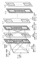
図7は、撮影画像における局所特徴を検出し、顔領域を特定するための一連の処理を示す図である。同図に示した処理では、まず最もプリミティブな局所特徴である一次特徴を検出する。一次特徴としては同図に示すように、縦特徴701,横特徴702,右上がり斜め特徴703,右下がり斜め特徴704といった特徴がある。ここで「特徴」とは、縦特徴701を例に取ると、縦方向のエッジセグメントを表すものである。
FIG. 7 is a diagram illustrating a series of processes for detecting a local feature in a captured image and specifying a face region. In the process shown in the figure, first, the primary feature which is the most primitive local feature is detected. As shown in the figure, the primary features include a
撮影画像において各方向のセグメントを検出する技術については周知であるので、この技術を用いて撮影画像から各方向のセグメントを検出し、撮影画像から縦特徴のみを検出した画像、撮影画像から横特徴のみを検出した画像、撮影画像から右上がり斜め特徴のみを検出した画像、撮影画像から右下がり斜め特徴のみを検出した画像を生成する。このことから4つの画像(一次特徴画像)のサイズ(縦横の画素数)は撮影画像と同じであるので、特徴画像と撮影画像とでは夫々画素が1対1に対応する。また、特徴画像において、検出した特徴部分の画素の値とそれ以外の部分の画素の値とは異なる値とし、例えば特徴部分の画素の値は1、それ以外の部分の画素の値は0とする。従って、特徴画像において画素値が1である画素があれば、撮影画像においてこれに対応する画素は一次特徴を構成する画素であるとすることができる。 Since a technique for detecting a segment in each direction in a captured image is well known, this technique is used to detect a segment in each direction from a captured image and detect only a vertical feature from the captured image, and a lateral feature from the captured image. An image in which only a diagonal feature that has been detected from the photographed image is detected, and an image in which only the oblique feature from the photograph that has been descended from the right is detected. From this, the size (number of vertical and horizontal pixels) of the four images (primary feature images) is the same as that of the photographed image, so that the pixels correspond to the feature image and the photographed image on a one-to-one basis. In the feature image, the pixel value of the detected feature portion is different from the pixel value of the other portion. For example, the pixel value of the feature portion is 1, and the pixel values of the other portions are 0. To do. Therefore, if there is a pixel having a pixel value of 1 in the feature image, the corresponding pixel in the captured image can be regarded as a pixel constituting the primary feature.
以上のようにして一次特徴画像群を生成することで、撮影画像における一次特徴を検出することができる。 By generating the primary feature image group as described above, the primary feature in the captured image can be detected.
次に、検出した一次特徴群の何れかを組み合わせた二次特徴群を撮影画像から検出する。二次特徴群としては同図に示すように、右空きV字特徴710,左空きV字特徴711,水平平行線特徴712,垂直平行線特徴713といった特徴がある。右空きV字特徴710は一次特徴である右上がり斜め特徴703と右下がり斜め特徴704とを組み合わせた特徴、左空きV字特徴711は一次特徴である右下がり斜め特徴704と右上がり斜め特徴703とを組み合わせた特徴であり、水平平行線特徴712は一次特徴である横特徴702を組み合わせた特徴であり、垂直平行線特徴713は一次特徴である縦特徴701を組み合わせた特徴である。
Next, a secondary feature group obtained by combining any of the detected primary feature groups is detected from the captured image. As shown in the figure, the secondary feature group has a right empty V-
一次特徴画像の生成と同様に、撮影画像から右空きV字特徴710のみを検出した画像、撮影画像から左空きV字特徴711のみを検出した画像、撮影画像から水平平行線特徴712のみを検出した画像、撮影画像から垂直平行線特徴713のみを検出した画像を生成する。このことから4つの画像(二次特徴画像)のサイズ(縦横の画素数)は撮影画像と同じであるので、特徴画像と撮影画像とでは夫々画素が1対1に対応する。また、特徴画像において、検出した特徴部分の画素の値とそれ以外の部分の画素の値とは異なる値とし、例えば特徴部分の画素の値は1、それ以外の部分の画素の値は0とする。従って、特徴画像において画素値が1である画素があれば、撮影画像においてこれに対応する画素は二次特徴を構成する画素であるとすることができる。
Similar to the generation of the primary feature image, an image in which only the right empty V-shaped
以上のようにして二次特徴画像群を生成することで、撮影画像における二次特徴を検出することができる。 By generating the secondary feature image group as described above, the secondary feature in the captured image can be detected.
次に、検出した二次特徴群の何れかを組み合わせた三次特徴群を撮影画像から検出する。三次特徴群としては同図に示すように、眼特徴720,口特徴721といった特徴がある。眼特徴720は二次特徴である右空きV字特徴710と左空きV字特徴711と水平平行線特徴712と垂直平行線特徴713とを組み合わせた特徴であり、口特徴721は二次特徴である右空きV字特徴710と左空きV字特徴711と水平平行線特徴712とを組み合わせた特徴である。
Next, a tertiary feature group combining any of the detected secondary feature groups is detected from the captured image. The tertiary feature group has features such as an
一次特徴画像の生成と同様に、眼特徴720のみを検出した画像、撮影画像から口特徴721のみを検出した画像を生成する。このことから2つの画像(三次特徴画像)のサイズ(縦横の画素数)は撮影画像と同じであるので、特徴画像と撮影画像とでは夫々画素が1対1に対応する。また、特徴画像において、検出した特徴部分の画素の値とそれ以外の部分の画素の値とは異なる値とし、例えば特徴部分の画素の値は1、それ以外の部分の画素の値は0とする。従って、特徴画像において画素値が1である画素があれば、撮影画像においてこれに対応する画素は三次特徴を構成する画素であるとすることができる。
Similar to the generation of the primary feature image, an image in which only the
以上のようにして三次特徴画像群を生成することで、撮影画像における三次特徴を検出することができる。 By generating the tertiary feature image group as described above, the tertiary feature in the captured image can be detected.
次に、検出した三次特徴群を組み合わせた四次特徴を撮影画像から検出する。四次特徴は同図では顔特徴そのものである。顔特徴は三次特徴である眼特徴72と口特徴721とを組み合わせた特徴である。
Next, a quaternary feature obtained by combining the detected tertiary feature groups is detected from the captured image. The quaternary feature is the facial feature itself in the figure. The facial feature is a feature that combines an eye feature 72 and a
一次特徴画像の生成と同様に、顔特徴を検出した画像(四次特徴画像)を生成する。このことから四次特徴画像のサイズ(縦横の画素数)は撮影画像と同じであるので、特徴画像と撮影画像とでは夫々画素が1対1に対応する。また、特徴画像において、検出した特徴部分の画素の値とそれ以外の部分の画素の値とは異なる値とし、例えば特徴部分の画素の値は1、それ以外の部分の画素の値は0とする。従って、特徴画像において画素値が1である画素があれば、撮影画像においてこれに対応する画素は四次特徴を構成する画素であるとすることができる。 従ってこの四次特徴画像を参照することで、例えば画素値が1である画素の重心位置をもって、顔領域の位置を求めることができる。 Similar to the generation of the primary feature image, an image (quaternary feature image) in which the facial feature is detected is generated. From this, the size (number of vertical and horizontal pixels) of the quaternary feature image is the same as that of the captured image, and therefore, the feature image and the captured image have a one-to-one correspondence with the pixels. In the feature image, the pixel value of the detected feature portion is different from the pixel value of the other portion. For example, the pixel value of the feature portion is 1, and the pixel values of the other portions are 0. To do. Therefore, if there is a pixel having a pixel value of 1 in the feature image, the corresponding pixel in the captured image can be regarded as a pixel constituting a quaternary feature. Therefore, by referring to this quaternary feature image, for example, the position of the face region can be obtained from the barycentric position of the pixel whose pixel value is 1.
なお、この顔領域を矩形とする場合、この矩形が撮影画像に対してどれだけどの方向に傾いているのかを示す情報を求めるために、この矩形の撮影画像に対する傾きを求めることで、上記回転量を求めることができる。 When this face area is a rectangle, in order to obtain information indicating how much the rectangle is tilted with respect to the captured image, the rotation is performed by calculating the inclination of the rectangle with respect to the captured image. The amount can be determined.
以上のようにして、上記顔領域情報を求めることができる。求めた顔領域情報は上述の通り、表情判別部104に出力する。
As described above, the face area information can be obtained. The obtained face area information is output to the facial
また、上記各特徴画像(本実施形態では一次特徴画像、二次特徴画像、三次特徴画像、四次特徴画像)は上記中間検出結果として中間検出結果保持部103に出力する。
Each feature image (primary feature image, secondary feature image, tertiary feature image, and quaternary feature image in this embodiment) is output to the intermediate detection
このようにして、撮影画像における四次特徴を検出することで、撮影画像における顔の領域を求めることができる。また、以上説明した顔領域の検出処理を撮影画像全体に対して行うことで、撮影画像に顔の領域が複数含まれていても、夫々の顔の領域を検出することができる。 Thus, by detecting the quaternary feature in the photographed image, the face area in the photographed image can be obtained. In addition, by performing the face area detection process described above on the entire captured image, each face area can be detected even if the captured image includes a plurality of face areas.
なお、上記顔領域の検出処理については、並列階層処理により画像認識を行う神経回路網を用いて実現することも可能であり、これについては、M.Matsugu,K.Mori,et.al, “Convolutional Spiking Neural Network Model for Robust Face Detection”,2002,Internatinal Conference On Neural Information Processing (ICONIP02)に記述がされている。 Note that the face area detection processing can also be realized using a neural network that performs image recognition by parallel hierarchical processing, which is described in M. Matsugu, K. Mori, et.al, “ Convolutional Spiking Neural Network Model for Robust Face Detection ”, 2002, Internatinal Conference On Neural Information Processing (ICONIP02).
図8を参照して神経回路網の処理内容を説明する。図8は、画像認識を行うための神経回路網の構成を示す図である。 The processing contents of the neural network will be described with reference to FIG. FIG. 8 is a diagram illustrating a configuration of a neural network for performing image recognition.
この神経回路網は、入力データ中の局所領域において、対象または幾何学的特徴などの認識(検出)に関与する情報を階層的に扱うものであり、その基本構造はいわゆるConvolutionalネットワーク構造(LeCun, Y. and Bengio, Y., 1995, “Convolutional Networks for Images Speech, and Time Series” in Handbook of Brain Theory and Neural Networks (M. Arbib, Ed.), MIT Press, pp.255-258)である。最終層(最上位層)では検出したい被写体の有無と、存在すればその入力データ上の位置情報が得られる。この神経回路網を本実施形態に適用すれば、この最終層からは、撮影画像中の顔の領域の有無と、顔の領域が存在すれば、この顔の領域の撮影画像上における位置情報が得られる。 This neural network hierarchically handles information related to recognition (detection) of objects or geometric features in a local region in input data, and its basic structure is a so-called Convolutional network structure (LeCun, Y. and Bengio, Y., 1995, “Convolutional Networks for Images Speech, and Time Series” in Handbook of Brain Theory and Neural Networks (M. Arbib, Ed.), MIT Press, pp. 255-258). In the final layer (uppermost layer), the presence / absence of the subject to be detected and the position information on the input data if it exists are obtained. If this neural network is applied to the present embodiment, from this final layer, the presence / absence of a face area in the photographed image and, if there is a face area, position information on the photographed image of this face area. can get.
同図においてデータ入力層801は、画像データを入力する層である。最初の特徴検出層(1,0)は、データ入力層801より入力された画像パターンの局所的な低次の特徴(特定方向成分、特定空間周波数成分などの幾何学的特徴のほか色成分特徴を含んでもよい)を全画面の各位置を中心として局所領域(或いは、全画面にわたる所定のサンプリング点の各点を中心とする局所領域)において同一箇所で複数のスケールレベル又は解像度で複数の特徴カテゴリの数だけ検出する。 In the figure, a data input layer 801 is a layer for inputting image data. The first feature detection layer (1, 0) is a local low-order feature of the image pattern input from the data input layer 801 (geometric features such as a specific direction component and a specific spatial frequency component, as well as a color component feature). Multiple features at multiple scale levels or resolutions at the same location in a local region (or a local region centered around each point of a predetermined sampling point across the entire screen) Detect only the number of categories.
特徴統合層(2,0)は、所定の受容野構造(以下、受容野とは直前の層の出力素子との結合範囲を、受容野構造とはその結合荷重の分布を意味する)を有し、特徴検出層(1,0)からの同一受容野内にある複数のニューロン素子出力の統合(局所平均化、最大出力検出等によるサブサンプリングなどの演算)を行う。この統合処理は、特徴検出層(1,0)からの出力を空間的にぼかすことで、位置ずれや変形などを許容する役割を有する。また、特徴統合層内のニューロンの各受容野は同一層内のニューロン間で共通の構造を有している。 The feature integration layer (2,0) has a predetermined receptive field structure (hereinafter, the receptive field means the coupling range with the output element of the immediately preceding layer, and the receptive field structure means the distribution of the coupled load). Then, the outputs of a plurality of neuron elements in the same receptive field from the feature detection layer (1, 0) are integrated (calculation such as sub-sampling by local averaging, maximum output detection, etc.). This integration process has a role of allowing positional deviation and deformation by spatially blurring the output from the feature detection layer (1, 0). Each receptive field of neurons in the feature integration layer has a common structure among neurons in the same layer.
後続の層である各特徴検出層(1,1)、(1,2)、…、(1,M)、及び各特徴統合層(2,1)、(2,2)、…、(2,M)は、上述した各層と同様に、前者((1,1)、…)は、各特徴検出モジュールにおいて複数の異なる特徴の検出を行い、後者((2,1)、…)は、前段の特徴検出層からの複数特徴に関する検出結果の統合を行う。但し、前者の特徴検出層は同一チャネルに属する前段の特徴統合層の細胞素子出力を受けるように結合(配線)されている。特徴統合層で行う処理であるサブサンプリングは、同一特徴カテゴリの特徴検出細胞集団からの局所的な領域(当該特徴統合層ニューロンの局所受容野)からの出力についての平均化などを行うものである。 Each feature detection layer (1,1), (1,2),..., (1, M) and each feature integration layer (2,1), (2,2),. , M), like the above-described layers, the former ((1, 1),...) Detects a plurality of different features in each feature detection module, and the latter ((2, 1),. Integration of detection results regarding multiple features from the previous feature detection layer is performed. However, the former feature detection layer is coupled (wired) to receive the cell element output of the former feature integration layer belonging to the same channel. Sub-sampling, which is a process performed in the feature integration layer, is to average the output from a local region (local receptive field of the feature integration layer neuron) from the feature detection cell population of the same feature category. .
図8に示した神経回路網を用いて、図7に示した各特徴を検出するためには、各特徴検出層の検出に使用する受容野構造をその特徴を検出するためのものにすることで、各特徴の検出が可能である。また、最終層の顔検出層における顔の検出に使用する受容野構造を、各サイズや各回転量に適したものを用意し、顔特徴の検出において、顔が存在するという結果を得たときにどの受容野構造を用いて検出したかによって、その顔の大きさや向き等の顔データを得ることが出来る。 In order to detect each feature shown in FIG. 7 using the neural network shown in FIG. 8, the receptive field structure used for detection of each feature detection layer is to detect the feature. Thus, each feature can be detected. In addition, when the receptive field structure used for face detection in the face detection layer of the final layer is prepared for each size and each rotation amount, and the result of face feature detection is obtained Depending on which receptive field structure is used for detection, face data such as the size and orientation of the face can be obtained.
図2に戻って、次に、制御部101は、ステップS202で顔検出部102による顔領域検出処理の結果を参照して、撮影画像において顔領域が存在したか否かを判定する(ステップS203)。この判定方法としては、例えば四次特徴画像が得られたか否かを判定し、得られた場合には顔領域が撮影画像中に存在すると判定する。またその他にも、(顔)特徴検出層内の各ニューロンのうち、出力値がある基準値以上のニューロンが存在するかを判定し、基準値以上のニューロンが示す位置に顔(領域)が存在するとしても良い。その場合、基準値以上のニューロンが存在しない場合は、顔が存在しないとする。
Returning to FIG. 2, next, the
そしてステップS203における判定処理の結果、撮影画像中に顔領域が存在しない場合、顔検出部102はその旨を制御部101に通知するので、処理をステップS201に戻し、制御部101は撮像部100を制御して、新たな画像を撮影する。
If the face area does not exist in the captured image as a result of the determination process in step S203, the
一方、顔領域が存在した場合、顔検出部102はその旨を制御部101に通知するので、処理をステップS204に進め、制御部101は画像保持部105に保持されている撮影画像を表情判別部104に出力すると共に、中間検出結果保持部103に保持されている特徴画像を表情判別部104に出力し、表情判別部104は、入力された特徴画像と顔領域情報を用いて、撮影画像中の顔領域に含まれる顔の表情を判定する処理を行う(ステップS204)。
On the other hand, if a face area exists, the
なお、画像保持部105から表情判別部104に出力する画像は本実施形態では撮影画像全体とするが、これに限定されるものではなく、例えば制御部101が顔領域情報を用いて撮影画像中の顔領域を特定し、この顔領域のみの画像を表情判別部104に出力するようにしても良い。
Note that the image output from the
次に、表情判別部104が行う表情判定処理について、より詳細に説明する。上述のように、顔の表情を判別するために、一般的な表情記述法であるFACS(Facial Action Coding System)で用いられるAction Unit(AU)を検出し、検出したAUの種類により、表情判別を行うことが出来る。AUには、眉の外側を上げる、唇を横に引っ張る等がある。AUの組み合わせにより人間のあらゆる表情の記述は可能であるため、原理的には、AUが全て検出できれば、全ての表情を判別することが可能である。しかし、AUは44個あり、全てを検出するのは容易ではない。
Next, the facial expression determination process performed by the facial
そこで本実施形態では図9に示すように、眉の端点(B1〜B4)、目の端点(E1〜E4)、口の端点(M1,M2)を表情判別に使用する特徴とし、それら特徴点の相対位置の変化を求めることにより表情を判別する。これらの特徴点の変化でいくつかのAUは記述可能であり、基本的な表情の判別は可能である。なお、各表情における各特徴点の変化は、表情判別データとして表情判別部104の中に保持されており、表情判別部104の表情判別処理に使用される。
Therefore, in this embodiment, as shown in FIG. 9, the eyebrow end points (B1 to B4), the eye end points (E1 to E4), and the mouth end points (M1 and M2) are used for facial expression discrimination, and these feature points. The facial expression is discriminated by determining the change in the relative position of the. Some AUs can be described by changes in these feature points, and basic facial expressions can be distinguished. The change of each feature point in each facial expression is held in the facial
図9は、各特徴点を示す図である。 FIG. 9 is a diagram showing each feature point.
図9に示した表情検出のための各特徴点は、目や眉などの端部であり、この端部の形状は大まかには右空きのV字、左空きのV字であるので、例えば図7に示した二次特徴の右空きV字特徴710,左空きV字特徴711に相当する。
Each feature point for facial expression detection shown in FIG. 9 is an end portion of eyes, eyebrows, and the like, and the shape of this end portion is roughly a right empty V character and a left empty V character. This corresponds to the right empty V-
また、表情判別に使用する特徴点の検出は、顔検出部102における顔検出処理の中間段階で得られている。そして、その顔検出処理の中間処理結果は、中間特徴結果保持部103に保持されている。
In addition, detection of feature points used for facial expression discrimination is obtained at an intermediate stage of face detection processing in the
しかしながら、右空きV字特徴710,左空きV字特徴711は、顔以外にも、背景等、様々な位置に存在する。そのため、顔検出部102で得られた顔領域情報を用いて二次特徴画像中の顔領域を特定し、この領域において右空きV字特徴710,左空きV字特徴711の端点、即ち眉の端点、目の端点、口の端点を検出する。
However, the right empty V-shaped
そこで、図9に示すように、顔領域内で眉・目の端点の探索範囲(RE1,RE2)と口の端点の探索範囲(RM)を設定する。そして、その設定した探索範囲内の画素値を参照して、右空きV字特徴710,左空きV字特徴711を構成する画素群のうち、同図水平方向に両端の画素の位置を検出し、検出した位置をもって特徴点の位置とする。なお顔領域の中心位置に対するこの探索範囲(RE1,RE2,RM)の相対位置は予め設定されている。
Therefore, as shown in FIG. 9, the search range (RE1, RE2) of the eyebrow / eye end points and the search range (RM) of the mouth end points are set in the face region. Then, referring to the pixel values within the set search range, the positions of the pixels at both ends in the horizontal direction in the figure are detected from among the pixel groups constituting the right empty V-shaped
例えば探索範囲RE1内で右空きV字特徴710を構成する画素群のうち、同図水平方向に端の画素の位置はB1,E1であるので、これを眉、目何れかの一端の位置とする。また、夫々の位置B1,E1の垂直方向の位置を参照し、より上側に位置するものが眉の一端の位置とする。同図ではB1がE1に比べてより上の位置にあるので、B1を眉の一端の位置とする。
For example, in the pixel group constituting the right empty V-shaped
このようにして、目、眉の一端の位置を求めることができる。同様に探索範囲RE1において左空きV字特徴711について同様の処理を行うことで、眉、目のもう一端の位置B2,E2の位置を求めることができる。
In this way, the position of one end of the eyes and eyebrows can be obtained. Similarly, by performing the same processing for the left empty V-shaped
以上説明した処理により、目、眉、そして口の両端の位置、即ち各特徴点の位置を求めることができる。なお、特徴画像と撮影画像とはサイズが同じで、且つ各画素が1対1で対応するので、特徴画像中の各特徴点の位置はそのまま撮影画像中における位置とすることもできる。 By the processing described above, the positions of the eyes, the eyebrows, and both ends of the mouth, that is, the positions of the feature points can be obtained. Since the feature image and the captured image have the same size and correspond to each pixel on a one-to-one basis, the position of each feature point in the feature image can be used as it is in the captured image.
なお、本実施形態では各特徴点の位置を求める処理に二次特徴を用いたが、これに限定されるものではなく、一次特徴や三次特徴等の何れか若しくはその組み合わせを用いても良い。 In the present embodiment, the secondary feature is used for the process of obtaining the position of each feature point. However, the present invention is not limited to this, and any one or a combination of the primary feature, the tertiary feature, or the like may be used.
例えば右空きV字特徴710,左空きV字特徴711以外に、図7に示した三次特徴である目特徴720と口特徴721、及び一次特徴である縦特徴701,横特徴702,右上がり斜め特徴703,右下がり斜め特徴704を用いることもできる。
For example, in addition to the right empty V-
一次特徴と三次特徴とを用いて特徴点を求める処理を図10を用いて説明する。図10は図9に示した顔領域において一次特徴と三次特徴とを用いた特徴点を求める処理を説明するための図である。 Processing for obtaining feature points using primary features and tertiary features will be described with reference to FIG. FIG. 10 is a diagram for explaining processing for obtaining feature points using primary features and tertiary features in the face area shown in FIG. 9.
図10に示すように、目探索範囲(RE3、RE4)と口探索範囲(RM2)を設定し、そして、その設定した探索範囲内の画素値を参照して、目特徴720、口特徴721を構成する画素群が配置されている範囲を求める。そしてこの範囲を網羅するように、眉・目の端点の探索範囲(RE5,RE6)と口の端点の探索範囲(RM3)を設定する。
As shown in FIG. 10, an eye search range (RE3, RE4) and a mouth search range (RM2) are set, and the
そして次に、夫々の探索範囲(RE5,RE6,RM3)内で縦特徴701,横特徴702,右上がり斜め特徴703,右下がり斜め特徴704から成る連続した線分上を追跡し、その結果、水平方向に両端の位置を求め、目、眉、口の両端を求めることができる。1次特徴は基本的にエッジ抽出であるので、各検出結果に対して、あるしきい値以上の領域を細線化し、その結果を追跡することで端点を検出することが出来る。
Then, in each search range (RE5, RE6, RM3), a continuous line segment consisting of a
次に、求めた各特徴点を用いて行う、表情の判定処理について説明する。表情の判別の個人差を無くすために、まず無表情の時の顔画像に対して、顔検出処理を行い、各局所特徴の検出結果を求める。そして、それらの検出結果を用いて、図9または図10に示した各特徴点の相対位置を求め、基準となる相対位置としてそのデータを表情判別部104に保持させておく。そして表情判別部104は、その基準の相対位置と、上記求めた各特徴点の相対位置とを参照し、夫々の特徴点が基準からどれだけ変化したか、即ち「ずれ」を求める処理を行う。なお、撮影した画像中の顔のサイズと予め撮影した無表情の時の顔のサイズは一般的に異なるため、求めた各特徴点のうちの相対位置、例えば両目間の距離に基づいて、各特徴点の位置を正規化する。
Next, facial expression determination processing performed using each obtained feature point will be described. In order to eliminate individual differences in facial expression discrimination, face detection processing is first performed on the face image when there is no expression, and the detection result of each local feature is obtained. Then, using these detection results, the relative position of each feature point shown in FIG. 9 or FIG. 10 is obtained, and the data is held in the facial
そして、各特徴点毎にその変化に依存した得点を求め、その得点の分布に基づいて、表情を判別する。例えば、喜びの表情を示す表情は、(1)眼尻が下がる、(2)頬の筋肉が持ち上がる、(3)口の端が持ち上がるなどの特徴が見られるため、「眼の端点から口端点までの距離」、「口の横幅の長さ」、「眼の横幅の長さ」に大きな変化が現れる。そして、それらの変化から求めた得点分布は、喜び表情に特有な得点分布となる。 Then, a score depending on the change is obtained for each feature point, and the facial expression is discriminated based on the distribution of the score. For example, the expression of joy is characterized by (1) lowering of the buttocks, (2) lifting of the cheek muscles, and (3) lifting of the edge of the mouth. Change in “distance to”, “width of mouth width”, and “length of eye width”. And the score distribution obtained from these changes is a score distribution peculiar to a joyful expression.
この特有な得点分布は他の表情に関しても同様なことが言える。従って、分布の形状を混合ガウシアン近似してパラメトリックにモデル化し、求めた得点分布と各表情毎に設けられた得点分布との類似度判別を、パラメータ空間内の距離の大小を判定することにより求める。そして、求めた得点分布とより類似度の高い得点分布(より距離の小さい得点分布)が示す表情を、判定結果としての表情とする。 This unique score distribution is the same for other facial expressions. Therefore, the distribution shape is modeled parametrically by mixed Gaussian approximation, and similarity determination between the obtained score distribution and the score distribution provided for each facial expression is obtained by determining the magnitude of the distance in the parameter space. . Then, the facial expression indicated by the score distribution having a higher degree of similarity to the obtained score distribution (score distribution with a smaller distance) is used as the facial expression as the determination result.
また、得点総和に対して、閾値処理を行なう方法も適用可能である。この閾値処理は、表情場面に類似した非表情場面(例えば、会話中で”い”という発音をした顔)と表情場面とを正確に判別するためにより有効である。なお、得点分布形状の判別と総和の閾値処理のいずれか一方を行っても良い。このように得点分布と得点の総和の閾値処理から表情の判定を行うことにより、正確に表情場面を認識し検出率を向上することができる。 A method of performing threshold processing on the score total is also applicable. This threshold processing is more effective for accurately discriminating a non-expression scene similar to an expression scene (for example, a face pronounced “i” in conversation) and an expression scene. Note that either the discrimination of the score distribution shape or the threshold processing of the sum may be performed. Thus, by performing facial expression determination from the threshold distribution of the score distribution and the sum of the scores, the facial expression scene can be accurately recognized and the detection rate can be improved.
以上の処理によって、顔の表情を判定することができたので、表情判別部104は、判定した表情に応じたコード(各表情に個別のコード)を出力する。このコードは例えば番号であっても良いし、その表現方法は特に限定されるものではない。
Since the facial expression can be determined by the above processing, the facial
次に表情判別部104は、判定した表情が、予め設定された特定の表情(例えば笑顔)であるか否かを判定し、その判定結果を制御部101に通知する(ステップS205)。
Next, the facial
ここで、ステップS204までの処理により判定した表情が、予め設定された特定の表情と同じであった場合、例えば本実施形態の場合には、表情判別部104が出力した「表情を示すコード」と、予め設定された特定の表情を示すコードとが一致した場合、制御部101は画像保持部105が保持している撮影画像を記録部107に記録する。また、記録部107がDVD−RAMやコンパクトフラッシュ(登録商標)である場合には、制御部101は記録部107を制御してDVD−RAMやコンパクトフラッシュ(登録商標)等の記憶媒体に撮影画像を記録する(ステップS206)。また、記録する画像を、顔領域の画像、即ち、特定の表情の顔画像としても良い。
Here, if the facial expression determined by the processing up to step S204 is the same as the specific facial expression set in advance, for example, in the case of the present embodiment, the “code indicating the facial expression” output by the facial
一方、ステップS204までの処理により判定した表情が、予め設定された特定の表情と同じではなかった場合、例えば本実施形態の場合には、表情判別部104が出力した「表情を示すコード」と、予め設定された特定の表情を示すコードとが一致しなかった場合、制御部101は撮像部100を制御し、新たな画像を撮影させる。
On the other hand, when the facial expression determined by the processing up to step S204 is not the same as the specific facial expression set in advance, for example, in the case of the present embodiment, the “expression indicating facial expression” output by the facial
なお、判定された表情が特定の表情であった場合にはその他にも、例えばステップS206で、制御部101が撮像部100を制御して次の画像を撮影させつつ、撮影した画像を記録部107に保持させるようにしても良い。また、制御部101は表示部106を制御して、撮影した画像を表示部106に表示しても良い。
In addition, when the determined facial expression is a specific facial expression, for example, in step S206, the
一般に表情は急激に変化するものではなく、或程度の連続性を有するものであるので、上記ステップS202、ステップS204における処理が比較的短時間で終了すると、特定の表情を示した画像と連続した画像も同様な表情を示していることが多い。そこで、ステップS202で検出された顔領域をより明瞭とすべく、制御部101が撮影部100の撮影パラメータ(露出補正、自動焦点、色補正等、撮像系の撮像パラメータ)を設定し、再撮影を行ない、表示、記録するように動作させることも可能である。
In general, the facial expression does not change abruptly but has a certain degree of continuity. Therefore, when the processing in step S202 and step S204 is completed in a relatively short time, it continues with an image showing a specific facial expression. The images often show similar expressions. Therefore, in order to make the face area detected in step S202 clearer, the
図11は本実施形態に係る画像処理装置の基本構成を示す図である。 FIG. 11 is a diagram showing a basic configuration of the image processing apparatus according to the present embodiment.
1001はCPUで、RAM1002やROM1003に格納されたプログラムやデータを用いて本装置全体の制御を行うと共に、上記表情判定に係る一連の処理を実行する。またCPU1001は図1では上記制御部101に相当するものである。
A
1002はRAMで、外部記憶装置1007や記憶媒体ドライブ1008からロードされたプログラムやデータ、I/F1009を介して撮像部100から入力される画像のデータなどを一時的に格納するエリアを備えると共に、CPU1001が各種の処理を実行する為に必要なエリアも備える。図1では中間検出結果保持部103と画像保持部105とがこのRAM1002に相当する。
A
1003はROMで、例えば本装置全体のボートプログラムや設定データなどを格納する。
1004、1005は夫々キーボード、マウスで、夫々CPU1001に対して各種の指示を入力するために用いる。
1006は表示装置で、CRTや液晶画面などにより構成されており、画像や文字などにより構成されている各種の情報を表示することができる。図1では表示部106に相当するものである。
A
1007は外部記憶装置で、ハードディスクドライブ装置などの大容量情報記憶装置として機能するものであり、ここにOS(オペレーティングシステム)やCPU1001が上記表情判定に係る一連の処理を実行する為に実行するプログラムなどを保存している。そしてこのプログラムはCPU1001からの指示により、RAM1002に読み出され、CPU1001により実行されるものである。なお、このプログラムは、図1に示した顔検出部102、表情判別部104をプログラムにより実現した場合には、この顔検出部102、表情判別部104に相当するプログラムを含むものである。
1008は記憶媒体ドライブ装置1008で、CD−ROMやDVD−ROM等の記憶媒体に記録されたプログラムやデータを読み出してRAM1002や外部記憶装置1007に出力するものである。なお、CPU1001が上記表情判定に係る一連の処理を実行する為に実行するプログラムをこの記憶媒体に記録しておき、CPU1001からの指示により、記憶媒体ドライブ装置1008がRAM1002に読み出すようにしても良い。
1009はI/Fで、図1に示した撮像部100と本装置を接続するためのもので、撮像部100が撮像した画像のデータはI/F1009を介してRAM1002に出力される。
1010は上記各部を繋ぐバスである。
続いて、本実施形態に係る画像処理装置を撮像装置に搭載させることにより、被写体が特定表情の場合に撮影を行う場合について、図12を参照して説明する。図12は本実施形態に係る画像処理装置を撮像装置に用いた例の構成を示す図である。 Next, a case where shooting is performed when the subject has a specific facial expression by mounting the image processing apparatus according to the present embodiment on the imaging apparatus will be described with reference to FIG. FIG. 12 is a diagram illustrating a configuration of an example in which the image processing apparatus according to the present embodiment is used in an imaging apparatus.
図12中の撮像装置5101は、撮影レンズおよびズーム撮影用駆動制御機構を含む結像光学系5102、CCD又はCMOSイメージセンサー5103、撮像パラメータの計測部5104、映像信号処理回路5105、記憶部5106、撮像動作の制御、撮像条件の制御などの制御用信号を発生する制御信号発生部5107、EVFなどファインダーを兼ねた表示ディスプレイ5108、ストロボ発光部5109、記録媒体5110などを具備し、更に上述した画像処理装置5111を表情検出装置として備える。
An
この撮像装置5101は、例えば撮影された映像中から人物の顔画像の検出(存在位置・サイズ・回転角度の検出)と表情の検出を画像処理装置5111により行う。そして、その人物の位置情報や表情情報等が画像処理装置5111から制御信号発生部5107に入力されると、同制御信号発生部5107は、撮像パラメータ計測部5104からの出力に基づき、その人物の画像を最適に撮影する制御信号を発生する。具体的には、例えば、人物の顔画像が撮影領域の中央に、所定以上のサイズで正面向きに得られ、笑った表情のときを撮影時点とすることができる。
The
上述した画像処理装置を、このように撮像装置に用いることで、顔検出と表情検出、それに基づくタイミングの良い撮影を行うことができるようになる。なお、上記説明では、上述した処理装置を画像処理装置5111として備える撮像装置5101について説明したが、当然、上述したアルゴリズムをプログラムとして実装し、CPUで動作させる処理手段として、撮像装置5101に搭載することも可能である。
By using the above-described image processing apparatus in the imaging apparatus in this way, it is possible to perform face detection, facial expression detection, and shooting with good timing based on the detection. In the above description, the
またこの撮像装置に適用可能な画像処理装置としては本実施形態に係るものに限定されるものではなく、以下説明する実施形態に係る画像処理装置を適用しても良い。 Further, the image processing apparatus applicable to the imaging apparatus is not limited to the one according to the present embodiment, and the image processing apparatus according to the embodiment described below may be applied.
上記説明したように、本実施形態に係る画像処理装置は、一次特徴、二次特徴、、、というような局所特徴を用いるので、撮影画像における顔の領域を特定できるだけでなく、新たに口や目などの検出処理を行うことなく、より簡便に表情の判定処理を行うことができる。 As described above, the image processing apparatus according to the present embodiment uses local features such as a primary feature, a secondary feature, etc., so that not only can a facial region in a captured image be identified, It is possible to more easily perform facial expression determination processing without performing eye detection processing.
また、撮影画像中における顔の位置や向きなどがまちまちであっても、上記各局所特徴を求めることが出来、その結果、表情の判定処理を行うことができるので、撮影画像中における顔の位置や向きなどにロバストな表情判定を行うことができる。 In addition, even if the position and orientation of the face in the captured image vary, the above local features can be obtained, and as a result, facial expression determination processing can be performed, so the position of the face in the captured image Robust facial expressions can be determined for the direction and direction.
また本実施形態によれば、何度も撮影を行う過程において、特定の表情のみを撮影することができる。 Further, according to the present embodiment, only a specific facial expression can be photographed in the process of photographing many times.
なお、本実施形態では顔の領域を検出するための画像は撮影画像であったが、これに限定されるものではなく、予め保存しておいたものであっても良いし、ダウンロードしたものであっても良い。 In this embodiment, the image for detecting the face area is a captured image. However, the image is not limited to this. The image may be saved in advance or downloaded. There may be.
[第2の実施形態]
本実施形態では、第1の実施形態における顔検出領域の検出処理(ステップS202)と表情判別処理(ステップS204)とを並列に行なう。これにより、全体の処理をより高速に行うことができる。
[Second Embodiment]
In the present embodiment, the face detection area detection process (step S202) and the facial expression determination process (step S204) in the first embodiment are performed in parallel. Thereby, the whole process can be performed at higher speed.
図3は、本実施形態に係る画像処理装置の機能構成を示す図である。本実施形態に係る構成において、実質的には中間検出結果保持部303の構成と、画像保持部305の構成が第1の実施形態に係るそれとは異なっている。
FIG. 3 is a diagram illustrating a functional configuration of the image processing apparatus according to the present embodiment. In the configuration according to the present embodiment, the configuration of the intermediate detection
中間検出結果保持部303はさらに、中間検出結果保持部A313と中間検出結果保持部B314で構成されている。また、画像保持部305も同様に、画像保持部A315と画像保持部B316で構成されている。
The intermediate detection
続いて、図3に示す構成の動作を、図4のタイミングチャートを用いて説明する。 Next, the operation of the configuration shown in FIG. 3 will be described using the timing chart of FIG.
図4のタイミングチャートにおいて、“A”の表示はAモードで動作することを、“B”の表示はBモードで動作することを示している。「画像撮影」のAモードとは、撮影した画像を画像保持部305に保持する際に、画像保持部A315に保持することを、Bモードとは、画像保持部B316に保持することを示す。以下、画像撮影のAモードとBモードとは交互に切り替わり、それに応じて撮像部300は画像の撮影を行うことから、撮像部300は連続して画像を撮影を行う。なお撮影のタイミングは制御部101が与えるものとする。
In the timing chart of FIG. 4, “A” indicates that the operation is in the A mode, and “B” indicates that the operation is in the B mode. The A mode of “image shooting” indicates that the captured image is held in the image holding unit A315 when the image is held in the
また、「顔検出」のAモードとは、顔検出部302の顔領域検出処理において、中間処理結果を中間検出結果保持部303に保持する際に、中間検出結果保持部A313に保持することを、Bモードとは、中間検出結果保持部B314に保持することを示す。
Further, the “face detection” A mode refers to holding in the intermediate detection result holding unit A313 when holding the intermediate processing result in the intermediate detection
さらに「表情判別」のAモードとは、表情判別部304の表情判別処理において、画像保持部A315に保持された画像と中間検出結果保持部A313に保持された中間処理結果、及び顔検出部302の顔領域情報を用いて表情を判別することを示し、またBモードとは、画像保持部B316に保持された画像と中間検出結果保持部B314に保持された中間特徴検出結果、及び顔検出部302の顔領域情報とを用いて表情を判別することを示す。
Further, the A mode of “expression discrimination” refers to the image held in the image holding
次に、本実施形態に係る画像処理装置の動作について説明する。 Next, the operation of the image processing apparatus according to this embodiment will be described.
最初に画像撮影のAモードで画像の撮影を行なうことにより、画像保持部305の画像保持部A315に撮影された画像が保持される。また、表示部306に画像が表示され、さらに顔検出部302に画像が入力される。次に、顔検出部302では、入力された画像に対して、第1の実施形態と同様な処理を行うことにより顔領域情報を生成する処理を行う。そして、画像中に顔が検出されれば、顔領域情報のデータが表情判別部304に入力される。また、その顔検出処理の途中で得られる中間特徴検出結果を中間検出結果保持部303の中間検出結果保持部A313に保持させる。
First, the captured image is held in the image holding unit A315 of the
次に、Bモードの画像撮影とBモードの顔検出処理、Aモードの表情判別処理が並列に行なわれる。Bモードの画像撮影では、画像保持部305の画像保持部B316に撮影された画像が保持される。また、表示部306に画像が表示され、さらに顔検出部302に画像が入力される。そして、顔検出部302で、入力された画像に対して、第1の実施形態と同様の処理を行うことにより顔領域情報を生成する処理を行い、中間処理結果保持部B314に中間処理結果を保持する。
Next, B-mode image capturing, B-mode face detection processing, and A-mode facial expression determination processing are performed in parallel. In B-mode image capturing, the captured image is stored in the image storage unit B316 of the
また、上記のBモードの画像撮影とBモードの顔領域検出処理と並列に、Aモードの表情判別処理が行なわれる。Aモードの表情判別処理では、表情判別部304で、画像保持部A315から入力された画像に対して、顔検出部302からの顔領域情報及び中間検出結果保持部A313に保持された中間特徴検出結果を用い、表情判別部304で顔の表情を判別する。表情判別部304で判別した表情が所望の表情の場合は、画像保持部A315の画像を記録して終了となる。
In addition, the A-mode facial expression discrimination process is performed in parallel with the B-mode image capture and the B-mode face area detection process. In the A mode facial expression determination process, the facial
表情判別部304で判別した表情が所望の表情と異なる場合は、続いて、Aモードの画像撮影とAモードの顔領域検出処理、Bモードの表情判別処理が並列に行なわれる。Aモードの画像撮影では、画像保持部305の画像保持部A315に撮影された画像が保持される。また、表示部306に画像が表示され、さらに顔検出処理部302に画像が入力される。続いて、顔検出部302で、入力された画像に対して、顔領域を検出する処理を行う。また、並列に行なわれる、Bモードの表情判別処理では、表情判別部304で、画像保持部B316から入力された画像に対して、顔検出部302からの顔領域情報及び中間検出結果保持部B314に保持された中間検出結果を用い、表情判別部304で顔の表情を検出する。
If the facial expression discriminated by the facial
以下、表情判別部304で判別した表情が特定の表情と判定されるまで、同様の処理を繰り返す。そして、所望の表情と判別されると、表情判別処理がAモードであれば画像保持部A315の画像を、Bモードであれば画像保持部B316の画像を記録して終了となる。
Thereafter, the same processing is repeated until the facial expression determined by the facial
なお、各処理におけるモードの切り替えは制御部101が行い、そのタイミングは顔検出部102が行う顔検出処理の終了を制御部101が検知した時点でモードの切り替えを行うものとする。
Note that the mode switching in each process is performed by the
このように、画像保持部305が画像保持部A315及び画像保持部B316から、また中間検出結果保持部303が中間検出結果保持部A313及び中間検出結果保持部B314から構成されているため、画像撮影及び顔領域検出処理、と表情判別処理とを並列に行なうことが出来、結果として、表情を判別する画像の撮影レートを上げることが出来る。
As described above, the
[第3の実施形態]
本実施形態に係る画像処理装置は、第1,2の実施形態における顔検出部102が行う顔領域検出処理と、表情判別部104が行う表情判別処理とを並列に行なうことにより、システム全体のパフォーマンスを向上させることを目的とする。
[Third Embodiment]
The image processing apparatus according to this embodiment performs the face area detection processing performed by the
第2の実施形態では、画像撮影及び顔領域検出処理の方が、表情判別処理よりも動作時間がかかることを利用して、表情判別処理と、次の画像の撮影及び次の画像中の顔領域の検出処理を並列に行なっていた。それに対し本実施形態では、顔検出処理において、第1の実施形態の図7に示した4次特徴量を検出する処理が、1次特徴量から3次特徴量を検出するのと比較して処理時間がかかることを利用して、顔領域情報は前画像の検出結果を利用し、目や口といった表情の検出に使用する特徴点の検出結果は現画像の検出結果を利用する。これにより、顔領域検出処理と表情判別処理の並列処理を実現するものである。 In the second embodiment, using the fact that the image shooting and face area detection processing takes more time than the expression determination processing, the expression determination processing, the next image shooting, and the face in the next image are processed. Region detection processing was performed in parallel. On the other hand, in this embodiment, in the face detection process, the process of detecting the quaternary feature quantity shown in FIG. 7 of the first embodiment is compared with the detection of the tertiary feature quantity from the primary feature quantity. Taking advantage of the processing time, the detection result of the previous image is used for the face area information, and the detection result of the current image is used for the detection result of the feature points used for detection of facial expressions such as eyes and mouth. Thereby, parallel processing of face area detection processing and facial expression discrimination processing is realized.
図5は本実施形態に係る画像処理装置の機能構成を示す図である。 FIG. 5 is a diagram illustrating a functional configuration of the image processing apparatus according to the present embodiment.
撮像部500は時系列画像又は動画像を撮像して、各フレームの画像のデータを顔検出部502、画像保持部505、表示部506、記録部507に出力するものである。本実施形態に係る構成において、実質的には、顔検出部502と表情判別部504とが第1の実施形態に係るそれとは異なっている。
The
顔検出部502は、第1の実施形態に係る顔領域検出処理と同じ処理を行うのであるが、その処理が終了すると、終了信号を表情判別部504に出力する。
The
表情判別部504は、さらに前画像検出結果保持部514を含む構成を備える。
The facial
次に、図5に示した各部が行う処理について、図6に示すタイミングチャートを用いて説明する。 Next, processing performed by each unit illustrated in FIG. 5 will be described with reference to a timing chart illustrated in FIG.
撮像部500により最初のフレームの画像が撮影されると、この画像のデータは顔検出部502に入力される。顔検出部502では、入力された画像に対して、第1の実施形態と同様の処理を行うことにより顔領域情報を生成し、表情判別部504に出力する。表情判別部504に入力された顔領域情報は前画像検出結果保持部514に保持される。また、その途中で得られる中間特徴検出結果は中間検出結果保持部503に入力され、保持される。
When the image of the first frame is taken by the
続いて、次のフレームの画像が撮像部500により撮影されると、この画像のデータは画像保持部505に入力される。また、表示部506にその撮影された画像が表示され、さらに顔検出部502に画像が入力される。そして、顔検出部502は第1の実施形態と同様の処理を行うことにより顔領域情報を生成する。この顔領域検出処理が終了すると、顔検出部502は、その中間特徴の検出結果を中間検出結果保持部503に入力するとともに、表情判別部504が行うべき一連の処理が終了したことを示す信号を出力する。
Subsequently, when the image of the next frame is taken by the
そして、表情判別部504の判別結果の表情が、所望の表情でなかった場合は、顔検出部502で得られた顔領域情報を表情判別部504の前画像検出結果保持部514に保持する。
If the facial expression of the discrimination result of the facial
表情判別部504では、顔検出部502から上記終了信号を受けると、前画像検出結果保持部514に保持されている前画像(一つ若しくはそれ以上前のフレームの画像)に対する顔領域情報601と、画像保持部505に保持されている現画像(現在のフレームの画像)と、中間検出結果保持部503に保持されている現画像の中間特徴検出結果602を用いて、現画像に対する表情判別処理を行う。
When the facial
即ち、1つ若しくはそれ以上前のフレームの画像において顔領域情報によって特定される領域に位置的に対応する原画像中の領域について、この領域から得られた中間検出結果を用いて表情判別処理を行う。 That is, for an area in the original image that corresponds in position to the area specified by the face area information in the image of one or more previous frames, facial expression discrimination processing is performed using the intermediate detection result obtained from this area. Do.
前画像を撮影した時間と現画像を撮影した時間との差が短ければ、夫々の画像中の顔領域の位置は大きくは変化しない。そのため、上記のように、顔領域情報は前画像から得られたものを使用し、図9、図10に示した探索領域をより広く設定することで、前画像と現画像の顔領域の位置等のずれによる影響を抑えることができ、表情の判別処理を行なうことができる。 If the difference between the time when the previous image was taken and the time when the current image was taken is short, the position of the face area in each image does not change significantly. Therefore, as described above, the face area information obtained from the previous image is used, and the search areas shown in FIGS. 9 and 10 are set wider so that the positions of the face areas of the previous image and the current image are set. The influence of such a shift can be suppressed, and facial expression discrimination processing can be performed.
表情判別部504で判別した表情が所望の表情の場合は、画像保持部505の画像を記録して終了となる。表情判別部504で判別した表情が所望の表情と異なる場合は、次の画像を撮影し、顔検出部502で顔検出処理を行い、また表情判別部504で、撮影した画像、前画像検出結果保持部514に保持されている前画像に対する顔検出結果、中間検出結果保持部503に保持されている中間処理結果を用いて、表情の判別処理が行われる。
If the facial expression discriminated by the facial
以下、表情判別部504で判別した表情が所望の表情になるまで、同様の処理を繰り返す。そして、所望の表情と判別されると、画像保持部505の画像を記録して終了となる。
Thereafter, the same processing is repeated until the facial expression determined by the facial
このように、前画像検出結果保持部514に保持されている前画像に対する顔領域情報と中間検出結果保持部503に保持されている中間特徴検出処理結果を用いて、表情の判別処理が行われることにより、顔領域検出処理と表情判別処理とを並列に行なうことが出来、結果として、表情を判別する画像の撮影レートを上げることが出来る。
In this way, facial expression discrimination processing is performed using the face area information for the previous image held in the previous image detection
[第4の実施形態]
上記実施形態では顔の表情を判別する為の技術について説明したが、本実施形態では、その顔が誰のものであるかの判別、すなわち顔に対する個人の判別するための技術について説明する。
[Fourth Embodiment]
Although the technique for discriminating the facial expression has been described in the above embodiment, this embodiment will explain a technique for discriminating who the face belongs to, that is, a technique for discriminating an individual with respect to the face.
図13は本実施形態に係る画像処理装置の機能構成を示す図である。本実施形態に係る画像処理装置は、撮像部1300、制御部1301、顔検出部1302、中間検出結果保持部1303、個人判別部1304、画像保持部1305、表示部1306、記録部1307から成る。以下、各部について説明する。
FIG. 13 is a diagram illustrating a functional configuration of the image processing apparatus according to the present embodiment. The image processing apparatus according to this embodiment includes an
撮像部1300は、制御部1301からの制御信号に基づいて画像を撮影し、その撮影した画像(撮影画像)を、顔検出部1302、画像保持部1305、表示部1306若しくは記録部1307に出力する。
The
制御部1301は、本実施形態に係る画像処理装置全体を制御するための処理を行うものであり、撮像部1300、顔検出部1302、中間検出結果保持部1303、個人判別部1304、画像保持部1305、表示部1306、記録部1307と接続されており、各部が適切なタイミングで動作するよう、各部を制御するものである。
The
顔検出部1302は、撮像部1301からの撮影画像において顔の領域(撮影画像中に含まれる顔の画像の領域)を検出する処理を行う。この処理は即ち、撮影画像中の顔領域の有無の判別、顔領域が存在する場合にはこの顔領域の数、撮影画像における顔領域の座標位置、顔領域のサイズ、顔領域の撮影画像における回転量(例えば顔領域を矩形とする場合、この矩形が撮影画像においてどの方向にどれだけ傾いているかを示す回転量)を求める処理に換言される。なお、これらの情報(撮影画像中の顔領域の数、撮影画像における顔領域の座標位置、顔領域のサイズ、顔領域の撮影画像における回転量)を総称して以下、「顔領域情報」と呼称する。従って、顔領域情報を求めることにより、撮影画像における顔の領域を特定することができる。
The
これらの検出結果は表情判別部1304に出力する。また、検出処理の途中で得られる後述の中間検出結果は中間検出結果保持部1303へ出力する。
These detection results are output to the facial
中間検出結果保持部1303は、顔検出部1302から出力された上記中間特徴検出結果を保持する。
The intermediate detection
個人判別部1304は、顔検出部1302から出力される顔領域情報のデータと、中間検出結果保持部1303から出力される上記中間特徴検出結果のデータとを受け付ける。そして、それらのデータに基づいて、この顔が誰のものであるかの判別処理を行う。この判別処理について詳しくは後述する。
The
画像保持部1305は、撮像部1300から出力された撮影画像を一時的に保持し、制御部1301の制御信号に基づいて、保持している撮影画像の全部若しくは一部を表示部1306、記録部1307へ出力する。
The
表示部1306は、例えばCRTや液晶画面などにより構成されており、画像保持部1305から出力された撮影画像の全部若しくは一部、又は撮像部1300で撮像された撮影画像を表示する。
The
記録部1307は、ハードディスクドライブやDVD−RAM、コンパクトフラッシュ(登録商標)などの記憶媒体に情報を記録する装置により構成されており、画像保持部1305に保持された画像、または撮像部1300で撮像された撮影画像を記録する。
The
次に、上記各部の動作によって実行される、撮影画像中の顔が誰のものであるかを判別する為のメインの処理について、同処理のフローチャートを示す図14を用いて説明する。 Next, main processing for determining who the face in the photographed image is, which is executed by the operation of each unit described above, will be described with reference to FIG. 14 showing a flowchart of the processing.
先ず、制御部1301からの制御信号に基づいて撮像部1300が画像を撮影する(ステップS1401)。撮影された画像のデータは、表示部1306に表示されると共に、画像保持部1305に出力され、更には顔検出部1302に入力される。
First, the
次に、顔検出部1302は入力された撮影画像を用いて、この撮影画像中の顔の領域を検出する処理を行う(ステップS1402)。この顔領域の検出処理については第1の実施形態と同様にして行うので、その説明は省略するが、顔検出処理における中間処理結果として、目・口、目や口の端点といった個人識別に有用な特徴が検出されているというのが、本実施形態に係る顔検出処理方式の大きな特徴である。
Next, the
次に、制御部1301は、ステップS1402で顔検出部1302による顔領域検出処理の結果を参照して、撮影画像において顔領域が存在するか否かを判定する(ステップS1403)。この判定方法としては例えば、(顔)特徴検出層内の各ニューロンのうち、出力値がある基準値以上のニューロンが存在するかを判定し、基準値以上のニューロンが示す位置に顔(領域)が存在するとする。また、基準値以上のニューロンが存在しない場合は、顔が存在しないとする。
Next, the
そしてステップS1403における判定処理の結果、撮影画像中に顔領域が存在しない場合、顔検出部1302はその旨を制御部1301に通知するので、処理をステップS1401に戻し、制御部1301は撮像部1300を制御して、新たな画像を撮影する。
As a result of the determination processing in step S1403, when the face area does not exist in the captured image, the
一方、顔領域が存在した場合、顔検出部1302はその旨を制御部1301に通知するので、処理をステップS1404に進め、制御部1301は顔検出部1302による中間検出結果情報を中間検出結果保持部1303に保持させると共に、顔検出部1302による顔領域情報を個人判別部1304に入力する。
On the other hand, if a face area exists, the
ここで顔の数は、前述のように、基準値以上のニューロンの数で求めることが出来る。なお神経回路網による顔検出は、顔のサイズ変動や回転変動に対してロバストであり、そのため、画像中の1つの顔に対して、基準値を超えたニューロンが1つになるとは限らない。一般的には、複数になる。そこで、基準値を超えたニューロン間の距離に基づいて基準値を超えたニューロンをまとめることにより、画像中の顔の数を求める。また、このようにまとめた複数のニューロンの平均位置や重心位置を顔の位置とする。 Here, as described above, the number of faces can be obtained by the number of neurons equal to or greater than a reference value. Note that face detection by a neural network is robust to face size fluctuations and rotation fluctuations, and therefore one neuron exceeding the reference value is not necessarily one for one face in an image. In general, there will be multiple. Therefore, the number of faces in the image is obtained by collecting the neurons exceeding the reference value based on the distance between the neurons exceeding the reference value. In addition, the average position and the gravity center position of the plurality of neurons collected in this way are set as the face position.
回転量や顔の大きさは以下のように求められる。前述のように、顔特徴を検出する時の中間処理結果として、目や口の検出結果が得られる。つまり、第1の実施形態で示した図10に示すように、顔検出結果を用いて、目探索範囲(RE3、RE4)と口探索範囲(RM2)を設定し、目特徴検出結果と口特徴検出結果に対して、その範囲で、目特徴と口特徴を検出することが出来る。具体的には、これらの範囲の、目検出層のニューロン及び口検出層のニューロンで、基準値を超えた複数のニューロンの平均位置または重心位置を目(左右の目)、口の位置とする。そして、それら3点の位置関係から顔の大きさや回転量が求められる。なお、この顔のサイズや回転量を求める際は目特徴検出結果から両目位置だけを求め、つまり口特徴を使用せずに、両目位置のみから顔のサイズや回転量を求めることも可能である。 The amount of rotation and the size of the face are obtained as follows. As described above, an eye or mouth detection result is obtained as an intermediate processing result when detecting a facial feature. That is, as shown in FIG. 10 shown in the first embodiment, the eye search range (RE3, RE4) and the mouth search range (RM2) are set using the face detection result, and the eye feature detection result and the mouth feature are set. Eye features and mouth features can be detected within the range of the detection result. Specifically, in these range of neurons in the eye detection layer and in the mouth detection layer, the average position or centroid position of a plurality of neurons exceeding the reference value is set as the eye (left and right eyes) and mouth position. . Then, the face size and the amount of rotation are obtained from the positional relationship of these three points. When obtaining the face size and rotation amount, it is also possible to obtain only the position of both eyes from the eye feature detection result, that is, it is possible to obtain the face size and rotation amount from only the position of both eyes without using the mouth feature. .
そして個人判別部1304は、顔領域情報と中間検出結果保持部1303に保持れている中間検出結果情報とを用いて、撮影画像中の顔領域に含まれる顔が誰のものであるかの判別処理を行う(ステップS1404)。
The
ここで、個人判別部1304が行う判別処理(個人判別処理)について説明する。なお、この説明において先ずこの判別処理で使用する特徴ベクトルについて説明し、その後、その特徴ベクトルを用いた識別を行う識別器について説明する。
Here, a determination process (personal determination process) performed by the
背景技術で説明したように、一般的に個人判別処理は、画像中の顔の位置や大きさを検出する顔検出処理とは独立に行われる。つまり通常、個人判別処理に使用される特徴ベクトルを求める処理と、顔検出処理とは別個独立のものである。それに対し、本実施形態では、個人判別処理に使用される特徴ベクトルを、顔検出処理の中間処理結果から得るので、個人判別処理を行う過程で求めるべき特徴量の数が従来よりも少なくてすむので、処理全体がより簡便になる。 As described in the background art, the individual discrimination process is generally performed independently of the face detection process for detecting the position and size of the face in the image. That is, normally, the process for obtaining the feature vector used for the individual discrimination process and the face detection process are independent of each other. On the other hand, in the present embodiment, the feature vector used for the individual discrimination process is obtained from the intermediate processing result of the face detection process, so that the number of feature quantities to be obtained in the process of performing the individual discrimination process can be smaller than in the past. Therefore, the whole process becomes simpler.
図15は、個人判別処理で用いる特徴ベクトルについて説明した図である。図15(a)は個人判別処理に使用される特徴ベクトル1301を示す図、図15(b)は2次特徴の右空きV字特徴検出結果を示す図、図15(c)は左空きV字特徴検出結果を示す図、図15(d)は顔領域を含む撮影画像を示す図である。
FIG. 15 is a diagram illustrating feature vectors used in the individual discrimination process. FIG. 15A is a diagram showing a
ここで図15(b)、(c)における点線は、顔における目のエッジを示している。このエッジは、実際の特徴ベクトルではなく、V字特徴検出結果と目の関係をわかりやすくするために示してあるものである。また、図15(b)において1502a〜1502dはそれぞれ、2次特徴の右空きV字特徴検出結果における、各特徴におけるニューロンの発火分布領域を示し、黒色が大きな値を、白色が小さな値を示している。同様に、図15(c)において1503a〜1503dはそれぞれ、2次特徴の左空きV字特徴検出結果における、各特徴におけるニューロンの発火分布領域を示し、黒色が大きな値を、白色が小さな値を示している。
Here, the dotted lines in FIGS. 15B and 15C indicate the edges of the eyes in the face. This edge is not an actual feature vector, but is shown for easy understanding of the relationship between the V-shaped feature detection result and the eyes. In FIG. 15B,
また、一般的に検出対象の平均的な形状の特徴であれば、ニューロンの出力値は大きな値になり、回転や移動等の変動があれば、出力値は小さな値になるため、図15(b)、(c)に示したニューロンの出力値の分布は、検出対象の存在する座標から周囲に向かって弱くなっている。 In general, if the average shape feature of the detection target, the output value of the neuron becomes a large value, and if there is a change such as rotation or movement, the output value becomes a small value. The distribution of the output values of the neurons shown in b) and (c) is weaker from the coordinates where the detection target exists toward the periphery.
図15に模式的に示したように、個人判別処理に使用される特徴ベクトル1501は、中間検出結果保持部1303に保持された中間検出結果の一つである、2次特徴の右空きV字特徴検出結果と左空きV字特徴検出結果とから作成される。また、この特徴ベクトルは、図15(d)に示した顔領域全体1505ではなく両目を含む領域1504を使用している。より具体的には、両目を含む領域で右空きV字特徴検出層ニューロンの複数の出力値と左空きV字特徴検出層ニューロンの複数、の出力値をそれぞれ配列と考え、同じ座標の出力値を比較して、大きな値を選択するようにして、特徴ベクトルを作成している。
As schematically shown in FIG. 15, the
背景技術で説明したEigenface法では、顔領域全体を、固有顔とよばれる基底で分解し、その係数を個人判別に使用する特徴ベクトルとしていた。つまり、Eigenface法では、顔領域全体の特徴を使用して、個人判別を行っている。しかしながら、個人間で異なる傾向を示す特徴であれば、顔領域全体を使用せずに個人判別を行うことも可能である。図15で示した両目を含む領域の、右空きV字特徴検出結果と左空きV字特徴検出結果には、それぞれの目の大きさ、両目間の距離、また眉毛と目の距離といった情報が含まれており、これらの情報から個人判別することが可能である。 In the Eigenface method described in the background art, the entire face area is decomposed with a basis called an eigenface, and the coefficient is used as a feature vector used for individual discrimination. That is, in the Eigenface method, individual discrimination is performed using the characteristics of the entire face area. However, it is also possible to perform individual discrimination without using the entire face area as long as the characteristics show different tendencies among individuals. In the area including both eyes shown in FIG. 15, the right empty V-shaped feature detection result and the left empty V-shaped feature detection result include information such as the size of each eye, the distance between both eyes, and the eyebrow-eye distance. It is included, and it is possible to identify the individual from this information.
また、Eigenface法は、照明条件の変動に弱いという欠点があるが、図15に示した右空きV字特徴検出結果と左空きV字特徴検出結果は、照明条件やサイズ・回転変動にロバストに顔を検出するために学習された受容野を用いて得られており、照明条件やサイズ・回転変動の影響を受けにくく、個人判別を行うための特徴ベクトルの作成に適している。 In addition, the Eigenface method has a drawback that it is vulnerable to fluctuations in lighting conditions. However, the right empty V-shaped feature detection result and the left empty V-shaped feature detection result shown in FIG. 15 are robust to lighting conditions and size / rotation fluctuations. It is obtained by using the receptive field learned to detect the face, and is not easily affected by illumination conditions, size / rotation fluctuations, and is suitable for creating a feature vector for individual discrimination.
さらに、前述のように右空きV字特徴検出結果と左空きV字特徴検出結果から個人判別を行うための特徴ベクトルを生成するのは非常に簡便な処理である。このように、顔検出処理の中間で得られる中間処理結果を用いて、個人判別のための特徴ベクトルを生成することは、非常に有用である。 Further, as described above, it is a very simple process to generate a feature vector for performing individual discrimination from the right empty V-character feature detection result and the left empty V-character feature detection result. Thus, it is very useful to generate a feature vector for individual discrimination using an intermediate processing result obtained in the middle of face detection processing.
本実施形態では、得られた特徴ベクトルを用いて個人判別を行う為の識別器は特に限定しないが、その一例として最近傍識別器がある。最近傍識別器は、各個人を示すトレーニングベクトルをプロトタイプとして記憶し、入力された特徴ベクトルと最も近いプロトタイプが属するクラスによって対象を識別する手法である。つまり、前述した手法で各個人の特徴ベクトルをあらかじめ求めて、それを保持しておき、入力画像から求めた特徴ベクトルと、保持しておいた特徴ベクトルとの距離を求め、最も近い距離の特徴ベクトルを示した人を、識別結果とするというものである。 In the present embodiment, the classifier for performing individual discrimination using the obtained feature vector is not particularly limited, but there is a nearest neighbor classifier as an example. The nearest neighbor discriminator is a method of storing a training vector indicating each individual as a prototype and identifying an object by a class to which the prototype closest to the input feature vector belongs. In other words, the feature vector of each individual is obtained in advance by the method described above, retained, and the distance between the feature vector obtained from the input image and the retained feature vector is obtained, and the feature with the closest distance is obtained. The person showing the vector is used as the identification result.
また別の識別器として、Vapnikらによって提案されたSupport Vector Machine(以降、SVMとする)を使用しても良い。このSVMは、トレーニングデータから、マージン最大化という基準で線形しきい素子のパラメータを学習する。 As another classifier, Support Vector Machine (hereinafter referred to as SVM) proposed by Vapnik et al. May be used. This SVM learns linear threshold element parameters from training data on the basis of margin maximization.
また、カーネルトリックと呼ばれる非線形変換を組み合わせることで識別性能に優れた識別器となっている( Vapnik, “Statistical Learning Theory”, John Wiley & Sons (1998) )。つまり、各個人を示すトレーニングデータから判別のためのパラメータを求め、そのパラメータと入力画像から求めた特徴ベクトルから個人を判別する。ただし、SVMは基本的に2クラスを識別する識別器を構成するため、複数の人を判別する際は、複数のSVMを組み合わせて判別を行う。 In addition, it is a classifier with excellent discrimination performance by combining non-linear transformations called kernel tricks (Vapnik, “Statistical Learning Theory”, John Wiley & Sons (1998)). That is, a parameter for discrimination is obtained from training data indicating each individual, and the individual is discriminated from the parameter and the feature vector obtained from the input image. However, since SVM basically constitutes a discriminator that identifies two classes, when discriminating a plurality of persons, the discriminating is performed by combining a plurality of SVMs.
ステップS1402で行う顔検出処理は前述のように、並列階層処理により画像認識を行う神経回路網を使用している。また各特徴を検出する際に使用する受容野は、大量の顔画像及び非顔画像を用いた学習により獲得される。つまり、顔検出処理を行う神経回路網では、大量の顔画像中で共通しながら、非顔画像とは共通しない情報を入力画像中から抽出し、その情報を用いて顔・非顔の区別をしていると考えることが出来る。 As described above, the face detection processing performed in step S1402 uses a neural network that performs image recognition by parallel hierarchical processing. The receptive field used when detecting each feature is acquired by learning using a large amount of face images and non-face images. In other words, in a neural network that performs face detection processing, information that is common to a large number of face images but not common to non-face images is extracted from the input image, and that information is used to distinguish between faces and non-faces. You can think of it.
それに対し、個人判別を行う識別器は、顔画像から個人毎に作成された特徴ベクトルの差を識別するように設計されている。つまり、各個人ごとに、少しずつ異なった表情や向き等の顔画像を複数用意し、それら顔画像をトレーニングデータとすると、各個人ごとにクラスタが形成され、SVMを用いると、各クラスタを分離する面が高精度に獲得できる。 On the other hand, a discriminator that performs individual discrimination is designed to discriminate a difference between feature vectors created for each individual from a face image. In other words, for each individual, multiple facial images with slightly different facial expressions and orientations are prepared, and if these facial images are used as training data, clusters are formed for each individual, and each cluster is separated using SVM. The surface to be obtained can be obtained with high accuracy.
また、最近傍識別器であれば、十分な数のプロトタイプが与えられると、ベイズ誤り確率の2倍以下の誤り確率を達成できるという理論的根拠があり、個人間の差異を識別することが可能である。 In addition, if it is a nearest neighbor classifier, there is a rationale that if a sufficient number of prototypes are given, an error probability less than twice the Bayes error probability can be achieved, and it is possible to identify differences between individuals It is.
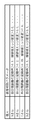
図16は、3つの識別器それぞれにおいて学習時に用いられるデータを表として示した図である。すなわち同図の表は、顔検出識別器に(Aさん、Bさんを含む)人の顔の検出を行わせるためのトレーニングを行う際に用いるデータ、Aさん識別器にAさんを識別するためのトレーニングを行う際に用いるデータ、Bさん識別器にBさんを識別するためのトレーニングを行う際に用いるデータを示すもので、あって、顔検出識別器を用いた顔検出の為のトレーニング時では、サンプルに用いる全ての人(Aさん、Bさん、その他の人)の顔の画像から求めた特徴ベクトルを正解データとして用い、顔の画像でない背景画像(非顔画像)を不正解データとして用いる。 FIG. 16 is a table showing data used in learning in each of the three classifiers as a table. In other words, the table in FIG. 8 is used to perform training for making the face detection classifier detect human faces (including Mr. A and Mr. B), and to identify Mr. A to the Mr. A classifier. The data used when performing training and the data used when training for identifying Mr. B in the Mr. B classifier are shown, and during training for face detection using the face detection classifier Then, feature vectors obtained from facial images of all persons (A, B, and others) used as samples are used as correct answer data, and background images (non-face images) that are not facial images are used as incorrect answer data. Use.
一方、Aさん識別器を用いたAさんの識別の為のトレーニング時ではAさんの顔画像から求めた特徴ベクトルを正解データとして用い、Aさん以外の人(同図では「Bさん」、「その他」)の顔画像から求めた特徴ベクトルを不正解データとして用いる。また、背景画像についてはトレーニング時には用いない。 On the other hand, at the time of training for identification of Mr. A using the Mr. A classifier, the feature vector obtained from the face image of Mr. A is used as correct answer data, and a person other than Mr. A ("Mr. B", " The feature vector obtained from the face image of “others”) is used as incorrect answer data. The background image is not used during training.
同様に、Bさん識別器を用いたBさんの識別の為のトレーニング時ではBさんの顔画像から求めた特徴ベクトルを正解データとして用い、Bさん以外の人(同図では「Aさん」、「その他」)の顔画像から求めた特徴ベクトルを不正解データとして用いる。また、背景画像についてはトレーニング時には用いない。 Similarly, at the time of training for identification of Mr. B using Mr. B's classifier, the feature vector obtained from Mr. B's face image is used as correct data, and a person other than Mr. B ("Mr. A", A feature vector obtained from the face image of “others”) is used as incorrect answer data. The background image is not used during training.
従って、3次特徴である目を検出する際に使用する2次特徴検出結果と、前述の個人判別に使用する2次特徴検出結果は一部共通するが、上述のように、顔検出時に目特徴を検出するための識別器(神経回路網)と個人判別を行う識別器は、識別器の種類の違い(すなわち、第1の実施形態で示した神経回路網とSVMや最近傍識別器との違い)だけではなく、トレーニングに使用されるデータの組が異なるため、共通する検出結果を使用してもそこから抽出される、識別に使用する情報が結果的に異なることになり、前者は目を検出し、後者は個人を判別することが出来る。 Accordingly, the secondary feature detection result used when detecting the eye that is the tertiary feature and the secondary feature detection result used for the personal discrimination described above are partly in common, but as described above, A classifier for detecting features (neural network) and a classifier for individual discrimination are different in the type of classifier (that is, the neural network shown in the first embodiment, the SVM, the nearest neighbor classifier, and the like). In addition to the difference in the data set used for training, the information used for identification, which is extracted from the same detection results, will differ as a result. The eyes can be detected and the latter can identify individuals.
なお、特徴ベクトルを作成する際に、顔検出部1302で得られた顔のサイズや向きが所定の範囲に入っていない場合は、中間検出結果保持部1303に保持されている中間処理結果に対して、回転補正やサイズ正規化を行うことも可能である。個人判別の識別器は、個人の細かな差異を識別するように設計されているため、サイズや回転を統一する方が、精度が向上する傾向がある。回転補正及びサイズ正規化は、中間検出結果保持部1303に保持されている中間処理結果を、個人判別部1304に入力するために、中間検出結果保持部1303から読み出すときに、行うことが出来る。
When creating a feature vector, if the face size and orientation obtained by the
以上の処理によって、顔の個人判別ができたので、個人判別部1304は、判定した個人に応じたコード(各個人に個別のコード)が、予め設定されたある個人に対応するコードに一致しているか否かを判断する(ステップS1405)。このコードは例えば番号であっても良いし、その表現方法は特に限定されるものではない。この判定結果は制御部1301に通知する。
Since the individual identification of the face has been completed by the above processing, the
ここで、ステップS1404までの処理により判定した個人が、予め設定された特定の個人と同じであった場合、例えば本実施形態の場合には、個人判別部1304が出力した「個人を示すコード」と、予め設定された特定の個人を示すコードとが一致した場合、制御部1301は画像保持部1305が保持している撮影画像を記録部1307に記録する。また、記録部1307がDVD−RAMやコンパクトフラッシュ(登録商標)である場合には、制御部1301は記録部1307を制御してDVD−RAMやコンパクトフラッシュ(登録商標)等の記憶媒体に撮影画像を記録する(ステップS1406)。また、記録する画像を、顔領域の画像としても良い。
Here, if the individual determined by the processing up to step S1404 is the same as the specific individual set in advance, for example, in the case of the present embodiment, the “code indicating the individual” output by the
一方、ステップS1404までの処理により判定した個人が、予め設定された特定の個人と同じではなかった場合、例えば本実施形態の場合には、個人判別部1304が出力した「個人を示すコード」と、予め設定された特定の個人を示すコードとが一致しなかった場合、制御部1301は撮像部1300を制御し、新たな画像を撮影させる。
On the other hand, if the individual determined by the processing up to step S1404 is not the same as the specific individual set in advance, for example, in the case of the present embodiment, the “code indicating the individual” output by the
なお、判定された個人が特定の表情であった場合にはその他にも、例えばステップS1406で、制御部1301が撮像部1300を制御して次の画像を撮影させつつ、撮影した画像を記録部1307に保持させるようにしても良い。また、制御部1301は表示部1306を制御して、撮影した画像を表示部1306に表示しても良い。
In addition, when the determined individual has a specific facial expression, for example, in step S1406, the
また、ステップS202で検出された顔領域が綺麗に撮像されるように、制御部1301が撮影部1300の撮影パラメータ(露出補正、自動焦点、色補正等、撮像系の撮像パラメータ)を設定し、再撮影を行ない、表示、記録するように動作させることも可能である。
In addition, the
上記説明したように、階層的に検出した局所特徴から最終的な検出対象を検出するアルゴリズムに基づいて、画像中の顔を検出すると、検出した顔領域に基づいて、露出補正や自動焦点、及び色補正等の処理が行なえるだけではなく、その顔検出処理の途中で得られる中間特徴検出結果である、目の候補の検出結果、及び口の候補の検出結果を用いて、個人の判別が、目や口を検出するための新たな検出処理を行うことなく可能になり、処理コストの増加を抑えつつ個人を検出し撮影することが出来るという効果がある。また、顔の位置やサイズなどの変動に強い個人認識が可能になる。 As described above, when a face in an image is detected based on an algorithm that detects a final detection target from hierarchically detected local features, exposure correction, autofocus, and In addition to being able to perform processing such as color correction, it is possible to identify individuals using the eye candidate detection result and the mouth candidate detection result, which are intermediate feature detection results obtained during the face detection process. It becomes possible without performing a new detection process for detecting eyes and mouth, and there is an effect that an individual can be detected and photographed while suppressing an increase in processing cost. In addition, personal recognition that is resistant to fluctuations in the position and size of the face is possible.
また、本実施形態に係る画像処理装置は図11に示す構成を備えるコンピュータとしても良い。また、図12に示す撮像装置における画像処理装置5111に適用しても良く、その場合、個人の判別結果に応じた撮影を行うことが可能となる。
Further, the image processing apparatus according to the present embodiment may be a computer having the configuration shown in FIG. Further, the present invention may be applied to the
[第5の実施形態]
本実施形態に係る画像処理装置は、同じ1つの画像に対して上記実施形態で説明した顔領域検出処理、第1乃至3の実施形態で説明した表情判別処理、第4の実施形態で説明した個人判別処理を行う。
[Fifth Embodiment]
The image processing apparatus according to the present embodiment is the face area detection process described in the above embodiment, the facial expression determination process described in the first to third embodiments, and the fourth embodiment described in the fourth embodiment. Perform personal identification processing.
図17は、本実施形態に係る画像処理装置の機能構成を示す図である。基本的には第1の実施形態に係る画像処理装置の構成に、第4の実施形態に係る画像処理装置の構成、及び統合部1708を加えたものとなっている。統合部1708を除く各部については上記実施形態において同じ名前の部分と同じ動作を行う。すなわち、撮像部1700からの画像は顔検出部1702、画像保持部1705、記録部1707、表示部1706に出力される。顔検出部1702は、上記実施形態と同様の顔領域検出処理を行い、検出処理結果を上記実施形態と同様に、表情検出部1704、個人判別部1714に出力する。また、その処理の途中で得られる中間検出結果を中間検出結果保持部1703に出力する。表情検出部1704は、第1の実施形態における表情検出部104と同様の処理を行う。個人判別部1714は、第4の実施形態における個人判別部1304と同様の処理を行う。
FIG. 17 is a diagram illustrating a functional configuration of the image processing apparatus according to the present embodiment. Basically, the configuration of the image processing apparatus according to the first embodiment is added with the configuration of the image processing apparatus according to the fourth embodiment and an
統合部1708は、顔検出部1702、表情検出部1704、個人判別部1714それぞれの処理結果のデータを受け、これを用いて、顔検出部1702が検出した顔が、ある特定の個人の顔であるか否か、そして特定の個人の顔である場合にはこの特定の顔がある特定の表情であるか否かの判断処理を行う。つまり、ある特定の個人が特定の表情であるかを判別する。
The
次に、上記各部の動作によって実行される、撮影画像中の顔が誰のもので、且つどのような表情であるのかを判別する為のメインの処理について、同処理のフローチャートを示す図18を用いて説明する。 Next, FIG. 18 which shows the flowchart of the process about the main process for discriminating who is the face in the photographed image and what kind of expression is executed by the operation of each part described above. It explains using.
ステップS1801からステップS1803の各ステップにおける処理は、それぞれ図14のステップS1401からステップS1403の各ステップにおける処理と同じであるので説明は省略する。すなわち、ステップS1801からステップS1803までの処理で、制御部1701と顔検出部1702とにより、撮像部1700からの画像に顔領域が存在するか否かを判断する。
The processing in each step from step S1801 to step S1803 is the same as the processing in each step from step S1401 to step S1403 in FIG. That is, in the processing from step S1801 to step S1803, the
存在する場合には処理をステップS1804に進め、図2のステップS204における処理と同じ処理を行うことで、表情検出部1704は、検出した顔領域中の顔の表情を判別する。
If it exists, the process proceeds to step S1804, and the facial
次にステップS1805では、図14のステップS1404における処理と同じ処理を行うことで、個人判別部1714は、検出した顔領域中の顔の個人判別を行う。
In step S1805, the
なお、ステップS1804,ステップS1805の各ステップにおける処理は、ステップS1802で検出した各顔毎に行う処理である。 Note that the processes in steps S1804 and S1805 are performed for each face detected in step S1802.
次に、ステップS1806では、統合部1708が、表情検出部1704から出力される「判定した表情に応じたコード」と、個人判別部1714から出力される「判定した個人に応じたコード」とを、各顔毎に管理する。
In step S 1806, the
図19は、この管理したデータの構成例を示す図である。上述の通り、表情検出部1704、個人判別部1714は共に、顔検出部1702が検出した各顔毎に表情判別、個人判別を行う。従って、統合部1708は、各顔毎に固有のID(同図では数字1,2,、)に関連付けて、「判定した表情に応じたコード」と、「判定した個人に応じたコード」とを管理する。例えば、「判定した表情に応じたコード」として「笑顔」というコードと、「判定した個人に応じたコード」として「A」というコードは、IDが1の顔に対するものであるので、これらのコードを1のIDに関連付けて管理する。これはIDが2の場合についても同様である。このようにして統合部1708は各コードを管理するためのテーブルデータ(例えば図19に示す構成を有する)を生成し、保持する。
FIG. 19 is a diagram showing a configuration example of the managed data. As described above, both the facial
そしてその後、統合部1708はステップS1806で、特定の個人が、ある特定の表情であるか否かをこのテーブルデータを参照することで、判断する。例えば、Aさんが笑っているのか否かを図19のテーブルデータを用いて判断するとすると、図19のテーブルデータではAさんは笑顔であるので、Aさんは笑っていると判断する。
After that, the
このようにして判断した結果、特定の個人が、ある特定の表情である場合には統合部1708はその旨を制御部1701に通知するので、処理をステップS1807に進め、図14のステップS1406と同じ処理を行う。
As a result of the determination, if a specific individual has a specific facial expression, the
尚本実施形態では顔検出処理と表情判別処理とを連続して行ったが、第2,3の実施形態で説明した方法を用いても良い。その場合、全体の処理時間を短縮することができる。 In the present embodiment, the face detection process and the facial expression determination process are continuously performed, but the method described in the second and third embodiments may be used. In that case, the entire processing time can be shortened.
以上の説明によって本実施形態によれば、画像から顔を検出し、個人を特定し、その表情を特定することで、多人数の中から所望の個人の所望の表情の写真を撮影すること、例えば、複数の子供の中から自分の子供の笑顔の瞬間を撮影することが可能となる。 As described above, according to the present embodiment, by detecting a face from an image, specifying an individual, and specifying the facial expression, taking a photograph of a desired facial expression of a desired individual from among a large number of people, For example, it becomes possible to take a picture of a smiling moment of a child from a plurality of children.
つまり、第1の実施形態で説明した撮像装置の画像処理装置に本実施形態に係る画像処理装置を適用すれば、個人判別処理、表情判別処理の両方を行うことができ、その結果、特定の個人が特定の表情をしたときの撮影を行うことが可能となる。さらに、特定の個人、表情を認識することで、人間と機械のインターフェースとしても使用することが出来る。 That is, if the image processing apparatus according to the present embodiment is applied to the image processing apparatus of the imaging apparatus described in the first embodiment, both the individual determination process and the facial expression determination process can be performed. It is possible to perform shooting when an individual has a specific expression. Furthermore, it can be used as an interface between humans and machines by recognizing specific individuals and facial expressions.
[第6の実施形態]
本実施形態では、第5の実施形態で説明した表情判別処理と個人判別処理とを、シーケンシャルに行う。これにより、より高精度に特定の個人の特定の表情を判別することができる。
[Sixth Embodiment]
In this embodiment, the facial expression determination process and the individual determination process described in the fifth embodiment are performed sequentially. Thereby, a specific facial expression of a specific individual can be determined with higher accuracy.
図20は、本実施形態に係る画像処理装置の機能構成を示す図である。同図に示した構成は、図18に示した第5の実施形態に係る画像処理装置の構成に対して、ほぼ同じであるが、個人判別部2014と表情判別部2004とが接続されている点、統合部1708の代わりに表情判別データ保持部2008が用いられている点が異なる。
FIG. 20 is a diagram illustrating a functional configuration of the image processing apparatus according to the present embodiment. The configuration shown in the figure is substantially the same as the configuration of the image processing apparatus according to the fifth embodiment shown in FIG. 18, but the
図21は本実施形態に係る画像処理装置が行うメインの処理のフローチャートである。以下同図を用いて、本実施形態に係る画像処理装置が行う処理について説明する。 FIG. 21 is a flowchart of main processing performed by the image processing apparatus according to the present embodiment. Hereinafter, processing performed by the image processing apparatus according to the present embodiment will be described with reference to FIG.
ステップS2101からステップS2103の各ステップにおける処理は、図18のステップS1801からステップS1803の各ステップにおける処理と同じであるので、その説明は省略する。 The processing in each step from step S2101 to step S2103 is the same as the processing in each step from step S1801 to step S1803 in FIG.
ステップS2104では、個人判別部2014がステップS1804と同様の処理を行うことで、個人判別処理を行う。なお、ステップS2104における処理は、ステップS1802で検出した各顔毎に行う処理である。次にステップS2105では、個人判別部2014は、ステップS2104で判別した顔がある特定の顔であるか否かを判断する。これは例えば、第5の実施形態で説明したように、管理情報(この場合、各顔固有のIDと、個人を示すコードとを関連付けるテーブル)を参照することで成されるものである。
In step S2104, the
そしてある特定の顔を示すコードと、判別した顔を示すコードとが一致する場合、すなわち、ステップS2104で判別した顔がある特定の顔である場合には個人判別部2014はその旨を表情検出部2004に通知し、そして処理をステップS2106に進め、表情判別処理2004は第1の実施形態と同様にして表情判別処理を行うのであるが、本実施形態では、表情検出部2004は表情判別処理を行う際には、表情判別データ保持部2008に保持されている「各個人に対応した表情判別データ」を用いる。
If the code indicating a specific face matches the code indicating the determined face, that is, if the face determined in step S2104 is a specific face, the
図22は、この表情判別データの構成例を示す図である。同図に示す如く、各個人毎に表情判別の為のパラメータをあらかじめ用意しておく。ここでパラメータとは、第1の実施形態で説明した「目の端点と口の端点の距離」「口の横幅の長さ」「目の横幅の長さ」のほかに、「頬の部分の影」や「目の下の影」等である。基本的には、第1の実施形態で説明したように、無表情の画像データから作成した参照データとの差分により、個人に依存しない表情認識は行えるが、個人に依存した特異な変化を検出することでより高精度の表情判別が行える。 FIG. 22 is a diagram showing a configuration example of the facial expression discrimination data. As shown in the figure, parameters for facial expression discrimination are prepared in advance for each individual. Here, the parameters are “the distance between the end of the eye and the end of the mouth”, “the length of the width of the mouth”, and “the length of the width of the eye” described in the first embodiment, For example, “shadow” and “shadow under eyes”. Basically, as described in the first embodiment, individual-independent facial expression recognition can be performed based on differences from reference data created from expressionless image data, but individual-dependent changes are detected. By doing so, more accurate facial expression discrimination can be performed.
例えば、ある特定の人物では、笑顔の時に、口が大きく横に伸びたり、頬の部分に影が出たり、目の下に影が出来るとすると、その人物に対する表情判別では、上記の特異な変化を使用することで、より精度の高い表情判別が可能になる。 For example, if a particular person has a smile with a large mouth, a shadow on his cheeks, or a shadow under his eyes, the distinctive change described above is used in facial expression discrimination for that person. By using it, facial expression discrimination with higher accuracy becomes possible.
従って表情検出部2004は、個人判別部2004が判別した顔を示すコードを受け、このコードに応じた表情判別のためのパラメータを表情判別データ保持部2008から読み出す。例えばこの表情判別データが図22に示す如く構成を有する場合、個人判別部2004が画像中のある顔をAさんのものであると判別し、Aさんを示すコードを表情検出部2004に出力すれば、表情検出部2004は、表情判別データ保持部2008から、Aさんに対応するパラメータ(目口間距離の変動率>1.1,頬領域エッジ密度3.0、、、を示すパラメータ)を読み出し、これを用いて表情判別処理を行う。
Accordingly, the facial
これにより表情検出部2004は、第1の実施形態で説明した処理を行うことで求めた目口間距離の変動率、頬領域エッジ密度等がこのパラメータが示す範囲に入っているのか否かをチェックすることで、更に高精度に表情判別を行うことができる。
As a result, the facial
図21に戻って、次に、表情検出部2004は、ステップS2106で判別した表情が、予め設定された特定の表情であるのか否かを判断する。これは、ステップS2106で判別した表情を示すコードと、予め設定された特定の表情を示すコードとが一致しているか否かを判別することで成されるものである。
Returning to FIG. 21, next, the facial
そして一致している場合には処理をステップS2108に進め、その旨を制御部1701に通知し、図14のステップS1406と同じ処理を行う。
If they match, the process proceeds to step S2108, and notification to that effect is sent to the
このように、各個人を特定してから、個人に合わせた表情認識を行うため、表情認識の精度が向上するという効果がある。また、画像から顔を検出し、個人を特定し、その表情を特定することで、多人数の中から所望の個人の所望の表情の写真を撮影すること、例えば、複数の子供の中から自分の子供の笑顔の瞬間を撮影することが可能となる。さらに、特定の個人、表情を認識することで、人間と機械のインターフェースとしても使用することが出来る。 In this way, facial expression recognition tailored to the individual is performed after each individual is specified, so that the accuracy of facial expression recognition is improved. In addition, by detecting a face from an image, specifying an individual, and specifying the facial expression, a photograph of the desired facial expression of the desired individual from among a large number of people can be taken, for example, from among a plurality of children It will be possible to shoot a moment of smiling children. Furthermore, it can be used as an interface between humans and machines by recognizing specific individuals and facial expressions.
また上記実施形態で「ある特定の個人」や「ある特定の表情」は所定の操作部を介して適宜ユーザが設定することも可能である。よって適宜設定するとそれに応じて当然、それらを示すコードもまた変更される。 In the above embodiment, the “certain specific person” and the “certain facial expression” can be appropriately set by the user via a predetermined operation unit. Therefore, if set appropriately, naturally, codes indicating them are also changed accordingly.
また上記実施形態では、被写体を顔としたが、これに限らず、乗り物や建物などであってもよい。 Moreover, in the said embodiment, although the to-be-photographed object was made into the face, not only this but a vehicle, a building, etc. may be sufficient.
[その他の実施形態]
本発明の目的は、前述した実施形態の機能を実現するソフトウェアのプログラムコードを記録した記録媒体(または記憶媒体)を、システムあるいは装置に供給し、そのシステムあるいは装置のコンピュータ(またはCPUやMPU)が記録媒体に格納されたプログラムコードを読み出し実行することによっても、達成されることは言うまでもない。この場合、記録媒体から読み出されたプログラムコード自体が前述した実施形態の機能を実現することになり、そのプログラムコードを記録した記録媒体は本発明を構成することになる。
[Other Embodiments]
An object of the present invention is to supply a recording medium (or storage medium) that records software program codes for realizing the functions of the above-described embodiments to a system or apparatus, and the computer of the system or apparatus (or CPU or MPU). Needless to say, this can also be achieved by reading and executing the program code stored in the recording medium. In this case, the program code itself read from the recording medium realizes the functions of the above-described embodiment, and the recording medium on which the program code is recorded constitutes the present invention.
また、コンピュータが読み出したプログラムコードを実行することにより、前述した実施形態の機能が実現されるだけでなく、そのプログラムコードの指示に基づき、コンピュータ上で稼働しているオペレーティングシステム(OS)などが実際の処理の一部または全部を行い、その処理によって前述した実施形態の機能が実現される場合も含まれることは言うまでもない。 Further, by executing the program code read by the computer, not only the functions of the above-described embodiments are realized, but also an operating system (OS) running on the computer based on the instruction of the program code. It goes without saying that a case where the function of the above-described embodiment is realized by performing part or all of the actual processing and the processing is included.
さらに、記録媒体から読み出されたプログラムコードが、コンピュータに挿入された機能拡張カードやコンピュータに接続された機能拡張ユニットに備わるメモリに書込まれた後、そのプログラムコードの指示に基づき、その機能拡張カードや機能拡張ユニットに備わるCPUなどが実際の処理の一部または全部を行い、その処理によって前述した実施形態の機能が実現される場合も含まれることは言うまでもない。 Furthermore, after the program code read from the recording medium is written into a memory provided in a function expansion card inserted into the computer or a function expansion unit connected to the computer, the function is based on the instruction of the program code. It goes without saying that the CPU or the like provided in the expansion card or the function expansion unit performs part or all of the actual processing and the functions of the above-described embodiments are realized by the processing.
本発明を上記記録媒体に適用する場合、その記録媒体には、先に説明したフローチャートに対応するプログラムコードが格納されることになる。 When the present invention is applied to the recording medium, program code corresponding to the flowchart described above is stored in the recording medium.
Claims (15)
前記入力手段が入力した画像からエッジを表す複数の局所特徴を検出し、当該検出した複数の局所特徴の組み合わせより顔の特徴を検出して、前記画像中の該顔の領域を特定する顔領域特定手段と、
前記顔領域特定手段により検出された前記顔の領域中の夫々の前記局所特徴の相対位置と、予め基準として設定した顔画像に対する夫々の前記局所特徴の相対位置との差、を用いて前記顔の属するカテゴリを判別する判別手段と
を備えることを特徴とする画像処理装置。 An input means for inputting an image including a face;
A face region that detects a plurality of local features representing edges from an image input by the input means, detects a facial feature from a combination of the detected plurality of local features, and identifies the region of the face in the image Specific means,
The difference between the relative position of each local feature in the face region detected by the face region specifying means and the relative position of each local feature with respect to a face image set in advance as a reference is used. An image processing apparatus comprising: a discriminating unit that discriminates a category to which the data belongs.
前記判別手段は、前記顔領域特定手段が特定した顔の領域中で、前記第1の局所特徴群から第nの局所特徴群までの何れかの局所特徴群の夫々の相対位置と、当該夫々の局所特徴の予め基準として求めた相対位置との差を用いて、前記顔の表情を判別することを特徴とする請求項3に記載の画像処理装置。 The face area specifying unit detects a first local feature group in the image input by the input unit, and each second local feature has a specific positional relationship in the first local feature group. By repeatedly performing a process of obtaining a second local feature group obtained by combining a plurality of first local features of a specific type from the image, the nth local feature group (n ≧ 2) is obtained,
The discrimination means includes a relative position of any one of the local feature groups from the first local feature group to the n-th local feature group in the face area specified by the face area specifying means, The image processing apparatus according to claim 3, wherein the facial expression is discriminated using a difference from a relative position obtained in advance as a reference of the local feature.
前記判別手段は、前記入力手段が画像を入力した時点で、その前段で前記入力手段が入力した画像を用いて前記顔領域特定手段が特定した顔の領域中の夫々の前記局所特徴の相対位置と、前記顔の領域中の夫々の前記局所特徴について予め基準として求めた相対位置と、のずれに基づいて前記顔の表情を判別する処理を行うことを特徴とする請求項3に記載の画像処理装置。 The input means performs a process of inputting images continuously by continuously performing a process of inputting a next image when the face area specifying means completes the process of specifying a face area,
The discrimination means is a relative position of each local feature in the face area specified by the face area specifying means using the image input by the input means at the previous stage when the input means inputs an image. 4. The image according to claim 3, wherein a process of discriminating the facial expression of the face is performed based on a difference between the local position in the face region and a relative position obtained in advance as a reference. 5. Processing equipment.
前記入力手段が入力したフレーム画像からエッジを表す複数の局所特徴を検出し、当該検出した複数の局所特徴の組み合わせより顔の特徴を検出して、前記フレーム画像中の顔の領域を特定する顔領域特定手段と、
前記入力手段が入力した第1のフレームの画像において前記顔領域特定手段が特定した顔の領域と位置的に対応する、前記第1のフレームよりも後のフレームである第2のフレームの画像における領域において、前記顔領域特定手段が検出した夫々の前記局所特徴の相対位置と、予め基準として設定した顔画像に対する夫々の前記局所特徴の相対位置と、の差に基づいて前記顔の表情を判別する判別手段と
を備えることを特徴とする画像処理装置。 Input means for continuously inputting frame images including a face;
A face for detecting a plurality of local features representing an edge from a frame image input by the input means, detecting a facial feature from a combination of the detected plurality of local features, and identifying a facial region in the frame image Area identification means;
In the image of the second frame, which is a frame after the first frame, corresponding to the position of the face area specified by the face area specifying means in the image of the first frame input by the input means. In the region, the facial expression is determined based on the difference between the relative position of each of the local features detected by the face region specifying unit and the relative position of each of the local features with respect to a face image set in advance as a reference. An image processing apparatus comprising: a determining unit that
前記入力手段が入力した画像からエッジを表す複数の局所特徴を検出し、当該検出した複数の局所特徴の組み合わせより顔の特徴を検出して、前記画像中の顔の領域を特定する顔領域特定手段と、
前記顔領域特定手段により検出された前記顔の領域中の夫々の前記局所特徴の検出結果と、それぞれの顔の画像から予め得た夫々の前記局所特徴の検出結果と、を用いて前記入力手段が入力した画像中の顔が誰の顔であるかを判別する第1の判別手段と
前記顔領域特定手段により特定された前記顔の領域中の夫々の前記局所特徴の相対位置と、予め基準として設定した顔画像に対する夫々の前記局所特徴の相対位置と、の差を用いて前記顔の表情を判別する第2の判別手段と
を備えることを特徴とする画像処理装置。 An input means for inputting an image including a face;
Face region specification for detecting a plurality of local features representing an edge from an image input by the input means, detecting a facial feature from a combination of the detected plurality of local features, and specifying a face region in the image Means,
The input means using the detection results of the local features in the face area detected by the face area specifying means and the detection results of the local features obtained in advance from the images of the faces. A first determination unit that determines who the face in the image input is, a relative position of each local feature in the face region specified by the face region specifying unit, and a reference in advance An image processing apparatus comprising: a second determination unit that determines a facial expression using a difference between the relative position of each local feature with respect to the face image set as.
前記入力工程で入力した画像からエッジを表す複数の局所特徴を検出し、当該検出した複数の局所特徴の組み合わせより顔の特徴を検出して、前記画像中の該顔の領域を特定する顔領域特定工程と、
前記顔領域特定工程で検出された前記顔の領域中の夫々の前記局所特徴の相対位置と、予め基準として設定した顔画像に対する夫々の前記局所特徴の相対位置との差、を用いて前記顔の属するカテゴリを判別する判別工程と
を備えることを特徴とする画像処理方法。 An input process for inputting an image including a face;
A face region that detects a plurality of local features representing edges from the image input in the input step, detects a facial feature from a combination of the detected plurality of local features, and identifies the region of the face in the image Specific process,
The difference between the relative position of each local feature in the face area detected in the face region specifying step and the relative position of each local feature with respect to a face image set in advance as a reference is used. And a discrimination step of discriminating a category to which the image belongs.
前記入力工程で入力したフレーム画像からエッジを表す複数の局所特徴を検出し、当該検出した複数の局所特徴の組み合わせより顔の特徴を検出して、前記フレーム画像中の顔の領域を特定する顔領域特定工程と、
前記入力工程で入力した第1のフレームの画像において前記顔領域特定工程で特定した顔の領域と位置的に対応する、前記第1のフレームよりも後のフレームである第2のフレームの画像における領域において、前記顔領域特定工程で検出した夫々の前記局所特徴の相対位置と、予め基準として設定した顔画像に対する夫々の前記局所特徴の相対位置との差、に基づいて前記顔の表情を判別する判別工程と
を備えることを特徴とする画像処理方法。 An input process for continuously inputting frame images including a face;
A face for detecting a plurality of local features representing an edge from the frame image input in the input step, detecting a facial feature from a combination of the detected plurality of local features, and identifying a facial region in the frame image Region identification process;
In an image of a second frame, which is a frame after the first frame, corresponding to the position of the face region specified in the face region specifying step in the image of the first frame input in the input step In the region, the facial expression is determined based on the difference between the relative position of each local feature detected in the face region specifying step and the relative position of each local feature with respect to a face image set in advance as a reference. An image processing method comprising: a determining step.
前記入力工程で入力した画像からエッジを表す複数の局所特徴を検出し、当該検出した複数の局所特徴の組み合わせより顔の特徴を検出して、前記画像中の顔の領域を特定する顔領域特定工程と、
前記顔領域特定工程で検出された前記顔の領域中の夫々の前記局所特徴の検出結果と、それぞれの顔の画像から予め得た夫々の前記局所特徴の検出結果と、を用いて前記入力工程で入力した画像中の顔が誰の顔であるかを判別する第1の判別工程と
前記顔領域特定工程で特定された前記顔の領域中の夫々の前記局所特徴の相対位置と、予め基準として設定した顔画像に対する夫々の前記局所特徴の相対位置との差、を用いて前記顔の表情を判別する第2の判別工程と
を備えることを特徴とする画像処理方法。 An input process for inputting an image including a face;
Face region specification for detecting a plurality of local features representing edges from the image input in the input step, detecting a facial feature from a combination of the detected plurality of local features, and specifying a face region in the image Process,
The input step using the detection result of each local feature in the face region detected in the face region specifying step and the detection result of each local feature obtained in advance from each face image A first discrimination step for discriminating who the face in the image inputted in step 1 is, a relative position of each local feature in the face region identified in the face region identification step, and a reference in advance And a second discrimination step of discriminating the facial expression using the difference between the relative position of each of the local features with respect to the face image set as.
Priority Applications (8)
| Application Number | Priority Date | Filing Date | Title |
|---|---|---|---|
| JP2004167588A JP4743823B2 (en) | 2003-07-18 | 2004-06-04 | Image processing apparatus, imaging apparatus, and image processing method |
| EP18157708.1A EP3358501B1 (en) | 2003-07-18 | 2004-07-16 | Image processing device, imaging device, image processing method |
| EP04747673.4A EP1650711B1 (en) | 2003-07-18 | 2004-07-16 | Image processing device, imaging device, image processing method |
| PCT/JP2004/010208 WO2005008593A1 (en) | 2003-07-18 | 2004-07-16 | Image processing device, imaging device, image processing method |
| CN200480024042.3A CN1839410B (en) | 2003-07-18 | 2004-07-16 | Image processor, imaging apparatus and image processing method |
| EP15151440.3A EP2955662B1 (en) | 2003-07-18 | 2004-07-16 | Image processing device, imaging device, image processing method |
| US11/330,138 US8515136B2 (en) | 2003-07-18 | 2006-01-12 | Image processing device, image device, image processing method |
| US13/944,038 US8942436B2 (en) | 2003-07-18 | 2013-07-17 | Image processing device, imaging device, image processing method |
Applications Claiming Priority (3)
| Application Number | Priority Date | Filing Date | Title |
|---|---|---|---|
| JP2003199357 | 2003-07-18 | ||
| JP2003199357 | 2003-07-18 | ||
| JP2004167588A JP4743823B2 (en) | 2003-07-18 | 2004-06-04 | Image processing apparatus, imaging apparatus, and image processing method |
Related Child Applications (1)
| Application Number | Title | Priority Date | Filing Date |
|---|---|---|---|
| JP2010211395A Division JP5517858B2 (en) | 2003-07-18 | 2010-09-21 | Image processing apparatus, imaging apparatus, and image processing method |
Publications (3)
| Publication Number | Publication Date |
|---|---|
| JP2005056387A JP2005056387A (en) | 2005-03-03 |
| JP2005056387A5 JP2005056387A5 (en) | 2007-07-19 |
| JP4743823B2 true JP4743823B2 (en) | 2011-08-10 |
Family
ID=34379747
Family Applications (1)
| Application Number | Title | Priority Date | Filing Date |
|---|---|---|---|
| JP2004167588A Expired - Fee Related JP4743823B2 (en) | 2003-07-18 | 2004-06-04 | Image processing apparatus, imaging apparatus, and image processing method |
Country Status (1)
| Country | Link |
|---|---|
| JP (1) | JP4743823B2 (en) |
Families Citing this family (33)
| Publication number | Priority date | Publication date | Assignee | Title |
|---|---|---|---|---|
| CN1839410B (en) * | 2003-07-18 | 2015-05-20 | 佳能株式会社 | Image processor, imaging apparatus and image processing method |
| JP4614391B2 (en) | 2005-06-15 | 2011-01-19 | キヤノン株式会社 | Image display method and image display apparatus |
| JP4926416B2 (en) | 2005-06-15 | 2012-05-09 | キヤノン株式会社 | Image display method, program, recording medium, and image display apparatus |
| US8542928B2 (en) | 2005-09-26 | 2013-09-24 | Canon Kabushiki Kaisha | Information processing apparatus and control method therefor |
| JP4799105B2 (en) * | 2005-09-26 | 2011-10-26 | キヤノン株式会社 | Information processing apparatus and control method therefor, computer program, and storage medium |
| JP4799104B2 (en) * | 2005-09-26 | 2011-10-26 | キヤノン株式会社 | Information processing apparatus and control method therefor, computer program, and storage medium |
| JP4218711B2 (en) | 2006-08-04 | 2009-02-04 | ソニー株式会社 | Face detection device, imaging device, and face detection method |
| JP4218712B2 (en) | 2006-08-04 | 2009-02-04 | ソニー株式会社 | Face detection device, imaging device, and face detection method |
| JP4973098B2 (en) * | 2006-09-28 | 2012-07-11 | ソニー株式会社 | Image processing apparatus, image processing method, and program |
| KR100860989B1 (en) | 2006-12-18 | 2008-09-30 | 삼성전자주식회사 | Method and apparatus for calculating similarity of face image, method and apparatus for retrieving face image, and method for synthesizing face image |
| JP4884251B2 (en) * | 2007-02-09 | 2012-02-29 | 富士フイルム株式会社 | Imaging apparatus, method, and program |
| JP4999570B2 (en) | 2007-06-18 | 2012-08-15 | キヤノン株式会社 | Facial expression recognition apparatus and method, and imaging apparatus |
| JP4853425B2 (en) | 2007-08-14 | 2012-01-11 | ソニー株式会社 | Imaging apparatus, imaging method, and program |
| JP4720810B2 (en) | 2007-09-28 | 2011-07-13 | 富士フイルム株式会社 | Image processing apparatus, imaging apparatus, image processing method, and image processing program |
| JP2012165407A (en) * | 2007-12-28 | 2012-08-30 | Casio Comput Co Ltd | Imaging apparatus and program |
| JP4986175B2 (en) | 2007-12-28 | 2012-07-25 | カシオ計算機株式会社 | Imaging apparatus and program |
| JP4914398B2 (en) | 2008-04-09 | 2012-04-11 | キヤノン株式会社 | Facial expression recognition device, imaging device, method and program |
| JP4535164B2 (en) * | 2008-04-09 | 2010-09-01 | ソニー株式会社 | Imaging apparatus, image processing apparatus, and image analysis method and program therefor |
| JP2014116033A (en) * | 2008-06-16 | 2014-06-26 | Canon Inc | Personal authentication device, personal authentication method, camera, program, and storage medium |
| JP2010027035A (en) | 2008-06-16 | 2010-02-04 | Canon Inc | Personal authentication equipment and personal authentication method |
| JP5106355B2 (en) * | 2008-11-13 | 2012-12-26 | キヤノン株式会社 | Facial expression determination device, control method thereof, imaging device, and program |
| JP5361524B2 (en) * | 2009-05-11 | 2013-12-04 | キヤノン株式会社 | Pattern recognition system and pattern recognition method |
| JP5709410B2 (en) * | 2009-06-16 | 2015-04-30 | キヤノン株式会社 | Pattern processing apparatus and method, and program |
| JP5510999B2 (en) * | 2009-11-26 | 2014-06-04 | Necカシオモバイルコミュニケーションズ株式会社 | Imaging apparatus and program |
| WO2011089872A1 (en) * | 2010-01-22 | 2011-07-28 | パナソニック株式会社 | Image management device, image management method, program, recording medium, and integrated circuit |
| CN103366782B (en) | 2012-04-06 | 2014-09-10 | 腾讯科技(深圳)有限公司 | Method and device automatically playing expression on virtual image |
| JP7110657B2 (en) * | 2018-03-26 | 2022-08-02 | カシオ計算機株式会社 | Image processing device, image processing method and program |
| JP6946231B2 (en) * | 2018-04-04 | 2021-10-06 | Kddi株式会社 | Object tracking device and object tracking method |
| JP7010779B2 (en) * | 2018-07-09 | 2022-01-26 | Kddi株式会社 | Image correction device and image correction method |
| JP7278088B2 (en) * | 2019-01-31 | 2023-05-19 | キヤノン株式会社 | Information processing device, information processing method, and program |
| JP7230710B2 (en) * | 2019-06-28 | 2023-03-01 | オムロン株式会社 | Image processing device, monitoring device, control system, image processing method, and program |
| CN110941332A (en) * | 2019-11-06 | 2020-03-31 | 北京百度网讯科技有限公司 | Expression driving method and device, electronic equipment and storage medium |
| CN116863529B (en) * | 2023-09-05 | 2023-11-07 | 诚峰智能光环境科技(江苏)有限公司 | Intelligent lamp control method based on facial expression recognition |
Family Cites Families (5)
| Publication number | Priority date | Publication date | Assignee | Title |
|---|---|---|---|---|
| JP2735028B2 (en) * | 1995-05-12 | 1998-04-02 | 日本電気株式会社 | Human face image matching device |
| JP4227257B2 (en) * | 1999-08-12 | 2009-02-18 | キヤノン株式会社 | camera |
| JP4291963B2 (en) * | 2000-04-13 | 2009-07-08 | 富士フイルム株式会社 | Image processing method |
| JP3992909B2 (en) * | 2000-07-03 | 2007-10-17 | 富士フイルム株式会社 | Personal image providing system |
| JP4846924B2 (en) * | 2001-05-31 | 2011-12-28 | キヤノン株式会社 | Pattern recognition device |
-
2004
- 2004-06-04 JP JP2004167588A patent/JP4743823B2/en not_active Expired - Fee Related
Also Published As
| Publication number | Publication date |
|---|---|
| JP2005056387A (en) | 2005-03-03 |
Similar Documents
| Publication | Publication Date | Title |
|---|---|---|
| JP5629803B2 (en) | Image processing apparatus, imaging apparatus, and image processing method | |
| JP4743823B2 (en) | Image processing apparatus, imaging apparatus, and image processing method | |
| KR102596897B1 (en) | Method of motion vector and feature vector based fake face detection and apparatus for the same | |
| EP1650711B1 (en) | Image processing device, imaging device, image processing method | |
| KR102147052B1 (en) | Emotional recognition system and method based on face images | |
| Dev et al. | Student attendance system using face recognition | |
| JP6664163B2 (en) | Image identification method, image identification device, and program | |
| JP5361530B2 (en) | Image recognition apparatus, imaging apparatus, and image recognition method | |
| JP5010905B2 (en) | Face recognition device | |
| CN107798279B (en) | Face living body detection method and device | |
| JP2006293644A (en) | Information processing device and information processing method | |
| Colombo et al. | Gappy PCA classification for occlusion tolerant 3D face detection | |
| JP2013218605A (en) | Image recognition device, image recognition method, and program | |
| Jindal et al. | Sign Language Detection using Convolutional Neural Network (CNN) | |
| Guha | A report on automatic face recognition: Traditional to modern deep learning techniques | |
| Curran et al. | The use of neural networks in real-time face detection | |
| JP4789526B2 (en) | Image processing apparatus and image processing method | |
| JP4061405B2 (en) | Face image classification registration device | |
| Hsu et al. | Facial expression recognition using Hough forest | |
| Chaudhry et al. | RECENT APPORACHES FOR FACEMASK FORGERY DETECTION | |
| Mahmood | Face detection by image discriminating | |
| CN112183422A (en) | Human face living body detection method and device based on space-time characteristics, electronic equipment and storage medium | |
| Seo et al. | Face Pose Estimation System by Combining Hybrid ICA-SVM Learning and 3D Modeling | |
| Arun et al. | Real World Real-time Automatic Recognition of Facial Expressions | |
| Hassani et al. | Evaluation of Individuals Identification using Facial recognition methods based on a Reference image |
Legal Events
| Date | Code | Title | Description |
|---|---|---|---|
| A521 | Written amendment |
Free format text: JAPANESE INTERMEDIATE CODE: A523 Effective date: 20070604 |
|
| A621 | Written request for application examination |
Free format text: JAPANESE INTERMEDIATE CODE: A621 Effective date: 20070604 |
|
| RD03 | Notification of appointment of power of attorney |
Free format text: JAPANESE INTERMEDIATE CODE: A7423 Effective date: 20070604 |
|
| A131 | Notification of reasons for refusal |
Free format text: JAPANESE INTERMEDIATE CODE: A131 Effective date: 20100720 |
|
| A521 | Written amendment |
Free format text: JAPANESE INTERMEDIATE CODE: A523 Effective date: 20100921 |
|
| A02 | Decision of refusal |
Free format text: JAPANESE INTERMEDIATE CODE: A02 Effective date: 20101015 |
|
| A521 | Written amendment |
Free format text: JAPANESE INTERMEDIATE CODE: A523 Effective date: 20110117 |
|
| A911 | Transfer to examiner for re-examination before appeal (zenchi) |
Free format text: JAPANESE INTERMEDIATE CODE: A911 Effective date: 20110411 |
|
| TRDD | Decision of grant or rejection written | ||
| A01 | Written decision to grant a patent or to grant a registration (utility model) |
Free format text: JAPANESE INTERMEDIATE CODE: A01 Effective date: 20110428 |
|
| A01 | Written decision to grant a patent or to grant a registration (utility model) |
Free format text: JAPANESE INTERMEDIATE CODE: A01 |
|
| A61 | First payment of annual fees (during grant procedure) |
Free format text: JAPANESE INTERMEDIATE CODE: A61 Effective date: 20110509 |
|
| FPAY | Renewal fee payment (event date is renewal date of database) |
Free format text: PAYMENT UNTIL: 20140520 Year of fee payment: 3 |
|
| R150 | Certificate of patent or registration of utility model |
Ref document number: 4743823 Country of ref document: JP Free format text: JAPANESE INTERMEDIATE CODE: R150 Free format text: JAPANESE INTERMEDIATE CODE: R150 |
|
| LAPS | Cancellation because of no payment of annual fees |