JP4227257B2 - camera - Google Patents
camera Download PDFInfo
- Publication number
- JP4227257B2 JP4227257B2 JP22807699A JP22807699A JP4227257B2 JP 4227257 B2 JP4227257 B2 JP 4227257B2 JP 22807699 A JP22807699 A JP 22807699A JP 22807699 A JP22807699 A JP 22807699A JP 4227257 B2 JP4227257 B2 JP 4227257B2
- Authority
- JP
- Japan
- Prior art keywords
- subject
- facial expression
- camera
- image
- person
- Prior art date
- Legal status (The legal status is an assumption and is not a legal conclusion. Google has not performed a legal analysis and makes no representation as to the accuracy of the status listed.)
- Expired - Fee Related
Links
Images


Description
【0001】
【発明の属する技術分野】
本発明は、被写体の状況を画像認識できるカメラに関するものである。
【0002】
【従来の技術】
1)従来、特開平7−128711号に示されているように、被写体となる人が撮影されていることを意識して不自然な表情にならないよう、該被写体である人に悟られず良好な撮影をするために、カメラのファインダを覗かなくともカメラの撮影レンズを正しく被写体に向けたときは、撮影者は音や光等で感知し撮影できる。或はカメラが被写体の方に向いたとき自動的に撮影を行うというものはあった。
【0003】
2)従来、特開平3−252775号,特開平8−249447号,特開平8−249453号,特開平10−255043等、顔の表情を認識する技術はいくつかあったが、カメラの機能に結び付けたものはなかった。
【0004】
3)野生動物撮影等で、カメラのファインダ視野内の特定位置に被写体が入ったときにカメラの撮影動作を行わせるために、この特定位置を挟むように赤外線投・受光装置を設置し、赤外線投・受光装置の間を被写体が横切った際に撮影指令をリモコン信号として発するというものはあった。
【0005】
4)また、特開昭57−115524号に示されるように、予め設定された距離位置へ、移動する被写体が到達したとき、これを自動的に合焦検出してシャッタレリーズ機構を作動させるというものはあった。
【0006】
【発明が解決しようとする課題】
しかしながら、上記1)の従来の技術では、被写体を撮影画面内に捉えることはできても、被写体となる人がしっかりカメラの方を向いているかどうか、また目を閉じていないか、更には目線がカメラの方を向いているかを、カメラの位置からかなりの距離離れた撮影者の目で判断しなくてはならず、直接カメラのファインダを覗いている場合に比べて失敗の確率が高くなってしまうという不都合があった。
【0007】
上記(2)の従来の顔の表情を認識する技術は、カメラの機能に応用されていないため、依然として撮影者が被写体となる人の表情を見て撮影するか否かを判断しなければならず、なるべく手間をかけず自動で撮影したいという人にとっては、煩わしいという不都合があった。また、良い表情を無人撮影したいという要望に答えられないという不都合もあった。更には、顔の表情に合った雰囲気を盛上げる効果を狙った演出も考えられてはいなかった。
【0008】
上記(3)の従来の技術では、赤外線投・受光装置を設置した場所でのみ、自動撮影が可能であり、撮影の自由度が無く、装置が大型化してしまうという不都合があった。
【0009】
上記(4)の従来の技術では、狙った被写体の近く或は急に飛び込んで別の被写体が存在した場合に、別の被写体が先に予め設定された距離位置へ到達してしまうと、狙った被写体にピントが合わず、別の被写体にピントが合った状態で撮影されてしまうという不都合があった。
【0015】
(発明の目的)
本発明の第1の目的は、被写体の顔の表情を認識し、顔の表情の判定結果に応じて、記録画面の明るさを変化させることのできるカメラを提供しようとするものである。
【0017】
本発明の第2の目的は、被写体の顔の表情を認識し、顔の表情の判定結果に応じて、表情に合った色に記録画面を変化させることのできるカメラを提供しようとするものである。
【0018】
【課題を解決するための手段】
上記第1の目的を達成するために、請求項1に記載の発明は、被写界の画像情報を検出する被写界像検出手段と、該被写界像検出手段からの画像情報を基に被写体の顔の表情を認識する表情認識手段と、該表情認識手段からの情報により、該顔の表情を判定する判定手段と、該判定手段の判定結果に応じて記録画面の明るさを変化させる画面明るさ変化手段と、該画面明るさ変化手段により変化された明るさの画面での被写体を記録する記録動作を行わせる制御手段とを有するカメラとするものである。
【0019】
また、上記第2の目的を達成するために、請求項2に記載の発明は、被写界の画像情報を検出する被写界像検出手段と、該被写界像検出手段からの画像情報を基に被写体の顔の表情を認識する表情認識手段と、該表情認識手段からの情報により、該顔の表情を判定する判定手段と、該判定手段の判定結果に応じて記録画面の色を変化させる画面色変化手段と、該画面色変化手段により変化された画面色での被写体を記録する記録動作を行わせる制御手段とを有するカメラとするものである。
【0026】
【発明の実施の形態】
以下、本発明を図面を参照しながら以下の実施の形態に基づいて詳細に説明する。
【0027】
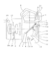
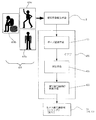
図1は本発明の実施の各形態に共通なカメラを示す中央縦断面図であり、図2は本発明の実施の第1の形態に係る主要部分の構成を示すブロック図である。
【0028】
これらの図において、1はカメラボディ、2は撮影レンズである。3は撮影光軸付近をハーフミラーとした主ミラーであり、主ミラー受板4(撮影光軸付近に開口を設けてある)に接着固定され、主ミラー受板4に設けられた軸4aを中心に図1のミラーダウンした観察状態から不図示のミラーアップした撮影光路外退避状態へ回動可能となっている。ミラーダウンした観察状態では、撮影レンズを通った被写体光は主ミラーで45度上へ反射され、ピント板5に像を結び、ペンタダハプリズム6で正立正像になり接眼レンズ7を通して撮影者に観察される。8はCCD(固体撮像素子)からなる被写界像検出手段であり、測光センサとしての役目もする。9は被写界像検出レンズであり、ピント板5に結ばれた像を被写界像検出手段8のセンサ面に結像させる。
【0029】
10はサブミラーであり、サブミラー受板11に接着支持され、サブミラー受板11の軸11aにより回動自在に支持される。サブミラー10は図1のミラーダウンした観察状態で主ミラー3の撮影光軸付近のハーフミラー部を通過した被写体光をカメラ下方に配置した焦点検出部へ導き、サブミラー受板4は不図示のミラーアップした撮影光路外退避状態で主ミラー受板4の撮影光軸付近の開口を塞ぐように作用する。12は焦点検出光学系のフィールドレンズ、13は反射ミラー、14は焦点検出光学系の二次結像レンズ、15は公知のパッシブオートフォーカス用位相差検出方式の焦点検出センサ、16はフォーカルプレーンシャッタ、17はレンズの絞り、18はフィルムである。
【0030】
図2に示す19は被写界像であり、19aは被写体である人物が正面を向いている状態を、19bは被写体である人物が横を向いている(正面を向いていない)状態を、それぞれ示している。20はカメラ全体を制御するCPUであり、その中に被写界像検出手段8からの画像情報を基に被写体の顔を認識する顔認識手段21や、該顔認識手段21からの情報により、顔が所定方向に向いているかを判定する判定手段22、更には該判定手段22の判定結果に応じて被写体記録動作を行う被写体記録動作制御手段23を有する。24はカメラ露光機能部であり、レンズの絞り17やフォーカルプレーンシャッタ16からなる。
【0031】
図1に示す25は、撮影光学系光軸近傍に設けられ、撮影光軸と同方向に近赤外光を投射するiRED、26は前記iRED25の投射に同期して不図示の進退機構によりCCDからなる被写界像検出手段8の前面に進入する近赤外光透過可視光カットフィルタ、27は日付やキャプションをフィルム背面より写し込ませるための公知のデートモジュールである。28は効果フィルタであり、不図示のアクチュエータと不図示の進退機構により撮影レンズの光束内への進入及び光束外への退避が可能に設けられ、少なくとも異なる2種類のフィルタが選択可能になっている。
【0032】
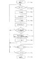
次に、上記構成におけるカメラの主要部分の動作について、図3のフローチャートにしたがって説明する。
【0033】
ステップ1にて不図示のメインスイッチがONされると、カメラに電源が供給され、撮影準備初期状態となる。そして、ステップ2において、CPU20はカメラの不図示のレリーズボタンが第1ストロークまで押されてスイッチSW−1がONしたかを判定し、ONであればステップ3へ進む。また、スイッチSW−1がOFFであればステップ10まで飛ぶ。
【0034】
ステップ3においては、CPU20はCCDからなる被写界像検出手段8よりの測光出力を取り込み、測光演算を行い、露光制御値を決定する。そして、次のステップ4において、公知の位相差検知方式のパッシブオートフォーカス装置の焦点検出センサ15の出力から焦点検出演算を行い、焦点合わせのための撮影レンズ駆動量を決定する。続くステップ5においては、上記ステップ4にて得られた撮影レンズ駆動量に基づいて撮影レンズ2の焦点調節用レンズ2aを駆動し、焦点調節する。そして、次のステップ6において、CPU20は撮影者が狙ったであろう被写体に焦点が合った被写界像を、CCDよりなる被写界像検出手段8に1フレームを1/30秒のビデオレートで順次取込ませる。
【0035】
次のステップ7においては、顔認識手段21が、取込まれた被写界像から人の顔を認識し、判定手段22により、認識された人の顔が正面を向いているかを判定する。図2の19aのように被写界像の被写体人物が正面を向いているのであればステップ8へ進み、19bのように正面を向いていなければステップ2へ戻る。
【0036】
なお、被写界像の中から正面を向いている人物像を抽出する方法(顔認識手段21と判定手段22によって行われる)は、以下に示す(a)〜(c)の手法が公知となっており、この実施の第1の形態ではそのうちの何れかの手法を用いるものとする。
【0037】
(a)テレビジョン学会誌Vol.49,No.6,pp.787−797(1995) の「顔領域抽出に有効な修正HSV表色系の提案」に示されるように、カラー画像をモザイク画像化し、肌色領域に着目して顔領域を抽出する手法。
【0038】
(b)電子情報通信学会誌Vol.J74−D−II,No.11,pp.1625−1627(1991) の「静止濃淡情景画像からの顔領域を抽出する手法」に示されるように、髪や目や口など正面人物像の頭部を構成する各部分に関する幾何学的な形状特徴を利用して正面人物像の頭部領域を抽出する手法。
【0039】
(c)画像ラボ 1991−11( 1991) の「テレビ電話用顔領域検出とその効果」に示されるように、動画像の場合、フレーム間の人物の微妙な動きによって発生する人物像の輪郭エッジを利用して正面人物像を抽出する手法。
【0040】
ステップ8へ進むと、ここでは上記ステップ3にて決定された露出制御値に基づいて被写体記録動作制御手段23は、絞り17の開口径とフォーカルプレーンシャッタ16のシャッタ秒時を制御し、フィルム18への露光を行う。そして、次のステップ9において、フィルムを1駒巻上げ、次の撮影に備え、前記フィルムの巻上げが終了するとステップ2へ戻る。
【0041】
上記ステップ2にてスイッチSW−1がOFFであるとしてステップ10へ進むと、ここではCPU20は所定時間を計時する測光タイマ(レリーズボタンを押してスイッチSW−1のONを保持せずとも露出設定変更できるよう、測光可能状態を所定時間保持するタイマ)の状態を見に行き、作動中であればステップ2へ戻る。また、所定時間が経過し不作動であればステップ11へ進み、ここでは不図示のメインスイッチの状態を見に行き、ONであればステップ2へ戻り、以下繰り返す。一方、OFFであればステップ12へ進み、カメラへの電源供給を遮断する。
【0042】
上記の実施の第1の形態によれば、被写体の顔の向きを認識し、顔が所定の方向、特に正面を向いた場合に被写体記録動作を行うので、撮影者に負担をかけず、被写体である人物がきちんとカメラの方を向いていないという失敗写真を防ぐ効果がある。
【0043】
(実施の第2の形態)
図4は本発明の実施の第2の形態に係るカメラの主要部分の回路構成を示すブロック図、図5は本発明の実施の第2の形態における主要部分の動作を示すフローチャートである。
【0044】
なお、これらの図において、上記実施の第1の形態と同じ部分はそのままの番号で示し、対応する部分に関しては上記実施の第1の形態の数字に200を加えた番号で示す。そして、ここでは上記実施の第1の形態と異なる個所のみを説明する。
【0045】
図4において、219は被写界像であり、219aは被写体である人物が目を開けてカメラの方に目線を向けている状態を、219bは被写体である人物が目を閉じている状態を、219cは被写体である人物は目を開けてはいるがカメラの方に目線を向けていない状態を、それぞれ示している。220はカメラ全体を制御するCPUであり、その中に被写界像検出手段8からの画像情報を基に被写体の目を認識する目認識手段221や、該目認識手段221からの情報により、目が特定の状態になっているか(例えば、目が開いているか、目線がカメラの方を向いているか)を判定する判定手段222、更には該判定手段222の判定結果に応じて被写体記録動作を行う制御手段223を有する。
【0046】
次に、上記構成におけるカメラの主要部分の動作について、図5のフローチャートにしたがって説明する。
【0047】
ステップ201からステップ205までは、上記実施の第1の形態における図3のステップ1からステップ5までと同じであり、その説明は省略する。
【0048】
ステップ206においては、CPU200は撮影者が狙ったであろう被写体に焦点が合った被写界像を、CCDからなる被写界像検出手段8に1フレームを1/30秒のビデオレートで順次取込ませる。また、瞳孔は入射した光を略同方向に反射する性質を持っており、顔の他の部分に比べて同軸照明状態の輝度が際立って大きく、弱い近赤外光を用いても瞳孔だけは明るく撮像される。従って、iRED25により近赤外光を被写体に投射し、近赤外光透過可視光カットフィルタ26を透過した被写界像を、被写界像検出手段8が1フレームを1/30秒のビデオレートで順次取込むようにさせると、より効果的に目の像が得られる。
【0049】
次のステップ207においては、目認識手段221が、取込まれた被写界像から人の目を認識し、判定手段222により、認識された人の目が開いているか、更には目線がカメラの方を向いているかを判定する。図4の219a或は219cのように、被写界像の被写体である人物の目が開いているのであればステップ208へ進み、219bのように目が閉じていればステップ202へ戻る。または、図4の219aのように被写界像の被写体である人物の目が開いて、しかも目線がカメラの方を向いているのであればステップ208へ進み、219cのように目を開けてはいるが、カメラの方に目線を向けていなかったり、219bのように目が閉じていればステップ202へ戻るようにしてもよい。
【0050】
なお、被写界像の中から人物の目(及び目線(視線)方向)を抽出する方法(目認識手段221と判定手段222によって行われる)は、以下に示す(d)〜(h)の手法が公知となっており、この実施の第2の形態ではそのうちの何れかの手法を用いるものとする。
【0051】
(d)特開平3−17696号に示されるように、目の領域を瞳孔中心を通る垂直線と水平線で分割し、分けられた領域の面積比を特徴量として視点位置を算出する手法。
【0052】
(e)特開平4−255015号に示されるように、視線の相対的な移動量を瞳の輪郭データを抽出し、瞳の中心座標の変化から求める手法。
【0053】
(f)特開平5−300601号に示されるように、赤外光を顔に投射し、特に反射率の高い眼球を抽出する手法。
【0054】
(g)特開平9−21611号に示されるように、近赤外光を撮影レンズと略同軸に被写体である人物に照射し、瞳孔の高輝度反射を検出し目を抽出する手法。
【0055】
(h)特開平9−251342号に示されるように、取得画像に対し領域分割を行い、各領域の色相、彩度の情報から顔領域を見つける。次に色相画像の2値化により、肌色部分とは異なる色属性を持つ目部分と口部分の候補を出し、目や口の濃淡パターンとの照合を行い、目領域と口領域を決める。そして検出した目、口に対してエッジ画像を生成し、エッジ画像を1次元の軸方向に垂直に写像し、目頭と左右の口元を検出する。更に目の切り出し画像を2値化し、黒画素の重心を瞳の重心とし、目頭点とから瞳のベクトルを求める。最後に顔の向きにおける目の位置より注視点を求める。という手法。
【0056】
ステップ208からステップ212までは、上記実施の第1の形態における図3のステップ8からステップ12までと同じであり、その説明は省略する。
【0057】
上記実施の第2の形態によれば、被写体の目の状態を認識し、目が所定の状態になった場合、特に目をしっかり開けて、カメラに目線が向いている場合に被写体記録動作を行うので、撮影者に負担をかけず、被写体である人物が目を閉じていたり、きちんとカメラの方を見ていないという失敗写真を防ぐ効果がある。
【0058】
(実施の第3の形態)
図6は本発明の実施の第3の形態に係るカメラの主要部分の回路構成を示すブロック図、図7は本発明の実施の第3の形態における主要部分の動作を示すフローチャートである。
【0059】
なお、これらの図において、上記実施の第1の形態と同じ部分はそのままの番号で示し、対応する部分に関しては上記実施の第1の形態の数字に300を加えた番号で示す。そして、ここでは上記実施の第1の形態と異なる個所のみを説明する。
【0060】
図6において、319は被写界像であり、319aは被写体である人物が無表情の状態を、319bは被写体である人物が笑っている喜びの状態を、319cは被写体である人物が泣いている悲しみの状態を、319dは被写体である人物の怒りの状態を、319eは被写体である人物の驚きの状態を、それぞれ示している。320はカメラ全体を制御するCPUであり、その中に被写界像検出手段8からの画像情報を基に被写体の表情を認識する表情認識手段321や、該表情認識手段321からの情報により、表情が特定の状態(例えば、喜び、悲しみ、怒り、驚きの状態)になっているかを判定する判定手段322、更には該判定手段322の判定結果に応じて被写体記録動作を行う制御手段323を有する。
【0061】
次に、上記構成におけるカメラの主要部分の動作について、図7のフローチャートにしたがって説明する。
【0062】
ステップ301からステップ306までは、上記実施の第1の形態における図3のステップ1からステップ6までと同様であり、その説明は省略する。
【0063】
ステップ307においては、表情認識手段321が、取込まれた被写界像から人の表情を認識し、判定手段322により、認識された人の表情が特定の状態(例えば、喜び、悲しみ、怒り、驚きの状態)になっているかを判定する。図6の319b〜319eのように、被写界像の被写体である人物の表情が喜び、悲しみ、怒り、驚きのいずれかの状態になっているのであればステップ308へ進み、そうでなければステップ302へ戻る。
【0064】
なお、被写界像の中から人物の表情を認識する方法(表情認識手段321と判定手段322によって行われる)は、以下に示す(i)〜(k)の手法が公知となっており、この実施の第3の形態ではそのうちの何れかの手法を用いるものとする。
【0065】
(i)特開平3−252775号に示されるように、筋肉の動きを測定するモジュールを備えており、このモジュールによって、顔の筋肉の動きの時間的変化のパターンに基づいて、学習モードでは標準表情パターンを学習記憶し、認識モードでは取込んだ画像による表情パターンと学習した標準表情パターンと比較し表情認識をするという手法。
【0066】
(j)特開平8−249447号に示されるように、顔の映像信号をウェーブレット変換し、それにより得られた空間周波数の平均電力を無表情のときの平均電力と比較し表情認識をするという手法。
【0067】
(k)特開平8−249453号,特開平10−255043号に示されるように、表情カテゴリとして、怒り、嫌悪、恐れ、悲しみ、幸福、驚きの合計6種類の基本表情を考え、無表情から各基本表情への時系列画像の処理を行う。例えば、人が相手の表情を読取るときに最も注目している領域である右目と口をそれぞれ含む2つの領域について、人の顔の動画像中の連続する2枚の画像からオプティカルフローアルゴリズムを用いて速度ベクトルを得る。この速度ベクトルの各成分に離散フーリエ変換を施し、フーリエ変換係数の低周波成分を特徴ベクトルとして抽出する。次に、HMM(隠れマルコフモデル)を用いて特徴ベクトルの生成確率を算出し、認識処理を行うという手法。
【0068】
ステップ308からステップ312までは、上記実施の第1の形態における図3のステップ8からステップ12までと同じであり、その説明は省略する。
【0069】
上記実施の第3の形態によれば、被写体の顔の表情を認識し、顔が所定の表情になった場合、特に喜び、悲しみ、怒り、驚きといった写真として面白い特徴的な表情になったときに被写体記録動作を行うので、撮影者に負担をかけず、無表情に近い平凡な写真を撮ることがなくなり、傑作写真が撮れる確率が高くなる効果がある。
【0070】
(実施の第4の形態)
図8は本発明の実施の第4の形態に係るカメラの主要部分の回路構成を示すブロック図、図9は本発明の実施の第2の形態における主要部分の動作を示すフローチャートである。
【0071】
なお、これらの図において、上記実施の第1の形態と同じ部分はそのままの番号で示し、対応する部分に関しては上記実施の第1の形態の数字に400を加えた番号で示す。そして、ここでは上記実施の第1の形態と異なる個所のみを説明する。
【0072】
図8において、419は被写界像であり、419aは被写体である人物が棒立ちの状態を、419bは被写体である人物が頬杖を突いて座っている状態を、419cは被写体である人物が片腕を上げる状態を、それぞれ示している。420はカメラ全体を制御するCPUであり、その中に被写界像検出手段8からの画像情報を基に被写体のポーズを認識するポーズ認識手段421や、該ポーズ認識手段421からの情報により、ポーズが特定の状態(例えば、頬杖を突いて座る、片腕を上げる等の状態)になっているかを判定する判定手段422、更には該判定手段422の判定結果に応じて被写体記録動作を行う制御手段423を有する。
【0073】
次に、上記構成におけるカメラの主要部分の動作について、図9のフローチャートにしたがって説明する。
【0074】
ステップ401からステップ406までは、上記実施の第1の形態における図3のステップ1からステップ6までと同じであり、その説明は省略する。
【0075】
ステップ407においては、ポーズ認識手段421が、取込まれた被写界像から人のポーズを認識し、判定手段422により、認識された人のポーズが特定の状態(例えば、頬杖を突いて座る、片腕を上げる等の状態)になっているかを判別する。図8の419b,419cのように、被写界像の被写体である人物のポーズが頬杖を突いて座る、片腕を上げる等の状態になっているのであればステップ408へ進み、そうでなければステップ402へ戻る。
【0076】
なお、被写界像の中からポーズを認識する方法(ポーズ認識手段421と判定手段422によって行われる)は、以下の(m)の手法が公知となっており、この実施の第4の形態では該手法を用いるものとする。
【0077】
(m)特開平7−57103号に示されるように、撮像された被写体の特定部位の輪郭を抽出し、記憶されたパターンと比較しポーズ認識をするという手法。
【0078】
ステップ408からステップ412までは、上記実施の第1の形態における図3のステップ8からステップ12までと同じであり、その説明は省略する。
【0079】
上記の実施の第4の形態によれば、被写体の姿勢(ポーズ)を認識し、被写体が所定の姿勢(ポーズ)になった場合、特に写真として面白い特徴的なポーズになったときに被写体記録動作を行うので、撮影者に負担をかけず、棒立ちのようなつまらないポーズの写真を撮ることがなくなり、傑作写真が撮れる確率が高くなる効果がある。
【0080】
(実施の第5の形態)
図10は本発明の実施の第5の形態に係るカメラの主要部分の回路構成を示すブロック図、図11は本発明の実施の第5の形態における主要部分の動作を示すフローチャートである。
【0081】
なお、これらの図において、上記実施の第1の形態と同じ部分はそのままの番号で示し、対応する部分に関しては上記実施の第1の形態の数字に500を加えた番号で示す。そして、ここでは上記実施の第1の形態と異なる個所のみを説明する。
【0082】
図10において、519は被写界像であり、519aは被写体である人物が棒立ちで静止している状態を、519bは被写体である人物が走り出した状態を、それぞれ示している。520はカメラ全体を制御するCPUであり、その中に被写界像検出手段8からの画像情報を基に被写体の動作を認識する動作認識手段521や、該動作認識手段521からの情報により、動作が特定の状態(例えば、走り出した状態)になっているかを判定する判定手段522、更には該判定手段522の判定結果に応じて被写体記録動作を行う制御手段523を有する。
【0083】
次に、上記構成におけるカメラの主要部分の動作について、図11のフローチャートにしたがって説明する。
【0084】
ステップ501からステップ506までは、上記実施の第1の形態における図3のステップ1からステップ6までと同じであり、その説明は省略する。
【0085】
ステップ507においては、動作認識手段521が、取込まれた被写界像から人の動作を認識し、判定手段522により、認識された人の動作が特定の状態(例えば、走り出した状態)になっているかを判別する。519bのように被写界像の被写体である人物の動作が走り出した状態になっているのであればステップ508へ進み、そうでなければステップ502へ戻る。
【0086】
なお、被写界像の中から動作を認識する方法(動作認識手段521と判定手段522によって行われる)は、以下に示す(n)の手法が公知となっており、この実施の第5の形態では該手法を用いるものとする。
【0087】
(n)特開平7−57103号に示されるように、撮像された被写体の特定部位の輪郭を抽出し、記憶されたパターンと比較し動作認識をするという手法。
【0088】
ステップ508からステップ512までは、上記実施の第1の形態における図3のステップ8からステップ12までと同じであり、その説明は省略する。
【0089】
上記実施の第5の形態によれば、被写体の動作を認識し、被写体が所定の動作を行った場合、特に写真として面白い特徴的な動作を行ったときに被写体記録動作を行うので、撮影者に負担をかけず、棒立ちに近いつまらない動作の写真を撮ることがなくなり、傑作写真が撮れる確率が高くなる効果がある。
【0090】
(実施の第6の形態)
図12は本発明の実施の第6の形態に係るカメラの主要部分の回路構成を示すブロック図、図13は本発明の実施の第6の形態における主要部分の動作を示すフローチャートである。
【0091】
なお、これらの図において、上記実施の第1の形態と同じ部分はそのままの番号で示し、対応する部分に関しては上記実施の第1の形態の数字に600を加えた番号で示す。そして、ここでは上記実施の第1の形態と異なる個所のみを説明する。
【0092】
図12において、619は被写界像であり、619aは被写体である人物が無表情の状態を、619bは被写体である人物が笑っている喜びの状態を、619cは被写体である人物が泣いている悲しみの状態を、619dは被写体である人物の怒りの状態を、619eは被写体である人物の驚きの状態を、それぞれ示している。620はカメラ全体を制御するCPUであり、その中に被写界像検出手段8からの画像情報を基に被写体の表情を認識する表情認識手段621や、該表情認識手段621からの情報により、表情が特定の状態(例えば、喜び、悲しみの状態)になっているかを判定する判定手段622、更には該判定手段622の判定結果に応じて被写体記録動作を行う制御手段623を有する。
【0093】
次に、上記構成におけるカメラの主要部分の動作について、図13のフローチャートにしたがって説明する。
【0094】
ステップ601からステップ606までは、上記実施の第1の形態における図3のステップ1からステップ6とまでと同じであり、その説明は省略する。
【0095】
ステップ607においては、表情認識手段621が、取込まれた被写界像から人の表情を認識し、判定手段622により、認識された人の表情が特定の状態(例えば、喜びの状態)になっているかを判別する。619bのように被写界像の被写体である人物の表情が喜びの状態になっているのであればステップ608へ進む。そうでなければステップ609へ進む。
【0096】
なお、被写界像の中から人物の表情を認識する方法(表情認識手段621と判定手段622によって行われる)は、上記実施の第3の形態と同じ公知の手法のように行われる。
【0097】
ステップ608においては、上記ステップ603にて決定された露出制御値に対し、撮影画面が明るくなるように(明るい雰囲気を出すように)プラスの露出補正をする。そして、次のステップ609において、表情認識手段621が、取込まれた被写界像から人の表情を認識し、判定手段622により、認識された人の表情が特定の状態(例えば、悲しみの状態)になっているかを判定する。図12の619cのように、被写界像の被写体である人物の表情が悲しみの状態になっているのであればステップ610へ進み、そうでなければステップ602へ戻る。
【0098】
なお、被写界像の中から人物の表情を認識する方法(表情認識手段621と判定手段622によって行われる)は、上記ステップ607での説明と同じく、前述した実施の第3の形態と同じ公知の手法により行うものとする。
【0099】
ステップ610においては、上記ステップ603にて決定された露出制御値に対し、撮影画面が暗くなるように(暗い雰囲気を出すように)マイナスの露出補正をする。
【0100】
ステップ611からステップ615までは、上記実施の第1の形態における図3のステップ8からステップ12とまでと同じであり、その説明は省略する。
【0101】
上記実施の第6の形態によれば、被写体の顔の表情を認識し、顔が所定の表情になった場合、特に喜び、悲しみといった写真の雰囲気として明るい・暗いがはっきりした特徴的な表情になったときに雰囲気に合わせて被写体記録画面の明るさを変化させるので、撮影者に負担をかけず、表情により醸し出される雰囲気を盛上げる効果がある。
【0102】
(実施の第7の形態)
図14は本発明の実施の第7の形態に係るカメラの主要部分の回路構成を示すブロック図、図15は本発明の実施の第7の形態における主要部分の動作を示すフローチャートである。
【0103】
なお、これらの図において、上記実施の第1の形態と同じ部分はそのままの番号で示し、対応する部分に関しては上記実施の第1の形態の数字に700を加えた番号で示す。そして、ここでは上記実施の第1の形態と異なる個所のみを説明する。
【0104】
図14において、719は被写界像であり、719aは被写体である人物が無表情の状態を、719bは被写体である人物が笑っている喜びの状態を、719cは被写体である人物が泣いている悲しみの状態を、719dは被写体である人物の怒りの状態を、719e は被写体である人物の驚きの状態を、それぞれ示している。720はカメラ全体を制御するCPUであり、その中に被写界像検出手段8からの画像情報を基に被写体の表情を認識する表情認識手段721や、表情認識手段721からの情報により、表情が特定の状態(例えば、喜び、悲しみ、怒りの状態)になっているかを判定する判定手段722、更には判定手段722の判定結果に応じて被写体記録動作とテキスト・キャラクタの記録動作を行う制御手段723を有する。27はテキスト・キャラクタ発生手段で日付やキャプションをフィルム背面より写し込ませるための公知のデートモジュールに相当する。729は撮影された被写体記録画像である。
【0105】
次に、上記構成におけるカメラの主要部分の動作について、図15のフローチャートにしたがって説明する。
【0106】
ステップ701からステップ706までは、上記実施の第1の形態における図3のステップ1からステップ6とまでと同じであり、その説明は省略する。
【0107】
ステップ707においては、表情認識手段721が、取込まれた被写界像から人の表情を認識し、判定手段722により、認識された人の表情が特定の状態(例えば、喜びの状態)になっているかを判定する。図14の719bのように、被写界像の被写体である人物の表情が喜びの状態になっているのであればステップ708へ進み、そうでなければステップ709へ進む。
【0108】
なお、被写界像の中から人物の表情を認識する方法(表情認識手段721と判定手段722によって行われる)は、上記実施の第3の形態と同じ公知の手法により行うものとする。
【0109】
ステップ708においては、テキスト・キャラクタ発生手段である日付やキャプションをフィルム背面より写し込ませるための公知のデートモジュール27を駆動し、図14の729bに示す「♪HAPPY♪」のような明るいイメージのテキストやキャラクタをフィルム18に写し込む。
【0110】
ステップ709においては、表情認識手段721が、取込まれた被写界像から人の表情を認識し、判定手段722により、認識された人の表情が特定の状態(例えば、悲しみの状態)になっているかを判定する。図14の719cのように、被写界像の被写体である人物の表情が悲しみの状態になっているのであればステップ710へ進み、そうでなければステップ711へ進む。
【0111】
なお、被写界像の中から人物の表情を認識する方法(表情認識手段721と判定手段722によって行われる)は、上記ステップ707での説明と同じく、実施の第3の形態と同じ公知の手法のように行われる。
【0112】
ステップ710においては、テキスト・キャラクタ発生手段である日付やキャプションをフィルム背面より写し込ませるための公知のデートモジュール27を駆動し、図14の729cに示す「★泣かないで★」のような慰めのテキストや、「…寂しいな…」「悲しいよー」といった悲しげなイメージのテキストやキャラクタをフィルム18に写し込む。
【0113】
ステップ711においては、表情認識手段721が、取込まれた被写界像から人の表情を認識し、判定手段722により、認識された人の表情が特定の状態(例えば、怒りの状態)になっているかを判定する。図14の719dのように、被写界像の被写体である人物の表情が怒りの状態になっているのであればステップ712へ進み、そうでなければステップ702へ戻る。
【0114】
なお、被写界像の中から人物の表情を認識する方法(表情認識手段721と判定手段722によって行われる)は、上記ステップ707での説明と同じく、実施の第3の形態と同じ公知の手法により行うものとする。
【0115】
ステップ712においては、テキスト・キャラクタ発生手段である日付やキャプションをフィルム背面より写し込ませるための公知のデートモジュール27を駆動し、「そんなに怒らないで」のような宥めるテキストや、図14の729dに示す「▲怒ったぞ!▲」といった怒りをイメージするテキストやキャラクタをフィルム18に写し込む。
【0116】
ステップ713からステップ717までは、上記実施の第1の形態における図3のステップ8からステップ12とまでと同じであり、その説明は省略する。
【0117】
上記実施の第7の形態によれば、被写体の顔の表情を認識し、顔が所定の表情になった場合、特に喜び、悲しみ、怒りといった写真の雰囲気がはっきりとした特徴を持った表情になったときに雰囲気に合わせたテキストやキャラクタを被写体と共に記録するので、撮影者に負担をかけず、表情により醸し出される雰囲気を盛上げる効果がある。
【0118】
(実施の第8の形態)
図16は本発明の実施の第8の形態に係るカメラの主要部分の回路構成を示すブロック図、図17は本発明の実施の第8の形態における主要部分の動作を示すフローチャートである。
【0119】
なお、これらの図において、上記実施の第1の形態と同じ部分はそのままの番号で示し、対応する部分に関しては上記実施の第1の形態の数字に800を加えた番号で示す。そして、ここでは上記実施の第1の形態と異なる個所のみを説明する。
【0120】
図16において、819は被写界像であり、819aは被写体である人物が無表情の状態を、819bは被写体である人物が笑っている喜びの状態を、819cは被写体である人物が泣いている悲しみの状態を、819dは被写体である人物の怒りの状態を、819e は被写体である人物の驚きの状態を、それぞれ示している。820はカメラ全体を制御するCPUであり、その中に被写界像検出手段8からの画像情報を基に被写体の表情を認識する表情認識手段821や、該表情認識手段821からの情報により、表情が特定の状態(例えば、喜び、悲しみ、怒りの状態)になっているかを判定する判定手段822、更には該判定手段822の判定結果に応じて被写体記録動作と画面色の記録動作を行う制御手段823を有する。28は画面色変化手段であり、効果フィルタが不図示のアクチュエータと不図示の進退機構により撮影レンズの光束内への進入及び光束外への退避が可能に設けられ、それぞれ黄・青・赤等の異なる色をベースとし、被写体の雰囲気に合った効果を出せるフィルタが選択可能になっている。829は撮影された被写体記録画像である。
【0121】
次に、上記構成におけるカメラの主要部分の動作について、図17のフローチャートにしたがって説明する。
【0122】
ステップ801からステップ806までは、上記実施の第1の形態における図3のステップ1からステップ6とまでと同じであり、その説明は省略する。
【0123】
ステップ807においては、表情認識手段821が、取込まれた被写界像から人の表情を認識し、判定手段822により、認識された人の表情が特定の状態(例えば、喜びの状態)になっているかを判定する。図16の819bのように、被写界像の被写体である人物の表情が喜びの状態になっているのであればステップ808へ進み、そうでなければステップ809へ進む。
【0124】
なお、被写界像の中から人物の表情を認識する方法(表情認識手段821と判定手段822によって行われる)は、上記実施の第3の形態と同じ公知の手法により行うものとする。
【0125】
ステップ808においては、画面色変化手段28の黄色をベースとした効果フィルタを撮影レンズの光束内へ進入させ、図16の829bに示すような太陽が燦燦と降り注ぐような明るいイメージの画面色をフィルム18に写し込む。
【0126】
ステップ809においては、表情認識手段821が、取込まれた被写界像から人の表情を認識し、判定手段822により、認識された人の表情が特定の状態(例えば、悲しみの状態)になっているかを判定する。図16の819cのように、被写界像の被写体である人物の表情が悲しみの状態になっているのであればステップ810へ進み、そうでなければステップ811へ進む。
【0127】
なお、被写界像の中から人物の表情を認識する方法(表情認識手段821と判定手段822によって行われる)は、上記ステップ807での説明と同じく、前述した実施の第3の形態と同じ公知の手法のように行われる。
【0128】
ステップ810においては、画面色変化手段28の青色をベースとした効果フィルタを撮影レンズの光束内へ進入させ、図16の829cに示すような、悲しげでブルーなイメージの画面色をフィルム18に写し込む。
【0129】
ステップ811においては、表情認識手段821が、取込まれた被写界像から人の表情を認識し、判定手段822により、認識された人の表情が特定の状態(例えば、怒りの状態)になっているかを判定する。図16の819dのように、被写界像の被写体である人物の表情が怒りの状態になっているのであればステップ812へ進み、そうでなければステップ802へ戻る。
【0130】
なお、被写界像の中から人物の表情を認識する方法(表情認識手段821と判定手段822によって行われる)は、上記ステップ807での説明と同じく、前述した実施の第3の形態と同じ公知の手法により行うものとする。
【0131】
ステップ812においては、画面色変化手段28の赤色をベースとした効果フィルタを撮影レンズの光束内へ進入させ、図16の829dに示すような、激しく燃え盛る炎の如き怒りをイメージする画面色をフィルム18に写し込む。
【0132】
ステップ813においては、上記ステップ803にて決定された露出制御値に基づいて被写体記録動作と画面色の記録動作を行う制御手段823は、絞り17の開口径とフォーカルプレーンシャッタ16のシャッタ秒時を制御し、フィルム18への露光を行う。そして、次のステップ814において、効果フィルタを撮影レンズの光束外へ退避させた後、フィルムを1駒巻上げ、次の撮影に備える。フィルムの巻上げ終了後はステップ802へ戻る。
【0133】
ステップ815からステップ817までは、上記実施の第1の形態における図3のステップ10からステップ12とまでと同じであり、その説明は省略する。
【0134】
なお、上記実施の第8の形態においては、画面色を変化させたが、同様に表情に合った雰囲気を画面に記録するため、画面を軟調効果にするソフトフォーカスや、霧のかかったようにするフォギーに代表されるような公知の光学フィルタで行われている特殊効果を出すことや、画面に模様を付けたりしても良い。
【0135】
以上の実施の第8の形態によれば、被写体の顔の表情を認識し、顔が所定の表情になった場合、特に喜び、悲しみ、怒りといった写真の雰囲気がはっきりとした特徴を持った表情になったときに雰囲気に合わせて変化させた画面色を被写体と共に記録するので、撮影者に負担をかけず、表情により醸し出される雰囲気を盛上げる効果がある。
【0136】
(変形例)
上記実施の各形態において、フィルム18の代わりにCCD(固体撮像素子)を設け、撮像素子駆動回路やディジタル画像処理回路、更には画像記憶手段等の公知の所謂ディジタルカメラの構成要素を設けることにより、銀塩カメラだけでなく、電子スチルカメラにも適応できる。例えば、上記実施の第6の形態の、被写体記録画面の明るさを変化させる手段として、絞りとシャッタにより露出を変化させる方法以外に、フィルムに代わるCCD(固体撮像素子)のゲインを変化させる方法もある。
【0137】
また、上記実施の第7の形態の、テキスト・キャラクタ発生手段として、テキスト・キャラクタのROMを有し、ディジタル画像処理の間に、公知の画像合成によりROM から読み出したテキストやキャラクタを被写体に重ね合わせて記録動作を行うことが考えられる。
【0138】
同様に、上記実施の第8の形態の、画面色変化手段として、ディジタル画像処理の間に、公知の色調整により画面色を変化させて被写体と共に記録することが考えられる。更には、公知の画像合成により特殊効果を出したり、模様を付けたりすることも可能である。
【0139】
【発明の効果】
以上説明したように、請求項1に記載の発明によれば、被写体の顔の表情を認識し、顔の表情の判定結果に応じて、記録画面の明るさを変化させることができるカメラを提供できるものである。
【0140】
また、請求項2に記載の発明によれば、被写体の顔の表情を認識し、顔の表情の判定結果に応じて、表情に合った色に記録画面を変化させることができるカメラを提供できるものである。
【図面の簡単な説明】
【図1】本発明の実施の各形態に共通なカメラを示す中央縦断面図である。
【図2】本発明の実施の第1の形態におけるカメラの主要部分の回路構成を示すブロック図である。
【図3】本発明の実施の第1の形態におけるカメラの主要部分の動作を示すフローチャートである。
【図4】本発明の実施の第2の形態におけるカメラの主要部分の回路構成を示すブロック図である。
【図5】本発明の実施の第2の形態におけるカメラの主要部分の動作を示すフローチャートである。
【図6】本発明の実施の第3の形態におけるカメラの主要部分の回路構成を示すブロック図である。
【図7】本発明の実施の第3の形態におけるカメラの主要部分の動作を示すフローチャートである。
【図8】本発明の実施の第4の形態におけるカメラの主要部分の回路構成を示すブロック図である。
【図9】本発明の実施の第4の形態におけるカメラの主要部分の動作を示すフローチャートである。
【図10】本発明の実施の第5の形態におけるカメラの主要部分の回路構成を示すブロック図である。
【図11】本発明の実施の第5の形態におけるカメラの主要部分の動作を示すフローチャートである。
【図12】本発明の実施の第6の形態におけるカメラの主要部分の回路構成を示すブロック図である。
【図13】本発明の実施の第6の形態におけるカメラの主要部分の動作を示すフローチャートである。
【図14】本発明の実施の第7の形態におけるカメラの主要部分の回路構成を示すブロック図である。
【図15】本発明の実施の第7の形態におけるカメラの主要部分の動作を示すフローチャートである。
【図16】本発明の実施の第8の形態におけるカメラの主要部分の回路構成を示すブロック図である。
【図17】本発明の実施の第8の形態におけるカメラの主要部分の動作を示すフローチャートである。
【符号の説明】
8 CCDからなる被写界像検出手段
20,220,320,420 CPU
21 顔認識手段
22,222,322,422 判定手段
23,223,323,423 被写体記録動作制御手段
24 カメラ露光機能部
27 テキスト・キャラクタ発生手段(デートモジュール)
28 画面色変化手段(効果フィルタ)
221 目認識手段
321,621,721,821 表情認識手段
421 ポーズ認識手段
520,620,720,820 CPU
521 動作認識手段、
522,622,722,822 判定手段
523,623 被写体記録動作制御手段
723 被写体&テキスト・キャラクタ記録動作制御手段
823 被写体&画面色記録動作制御手段[0001]
BACKGROUND OF THE INVENTION
The present invention relates to a camera capable of recognizing an object situation.
[0002]
[Prior art]
1) Conventionally, as shown in Japanese Patent Laid-Open No. 7-128711, it is good that the person who is the subject is not aware of it so that the person who is the subject is not aware of an unnatural expression. If the camera's shooting lens is correctly pointed at the subject without looking through the camera's viewfinder, the photographer can sense and shoot with sound or light. Or there was one that automatically took a picture when the camera was facing the subject.
[0003]
2) There have been several techniques for recognizing facial expressions, such as JP-A-3-252775, JP-A-8-249447, JP-A-8-249453, and JP-A-10-255043. There was nothing to tie.
[0004]
3) In order to cause the camera to perform shooting operations when a subject enters a specific position within the viewfinder field of the camera, such as for wildlife photography, an infrared projector / receiver is installed so as to sandwich this specific position. In some cases, a shooting command is issued as a remote control signal when a subject crosses between a light projecting / receiving device.
[0005]
4) Also, as disclosed in Japanese Patent Laid-Open No. 57-115524, when a moving subject reaches a preset distance position, it automatically detects the focus and activates the shutter release mechanism. There was a thing.
[0006]
[Problems to be solved by the invention]
However, in the conventional technique of 1) above, although the subject can be captured in the shooting screen, whether the subject person is firmly facing the camera, whether the eyes are closed, and further, The photographer must determine whether the camera is facing the camera with a large distance from the camera position, and the probability of failure is higher than when looking directly into the viewfinder of the camera. There was an inconvenience.
[0007]
The conventional technique for recognizing facial expressions in (2) above has not been applied to camera functions, so the photographer must still determine whether or not to shoot by looking at the facial expressions of the person who is the subject. However, there is an inconvenience that it is troublesome for those who want to shoot automatically without as much trouble as possible. There was also the inconvenience of not being able to answer the request to take a good facial expression unattended. In addition, there was no idea of directing the effect of enlivening the atmosphere that matched the facial expression.
[0008]
In the prior art (3), automatic photographing is possible only at the place where the infrared light projecting / receiving device is installed, and there is a disadvantage that there is no degree of photographing freedom and the apparatus becomes large.
[0009]
In the conventional technique of (4) above, when another subject exists near the target subject or suddenly jumps into the target location, if another subject reaches the previously set distance position, There is an inconvenience that a subject is not in focus and another subject is in focus.
[0015]
(Object of invention)
Of the present inventionFirstAn object of the present invention is to provide a camera capable of recognizing the facial expression of a subject and changing the brightness of a recording screen in accordance with the determination result of the facial expression.
[0017]
Of the present inventionSecondAn object of the present invention is to provide a camera that can recognize the facial expression of a subject and change the recording screen to a color that matches the facial expression according to the determination result of the facial expression.
[0018]
[Means for Solving the Problems]
In order to achieve the first object, the invention described in
[0019]
In order to achieve the second object, the invention according to
[0026]
DETAILED DESCRIPTION OF THE INVENTION
Hereinafter, the present invention will be described.The following with reference to the drawingsThis will be described in detail based on the embodiment.
[0027]
FIG. 1 is a central longitudinal sectional view showing a camera common to each embodiment of the present invention, and FIG. 2 is a block diagram showing a configuration of a main part according to the first embodiment of the present invention.
[0028]
In these figures, 1 is a camera body and 2 is a photographing lens.
[0029]
[0030]
2 is a scene image, 19a is a state in which the subject person is facing the front, 19b is a state in which the subject person is facing sideways (not facing the front), Each is shown.
[0031]
1 shown in FIG. 1 is provided in the vicinity of the optical axis of the photographic optical system, iRED projects near infrared light in the same direction as the photographic optical axis, and 26 is a CCD by an advancing / retracting mechanism (not shown) in synchronization with the projection of the
[0032]
Next, the operation of the main part of the camera in the above configuration will be described with reference to the flowchart of FIG.
[0033]
When a main switch (not shown) is turned on in
[0034]
In
[0035]
In the
[0036]
Note that the following methods (a) to (c) are known as methods for extracting a person image facing the front from the object scene image (performed by the face recognition means 21 and the determination means 22). In the first embodiment, any one of the methods is used.
[0037]
(A) As shown in “Proposal of Modified HSV Color System Effective for Face Area Extraction” in the Journal of the Institute of Television Engineers of Japan, Vol. 49, No. 6, pp. 787-797 (1995) To extract the face area by focusing on the skin color area.
[0038]
(B) As shown in “Method of extracting a face region from a still gray scene image” in the Journal of the Institute of Electronics, Information and Communication Engineers Vol. J74-D-II, No. 11, pp. 1625-1627 (1991) A method for extracting the head region of a front person image using geometric shape features of each part constituting the head part of the front person image such as the eyes and mouth.
[0039]
(C) In the case of a moving image, a contour edge of a person image generated by a subtle motion of a person between frames, as shown in “Video phone face area detection and its effect” in Image Lab 1991-11 (1991) A method to extract a frontal person image using.
[0040]
In
[0041]
If the switch SW-1 is OFF in
[0042]
According to the first embodiment described above, the direction of the face of the subject is recognized, and the subject recording operation is performed when the face is directed in a predetermined direction, particularly the front, so that the subject is not burdened. This has the effect of preventing failure photos where a person is not properly facing the camera.
[0043]
(Second Embodiment)
FIG. 4 is a block diagram showing the circuit configuration of the main part of the camera according to the second embodiment of the present invention, and FIG. 5 is a flowchart showing the operation of the main part in the second embodiment of the present invention.
[0044]
In these drawings, the same parts as those in the first embodiment are indicated by the numbers as they are, and the corresponding parts are indicated by numbers obtained by adding 200 to the numbers in the first embodiment. Only the points different from the first embodiment will be described here.
[0045]
In FIG. 4, 219 is an object scene image, 219a is a state in which the subject person is opening his eyes and looking toward the camera, and 219b is a state in which the subject person is closing his eyes.
[0046]
Next, the operation of the main part of the camera in the above configuration will be described with reference to the flowchart of FIG.
[0047]
Steps 201 to 205 are the same as
[0048]
In step 206, the CPU 200 sequentially converts the object scene image focused on the subject that the photographer was aiming into the object image detection means 8 comprising a CCD at a 1/30 second video rate. Let them be captured. In addition, the pupil has the property of reflecting the incident light in approximately the same direction, and the brightness of the coaxial illumination state is significantly higher than other parts of the face, so even if weak near infrared light is used, only the pupil is Brighter images are taken. Accordingly, the near-infrared light is projected onto the subject by the iRED 25 and the object scene image transmitted by the near-infrared light transmitting visible light cut
[0049]
In the next step 207, the eye recognizing means 221 recognizes the human eye from the captured object scene image, and the judging means 222 determines whether the recognized human eye is open or the line of sight is a camera. It is determined whether it is facing. If the eyes of the person who is the subject of the object scene image are open as in 219a or 219c in FIG. 4, the process proceeds to step 208. If the eyes are closed as in 219b, the process returns to step 202. Alternatively, if the eyes of the person who is the subject of the object scene image are opened as in 219a in FIG. 4 and the line of sight is facing the camera, the process proceeds to step 208, and the eyes are opened as in 219c. However, if the eyes are not directed toward the camera or the eyes are closed as in 219b, the process may return to step 202.
[0050]
In addition, a method (performed by the
[0051]
(D) A method of dividing the eye region into a vertical line and a horizontal line passing through the center of the pupil and calculating the viewpoint position using the area ratio of the divided regions as a feature amount as disclosed in Japanese Patent Laid-Open No. 3-17696.
[0052]
(E) As disclosed in Japanese Patent Laid-Open No. 4-255015, a method for obtaining the relative movement amount of the line of sight from changes in pupil center coordinates by extracting pupil contour data.
[0053]
(F) A method of projecting infrared light onto a face and extracting an eyeball having a particularly high reflectance as disclosed in Japanese Patent Laid-Open No. 5-300601.
[0054]
(G) As disclosed in Japanese Patent Laid-Open No. 9-21611, a method of irradiating a person who is a subject substantially coaxially with a photographing lens to detect high-intensity reflection of a pupil and extract an eye.
[0055]
(H) As shown in Japanese Patent Laid-Open No. 9-251342, the acquired image is divided into regions, and a face region is found from the hue and saturation information of each region. Next, by binarizing the hue image, candidates for the eye part and the mouth part having color attributes different from those of the skin color part are obtained, and the eye area and the mouth area are determined by collating with the shade patterns of the eyes and mouth. Then, an edge image is generated for the detected eyes and mouth, the edge image is mapped perpendicularly to the one-dimensional axial direction, and the head of the eye and the left and right mouths are detected. Further, the cut-out image of the eye is binarized, the center of gravity of the black pixel is set as the center of gravity of the pupil, and the pupil vector is obtained from the eye point. Finally, the gaze point is obtained from the eye position in the face direction. That technique.
[0056]
Steps 208 to 212 are the same as
[0057]
According to the second embodiment, the subject recording operation is performed when the eye state of the subject is recognized and the eye is in a predetermined state, particularly when the eye is opened firmly and the eye is facing the camera. As a result, the photographer is not burdened, and there is an effect of preventing a failure photograph in which a person who is a subject closes his eyes or does not properly look at the camera.
[0058]
(Third embodiment)
FIG. 6 is a block diagram showing the circuit configuration of the main part of a camera according to the third embodiment of the present invention, and FIG. 7 is a flowchart showing the operation of the main part in the third embodiment of the present invention.
[0059]
In these drawings, the same parts as those in the first embodiment are indicated by the numbers as they are, and the corresponding parts are indicated by numbers obtained by adding 300 to the numbers in the first embodiment. Only the points different from the first embodiment will be described here.
[0060]
In FIG. 6, 319 is an object scene image, 319a is a state in which a person who is a subject has no expression, 319b is a state of joy that a person who is a subject is laughing, and 319c is a person who is a subject crying. 319d shows the anger state of the person who is the subject, and 319e shows the surprise state of the person who is the subject.
[0061]
Next, the operation of the main part of the camera in the above configuration will be described with reference to the flowchart of FIG.
[0062]
Steps 301 to 306 are the same as
[0063]
In step 307, the facial
[0064]
Note that the following methods (i) to (k) are known as methods for recognizing a facial expression of a person from the object scene image (performed by the facial expression recognition means 321 and the determination means 322). In the third embodiment, any one of the methods is used.
[0065]
(I) As shown in Japanese Patent Laid-Open No. 3-252775, a module for measuring muscle movement is provided, and this module is used as a standard in the learning mode based on the temporal change pattern of facial muscle movement. A method that learns and stores facial expression patterns, and recognizes facial expressions in recognition mode by comparing them with the captured facial expression patterns.
[0066]
(J) As shown in Japanese Patent Laid-Open No. 8-249447, the facial image signal is subjected to wavelet transform, and the average power of the spatial frequency obtained thereby is compared with the average power when there is no expression to recognize facial expressions. Technique.
[0067]
(K) As shown in JP-A-8-249453 and JP-A-10-255043, the expression category is considered to be six types of basic facial expressions of anger, disgust, fear, sadness, happiness, and surprise. Process time-series images for each basic facial expression. For example, an optical flow algorithm is used from two consecutive images in a moving image of a person's face for two areas each including a right eye and a mouth, which are areas most noticed when a person reads a partner's facial expression. To get the velocity vector. Discrete Fourier transform is performed on each component of the velocity vector, and the low frequency component of the Fourier transform coefficient is extracted as a feature vector. Next, a method of calculating a feature vector generation probability using an HMM (Hidden Markov Model) and performing recognition processing.
[0068]
Steps 308 to 312 are the same as
[0069]
According to the third embodiment, when the facial expression of the subject is recognized and the face becomes a predetermined facial expression, especially when the facial expression is interesting, such as joy, sadness, anger, or surprise. In addition, since the subject recording operation is performed, there is no burden on the photographer, so that it is not necessary to take an ordinary photograph with almost no expression, and the probability that a masterpiece can be taken is increased.
[0070]
(Fourth embodiment)
FIG. 8 is a block diagram showing the circuit configuration of the main part of a camera according to the fourth embodiment of the present invention, and FIG. 9 is a flowchart showing the operation of the main part in the second embodiment of the present invention.
[0071]
In these drawings, the same parts as those in the first embodiment are indicated by the numbers as they are, and the corresponding parts are indicated by numbers obtained by adding 400 to the numbers in the first embodiment. Only the points different from the first embodiment will be described here.
[0072]
In FIG. 8, 419 is an object scene image, 419a is a person standing on a stick, 419b is a person sitting on a cheek cane, and 419c is a person on one arm. Each of these states is shown. A
[0073]
Next, the operation of the main part of the camera in the above configuration will be described with reference to the flowchart of FIG.
[0074]
Steps 401 to 406 are the same as
[0075]
In step 407, the
[0076]
As a method for recognizing a pose from an object scene image (performed by the
[0077]
(M) A method of extracting a contour of a specific part of an imaged subject and comparing it with a stored pattern to recognize a pose as disclosed in JP-A-7-57103.
[0078]
Steps 408 to 412 are the same as
[0079]
According to the fourth embodiment, the subject is recorded when the posture (pose) of the subject is recognized, and when the subject is in a predetermined posture (pose), particularly when the subject is in an interesting characteristic pose. Since the operation is performed, there is no burden on the photographer, and there is no need to take a picture of a boring pose like a stick standing, and there is an effect that the probability of taking a masterpiece photograph is increased.
[0080]
(Fifth embodiment)
FIG. 10 is a block diagram showing the circuit configuration of the main part of a camera according to the fifth embodiment of the present invention, and FIG. 11 is a flowchart showing the operation of the main part in the fifth embodiment of the present invention.
[0081]
In these drawings, the same parts as those in the first embodiment are indicated by the numbers as they are, and the corresponding parts are indicated by numbers obtained by adding 500 to the numbers in the first embodiment. Only the points different from the first embodiment will be described here.
[0082]
In FIG. 10, 519 is an object scene image, 519a shows a state where a person who is a subject is standing on a stick, and 519b shows a state where a person who is a subject starts running.
[0083]
Next, the operation of the main part of the camera in the above configuration will be described with reference to the flowchart of FIG.
[0084]
Steps 501 to 506 are the same as
[0085]
In step 507, the
[0086]
As a method for recognizing the motion from the object scene image (performed by the motion recognizing means 521 and the determining means 522), the following method (n) is known, and the fifth embodiment In the form, this method is used.
[0087]
(N) As disclosed in Japanese Patent Laid-Open No. 7-57103, a method of extracting a contour of a specific part of an imaged subject and comparing it with a stored pattern to recognize an operation.
[0088]
Steps 508 to 512 are the same as
[0089]
According to the fifth embodiment, the subject recording operation is performed when the subject performs a predetermined motion when the subject performs a predetermined motion, and particularly when the subject performs a characteristic motion that is interesting as a photograph. There is no need to take pictures of boring movements that are close to a stick, and the probability of taking a masterpiece is increased.
[0090]
(Sixth embodiment)
FIG. 12 is a block diagram showing the circuit configuration of the main part of a camera according to the sixth embodiment of the present invention, and FIG. 13 is a flowchart showing the operation of the main part in the sixth embodiment of the present invention.
[0091]
In these drawings, the same parts as those in the first embodiment are indicated by the numbers as they are, and the corresponding parts are indicated by numbers obtained by adding 600 to the numbers in the first embodiment. Only the points different from the first embodiment will be described here.
[0092]
In FIG. 12, 619 is an object scene image, 619a is a state in which the person who is the subject has no expression, 619b is a state of joy that the person who is the subject is laughing, and 619c is a person who is crying. 619d shows the anger state of the person who is the subject, and 619e shows the surprise state of the person who is the subject. A
[0093]
Next, the operation of the main part of the camera in the above configuration will be described with reference to the flowchart of FIG.
[0094]
Steps 601 to 606 are the same as
[0095]
In step 607, the facial
[0096]
Note that a method for recognizing a human facial expression from the object scene image (performed by the facial
[0097]
In step 608, positive exposure correction is performed with respect to the exposure control value determined in step 603 so that the photographing screen becomes bright (a bright atmosphere is created). Then, in the next step 609, the facial expression recognition means 621 recognizes the human facial expression from the captured scene image, and the judgment means 622 recognizes the recognized human facial expression in a specific state (for example, sadness). State). If the facial expression of the person who is the subject of the object scene image is in a sad state as indicated by 619c in FIG. 12, the process proceeds to step 610; otherwise, the process returns to step 602.
[0098]
Note that the method for recognizing a human facial expression from the object scene image (performed by the facial
[0099]
In step 610, negative exposure correction is performed on the exposure control value determined in step 603 so that the shooting screen becomes dark (a dark atmosphere is created).
[0100]
Steps 611 to 615 are the same as
[0101]
According to the sixth embodiment, when the facial expression of the subject is recognized and the facial expression becomes a predetermined facial expression, a bright / dark distinctive facial expression is obtained especially as a photo atmosphere such as joy and sadness. Since the brightness of the subject recording screen is changed according to the atmosphere when it becomes, there is an effect of enlivening the atmosphere created by the expression without placing a burden on the photographer.
[0102]
(Seventh embodiment)
FIG. 14 is a block diagram showing the circuit configuration of the main part of a camera according to the seventh embodiment of the present invention, and FIG. 15 is a flowchart showing the operation of the main part in the seventh embodiment of the present invention.
[0103]
In these drawings, the same parts as those in the first embodiment are indicated by the numbers as they are, and the corresponding parts are indicated by numbers obtained by adding 700 to the numbers in the first embodiment. Only the points different from the first embodiment will be described here.
[0104]
In FIG. 14, 719 is an object scene image, 719a is a state where a person who is a subject has no expression, 719b is a state of joy that a person who is a subject is laughing, and 719c is a person who is a subject crying. 719d shows the anger state of the person who is the subject, and 719e shows the surprise state of the person who is the subject.
[0105]
Next, the operation of the main part of the camera in the above configuration will be described with reference to the flowchart of FIG.
[0106]
Steps 701 to 706 are the same as
[0107]
In step 707, the facial
[0108]
Note that the method of recognizing a human facial expression from the object scene image (performed by the facial
[0109]
In step 708, a known
[0110]
In step 709, the facial
[0111]
Note that the method for recognizing the facial expression of a person from the object scene image (performed by the facial expression recognition means 721 and the determination means 722) is the same as that in the third embodiment, as in the above-described step 707. It is done like a technique.
[0112]
In step 710, a known
[0113]
In step 711, the facial
[0114]
Note that the method for recognizing the facial expression of a person from the object scene image (performed by the facial expression recognition means 721 and the determination means 722) is the same as that in the third embodiment, as in the above-described step 707. It shall be done by a method.
[0115]
In step 712, a known
[0116]
Steps 713 to 717 are the same as
[0117]
According to the seventh embodiment, when the facial expression of the subject is recognized and the facial expression becomes a predetermined facial expression, the facial expression of the photograph has a distinct characteristic, particularly joy, sadness, and anger. When this happens, text and characters that match the atmosphere are recorded together with the subject, so there is an effect of enlivening the atmosphere created by facial expressions without placing a burden on the photographer.
[0118]
(Eighth embodiment)
FIG. 16 is a block diagram showing the circuit configuration of the main part of the camera according to the eighth embodiment of the present invention, and FIG. 17 is a flowchart showing the operation of the main part in the eighth embodiment of the present invention.
[0119]
In these drawings, the same parts as those in the first embodiment are indicated by the numbers as they are, and the corresponding parts are indicated by numbers obtained by adding 800 to the numbers in the first embodiment. Only the points different from the first embodiment will be described here.
[0120]
In FIG. 16, 819 is an object scene image, 819a is a state where the person who is the subject has no expression, 819b is a state of joy that the person who is the subject is laughing, and 819c is a person who is the subject crying. 819d shows the anger state of the person who is the subject, and 819e shows the surprise state of the person who is the subject. A
[0121]
Next, the operation of the main part of the camera in the above configuration will be described with reference to the flowchart of FIG.
[0122]
Steps 801 to 806 are the same as
[0123]
In step 807, the facial
[0124]
Note that the method of recognizing a human facial expression from the object scene image (performed by the facial
[0125]
In step 808, the effect filter based on yellow of the screen color changing means 28 is made to enter the luminous flux of the photographing lens, and the screen color of a bright image as the sun shines as shown in 829b of FIG. 18 is imprinted.
[0126]
In step 809, the facial
[0127]
Note that the method for recognizing a human facial expression from the object scene image (performed by the facial
[0128]
In step 810, the blue color-based effect filter of the screen color changing means 28 is caused to enter the luminous flux of the photographing lens, so that the screen color of the sad blue image as shown in 829c of FIG. Copy.
[0129]
In step 811, the facial
[0130]
Note that the method for recognizing a human facial expression from the object scene image (performed by the facial
[0131]
In step 812, an effect filter based on red color of the screen color changing means 28 is entered into the light flux of the photographing lens, and a screen color that images an anger like a fiery flame as shown in 829d of FIG. 18 is imprinted.
[0132]
In step 813, the control means 823 that performs the subject recording operation and the screen color recording operation based on the exposure control value determined in step 803 described above determines the aperture diameter of the
[0133]
Steps 815 to 817 are the same as
[0134]
In the eighth embodiment, the screen color is changed. However, in order to record an atmosphere that matches the facial expression on the screen in the same way, the soft focus that softens the screen or the fog appears A special effect performed by a known optical filter represented by foggy or a pattern may be added to the screen.
[0135]
According to the eighth embodiment described above, when the facial expression of the subject is recognized and the face becomes a predetermined facial expression, a facial expression with a distinctive feature such as joy, sadness, and anger. Since the screen color changed in accordance with the atmosphere is recorded together with the subject when the image becomes, there is an effect of enlivening the atmosphere created by the expression without placing a burden on the photographer.
[0136]
(Modification)
In each of the above embodiments, a CCD (solid-state image sensor) is provided in place of the
[0137]
The seventh embodiment has a text / character ROM as the text / character generating means, and during the digital image processing, text and characters read from the ROM by known image composition are superimposed on the subject. It is conceivable to perform a recording operation together.
[0138]
Similarly, as the screen color changing means of the eighth embodiment, it is conceivable that during digital image processing, the screen color is changed by known color adjustment and recorded together with the subject. Furthermore, it is possible to produce a special effect or add a pattern by known image composition.
[0139]
【The invention's effect】
As described above, according to the first aspect of the present invention, the face of the subjectFacial expressionRecognize the faceFacial expressionDepending on the judgment result ofChanging the brightness of the recording screenIt is possible to provide a camera that can be used.
[0140]
According to the invention of
[Brief description of the drawings]
FIG. 1 is a central longitudinal cross-sectional view showing a camera common to each embodiment of the present invention.
FIG. 2 is a block diagram showing a circuit configuration of a main part of the camera according to the first embodiment of the present invention.
FIG. 3 is a flowchart showing the operation of the main part of the camera according to the first embodiment of the present invention.
FIG. 4 is a block diagram showing a circuit configuration of a main part of a camera according to a second embodiment of the present invention.
FIG. 5 is a flowchart showing the operation of the main part of the camera according to the second embodiment of the present invention.
FIG. 6 is a block diagram showing a circuit configuration of main parts of a camera according to a third embodiment of the present invention.
FIG. 7 is a flowchart showing the operation of the main part of the camera according to the third embodiment of the present invention.
FIG. 8 is a block diagram showing a circuit configuration of main parts of a camera according to a fourth embodiment of the present invention.
FIG. 9 is a flowchart showing the operation of the main part of the camera according to the fourth embodiment of the present invention.
FIG. 10 is a block diagram showing a circuit configuration of main parts of a camera according to a fifth embodiment of the present invention.
FIG. 11 is a flowchart showing the operation of the main part of the camera according to the fifth embodiment of the present invention.
FIG. 12 is a block diagram showing a circuit configuration of main parts of a camera according to a sixth embodiment of the present invention.
FIG. 13 is a flowchart showing the operation of the main part of the camera according to the sixth embodiment of the present invention.
FIG. 14 is a block diagram showing a circuit configuration of main parts of a camera according to a seventh embodiment of the present invention.
FIG. 15 is a flowchart showing operations of main parts of a camera according to a seventh embodiment of the present invention.
FIG. 16 is a block diagram showing a circuit configuration of main parts of a camera according to an eighth embodiment of the present invention.
FIG. 17 is a flowchart showing the operation of the main part of the camera according to the eighth embodiment of the present invention.
[Explanation of symbols]
8 Field image detection means comprising CCD
20, 220, 320, 420 CPU
21 Face recognition means
22, 222, 322, 422 determination means
23, 223, 323, 423 Subject recording operation control means
24 Camera exposure function section
27 Text / character generation means (date module)
28 Screen color changing means (effect filter)
221 Eye recognition means
321,621,721,821 Facial expression recognition means
421 Pose recognition means
520, 620, 720, 820 CPU
521 motion recognition means,
522, 622, 722, 822 determination means
523,623 Subject recording operation control means
723 Subject & text character recording operation control means
823 Subject & screen color recording operation control means
Claims (2)
Priority Applications (1)
| Application Number | Priority Date | Filing Date | Title |
|---|---|---|---|
| JP22807699A JP4227257B2 (en) | 1999-08-12 | 1999-08-12 | camera |
Applications Claiming Priority (1)
| Application Number | Priority Date | Filing Date | Title |
|---|---|---|---|
| JP22807699A JP4227257B2 (en) | 1999-08-12 | 1999-08-12 | camera |
Publications (3)
| Publication Number | Publication Date |
|---|---|
| JP2001051338A JP2001051338A (en) | 2001-02-23 |
| JP2001051338A5 JP2001051338A5 (en) | 2006-09-21 |
| JP4227257B2 true JP4227257B2 (en) | 2009-02-18 |
Family
ID=16870827
Family Applications (1)
| Application Number | Title | Priority Date | Filing Date |
|---|---|---|---|
| JP22807699A Expired - Fee Related JP4227257B2 (en) | 1999-08-12 | 1999-08-12 | camera |
Country Status (1)
| Country | Link |
|---|---|
| JP (1) | JP4227257B2 (en) |
Cited By (1)
| Publication number | Priority date | Publication date | Assignee | Title |
|---|---|---|---|---|
| WO2022195375A1 (en) | 2021-03-17 | 2022-09-22 | Ricoh Company, Ltd. | Image processing method, recording medium, image processing apparatus, and image-capturing apparatus |
Families Citing this family (53)
| Publication number | Priority date | Publication date | Assignee | Title |
|---|---|---|---|---|
| JP2002122934A (en) * | 2000-10-12 | 2002-04-26 | Olympus Optical Co Ltd | Camera |
| JP4675492B2 (en) * | 2001-03-22 | 2011-04-20 | 本田技研工業株式会社 | Personal authentication device using facial images |
| JP2003057530A (en) * | 2001-08-08 | 2003-02-26 | Olympus Optical Co Ltd | Focus detection unit and single lens reflex electronic camera |
| US7298412B2 (en) | 2001-09-18 | 2007-11-20 | Ricoh Company, Limited | Image pickup device, automatic focusing method, automatic exposure method, electronic flash control method and computer program |
| EP1650711B1 (en) | 2003-07-18 | 2015-03-04 | Canon Kabushiki Kaisha | Image processing device, imaging device, image processing method |
| JP4743823B2 (en) * | 2003-07-18 | 2011-08-10 | キヤノン株式会社 | Image processing apparatus, imaging apparatus, and image processing method |
| CN1839410B (en) * | 2003-07-18 | 2015-05-20 | 佳能株式会社 | Image processor, imaging apparatus and image processing method |
| JP2005060827A (en) * | 2003-07-29 | 2005-03-10 | Toshiba Ceramics Co Ltd | Plasma resistant member |
| US7920725B2 (en) | 2003-09-09 | 2011-04-05 | Fujifilm Corporation | Apparatus, method, and program for discriminating subjects |
| JP4541806B2 (en) * | 2003-09-09 | 2010-09-08 | 富士フイルム株式会社 | Object identification device and method, and program |
| JP4492273B2 (en) * | 2004-09-22 | 2010-06-30 | 株式会社ニコン | Imaging apparatus and program |
| JP5515192B2 (en) * | 2005-02-17 | 2014-06-11 | セイコーエプソン株式会社 | Image recording apparatus, image recording method, and control program |
| JP4639869B2 (en) * | 2005-03-14 | 2011-02-23 | オムロン株式会社 | Imaging apparatus and timer photographing method |
| JP4635742B2 (en) * | 2005-06-27 | 2011-02-23 | 株式会社ニコン | Imaging apparatus and imaging program |
| JP4626425B2 (en) | 2005-07-11 | 2011-02-09 | 富士フイルム株式会社 | Imaging apparatus, imaging method, and imaging program |
| JP2007067560A (en) * | 2005-08-29 | 2007-03-15 | Canon Inc | Imaging apparatus and its control method, computer program and recording medium |
| JP4513699B2 (en) * | 2005-09-08 | 2010-07-28 | オムロン株式会社 | Moving image editing apparatus, moving image editing method and program |
| EP1962497B1 (en) | 2005-11-25 | 2013-01-16 | Nikon Corporation | Electronic camera and image processing device |
| JP5164327B2 (en) * | 2005-12-26 | 2013-03-21 | カシオ計算機株式会社 | Imaging apparatus and program |
| JP2007184787A (en) * | 2006-01-06 | 2007-07-19 | Fujifilm Corp | Digital camera |
| JP4775066B2 (en) * | 2006-03-28 | 2011-09-21 | カシオ計算機株式会社 | Image processing device |
| JP4891674B2 (en) * | 2006-06-30 | 2012-03-07 | オリンパスイメージング株式会社 | camera |
| JP4240108B2 (en) | 2006-10-31 | 2009-03-18 | ソニー株式会社 | Image storage device, imaging device, image storage method, and program |
| JP4757173B2 (en) | 2006-11-17 | 2011-08-24 | キヤノン株式会社 | Imaging apparatus, control method thereof, and program |
| JP2008160280A (en) * | 2006-12-21 | 2008-07-10 | Sanyo Electric Co Ltd | Imaging apparatus and automatic imaging method |
| JP4789825B2 (en) * | 2007-02-20 | 2011-10-12 | キヤノン株式会社 | Imaging apparatus and control method thereof |
| US7995106B2 (en) | 2007-03-05 | 2011-08-09 | Fujifilm Corporation | Imaging apparatus with human extraction and voice analysis and control method thereof |
| JP2008263422A (en) * | 2007-04-12 | 2008-10-30 | Yasumasa Muto | Imaging apparatus and imaging method |
| JP4908321B2 (en) * | 2007-06-14 | 2012-04-04 | 富士フイルム株式会社 | Imaging device |
| EP2015568B1 (en) | 2007-06-14 | 2019-02-13 | FUJIFILM Corporation | Digital image pickup apparatus |
| JP4513843B2 (en) | 2007-09-10 | 2010-07-28 | カシオ計算機株式会社 | Imaging apparatus and program |
| JP4952462B2 (en) * | 2007-09-12 | 2012-06-13 | ソニー株式会社 | Imaging apparatus and imaging method |
| JP4803147B2 (en) * | 2007-09-27 | 2011-10-26 | カシオ計算機株式会社 | Imaging apparatus, image generation method, and program |
| KR101396326B1 (en) | 2007-10-12 | 2014-05-16 | 삼성전자주식회사 | Method of controlling digital image processing apparatus for face detection, and image processing apparatus adopting the method |
| KR100840023B1 (en) * | 2007-11-13 | 2008-06-20 | (주)올라웍스 | Method and system for adjusting pose at the time of taking photos of himself or herself |
| JP2012165407A (en) * | 2007-12-28 | 2012-08-30 | Casio Comput Co Ltd | Imaging apparatus and program |
| JP4986175B2 (en) | 2007-12-28 | 2012-07-25 | カシオ計算機株式会社 | Imaging apparatus and program |
| JP4518157B2 (en) | 2008-01-31 | 2010-08-04 | カシオ計算機株式会社 | Imaging apparatus and program thereof |
| JP2009223527A (en) * | 2008-03-14 | 2009-10-01 | Seiko Epson Corp | Image processor, image processing method, and computer program for image processing |
| JP5042896B2 (en) * | 2008-03-25 | 2012-10-03 | オリンパス株式会社 | Image processing apparatus and image processing program |
| JP2009260630A (en) * | 2008-04-16 | 2009-11-05 | Olympus Corp | Image processor and image processing program |
| JP5361547B2 (en) * | 2008-08-07 | 2013-12-04 | キヤノン株式会社 | Imaging apparatus, imaging method, and program |
| JP5100621B2 (en) * | 2008-11-12 | 2012-12-19 | キヤノン株式会社 | Imaging device |
| JP5402018B2 (en) | 2009-01-23 | 2014-01-29 | 株式会社ニコン | Display device and imaging device |
| JP2010176224A (en) * | 2009-01-27 | 2010-08-12 | Nikon Corp | Image processor and digital camera |
| JP5093178B2 (en) * | 2009-04-06 | 2012-12-05 | 株式会社ニコン | Electronic camera |
| JP2011097502A (en) * | 2009-11-02 | 2011-05-12 | Panasonic Corp | Photographing control device, and photographing control method |
| JP5755012B2 (en) | 2011-04-21 | 2015-07-29 | キヤノン株式会社 | Information processing apparatus, processing method thereof, program, and imaging apparatus |
| JP5891874B2 (en) * | 2012-03-16 | 2016-03-23 | カシオ計算機株式会社 | Imaging apparatus and program |
| CN109218618A (en) * | 2018-10-12 | 2019-01-15 | 上海思依暄机器人科技股份有限公司 | Video image grasp shoot method and video image capture robot |
| JP2021057815A (en) | 2019-09-30 | 2021-04-08 | キヤノン株式会社 | Imaging apparatus, control method of the same, program, and storage medium |
| JP2021150760A (en) * | 2020-03-18 | 2021-09-27 | キヤノン株式会社 | Imaging apparatus and method for controlling the same |
| JP2022070684A (en) | 2020-10-27 | 2022-05-13 | キヤノン株式会社 | Imaging device, control method thereof, and program |
-
1999
- 1999-08-12 JP JP22807699A patent/JP4227257B2/en not_active Expired - Fee Related
Cited By (1)
| Publication number | Priority date | Publication date | Assignee | Title |
|---|---|---|---|---|
| WO2022195375A1 (en) | 2021-03-17 | 2022-09-22 | Ricoh Company, Ltd. | Image processing method, recording medium, image processing apparatus, and image-capturing apparatus |
Also Published As
| Publication number | Publication date |
|---|---|
| JP2001051338A (en) | 2001-02-23 |
Similar Documents
| Publication | Publication Date | Title |
|---|---|---|
| JP4227257B2 (en) | camera | |
| US9147106B2 (en) | Digital camera system | |
| US8180106B2 (en) | Image capturing apparatus and image capturing method | |
| JP4196714B2 (en) | Digital camera | |
| JP4583527B2 (en) | How to determine eye position | |
| US8212894B2 (en) | Electronic camera having a face detecting function of a subject | |
| US7248300B1 (en) | Camera and method of photographing good image | |
| KR100924685B1 (en) | Imaging apparatus and control method thereof | |
| JP4829186B2 (en) | Imaging device | |
| US8159561B2 (en) | Digital camera with feature extraction device | |
| US20040119851A1 (en) | Face recognition method, face recognition apparatus, face extraction method, and image pickup apparatus | |
| KR20100048600A (en) | Image photography apparatus and method for proposing composition based person | |
| JP2001330882A (en) | Camera with subject recognizing function | |
| JP2004317699A (en) | Digital camera | |
| JP2004320286A (en) | Digital camera | |
| JP2002153445A (en) | Iris recognition device | |
| JP2004320285A (en) | Digital camera | |
| JP2003224761A (en) | Imaging apparatus | |
| JP2009117975A (en) | Image pickup apparatus and method | |
| JP2010273280A (en) | Imaging apparatus | |
| JP2000347277A (en) | Camera and method of pick up | |
| JP5109864B2 (en) | Electronic still camera | |
| JP2010177991A (en) | Digital camera | |
| JPH0884280A (en) | Head mount type video camera | |
| JP5055569B2 (en) | Color imaging apparatus and image processing program |
Legal Events
| Date | Code | Title | Description |
|---|---|---|---|
| A521 | Request for written amendment filed |
Free format text: JAPANESE INTERMEDIATE CODE: A523 Effective date: 20060803 |
|
| A621 | Written request for application examination |
Free format text: JAPANESE INTERMEDIATE CODE: A621 Effective date: 20060803 |
|
| A131 | Notification of reasons for refusal |
Free format text: JAPANESE INTERMEDIATE CODE: A131 Effective date: 20080902 |
|
| A521 | Request for written amendment filed |
Free format text: JAPANESE INTERMEDIATE CODE: A523 Effective date: 20081029 |
|
| TRDD | Decision of grant or rejection written | ||
| A01 | Written decision to grant a patent or to grant a registration (utility model) |
Free format text: JAPANESE INTERMEDIATE CODE: A01 Effective date: 20081125 |
|
| A01 | Written decision to grant a patent or to grant a registration (utility model) |
Free format text: JAPANESE INTERMEDIATE CODE: A01 |
|
| A61 | First payment of annual fees (during grant procedure) |
Free format text: JAPANESE INTERMEDIATE CODE: A61 Effective date: 20081128 |
|
| FPAY | Renewal fee payment (event date is renewal date of database) |
Free format text: PAYMENT UNTIL: 20111205 Year of fee payment: 3 |
|
| R150 | Certificate of patent or registration of utility model |
Free format text: JAPANESE INTERMEDIATE CODE: R150 |
|
| FPAY | Renewal fee payment (event date is renewal date of database) |
Free format text: PAYMENT UNTIL: 20121205 Year of fee payment: 4 |
|
| FPAY | Renewal fee payment (event date is renewal date of database) |
Free format text: PAYMENT UNTIL: 20131205 Year of fee payment: 5 |
|
| LAPS | Cancellation because of no payment of annual fees |