JP4215741B2 - 回路遮断器 - Google Patents
回路遮断器 Download PDFInfo
- Publication number
- JP4215741B2 JP4215741B2 JP2005119150A JP2005119150A JP4215741B2 JP 4215741 B2 JP4215741 B2 JP 4215741B2 JP 2005119150 A JP2005119150 A JP 2005119150A JP 2005119150 A JP2005119150 A JP 2005119150A JP 4215741 B2 JP4215741 B2 JP 4215741B2
- Authority
- JP
- Japan
- Prior art keywords
- fixed contact
- load
- side fixed
- movable contact
- main circuit
- Prior art date
- Legal status (The legal status is an assumption and is not a legal conclusion. Google has not performed a legal analysis and makes no representation as to the accuracy of the status listed.)
- Expired - Fee Related
Links
Images


Landscapes
- Breakers (AREA)
Description
Claims (1)
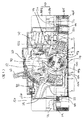
- 電源側固定接点台、電源側固定接点、電源側可動接点、可動接点台、負荷側可動接点、負荷側固定接点及び負荷側固定接点台を有し、電源側端子から開閉可能な接点部分を介して負荷側端子に至る主回路と、前記可動接点台を回動させることにより前記主回路を開閉する開閉機構部と、前記主回路の電流が異常状態となったときに前記開閉機構部を引き外すための機械的出力を発生する引外し機構部と、絶縁物により形成されて前記主回路の少なくとも前記接点部分をその内部に格納する格納手段と、絶縁物により形成されて前記主回路と前記開閉機構と前記引外し機構部と前記格納手段を格納するよう構成された筐体を備えた回路遮断器であって、
前記電源側端子と前記負荷側端子と前記引き外し機構部とが前記格納手段の外部に配設されるよう構成されたユニットを有し、
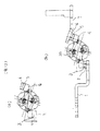
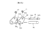
前記引き外し機構は、オイルダッシュポット、コイル、及び継鉄とより構成し、
該オイルダッシュポットの端部に該継鉄を固着し、
前記負荷側固定接点台の立上り部の上端部は前記コイルの一方の端部と固着し、
前記負荷側固定接点台の立上り部と前記負荷側端子の立上り部を前記コイルを介して接続して、
前記負荷側固定接点台と前記コイルと前記負荷側端子とを一体化し、
前記ユニットに装着することを特徴とする回路遮断器。
Priority Applications (1)
| Application Number | Priority Date | Filing Date | Title |
|---|---|---|---|
| JP2005119150A JP4215741B2 (ja) | 2005-04-18 | 2005-04-18 | 回路遮断器 |
Applications Claiming Priority (1)
| Application Number | Priority Date | Filing Date | Title |
|---|---|---|---|
| JP2005119150A JP4215741B2 (ja) | 2005-04-18 | 2005-04-18 | 回路遮断器 |
Related Parent Applications (1)
| Application Number | Title | Priority Date | Filing Date |
|---|---|---|---|
| JP22009498A Division JP3721266B2 (ja) | 1998-08-04 | 1998-08-04 | 回路遮断器 |
Publications (2)
| Publication Number | Publication Date |
|---|---|
| JP2005251757A JP2005251757A (ja) | 2005-09-15 |
| JP4215741B2 true JP4215741B2 (ja) | 2009-01-28 |
Family
ID=35031991
Family Applications (1)
| Application Number | Title | Priority Date | Filing Date |
|---|---|---|---|
| JP2005119150A Expired - Fee Related JP4215741B2 (ja) | 2005-04-18 | 2005-04-18 | 回路遮断器 |
Country Status (1)
| Country | Link |
|---|---|
| JP (1) | JP4215741B2 (ja) |
Families Citing this family (4)
| Publication number | Priority date | Publication date | Assignee | Title |
|---|---|---|---|---|
| KR101026306B1 (ko) * | 2009-10-20 | 2011-03-31 | 엘에스산전 주식회사 | 순시 트립 기구를 가진 배선용차단기 |
| KR101971230B1 (ko) * | 2017-10-30 | 2019-04-22 | 엘에스산전 주식회사 | 배선용 차단기의 샤프트 어셈블리 및 이의 조립방법 |
| US10811207B2 (en) * | 2018-07-18 | 2020-10-20 | Lsis Co., Ltd. | Arc extinguishing unit of molded case circuit breaker |
| CN110164724B (zh) * | 2019-05-27 | 2024-02-23 | 浙江正泰电器股份有限公司 | 自动转换开关电器 |
-
2005
- 2005-04-18 JP JP2005119150A patent/JP4215741B2/ja not_active Expired - Fee Related
Also Published As
| Publication number | Publication date |
|---|---|
| JP2005251757A (ja) | 2005-09-15 |
Similar Documents
| Publication | Publication Date | Title |
|---|---|---|
| JP3721266B2 (ja) | 回路遮断器 | |
| JP4012226B2 (ja) | 配線用遮断器の接触子アセンブリ | |
| US8264306B2 (en) | Movable contactor assembly for current limiting type molded case circuit breaker | |
| US8207459B2 (en) | Mold cased circuit breaker | |
| US20070194869A1 (en) | Integrated maglatch accessory | |
| JP4215741B2 (ja) | 回路遮断器 | |
| EP2980827B1 (en) | Panel board to circuit breaker positive retention interlock | |
| US9384912B2 (en) | Circuit breaker | |
| JP2013037799A (ja) | 回路遮断器 | |
| KR100676968B1 (ko) | 한류형 배선용 차단기의 접촉자 어셈블리 | |
| JP2020009767A (ja) | 回路遮断器の開閉機構 | |
| KR20090085976A (ko) | 배선용 차단기의 한류기구장치 | |
| CN101752149B (zh) | 电路断路器 | |
| US9425002B2 (en) | Circuit breaker | |
| JP2005251758A (ja) | 回路遮断器 | |
| WO2014167605A1 (ja) | 回路開閉器、および回路遮断器 | |
| US8717127B2 (en) | Circuit breaker | |
| CN209169084U (zh) | 断路器 | |
| KR200496083Y1 (ko) | 배선용 차단기의 가동자 어셈블리 | |
| CN217239371U (zh) | 分合闸机构和微型断路器 | |
| KR200396951Y1 (ko) | 회로차단기 | |
| JP2000113800A (ja) | 漏電遮断器 | |
| AU2003214137B9 (en) | Circuit breaker having double pole interruption | |
| KR200376453Y1 (ko) | 배선용 차단기의 샤프트캡 구조 | |
| KR200430940Y1 (ko) | 배선용 차단기의 로테이트 핀 보정장치 |
Legal Events
| Date | Code | Title | Description |
|---|---|---|---|
| RD02 | Notification of acceptance of power of attorney |
Free format text: JAPANESE INTERMEDIATE CODE: A7422 Effective date: 20060511 |
|
| RD04 | Notification of resignation of power of attorney |
Free format text: JAPANESE INTERMEDIATE CODE: A7424 Effective date: 20060511 |
|
| A131 | Notification of reasons for refusal |
Free format text: JAPANESE INTERMEDIATE CODE: A131 Effective date: 20071218 |
|
| A521 | Written amendment |
Free format text: JAPANESE INTERMEDIATE CODE: A523 Effective date: 20080214 |
|
| A131 | Notification of reasons for refusal |
Free format text: JAPANESE INTERMEDIATE CODE: A131 Effective date: 20080610 |
|
| A521 | Written amendment |
Free format text: JAPANESE INTERMEDIATE CODE: A523 Effective date: 20080801 |
|
| TRDD | Decision of grant or rejection written | ||
| A01 | Written decision to grant a patent or to grant a registration (utility model) |
Free format text: JAPANESE INTERMEDIATE CODE: A01 Effective date: 20081028 |
|
| A01 | Written decision to grant a patent or to grant a registration (utility model) |
Free format text: JAPANESE INTERMEDIATE CODE: A01 |
|
| A61 | First payment of annual fees (during grant procedure) |
Free format text: JAPANESE INTERMEDIATE CODE: A61 Effective date: 20081104 |
|
| R150 | Certificate of patent or registration of utility model |
Free format text: JAPANESE INTERMEDIATE CODE: R150 |
|
| FPAY | Renewal fee payment (event date is renewal date of database) |
Free format text: PAYMENT UNTIL: 20111114 Year of fee payment: 3 |
|
| LAPS | Cancellation because of no payment of annual fees |