JP4214432B2 - Double-side exposure system - Google Patents
Double-side exposure system Download PDFInfo
- Publication number
- JP4214432B2 JP4214432B2 JP34527298A JP34527298A JP4214432B2 JP 4214432 B2 JP4214432 B2 JP 4214432B2 JP 34527298 A JP34527298 A JP 34527298A JP 34527298 A JP34527298 A JP 34527298A JP 4214432 B2 JP4214432 B2 JP 4214432B2
- Authority
- JP
- Japan
- Prior art keywords
- exposure
- exposed
- mask
- plate
- double
- Prior art date
- Legal status (The legal status is an assumption and is not a legal conclusion. Google has not performed a legal analysis and makes no representation as to the accuracy of the status listed.)
- Expired - Fee Related
Links
Images


Landscapes
- Exposure And Positioning Against Photoresist Photosensitive Materials (AREA)
Description
【0001】
【発明の属する技術分野】
本発明は、両面露光装置に関する。詳しくは、プリント基板材やリードフレーム材等の被露光板の表裏両側の露光処理面を所定の露光パターンが形成された露光マスクを通して順次露光する両面露光装置、特に、露光用の光源が1つである両面露光装置に関するものである。
【0002】
【従来の技術】
例えば、高密度なプリント配線板を製造する工程で用いられる露光装置にあっては、解像度を高めるために、通常、露光用光源として超高圧な水銀灯が用いられる。
この種の水銀灯は1本50万円程度もする極めて高価なものでありながら、その性質上、連続点灯で使用することが必要で、しかも、寿命は500時間程度しかもたないので、この種の露光装置には、なるべく1個の光源を使用することと、光源の利用効率を少しでも高めることが要求される。即ち、光源の寿命が続く間にできるだけ多くの露光を済ませることによってプリント基板材1枚当たりの露光コスト(光源のランニングコスト)を可及的に抑えたいからである。
【0003】
光源の利用効率を高めるためには、プリント基板材の搬送を担う機構や露光マスクとのアライメントを担う調整機構等の各種機械的動作部の動作スピードを可及的に高めることはもとより、露光待ち等の待ち時間をゼロに近付けることが重要である。
【0004】
図13は、特願平9−343971号に記載された従来の両面露光装置の一例100を示すものである。
同図において、101はプリント基板材Pを着脱自在に保持するワーク保持ベースを示し、このワーク保持ベース101は左右両面に負圧吸着プレート103が設けられ、受入部105と取出部107との間に位置したホーム位置(一点鎖線で示す位置)と、それぞれ露光マスク113を備えた左右2つのマスク保持機構109L、109Rとの間に位置した露光位置(実線で示す位置)との間を繰返し移動される。
【0005】
111は光源としての水銀ショートアークランプを示し、このランプから発射した光の順路は図示しない光路切換え手段によって、左側のマスク保持機構109Lにその背後から照射する光路と、右側のマスク保持機構109Rにその背後から照射する光路とに切り替えられる。
受入部105は、供給されて来る未露光のプリント基板材Pを予備的位置合わせした後、ホーム位置に来ているワーク保持ベース101の左側の負圧吸着プレート103に受け取らせるように構成されている。
【0006】
そして、ホーム位置でプリント基板材Pを受け取ったワーク保持ベース101が露光位置に来ると、左側のマスク保持機構109Lがプリント基板材Pに接触するように前進して、このプリント基板材Pと当該露光マスク113とのアライメントを行った後、確定的に吸着し、ここで、一方の露光面に対する露光が実行される。
【0007】
この露光が終了すると、吸着が解除されたのち左側のマスク保持機構109Lが後退し、今露光が行われた片面露光済みのプリント基板材Pを左側の載替えハンド115Lが受取ってそれを右側の載替えハンド115Rに引渡す。このように引き渡されたプリント基板材Pは、一旦ホーム位置に戻ったワーク保持ベース101が露光位置に来たところで右側の負圧吸着プレート103に吸着保持される、即ち、乗せ替えられる。そして、右側の負圧吸着プレート103にプリント基板材Pが保持されると、右側のマスク保持機構109Rがプリント基板材Pに接触するように前進して、このプリント基板材Pと当該露光マスク113とのアライメントを行った後、確定的に吸着し、ここで、他方の露光面に対する露光が実行される。これによって両面の露光が完了する。
【0008】
この露光が済むと、吸着が解除されたのち左側のマスク保持機構109Rが後退し、ここで、ワーク保持ベース101がホーム位置に戻り、左側の負圧吸着プレート103が受入部105から未露光のプリント基板材Pを受け取ると共に、右側の吸着プレート103が保持している両面露光済みのプリント基板材Pが取出し部107によって取り外される。
【0009】
図14の(A)は、上記した両面露光装置100を具体化した一つの型式のものによる動作をタイムチャート化して示すものであり、各動作や処理に必要な時間は同図の秒単位時間スケールで示す通りである。露光に要する時間は、通常の場合、約3秒以下であり、このタイムチャートにおいては3秒に設定されていて、未露光のプリント基板材Pの受取りから始まって両面の露光が済んで次の未露光のプリント基板材Pの受取りが開始されるまでの1サイクル時間は22秒である。
この図を見て分かるように、両面露光装置100の使用に当たっての露光時間が3秒程度である場合は、左側の露光が終了して右側の露光が開始されるまでに待ち時間は殆ど無い。
【0010】
【発明が解決しようとする課題】
ところが、例えばプリント基板材Pに塗布されるレジストインキの種類によっては露光時間を長くしなければならないものがあり、この露光時間が長くなると、機械的動作部の露光準備動作が全て完了しても、一方の露光面に対する露光が終了しないうちは他方の露光面に対する露光を開始することができず、これがロスタイムになってしまうという問題がある。
【0011】
図14の(B)は、両面露光装置100を使用して、両面共に露光を8秒行う場合のタイムチャートを示すものである。この場合は、右側の露光準備が完了した時点から露光が開始されるまでに5.5秒の待ち時間が生じ、左側のプリント基板材の引渡しが済んでからワーク保持ベース101がホーム位置へ移動できるまで、即ち、右側の露光と事後処理が済むまでに5.5秒の待ち時間が生じる。この結果、1サイクルに要する時間が32秒になってしまう。これを図14の(A)と比較すると、1サイクル当たり約1.5倍の時間がかかることになるので、ランプ111のランニングコストが1.5倍近くに跳ね上がってしまう。
【0012】
本発明は上記した従来の問題点に鑑みて為されたものであり、露光時間が延びても、ロスタイムがあまり延びないようにすることができる両面露光装置を提供することを目的とする。
【0013】
【課題を解決するための手段】
この目的を達成するために、本発明の両面露光装置は、被露光板の表裏両露光面を所要の露光パターンが形成された露光マスクを通して露光する両面露光装置であって、被露光板の一方の露光面に対する露光に用いる露光マスクが取り付けられる第一のマスク保持機構と、この第一のマスク保持機構に対向した露光位置と未露光の被露光板を受け取るホーム位置との間を移動する第一のワーク保持ベースとを有した第一の処理部と、第一のマスク保持機構と互いに対向する位置関係で配置され、被露光板の他方の露光面に対する露光に用いる露光マスクが取り付けられる第二のマスク保持機構と、この第二のマスク保持機構に対向した露光位置と両面露光済みの被露光板を取り外されるホーム位置との間を移動する第二のワーク保持ベースとを有した第二の処理部と、前記露光位置の第一のワーク保持ベースから一方の露光面が露光された被露光板を受け取り、その被露光板を第一のワーク保持ベースがホーム位置に移動しているときにマスク保持機構の対向方向に移動して、前記露光位置の第二のワーク保持ベースに他方の露光面を露光し得る向きで乗せ替えるようにしたワーク乗替え手段と、1つの光源と、この光源からの光の光路を第一の処理部に向かう光路と第二の処理部に向かう光路に選択的に切り替える光学系とを備えたものである。
【0014】
即ち、本発明は、被露光板を保持して露光マスクに対向させるためのワーク保持ベースを、被露光板の一方の露光面に対する露光に専用のものと、他方の露光面に対する露光に専用のものと2つ設けたものである。このようにすれば、未露光の被露光板の受取りや移送と露光及びその事前処理等の動作位相と、片面露光済みの被露光板の移送や露光及びその事前処理等の動作位相とをずらせることができる。
【0015】
従って、第一の処理部による露光以外の動作が行われている間に第二の処理部による露光が行われるように、第一の処理部と第二の処理部の動作位相をずらせることによって、光源が1つでも、露光待ちのロスタイムが生じるのを確実に防止できる。また、この動作位相のズレに加えて、第一の処理部での露光終了後、第二のワーク保持ベースが露光位置に来る前にワーク乗替え手段が片面露光済みの被露光板を第二のワーク保持ベースに保持させることができる状態になるように、各部の動作タイミングを組むことにより、露光待ちのロスタイムだけで無く、ワーク保持ベースの移動待ちのロスタイムが生じることについても防止できる。また、第一のマスク保持機構と第二のマスク保持機構とを互いに対向する位置関係で配置し、ワーク乗替え手段によって、露光位置の第一のワーク保持ベースから一方の露光面が露光された被露光板を受け取り、その被露光板を第一のワーク保持ベースがホーム位置に移動しているときにマスク保持機構の対向方向に移動して、露光位置の第二のワーク保持ベースに他方の露光面を露光し得る向きで乗せ替えるようにしたものである。このようにすると、被露光板の乗替えに必要な特別なスペースは殆ど必要無いので、その分、装置を小型化することができる。
【0016】
請求項2の発明は、請求項1に記載した両面露光装置において、ワーク保持ベースによる被露光板の保持が、少なくとも両面の露光が終了するまで、被露光板を垂直な姿勢にして行われるようにしたものである。
このようにすれば、露光マスクと被露光板をいずれも立てた姿勢で露光が行われるので、塵埃の付着による露光不良の発生をかなり防止することができる。
【0017】
請求項3の発明は、請求項1または2に記載した両面露光装置において、第一のマスク保持機構と第二のマスク保持機構とが左右に互いに対向して配置され、ワーク乗替え手段が、露光位置の左側の第一のワーク保持ベースから一方の露光面が露光された被露光板を受け取って保持する左側の乗替えハンドと、左側の乗替えハンドが保持している被露光板に右側から対向して左側の乗替えハンドから被露光板を受け取り、露光位置の右側の第二のワーク保持ベースに受け渡す右側の乗替えハンドを有するものである。このようにすると、左側の乗替えハンドで第一のワーク保持ベースから一方の露光面が露光された被露光板を受け取り、その被露光板を右側の乗替えハンドで受け取って右側の第二のワーク保持ベースに他方の露光面を露光し得る向きで乗せ替えることができる。
【0018】
【発明の実施の形態】
以下に、本発明の実施の形態に係るプリント基板材両面露光装置1を図面に従って説明する。(構造については、図1から図3を参照)
3はプリント基板材両面露光装置1の外筐を示す。この外筐3の内部の前後方向(図1に向かって手前側を前方とし、同図における左側を左方とする。)における略中間の位置に垂直な壁状をした機構ベース5が設けられ、この機構ベース5の後側空間は主として光学系配置室7になっている。また、機構ベース5から前側の空間における高さ方向中間部には水平な仕切り板9が配置されていて、この仕切り板9の下側が受入/取出室11になっており、上側が露光室13になっている。仕切り板9の左右方向における中間部には受入/取出室11と露光室13との通路になる通路口9aが設けられている。
外筐3の左側壁にはワーク入口15が形成され、右側壁にはワーク出口17が形成されている。
【0019】
外筐3内には通路口9aを通って上下方向へ移動する左右2つのワーク保持エレベータ21Lと21Rが設けられ、露光室13のうちワーク保持エレベータ21L、21Rの移動軌跡の左右両脇にマスク保持機構23L、23Rが設けられている。
左側のワーク保持エレベータ21Lとマスク保持機構23Lとによって第一の処理部25Lが構成され、右側のワーク保持エレベータ21Rとマスク保持機構23Rとによって第二の処理部25Rが構成される。この第一の処理部25Lは主としてプリント基板材Pの一方の露光面に対する露光を担う部分であり、第二の処理部25Rは主としてプリント基板材Pの他方の露光面に対する露光を担う部分である。
【0020】
受入/取出室11のうちワーク保持エレベータ21Lの移動軌跡の左側にはローダー機構27が設けられ、このローダー機構27の左側に受入コンベア29が配置されている。
受入コンベア29の左端はワーク入口15に臨んでいて、外筐3に対して左方から延びてきている図示しない供給コンベアに載って移送されて来たプリント基板材はPワーク入口15を通って受入コンベア29に乗る。このプリント基板材Pは、その表裏両面に紫外線硬化型レジスト膜が形成された状態で供給されて来る。そして、受入コンベア29上に載ったプリント基板材Pは受入れコンベア29が有する図示しない駆動ローラーによってローダー機構27の上面に移される。
【0021】
ローダー機構27は、この上面に移されたプリント基板材Pを負圧手段によって吸着保持する機能と、そのプリント基板材Pの先端側エッジの位置をプリアライメントセンサー31(図1参照)と協働して調整するプリアライメント機能とを備えており、このプリアライメントが終了した後、図1に二点鎖線で示すように90°回転してその上面を右側に向けた横倒姿勢となって水平に移動する。このような動作を行うために、ローダー機構27は、機構ベース5から前方へ突出するように延びた回転軸33に支持されており、この回転軸33は、機構ベース5の後側で左右方向へ移動自在なるように設けられた図示しない移動手段に支持されている。
【0022】
右側のワーク保持エレベータ21Rの移動軌跡の右側にはアンローダー機構35が設けられ、このアンローダー機構35の右側に取出コンベア37が設けられている。
アンローダー機構35は、その上面が図示しない負圧手段によって随時負圧状態にされると共に、図1に実線で示す水平姿勢と、90°回動してその上面を左側へ向けた横倒姿勢とに姿勢変更され、この横倒姿勢で水平移動する。このような動作を行うために、アンローダー機構35も、機構ベース5から前方へ突出するように延びた回転軸33´に支持されており、この回転軸33´は、機構ベース5の後側で左右方向へ移動自在なるように設けられた図示しない移動手段に支持されている。
【0023】
取出コンベア37の右端は、前記ワーク出口17に臨んでいる。アンローダー機構35は、右側のワーク保持エレベータ21Rがプリント基板材Pを保持してホーム位置に降りて来たとき、横倒姿勢でそのプリント基板材Pを取り外した後水平な姿勢に戻る。そして、アンローダー機構35が取り外したプリント基板材Pは、このアンローダー機構35が有する図示しない駆動ローラーによって取出コンベア37に移され、ここから、ワーク出口17を通って図示しない搬送コンベアに乗って次の工程、例えば、現像工程へ搬送されて行く。
【0024】
機構ベース5の背面の左右方向における中央には、上下方向へ互いに平行に延びる左右それぞれ2本ひと組の垂直ガイドレール36が固定されており、この左右の垂直ガイドレール36にそれぞれスライドベース39が摺動自在に支持されている。
これらスライドベース39からは水平なアーム41が、それぞれ前方へ向けて突出されている。このアーム41は機構ベース5に形成された縦長の長孔5aを通して前方へ突出し、このアーム41の前端にワーク保持エレベータ21L、21Rが各別に固定されている。
【0025】
ワーク保持エレベータ21L、21Rは、プリント基板材Pを垂直姿勢で吸着保持して上下方向へ移動するものである。図面では、これらワーク保持エレベータ21L、21Rを矩形の単なる平板形状だけで示してあるが、実際には、垂直な壁状をした移動ベースと、この移動ベースの一方の面(左側のワーク保持エレベータ21Lでは左側面、右側のワーク保持エレベータ21Rでは右側面)に設けられた多数の吸気孔を備えた負圧吸着プレートと、この負圧吸着プレートに接続された吸気系等から構成されており、その負圧吸着プレートにプリント基板材Pが着脱自在に吸着保持される構造になっている。
【0026】
スライドベース39は図示しないサーボモーターによって回転されるボールネジによって移動され、この移動によりワーク保持エレベータ21L、21Rが仕切り板9の通路口9aを通って上昇又は下降する。これらワーク保持エレベータ21L、21Rの移動は、図1に実線で示すようにローダー機構27とアンローダー機構35との間に入ったホーム位置と、同図に二点鎖線で示すように左右のマスク保持機構23Lと23Rとの間に入った露光位置との間で行われる。
【0027】
機構ベース5の背面における垂直ガイドレール36の左右両脇には左右方向へ延びる水平ガイドレール45(図2参照)が固定され、これら水平ガイドレール45にそれぞれスライドベース47が摺動自在に支持されている。
この左右のスライドベース47からはそれぞれアーム49が前方へ向けて水平に突出されている。このアーム49は機構ベース5に形成された孔5bを通して前方へ突出し、左側のアーム49の前端には左側のマスク保持機構23Lが固定され、右側のアーム49の前端には右側のマスク保持機構23Rが固定されている。
【0028】
スライドベース47は図示しないボールナットを有し、そのボールナットにはサーボモータ51によって回転されるボールスクリュー53が螺合されている。従って、ボールスクリュー53が回転することによってスライドベース47が左右方向へ移動され、これと一体的にマスク保持機構23L、23Rが左右方向へ移動する。このマスク保持機構23L、23Rの移動は、ワーク保持エレベータ21L、21Rの移動軌跡からある程度離間した後退位置と、ワーク保持エレベータ21L、21Rに保持されたプリント基板材に接触した前進位置との間で行われる。
【0029】
図面では、マスク保持機構23L、23Rを矩形の枠形だけで示してあるが、実際には、この形のベースと、このベースの一方の面(左側のマスク保持機構23Lでは右側面、右側のマスク保持機構23Rでは左側面)に設けられたアライメントユニットと、このアライメントユニットに保持された露光マスク55(図3では梨地模様を付けてある)と、整合誤差検出用のカメラ等を備えた構造になっていて、アライメントユニットが駆動することにより、露光マスク55が垂直面内において微細に位置調節される。
【0030】
露光マスク55には所定の透光パターンが設けられると共に、所定の位置に図示しないフォトマスクマークが設けられており、カメラがこのフォトマスクマークとプリント基板材の基準孔とを重ねて見ることで誤差を検出し、その誤差に応じた修正をアライメントユニットが行うことで、露光マスク55とプリント基板材とを相対的にアライメントする。
【0031】
外筐3の前記光学系配置室7における中央下部には、1つのランプ61が配置されている。このランプ61には水銀ショートアークランプが用いられ、光を真上に向かって照射する向きで設けられている。
ランプ61の上方にはハーフミラー型の回転ミラー63が設けられている。この回転ミラー63は、図1に破線で示すようにランプ61からの光を左方へ向けて水平に反射する第一の位置と、同図に二点鎖線で示すようにランプ61からの光を右方へ向けて水平に反射する第二の位置と、水平な姿勢となったニュートラル位置との間で姿勢を制御される。
【0032】
左側のマスク保持機構23Lの左背後には照射ミラー65Lが配置され、右側のマスク保持機構23Rの右背後には照射ミラー65Rが配置されている。そして、光学系配置室7の左右両端には反射ミラー67が配置されると共に、これら反射ミラー67と回転ミラー63との間にそれぞれフライアイレンズ69が介挿されている。
従って、ランプ61からの光は、回転ミラー63が第一の位置に来ている状態では、左側の反射ミラー67と左側の照射ミラー65Lを経て左側のマスク保持機構23Lが有する露光マスク55に照射するように光路を制御され、また、回転ミラー63が第二の位置に来ている状態では、右側の反射ミラー67と右側の照射ミラー65Rを経て右側のマスク保持機構23Rが有する露光マスク55に照射するように光路を制御される。
【0033】
しかして、プリント基板材Pを保持した左側のワーク保持エレベータ21Lが露光位置に来ている状態で回転ミラー63が第一の位置へと回動すると、ランプ61からの光は左側の露光マスク55を通して当該プリント基板材Pに照射され、それによって、当該プリント基板材Pの一方の露光面が左側の露光マスク55の露光パターンによって露光される。
また、露光位置に来ている右側のワーク保持エレベータ21Rにプリント基板材Pが保持された状態で回転ミラー63が第二の位置へと移動すると、ランプ61からの光は右側の露光マスク55を通して当該プリント基板材Pに照射され、それによって、当該プリント基板材Pの他方の露光面が右側の露光マスク55の露光パターンによって露光される。
この露光は、露光マスク55がプリント基板材Pに密着した状態で行われる。
【0034】
機構ベース5の上には天井ベース71が配置され、この天井ベース71の上面に左右方向へ延びるガイドレール73が固定されている。
75L、75Rは乗替え機構を示し、この乗替え機構75L、75Rは乗替えハンド77L、77Rを有する。79は乗替え機構75L、75Rのスライドベースを示し(図3参照)、前後に長い水平な板状を為し、その後端部がガイドレール73に摺動自在に支持されている。左側のスライドベース79はエアーシリンダ81によって左右方向へ比較的短い距離移動され、右側のスライドベース79はサーボモータ83で回転されるボールネジ85によって左右方向へ比較的長い距離移動される。
【0035】
スライドベース79の前端部にはそれぞれ乗替えハンド駆動部87が取り付けられている。この乗替えハンド駆動部87は平行リンク89を有し、この平行リンク89の回動先端に乗替えハンド77L、77Rが取り付けられている。
乗替えハンド77L、77Rは中空構造になっていて、その互いに対向した側面に多数の吸着突部が設けられている。そして、乗替えハンド77L、77Rの内部空間には図示しない吸気手段が接続されており、内部空間が負圧になると、吸着突部の先端面に負圧吸引力が働く。
【0036】
平行リンク89は、乗替えハンド駆動部87から前方へ水平に延びた姿勢と真下へ延びた姿勢とにほぼ90°角度姿勢を変更される。
従って、乗替えハンド77L、77Rは平行リンク89が回動することによって、水平な姿勢のまま上下方向へ移動され、この方向への移動は、図3に示すようにマスク保持機構23L、23Rより高い待機位置と、図1に示すようにマスク保持機構23L、23Rの中央部より稍高い下降位置との間で行われる。
プリント基板材両面露光装置1は以上のように構成されている。
【0037】
次に、プリント基板材両面露光装置1の動作を説明する(図4から図12参照)。図12はこの装置1による動作のタイムチャートを示すものであるが、運転開始当初は第一の処理部25Lのみが働いて、この第一の処理部25Lによる一回目の露光処理が完了するまでは同図の※印を付けた動作は行われない。同図の縦の破線どうしの間隔は1秒間を示す。
【0038】
初期状態において、ワーク保持エレベータ21L、21Rはホーム位置に来ており、マスク保持機構23L、23Rは後退位置で待機し、ローダー機構27とアンローダー機構35は上向きの姿勢で待機し、乗替えハンド77L、77Rは待機位置に来ている。
また、回転ミラー63はニュートラル位置に保持され、運転開始と同時にランプ61が点灯される。この点灯を途中で絶つことはされず、運転完了までランプ61はつけっ放しになる。
【0039】
この状態からプリント基板材Pが受入コンベア29に乗載すると、そのプリント基板材Pは、前記したように、ローダー機構27に移されてプリアライメントされ、次いで、ローダー機構27が横倒姿勢となって右移動する(図4参照)。これにより、ローダー機構27が保持しているプリント基板材Pをワーク保持エレベータ21Lに吸着保持させる(図12の「受取り」)。
このようにしてプリント基板材Pを保持した左側のワーク保持エレベータ21Lは、図4に二点鎖線で示すように露光位置へと上昇する(図12の「上昇」)。そして、ローダー機構27は、元の位置に戻って次のプリント基板材Pについての処理を実行した後、左側のワーク保持エレベータ21Lがホーム位置に降りて来るのを待つ。
【0040】
左側のワーク保持エレベータ21Lが露光位置に来ると、これが保持しているプリント基板材Pの一方の露光面が左側のマスク保持機構23Lと対向する。
ここで、このマスク保持機構23Lが前進位置へと移動して(図12の「前進」)、その露光マスク55が当該プリント基板材Pにソフトコンタクトして前記アライメントを行い(図12の「アライメント」)、これが済むと、当該マスク55とプリント基板材Pとが密着し合う(図12の「吸着」)。ここで、回転ミラー63が第一の位置へと回動され(図12の「第一の位置」)、これにより、ランプ61からの紫外光がマスク保持機構23Lの露光マスク55を通してプリント基板材Pの一方の露光面に照射されて当該露光面に対する露光が実行される(図12の「露光」)。この状態が図5に示す状態である。
【0041】
この露光に必要な時間(8秒)が経過すると、回転ミラー63がニュートラル位置に戻されると共に、吸着が解除(図12の「吸着解除」)されたのち左側のマスク保持機構23Lが後退位置へと戻される(図12の「後退」)。
次いで、左側の乗替えハンド77Lが、図6に示すように、下降位置を経て右側へ移動されてプリント基板材Pに吸着し、これを保持して下降位置まで後退する(図12の「引渡し」)。即ち、一方の露光面に対する露光が済んだプリント基板材Pが左側のワーク保持エレベータ21Lから左側の乗替えハンド77Lに引き渡される。この引渡しが済むと、左側のワーク保持エレベータ21Lは同図に二点鎖線で示すようにホーム位置へと降りて行く(図12の「下降」)。
【0042】
左側のワーク保持エレベータ21Lがホーム位置に降りてくると、ローダー機構27から次のプリント基板材Pを受け取る。
一方、左側のワーク保持エレベータ21Lがホーム位置に降りると、図7に示すように、右側の乗替えハンド77Rが待機位置の高さを保ったまま左方へ移動されたのち下降位置へと下がって左側の乗替えハンド77Lが保持しているプリント基板材Pに右側から対向し、ここで、左側の乗替えハンド77Lが右方へ移動して当該プリント基板材Pを右側の乗替えハンド77Rに受け渡たす(図12の「受渡し」)。このようにしてプリント基板材P11を受け渡された右側の乗替えハンド77Rは、同図に二点鎖線で示すように、左右のワーク保持エレベータ21L、21Rの各移動軌跡の間まで水平移動してその位置に待機する(図12の「受取り後 待機」)。
【0043】
次いで、第一の処理部25Lによる前記「上昇」、「前進」、「アライメント」、「露光」の各動作が同様に繰り返され、この動作の中の「アライメント」が開始された直後(このタイミングは、二回目以降のサイクルにおいて、右側のワーク保持エレベータ21Rが露光位置からホーム位置へと移動したタイミングと同じタイミングである。)に、右側の乗替えハンド77Rが右側のワーク保持エレベータ21Rとマスク保持機構23Rとの間の位置へと移動する(図12の「右端へ」)。ここで、右側のワーク保持エレベータ21Rが露光位置へと上がる(図12の「上昇」)。
次いで、右側の乗替えハンド77Rが左方へ移動して当該プリント基板材P(片面露光が済んでいるプリント基板材P)を右側のワーク保持エレベータ21Rに吸着保持させる(図12の「貼付け」)。この状態が図8に示す状態であり、右側のワーク保持エレベータ21Rに吸着保持されたプリント基板材Pは、その他方の露光面が右側を向く。即ち、ワーク保持エレベータに保持される面でみれば、プリント基板材Pは乗せ替えられる間に裏返しされる。
この後、右側の乗替えハンド77Rは待機位置に戻される。
【0044】
そして、第一の処理部25Lによって露光動作が行われている間に、第二の処理部25Rにおいては、右側のマスク保持機構23Rが前進位置へと移動して(図12の「前進」)、その露光マスク55が当該プリント基板材Pの他方の露光面にソフトコンタクトし、前記アライメントが行われる(図12の「アライメント」)。
このアライメントが終わる直前に、第一の処理部25Lにおいては「露光」が終了し、次いで、回転ミラー63が一旦ニュートラル位置に戻される。
【0045】
そして、第二の処理部25Rにおいては、上記「アライメント」が終わると右側のマスク保持機構23Rの露光マスク55とプリント基板材Pとが密着し合う(図12の「吸着」)。ここで、回転ミラー63が第二の位置へと回動され(図12の「第二の位置」)、これにより、ランプ61からの紫外光がマスク保持機構23Rの露光マスク55を通してプリント基板材Pの他方の露光面に照射されて当該露光面に対する露光が実行される(図12の「露光」)。この状態が図9に示す状態であり、第一の処理部25Lにおいては、片面露光済みのプリント基板材Pがワーク保持エレベータ21Lから乗替えハンド77Lに引き渡され、次いで、ワーク保持エレベータ21Lはホーム位置に降りて次のプリント基板材Pを受け取りに行く。
【0046】
第二の処理部25Rにおいて露光が行われている間に、右側の乗替えハンド77Rが前記した経路を移動して片面露光済みのプリント基板材Pを右側の乗替えハンド77Rから受け取る。この状態が図10である。
次いで、第一の処理部25Lにおいてはワーク保持エレベータ21Lの「上昇」、マスク保持機構23Lの「前進」と「アライメント」が進行して行き、第二の処理部25Lにおいては、露光が終了してマスク保持機構23Rが「後退」し、ワーク保持エレベータ21Rがホーム位置に降りて、アンローダー機構35が両面露光済みのプリント基板材Pをワーク保持エレベータ21Rから取り外す。この状態が図11である。
【0047】
取り外されたプリント基板材Pは取出コンベア37を経て外筐3外へ移送される。
この後は、図8と同じ状態に移行し、以下、図9、図10、図11の状態がこの順で繰り返される。
【0048】
以上の動作の推移を図12のタイムチャートで見ると、動作や処理を何もしていない待ち時間というものは全く存在せず、1サイクル時間は26.5秒である。この時間は、露光所要時間を同じ8秒とした場合の前記従来の装置100による1サイクル時間(図14の(B))32秒と比較して、ほぼ17パーセントの時間短縮になっている。換言すれば、露光時間としては片面3秒が5秒延びて両面分で10秒延びたにも拘らず、両面分で4.5秒の延び(図14の(A)におけるロスタイム0.5秒は吸収される)に抑えることができる。
【0049】
以上、本発明の実施の形態について詳述してきたが、具体的な構成はこの実施の形態に限られるものではなく、本発明の要旨を逸脱しない範囲における設計の変更などがあっても本発明に含まれる。
例えば、実施の形態においては、本発明をプリント基板材のレジスト膜を露光するための両面露光装置に適用したが、本発明は、所定の露光パターンが形成された露光マスクを通しての露光を行うことを要する各種の被露光板の両面露光を行う両面露光装置として広く適用することができる。
【0050】
また、実施の形態においては、ワーク保持ベースが上下方向へ移動するタイプのものを示したが、本発明は、ワーク保持ベースが水平方向へ移動するタイプのものにも適用することができることは勿論である。
【0051】
【発明の効果】
以上のように、本発明に係る両面露光装置にあっては、未露光の被露光板の受取りや移送と露光及びその事前処理等の動作位相と、片面露光済みの被露光板の移送や露光及びその事前処理等の動作位相とをずらせることができるので、第一の処理部による露光以外の動作が行われている間に第二の処理部による露光が行われるように、第一の処理部と第二の処理部の動作位相をずらせることによって、光源が1つでも露光待ちのロスタイムが生じるのを確実に防止できる。また、第一のマスク保持機構と第二のマスク保持機構とを互いに対向する位置関係で配置し、ワーク乗替え手段によって、露光位置の第一のワーク保持ベースから一方の露光面が露光された被露光板を受け取り、その被露光板を第一のワーク保持ベースがホーム位置に移動しているときにマスク保持機構の対向方向に移動して、露光位置の第二のワーク保持ベースに他方の露光面を露光し得る向きで乗せ替えるようにしたので、被露光板の乗替えに必要な特別なスペースは殆ど必要無くなり、その分、装置を小型化することができる。また、第一の処理部での露光終了後、第二のワーク保持ベースが露光位置に来る前にワーク乗替え手段が片面露光済みの被露光板を第二のワーク保持ベースに保持させることができる状態になるように、各部の動作タイミングを組むことにより、露光待ちのロスタイムだけで無く、ワーク保持ベースの移動待ちのロスタイムが生じることについても防止できる。
【0052】
請求項2の発明によれば、露光マスクと被露光板をいずれも立てた姿勢で露光が行われるので、塵埃の付着による露光不良の発生をかなり防止することができる。
【0053】
請求項3の発明によれば、第一のマスク保持機構と第二のマスク保持機構とが左右に互いに対向して配置され、ワーク乗替え手段が、露光位置の左側の第一のワーク保持ベースから一方の露光面が露光された被露光板を受け取って保持する左側の乗替えハンドと、左側の乗替えハンドが保持している被露光板に右側から対向して左側の乗替えハンドから被露光板を受け取り、露光位置の右側の第二のワーク保持ベースに受け渡す右側の乗替えハンドを有するので、左側の乗替えハンドで第一のワーク保持ベースから一方の露光面が露光された被露光板を受け取り、その被露光板を右側の乗替えハンドで受け取って右側の第二のワーク保持ベースに他方の露光面を露光し得る向きで乗せ替えることができる。
【図面の簡単な説明】
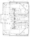
【図1】本発明の実施の形態に係るプリント基板材両面露光装置を、外筐を切断して示す正面図である。
【図2】図1に示すプリント基板材両面露光装置を外筐を切断して示す要部平面図である。
【図3】図1に示すプリント基板材両面露光装置の要部斜視図である。
【図4】図1に示すプリント基板材両面露光装置において、左側のワークエレベータによる未露光のプリント基板材の受取りが行われている状態を示す概略正面図である。
【図5】図1に示すプリント基板材両面露光装置において、第一の処理部よる露光が行われている状態を示す概略正面図である。
【図6】図1に示すプリント基板材両面露光装置において、左側の乗替えハンドがプリント基板材を受け取っている状態を示す概略正面図である。
【図7】図1に示すプリント基板材両面露光装置において、左右の乗替えハンドがプリント基板材の受け渡しを行っている状態を示す概略正面図である。
【図8】図1に示すプリント基板材両面露光装置において、第一の処理部による露光と右側のワークエレベータへのプリント基板材の貼り付けが行われている状態を示す概略正面図である。
【図9】図1に示すプリント基板材両面露光装置において、左側の乗替えハンドによるプリント基板材の受取りと第二の処理部による露光が行われている状態を示す概略正面図である。
【図10】図1に示すプリント基板材両面露光装置において、第二の処理部による露光が行われている間に左右の乗替えハンドがプリント基板材の受け渡しを行っている状態を示す概略正面図である。
【図11】図1に示すプリント基板材両面露光装置において、第一の処理部よる露光と両面露光済みのプリント基板材の取外しが行われている状態を示す概略正面図である。
【図12】図1に示すプリント基板材両面露光装置による動作のタイムチャート図である。
【図13】従来の両面露光装置の一例を示す概略図である。
【図14】図13に示す両面露光装置による動作のタイムチャートを、露光時間の異なる(A)、(B)2例示す図である。
【符号の説明】
1 両面露光装置
21L 第一のワーク保持ベース
21R 第二のワーク保持ベース
23L 第一のマスク保持機構
23R 第二のマスク保持機構
25L 第一の処理部
25R 第二の処理部
55 露光マスク
61 光源
63、65L、65R、67、69 光学系
75L、75R ワーク乗替え手段
P 被露光板[0001]
BACKGROUND OF THE INVENTION
The present invention relates to a double-side exposure apparatus. Specifically, a double-sided exposure apparatus that sequentially exposes exposure processing surfaces on both the front and back sides of an exposed plate such as a printed circuit board material or a lead frame material through an exposure mask on which a predetermined exposure pattern is formed. It is related with the double-sided exposure apparatus which is.
[0002]
[Prior art]
For example, in an exposure apparatus used in a process for manufacturing a high-density printed wiring board, an ultra-high pressure mercury lamp is usually used as an exposure light source in order to increase resolution.
Although this kind of mercury lamp is extremely expensive, costing about 500,000 yen, it is necessary to use it by continuous lighting due to its nature, and the lifetime is only about 500 hours. The exposure apparatus is required to use one light source as much as possible and to improve the utilization efficiency of the light source as much as possible. That is, the exposure cost per one printed circuit board material (running cost of the light source) is to be suppressed as much as possible by performing as many exposures as possible while the lifetime of the light source continues.
[0003]
In order to increase the light source usage efficiency, not only increase the operating speed of various mechanical operating units such as the mechanism that transports printed circuit board materials and the adjustment mechanism that aligns with the exposure mask, It is important to make the waiting time close to zero.
[0004]
FIG. 13 shows an example 100 of a conventional double-side exposure apparatus described in Japanese Patent Application No. 9-343971.
In the figure,
[0005]
The
[0006]
When the
[0007]
When this exposure is completed, the left-side
[0008]
After the exposure is completed, the suction is released and then the left
[0009]
FIG. 14A is a time chart showing the operation of one type embodying the double-sided
As can be seen from this figure, when the exposure time for using the double-sided
[0010]
[Problems to be solved by the invention]
However, for example, depending on the type of resist ink applied to the printed circuit board material P, there are cases where the exposure time must be extended. If this exposure time is increased, even if all the exposure preparation operations of the mechanical operation unit are completed. As long as the exposure on one exposure surface is not completed, the exposure on the other exposure surface cannot be started, which results in a loss time.
[0011]
FIG. 14B shows a time chart when the double-sided
[0012]
The present invention has been made in view of the above-described conventional problems, and an object of the present invention is to provide a double-sided exposure apparatus that can prevent the loss time from extending much even if the exposure time is extended.
[0013]
[Means for Solving the Problems]
To achieve this object, the present inventionofThe double-sided exposure apparatus is a double-sided exposure apparatus that exposes both the front and back exposure surfaces of an exposed plate through an exposure mask on which a required exposure pattern is formed. And a first work holding base that moves between an exposure position facing the first mask holding mechanism and a home position for receiving an unexposed plate to be exposed. A processing unit ofArranged in a positional relationship facing the first mask holding mechanismA second mask holding mechanism to which an exposure mask used for exposure to the other exposure surface of the plate to be exposed is attached, an exposure position facing the second mask holding mechanism, and a home from which the double-side exposed plate to be exposed is removed A second processing unit having a second workpiece holding base that moves between positions;The exposure plate having one exposed surface exposed from the first workpiece holding base at the exposure position is received, and when the first workpiece holding base is moved to the home position, the mask holding mechanism Move in the opposite direction, and change the orientation so that the other exposure surface can be exposed to the second work holding base at the exposure position.A workpiece transfer means, one light source, and an optical system that selectively switches the optical path of light from the light source to an optical path toward the first processing unit and an optical path toward the second processing unit. .
[0014]
That is, according to the present invention, the work holding base for holding the exposed plate and facing the exposure mask is dedicated to exposure on one exposure surface of the exposed plate and dedicated to exposure on the other exposure surface. Two things are provided. In this way, the operation phase of receiving, transferring, exposing, and pre-processing the unexposed exposed plate is shifted from the operation phase of transferring, exposing, and pre-processing the exposed single-side exposed plate. Can.
[0015]
Therefore, the operation phases of the first processing unit and the second processing unit are shifted so that the exposure by the second processing unit is performed while the operation other than the exposure by the first processing unit is performed. Thus, even if there is only one light source, it is possible to reliably prevent a loss time waiting for exposure to occur. Also this behaviorphaseAfter the exposure in the first processing unit is completed, the workpiece transfer means uses the exposed plate subjected to single-side exposure as the second workpiece holding base before the second workpiece holding base reaches the exposure position. By setting the operation timing of each unit so that the workpiece can be held, not only the exposure waiting loss time but also the workpiece holding base movement waiting time can be prevented.Also, the first mask holding mechanism and the second mask holding mechanism are arranged in a positional relationship facing each other, and one exposure surface is exposed from the first work holding base at the exposure position by the work transfer means. The exposure plate is received, and when the first workpiece holding base is moved to the home position, the exposure plate is moved in the opposite direction of the mask holding mechanism, and the other workpiece holding base is moved to the exposure position. In this case, the exposure surface is changed in a direction that allows exposure. In this way, since there is almost no special space necessary for changing the exposed plate, the apparatus can be reduced in size accordingly.
[0016]
According to a second aspect of the present invention, in the double-sided exposure apparatus according to the first aspect, the exposure plate is held in a vertical posture until the exposure plate is held by the work holding base at least until the exposure of both sides is completed. It is a thing.
In this way, since the exposure is performed with both the exposure mask and the exposed plate standing, the occurrence of exposure failure due to the adhesion of dust can be considerably prevented.
[0017]
The invention of
[0018]
DETAILED DESCRIPTION OF THE INVENTION
Hereinafter, a printed circuit board material double-
A
[0019]
In the
The left
[0020]
A
The left end of the receiving
[0021]
The
[0022]
An
The upper surface of the
[0023]
The right end of the take-out
[0024]
A pair of left and right
From these
[0025]
The
[0026]
The
[0027]
Horizontal guide rails 45 (see FIG. 2) extending in the left-right direction are fixed to the left and right sides of the
From each of the left and right slide bases 47,
[0028]
The slide base 47 has a ball nut (not shown), and a
[0029]
In the drawing, the
[0030]
The
[0031]
One
A half mirror
[0032]
An
Therefore, the light from the
[0033]
Thus, when the
When the
This exposure is performed with the
[0034]
A
75L and 75R indicate transfer mechanisms, and the
[0035]
A transfer
The transfer hands 77L and 77R have a hollow structure, and a plurality of suction protrusions are provided on the side surfaces facing each other. An intake means (not shown) is connected to the internal spaces of the transfer hands 77L and 77R. When the internal space becomes negative pressure, a negative pressure suction force acts on the tip surface of the suction projection.
[0036]
The
Accordingly, the transfer hands 77L and 77R are moved in the vertical direction while the
The printed board material double-
[0037]
Next, the operation of the printed board material double-
[0038]
In the initial state, the
The rotating
[0039]
When the printed circuit board material P is placed on the receiving
The left
[0040]
When the left
Here, the
[0041]
When the time necessary for this exposure (8 seconds) elapses, the rotating
Next, as shown in FIG. 6, the
[0042]
When the left
On the other hand, when the left
[0043]
Next, the “up”, “forward”, “alignment”, and “exposure” operations by the
Next, the
Thereafter, the
[0044]
Then, while the exposure operation is performed by the
Immediately before the end of the alignment, the “exposure” is completed in the
[0045]
Then, in the second processing unit 25R, when the “alignment” is completed, the
[0046]
While exposure is being performed in the second processing unit 25R, the
Next, in the
[0047]
The removed printed circuit board material P is transferred to the outside of the
Thereafter, the state shifts to the same state as in FIG. 8, and the states of FIGS. 9, 10, and 11 are repeated in this order.
[0048]
Looking at the transition of the above operation in the time chart of FIG. 12, there is no waiting time during which no operation or processing is performed, and one cycle time is 26.5 seconds. This time is approximately 17% shorter than the one cycle time (FIG. 14B) 32 seconds by the
[0049]
The embodiment of the present invention has been described in detail above, but the specific configuration is not limited to this embodiment, and the present invention can be changed even if there is a design change without departing from the gist of the present invention. include.
For example, in the embodiment, the present invention is applied to a double-sided exposure apparatus for exposing a resist film of a printed circuit board material. However, the present invention performs exposure through an exposure mask on which a predetermined exposure pattern is formed. Therefore, the present invention can be widely applied as a double-sided exposure apparatus that performs double-sided exposure of various types of exposed plates.
[0050]
In the embodiment, the type in which the workpiece holding base moves in the vertical direction is shown. However, the present invention can also be applied to a type in which the workpiece holding base moves in the horizontal direction. It is.
[0051]
【The invention's effect】
As described above, in the double-sided exposure apparatus according to the present invention, operations such as receiving, transferring and exposing an unexposed plate, and pre-processing thereofphaseAnd operations such as transferring, exposing and pre-treating exposed plates that have been exposed on one sidephaseSince the exposure by the second processing unit is performed while the operation other than the exposure by the first processing unit is performed, the first processing unit and the second processing unit By shifting the operation phase, it is possible to reliably prevent a loss time waiting for exposure to occur even with one light source.Also, the first mask holding mechanism and the second mask holding mechanism are arranged in a positional relationship facing each other, and one exposure surface is exposed from the first work holding base at the exposure position by the work transfer means. The exposure plate is received, and when the first workpiece holding base is moved to the home position, the exposure plate is moved in the opposite direction of the mask holding mechanism, and the other workpiece holding base is moved to the exposure position. Since the exposure surface is changed in a direction in which exposure can be performed, a special space necessary for changing the exposed plate is almost unnecessary, and the apparatus can be miniaturized correspondingly. In addition, after the exposure in the first processing unit is completed, the workpiece transfer means may hold the exposed plate subjected to single-side exposure on the second workpiece holding base before the second workpiece holding base comes to the exposure position. By setting the operation timing of each unit so as to be ready, it is possible to prevent not only the waiting time for exposure but also the waiting time for moving the workpiece holding base.
[0052]
According to the second aspect of the present invention, since exposure is performed with both the exposure mask and the plate to be exposed standing, it is possible to considerably prevent the occurrence of exposure failure due to the adhesion of dust.
[0053]
According to the invention of
[Brief description of the drawings]
FIG. 1 is a front view showing a printed circuit board material double-side exposure apparatus according to an embodiment of the present invention, with an outer casing cut.
2 is a plan view of an essential part of the printed circuit board material double-side exposure apparatus shown in FIG.
3 is a perspective view of a main part of the printed circuit board material double-side exposure apparatus shown in FIG. 1; FIG.
4 is a schematic front view showing a state where an unexposed print board material is received by a left work elevator in the printed board material double-side exposure apparatus shown in FIG. 1; FIG.
5 is a schematic front view showing a state in which exposure by a first processing unit is performed in the printed circuit board material double-side exposure apparatus shown in FIG. 1; FIG.
6 is a schematic front view showing a state in which the transfer hand on the left side receives the printed board material in the printed board material double-sided exposure apparatus shown in FIG. 1;
7 is a schematic front view showing a state in which the left and right transfer hands are delivering the printed circuit board material in the printed circuit board material double-sided exposure apparatus shown in FIG. 1;
8 is a schematic front view showing a state in which the exposure by the first processing unit and the attachment of the printed board material to the work elevator on the right side are performed in the printed board material double-sided exposure apparatus shown in FIG. 1;
9 is a schematic front view showing a state in which the printed board material is received by the left transfer hand and exposed by the second processing unit in the printed board material double-sided exposure apparatus shown in FIG. 1;
10 is a schematic front view showing a state in which the left and right transfer hands are delivering the printed circuit board material while the exposure by the second processing unit is being performed in the printed circuit board material double-side exposure apparatus shown in FIG. FIG.
11 is a schematic front view showing a state in which the exposure by the first processing unit and the removal of the printed board material after the double-side exposure are performed in the printed board material double-sided exposure apparatus shown in FIG. 1;
12 is a time chart of the operation of the printed circuit board material double-side exposure apparatus shown in FIG.
FIG. 13 is a schematic view showing an example of a conventional double-side exposure apparatus.
FIGS. 14A and 14B are diagrams showing two examples (A) and (B) of different exposure times in the time chart of the operation by the double-side exposure apparatus shown in FIG.
[Explanation of symbols]
1 Double-side exposure system
21L First work holding base
21R Second work holding base
23L first mask holding mechanism
23R Second mask holding mechanism
25L first processor
25R Second processing unit
55 Exposure mask
61 Light source
63, 65L, 65R, 67, 69 Optical system
75L, 75R Work transfer means
P Exposed plate
Claims (3)
Priority Applications (2)
| Application Number | Priority Date | Filing Date | Title |
|---|---|---|---|
| JP34527298A JP4214432B2 (en) | 1998-12-04 | 1998-12-04 | Double-side exposure system |
| TW89104621A TWI246636B (en) | 1998-12-04 | 2000-03-14 | Double-sided exposure system |
Applications Claiming Priority (1)
| Application Number | Priority Date | Filing Date | Title |
|---|---|---|---|
| JP34527298A JP4214432B2 (en) | 1998-12-04 | 1998-12-04 | Double-side exposure system |
Publications (2)
| Publication Number | Publication Date |
|---|---|
| JP2000171980A JP2000171980A (en) | 2000-06-23 |
| JP4214432B2 true JP4214432B2 (en) | 2009-01-28 |
Family
ID=18375481
Family Applications (1)
| Application Number | Title | Priority Date | Filing Date |
|---|---|---|---|
| JP34527298A Expired - Fee Related JP4214432B2 (en) | 1998-12-04 | 1998-12-04 | Double-side exposure system |
Country Status (2)
| Country | Link |
|---|---|
| JP (1) | JP4214432B2 (en) |
| TW (1) | TWI246636B (en) |
Families Citing this family (4)
| Publication number | Priority date | Publication date | Assignee | Title |
|---|---|---|---|---|
| SG97864A1 (en) * | 2000-03-14 | 2003-08-20 | Howa Machinery Ltd | Double-sided exposure system |
| JP4158514B2 (en) | 2002-12-24 | 2008-10-01 | ウシオ電機株式会社 | Double-sided projection exposure system |
| JP5365365B2 (en) * | 2009-06-23 | 2013-12-11 | 豊和工業株式会社 | Inner layer substrate exposure apparatus and substrate and mask peeling method |
| TWI694315B (en) * | 2018-08-31 | 2020-05-21 | 川寶科技股份有限公司 | Double stage exposure machine |
-
1998
- 1998-12-04 JP JP34527298A patent/JP4214432B2/en not_active Expired - Fee Related
-
2000
- 2000-03-14 TW TW89104621A patent/TWI246636B/en not_active IP Right Cessation
Also Published As
| Publication number | Publication date |
|---|---|
| JP2000171980A (en) | 2000-06-23 |
| TWI246636B (en) | 2006-01-01 |
Similar Documents
| Publication | Publication Date | Title |
|---|---|---|
| US6211942B1 (en) | Double-sided exposure system | |
| TWI481971B (en) | Exposure method and exposure apparatus | |
| JP2008292915A (en) | Exposure drawing device | |
| JP4214432B2 (en) | Double-side exposure system | |
| JPH10333337A (en) | Aligner | |
| JP2010092021A (en) | Exposure apparatus and exposure method | |
| JP2008306109A (en) | Substrate transfer mechanism for exposing device | |
| JP2832673B2 (en) | Exposure apparatus and work exposure method | |
| JP5099318B2 (en) | Exposure apparatus and exposure method | |
| JP5077655B2 (en) | Proximity scan exposure apparatus and air pad | |
| JP3598479B2 (en) | Exposure apparatus and positioning method in exposure apparatus | |
| JP5089257B2 (en) | Proximity scan exposure system | |
| JP4942617B2 (en) | Scan exposure equipment | |
| KR100380609B1 (en) | double-sided exposure system | |
| JP5089255B2 (en) | Exposure equipment | |
| US6760094B2 (en) | Aligner | |
| JP2958637B2 (en) | Vacuum frame and work positioning method | |
| US6249337B1 (en) | Alignment mechanism and process for light exposure | |
| JP5084356B2 (en) | Substrate transport mechanism for exposure apparatus and substrate position adjusting method using the same | |
| JP2534361B2 (en) | Automatic plate version | |
| JP2009265313A (en) | Scanning exposure device and scanning exposure method | |
| JP5046157B2 (en) | Proximity scan exposure system | |
| JP2001242631A (en) | Exposure device | |
| JP2766122B2 (en) | Printing device, original plate supply device and original plate discharge device | |
| JP5288104B2 (en) | Scan exposure apparatus and scan exposure method |
Legal Events
| Date | Code | Title | Description |
|---|---|---|---|
| A711 | Notification of change in applicant |
Free format text: JAPANESE INTERMEDIATE CODE: A711 Effective date: 20040601 |
|
| A521 | Written amendment |
Free format text: JAPANESE INTERMEDIATE CODE: A821 Effective date: 20040601 |
|
| A621 | Written request for application examination |
Free format text: JAPANESE INTERMEDIATE CODE: A621 Effective date: 20050615 |
|
| A977 | Report on retrieval |
Free format text: JAPANESE INTERMEDIATE CODE: A971007 Effective date: 20080512 |
|
| A131 | Notification of reasons for refusal |
Free format text: JAPANESE INTERMEDIATE CODE: A131 Effective date: 20080516 |
|
| A521 | Written amendment |
Free format text: JAPANESE INTERMEDIATE CODE: A523 Effective date: 20080711 |
|
| A977 | Report on retrieval |
Free format text: JAPANESE INTERMEDIATE CODE: A971007 Effective date: 20080512 |
|
| TRDD | Decision of grant or rejection written | ||
| A01 | Written decision to grant a patent or to grant a registration (utility model) |
Free format text: JAPANESE INTERMEDIATE CODE: A01 Effective date: 20081009 |
|
| A01 | Written decision to grant a patent or to grant a registration (utility model) |
Free format text: JAPANESE INTERMEDIATE CODE: A01 |
|
| A61 | First payment of annual fees (during grant procedure) |
Free format text: JAPANESE INTERMEDIATE CODE: A61 Effective date: 20081022 |
|
| R150 | Certificate of patent or registration of utility model |
Free format text: JAPANESE INTERMEDIATE CODE: R150 |
|
| FPAY | Renewal fee payment (event date is renewal date of database) |
Free format text: PAYMENT UNTIL: 20111114 Year of fee payment: 3 |
|
| FPAY | Renewal fee payment (event date is renewal date of database) |
Free format text: PAYMENT UNTIL: 20121114 Year of fee payment: 4 |
|
| FPAY | Renewal fee payment (event date is renewal date of database) |
Free format text: PAYMENT UNTIL: 20131114 Year of fee payment: 5 |
|
| LAPS | Cancellation because of no payment of annual fees |