JP4194564B2 - Injection nozzle - Google Patents
Injection nozzle Download PDFInfo
- Publication number
- JP4194564B2 JP4194564B2 JP2005004483A JP2005004483A JP4194564B2 JP 4194564 B2 JP4194564 B2 JP 4194564B2 JP 2005004483 A JP2005004483 A JP 2005004483A JP 2005004483 A JP2005004483 A JP 2005004483A JP 4194564 B2 JP4194564 B2 JP 4194564B2
- Authority
- JP
- Japan
- Prior art keywords
- valve
- region
- cone angle
- seat
- injection nozzle
- Prior art date
- Legal status (The legal status is an assumption and is not a legal conclusion. Google has not performed a legal analysis and makes no representation as to the accuracy of the status listed.)
- Expired - Fee Related
Links
Images


Classifications
-
- F—MECHANICAL ENGINEERING; LIGHTING; HEATING; WEAPONS; BLASTING
- F02—COMBUSTION ENGINES; HOT-GAS OR COMBUSTION-PRODUCT ENGINE PLANTS
- F02M—SUPPLYING COMBUSTION ENGINES IN GENERAL WITH COMBUSTIBLE MIXTURES OR CONSTITUENTS THEREOF
- F02M61/00—Fuel-injectors not provided for in groups F02M39/00 - F02M57/00 or F02M67/00
- F02M61/16—Details not provided for in, or of interest apart from, the apparatus of groups F02M61/02 - F02M61/14
- F02M61/18—Injection nozzles, e.g. having valve seats; Details of valve member seated ends, not otherwise provided for
-
- F—MECHANICAL ENGINEERING; LIGHTING; HEATING; WEAPONS; BLASTING
- F02—COMBUSTION ENGINES; HOT-GAS OR COMBUSTION-PRODUCT ENGINE PLANTS
- F02M—SUPPLYING COMBUSTION ENGINES IN GENERAL WITH COMBUSTIBLE MIXTURES OR CONSTITUENTS THEREOF
- F02M61/00—Fuel-injectors not provided for in groups F02M39/00 - F02M57/00 or F02M67/00
- F02M61/04—Fuel-injectors not provided for in groups F02M39/00 - F02M57/00 or F02M67/00 having valves, e.g. having a plurality of valves in series
- F02M61/042—The valves being provided with fuel passages
Landscapes
- Engineering & Computer Science (AREA)
- Chemical & Material Sciences (AREA)
- Combustion & Propulsion (AREA)
- Mechanical Engineering (AREA)
- General Engineering & Computer Science (AREA)
- Fuel-Injection Apparatus (AREA)
- Lubrication Of Internal Combustion Engines (AREA)
Abstract
Description
本発明は、内燃機関の燃料噴射システムに使用するための噴射ノズルに関連する。本発明は特に、一つ以上のノズル出口を介した関連燃焼スペースへの燃料の噴射を制御するためバルブニードルが当接面と嵌合自在である、圧縮点火式の内燃機関に使用するための噴射ノズルに関連するが、これに限定されるわけではない。 The present invention relates to an injection nozzle for use in a fuel injection system of an internal combustion engine. The present invention is particularly for use in a compression ignition internal combustion engine in which a valve needle is freely engageable with an abutment surface to control the injection of fuel into an associated combustion space via one or more nozzle outlets. Although related to an injection nozzle, it is not necessarily limited to this.
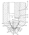
周知の噴射ノズルの一つ、例えば図1に図示されたVCO(バルブ被覆オリフィス)タイプでは、バルブニードル10が移動自在であるノズルボデーボア14の内面によって画定される当接面13と嵌合する当接「ライン」12をバルブニードル10が有する。使用時、バルブニードル10が当接面13から離間すると、噴射ノズル出口16が開口して関連のエンジンシリンダへ高圧燃料を噴射させる。バルブニードル10が当接面13との嵌合状態へ移動すると、出口16が閉じられて噴射が終了する。
In one known injection nozzle, for example the VCO (Valve Covered Orifice) type shown in FIG. 1, the
VCOタイプノズルの利点は、バルブニードル10が出口16を被覆するためバルブニードルが閉じると噴射が急速に停止することである。これを、小さな「サック」つまりノズルボアのブラインド端部に画定された空間から出口が延出する「サックタイプ」ノズルと比較する。サックタイプノズルでは、バルブニードルがサックへの燃料の流れを遮断するに過ぎないので、噴射の終了に続いて、少量の残留燃料がサックに残って燃焼室へ漏出する。排気中の未燃焼または部分燃焼の燃料の量が減少するので、環境に有害な排出物質、特に煙と粒子の削減では、噴射事象の急速な中止が重要である。そのうえ、VCOタイプノズルではサックタイプノズルのサックを実質的に省略できるため、噴射事象後のバルブニードルシート13と噴射ノズル出口との間の燃料の残留を削減する。この低い「封入量」のため、排出物質がさらに改善される。
The advantage of the VCO type nozzle is that the injection stops rapidly when the valve needle closes because the
VCOタイプノズルは特別な長所を備えてはいるが、認識されている問題は、バルブニードルが出口を閉塞するので、ニードル上昇値が低いと、バルブニードルの表面と出口との間の限定された間隙が出口への燃料の流れを制限して、そのため高い流量が妨害されることである。バルブニードルが当接面から上昇する時に当接ラインと当接面との間に画定される環状間隙のために、燃料の流れはさらに制限される。 Although VCO type nozzles have special advantages, a recognized problem is that the valve needle closes the outlet, so a low needle lift value has limited the space between the valve needle surface and the outlet. The gap restricts the flow of fuel to the outlet, thus hindering high flow rates. Due to the annular gap defined between the abutment line and the abutment surface as the valve needle rises from the abutment surface, the fuel flow is further limited.
しかし、噴射装置アクチュエータのエネルギー効率の上昇という付加的な利点とともに、粒子排出物質の削減という長所が実現するので、ニードル上昇が比較的低い時にVCOタイプノズルにおいて高い流量を達成することが望ましい。これは特に、ニードルをその当接部から上昇させるのに必要なエネルギーが圧電スタックによって提供される直接操作圧電VCOタイプ噴射装置ノズルにおいて重要である。 However, it is desirable to achieve a high flow rate in a VCO type nozzle when the needle lift is relatively low, since the advantage of reduced particle emissions is realized with the added benefit of increased energy efficiency of the injector actuator. This is particularly important in directly operated piezoelectric VCO type injector nozzles where the energy required to raise the needle from its abutment is provided by the piezoelectric stack.
本発明がなされたのはこの背景に基づいてであって、上述した問題の幾つかを実質的に回避するか、あるいは少なくとも軽減する燃料噴射装置を提供することが本発明の目的である。 The present invention was made based on this background, and it is an object of the present invention to provide a fuel injector that substantially avoids or at least reduces some of the problems described above.
本発明の第一の面によれば、ノズルボデーのボアの中で移動自在であるバルブ手段を含む、内燃機関のための噴射ノズルが設けられ、バルブ手段は、少なくとも一つのノズル出口を介した燃料吐出を制御するためシート円錐角度を有する当接面と、ともに嵌合自在である第1シートおよび第2シートを有し、第1シートは第1供給室から吐出室への燃料の吐出を制御し、第2シートは第2供給室から吐出室への燃料の吐出を制御し、第2供給室はバルブ手段の中に画定された流路により第1供給室と連通状態にあって、第1および第2シートが当接面から解離すると、第1および第2シートを越えて少なくとも一つのノズル出口へ燃料が流入できる。 According to a first aspect of the present invention, there is provided an injection nozzle for an internal combustion engine, including valve means movable in a bore of a nozzle body, the valve means being fuel via at least one nozzle outlet. A contact surface having a seat cone angle for controlling discharge and a first sheet and a second sheet that can be fitted together, and the first sheet controls the discharge of fuel from the first supply chamber to the discharge chamber. The second sheet controls the fuel discharge from the second supply chamber to the discharge chamber, and the second supply chamber is in communication with the first supply chamber by the flow path defined in the valve means, When the first and second sheets are dissociated from the contact surface, fuel can flow into the at least one nozzle outlet beyond the first and second sheets.
バルブ手段は、バルブ部材の形を取ることが望ましい。 The valve means preferably takes the form of a valve member.
吐出室の空間は、第1および第2シートの中間でバルブ部材に設けられた環状溝によって一部画定される。 The space of the discharge chamber is partly defined by an annular groove provided in the valve member between the first and second sheets.
吐出室を介したノズル出口への燃料の流れは第1および第2シートによって制御されるので、単一のシートを有する従来のVCOタイプノズルと比較して高い燃料流量が可能である。そのうえ、第1供給室に対して上流と下流の両方向から出口へ燃料が流入できるので、燃焼室へ噴射される燃料スプレーの均衡が改善される。 Since the flow of fuel to the nozzle outlet through the discharge chamber is controlled by the first and second sheets, a high fuel flow rate is possible compared to a conventional VCO type nozzle having a single sheet. In addition, since fuel can flow into the outlet from both the upstream and downstream directions with respect to the first supply chamber, the balance of the fuel spray injected into the combustion chamber is improved.
本発明の一実施例では、第1シートは第1当接ラインの形を取り、バルブ部材は、第1円錐角度を画定する円錐台形の第1バルブ領域を含む。環状溝はまた、第2円錐角度を画定する円錐台形の第1溝領域を含む。第1および第2円錐角度は、第1バルブ領域と第1溝領域の相互界面に第1当接ラインを画定するように選択されるとよい。 In one embodiment of the invention, the first seat takes the form of a first abutment line and the valve member includes a frustoconical first valve region defining a first cone angle. The annular groove also includes a frustoconical first groove region that defines a second cone angle. The first and second cone angles may be selected to define a first abutment line at the mutual interface between the first valve region and the first groove region.
第1円錐角度とシート円錐角度とが第1角度差を間に画定して、第2円錐角度とシート円錐角度とが第2角度差を間に画定し、シートの磨耗を最小にするとともに第1当接ラインの移動を回避するため、第1および第2角度差はほぼ同じになるように選択されるとよい。 The first cone angle and the seat cone angle define a first angle difference in between, the second cone angle and the seat cone angle define a second angle difference in between to minimize seat wear and In order to avoid movement of one abutment line, the first and second angular differences may be selected to be substantially the same.
代替実施例では、第1シートは、第1バルブ領域と第1溝領域との相互界面に画定される第1当接ラインではなく、第1バルブ領域によって画定されるシート範囲の形を取る。 In an alternative embodiment, the first seat takes the form of a seat area defined by the first valve area rather than a first abutment line defined at the mutual interface between the first valve area and the first groove area.
第2シートも第2当接ラインの形を取り、したがってバルブ部材は第4円錐角度を画定する円錐台形の第2バルブ領域を含んでもよい。環状溝も、第3円錐角度を画定する円錐台形の第2溝領域を含む。第3および第4円錐角度は、第2バルブ領域と第2溝領域との相互界面に第2当接ラインを画定するように選択されるとよい。 The second seat also takes the form of a second abutment line, and thus the valve member may include a frustoconical second valve region defining a fourth cone angle. The annular groove also includes a frustoconical second groove region that defines a third cone angle. The third and fourth cone angles may be selected to define a second abutment line at the mutual interface between the second valve region and the second groove region.
第1シートに関して説明したように、第3円錐角度とシート円錐角度とが第3角度差を間に画定して、第4円錐角度とシート円錐角度とが第4角度差を間に画定し、シートの磨耗を最小にするとともに第2当接ラインの移動を回避するため、第3および第4角度差はほぼ同じになるように選択されるとよい。 As described with respect to the first seat, the third cone angle and the seat cone angle define a third angle difference in between, the fourth cone angle and the seat cone angle define a fourth angle difference in between, To minimize seat wear and avoid movement of the second abutment line, the third and fourth angular differences may be selected to be approximately the same.
あるいは第2シートは、第2バルブ領域と第2溝領域との相互界面に画定される第2当接ラインではなく、第2バルブ領域によって画定されるシート領域であってもよい。 Alternatively, the second seat may be a seat region defined by the second valve region instead of the second contact line defined at the mutual interface between the second valve region and the second groove region.
噴射のための加圧燃料が流路によって第1供給路から第2供給路へ供給されることは、本発明の特徴である。流路は、少なくとも部分的にバルブ部材に沿って延在して第2供給室と連通状態にある一端部を有する軸方向通路を含むことが望ましい。第2供給室はボアのブラインド端部に画定されることが望ましい。 It is a feature of the present invention that pressurized fuel for injection is supplied from the first supply path to the second supply path by the flow path. Desirably, the flow path includes an axial passage having one end extending at least partially along the valve member and in communication with the second supply chamber. The second supply chamber is preferably defined at the blind end of the bore.
流路はまた、バルブ部材に設けられた少なくとも1本の径方向通路を含み、径方向通路は第1供給室と軸方向通路との間を連通させる。そのため、加圧燃料が第2供給室と常に連通状態にあることが理解できるだろう。 The flow path also includes at least one radial passage provided in the valve member, which communicates between the first supply chamber and the axial passage. Therefore, it will be understood that the pressurized fuel is always in communication with the second supply chamber.
バルブ部材の二つのシートの密封を同時に確実に行うように両シートを製造することは効率的な製造には実行不可能であると認識されている。そのため本発明の第二の面によれば、第1シートと軸方向通路とを有するバルブ部材を含む内燃機関のための噴射ノズルが設けられ、第2シートを有するインサート部材が軸方向通路に収容され、両シートはノズル出口を介した燃料吐出を制御するため当接面と嵌合自在であり、第1シートは第1供給室から吐出室への燃料の吐出を制御するとともに、第2シートは第2供給室から吐出室への燃料の吐出を制御し、第2供給室は、バルブ部材の中に画定された流路によって第1供給室と連通状態にある。 It has been recognized that manufacturing both seats to ensure that the two seats of the valve member are sealed simultaneously is not feasible for efficient manufacturing. Therefore, according to the second aspect of the present invention, an injection nozzle for an internal combustion engine including a valve member having a first seat and an axial passage is provided, and an insert member having a second seat is accommodated in the axial passage. The two sheets are freely engageable with the contact surface to control fuel discharge through the nozzle outlet, and the first sheet controls the discharge of fuel from the first supply chamber to the discharge chamber, and the second sheet. Controls the discharge of fuel from the second supply chamber to the discharge chamber, the second supply chamber being in communication with the first supply chamber by a flow path defined in the valve member.
インサート部材によって第2シートが設けられるので、第1および第2シートがほぼ同時に密封されるように、第1シートがバルブ部材そのものに設けられるのに対してインサート部材が適切に配置されて第2シートを確立するような、手頃な製造技術が必要である。 Since the second seat is provided by the insert member, the first seat is provided on the valve member itself so that the first and second seats are sealed almost simultaneously, whereas the insert member is appropriately disposed and the second seat is provided. Affordable manufacturing techniques are needed to establish the sheet.
本発明の第一の面の噴射ノズルと同じように、バルブ部材は、第1円錐角度と第2バルブ領域とを画定する円錐台形と、第2円錐角度を画定する円錐台形の第1バルブ領域を含む。第1シートは第2バルブ領域によって画定されるシート範囲であることが望ましい。 Similar to the injection nozzle of the first aspect of the present invention, the valve member comprises a frustoconical shape defining a first conical angle and a second valve region, and a frustoconical first valve region defining a second conical angle. including. The first seat is preferably a seat area defined by the second valve region.
インサート部材は、第3円錐角度を画定する円錐台形の第1インサート領域と、第4円錐角度を画定する円錐台形の第2インサート領域とを含み、第2インサート領域によって第2シートが画定されることが望ましい。また、第1インサート領域と第2バルブ領域とが吐出室の空間を画定するように、第2および第3円錐角度が選択される。 The insert member includes a frustoconical first insert region defining a third cone angle and a frustoconical second insert region defining a fourth cone angle, and the second insert region defines a second sheet. It is desirable. Also, the second and third cone angles are selected so that the first insert region and the second valve region define a discharge chamber space.
そのため本発明による噴射ノズルは、ニードル上昇値が低い時に高い燃料流量が得られるとともにスプレー特徴が改善されるという利点を維持しながら、インサート部材によって製造がさらに容易になることが理解できるだろう。 Thus, it will be appreciated that the injection nozzle according to the present invention is easier to manufacture with the insert member while maintaining the advantages of higher fuel flow rates and improved spray characteristics when the needle rise value is low.
さて、添付図面を参照して、本発明を単なる例として説明する。 The present invention will now be described by way of example only with reference to the accompanying drawings.
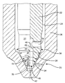
図2を参照すると、図1に図示されたノズルに対して改良された燃料吐出特性を提供する本発明の第一実施例の噴射ノズルが図示されている。全体として20で示された噴射ノズル20は、ノズルボデー26に設けられたブラインドボア24の中で摺動自在であるとともに、ボア24によって画定される円錐形当接面28と嵌合自在であって関連する燃焼スペースまたはシリンダ(不図示)への燃料噴射を制御するバルブ部材またはニードル22の形のバルブ手段を含む。当接面28はシート円錐角度θSを画定する。
Referring to FIG. 2, there is illustrated a first embodiment of an injection nozzle of the present invention that provides improved fuel delivery characteristics relative to the nozzle illustrated in FIG. The
バルブニードル22は、直接圧電作用によって、あるいは圧電作用による制御バルブ装置(不図示)によって移動自在である。またあるいは、バルブニードルは電磁または油圧手段によって作動してもよい。バルブニードル22がボア内で移動する方法は、この技術分野の熟練者には熟知されている。
The
円錐形当接面28からノズルボデー26の外面へ径方向に延出することで、噴射ノズル吐出室34から燃焼室(不図示)への高圧燃料の流路となる少なくとも第1組ノズル出口30が、ノズルボデー26に設けられている。ここでは第1組出口30のみが図示されているが、一組以上の出口30を設けてもよいことは理解できるだろう。出口30が吐出室34にほぼ整合状態で開口するように、当接面28とともに吐出室34の空間を部分的に画定する環状溝または凹部44がバルブニードル22に設けられているが、その長所については後述する。
By extending in a radial direction from the
本発明のこの実施例のバルブニードル22は、5個の個別領域を備える。図2に図示されたステム領域27は、ほぼ円筒形であってバルブニードル22のステムを構成する。当該技術ではよく見られるように、バルブニードルの移動を制御するため、バルブニードル22の上端部にはある形の制御装置(不図示)が設けられている。
The
第1円錐台形バルブ領域29は、ステム領域27のすぐ下流に配置されて第1円錐角度θ1を画定する。第1領域29のすぐ下流においてバルブニードル22は、環状溝44の一部を成して第2円錐角度θ2を画定する第1円錐台形溝領域31を含む。バルブ領域29と溝領域31とはともに、これらの相互界面において、本実施例では環状当接ラインである第1シート36を画定する。第1当接ライン36は、第1当接ライン36の上流に位置する第1供給室38から吐出室34への燃料の流れを制御するため当接面28と嵌合自在である。第1供給室38は、ノズルボデー26のボア24とバルブニードル22の外面との間に画定される。使用時、第1供給室38には例えば共通レール燃料供給源から周知の方法で、噴射のための加圧燃料が供給される。
The first
第3円錐角度θ3を画定する第2円錐台形溝領域33は、第1溝領域31のすぐ下流に配置されて、第2バルブニードルシート40をその下流エッジに画定する。この実施例では、第2シート40は環状当接ラインであり、第2供給室42から吐出室34への燃料の流れを制御するように当接面28と嵌合自在である。第2供給室42は第1供給室38の下流に位置し、ボア24のブラインド端部によって画定される。吐出室34の空間は、出口30とほぼ整合するように、第1および第2溝領域31,33(つまり第1当接ライン36と第2当接ライン40との中間)によって部分的に画定される。
A second
バルブニードル22は、第4円錐角度θ4を画定して、この実施例では面取りされたニードル先端を構成する第2バルブ領域35を終端とする。第2バルブ領域35は、ボア24のブラインド端部に画定されたサック空間へ延出し、ノズルボデーボア24とともに第2供給室42を画定する。
The
ブラインドボアまたは通路46はニードル22の先端の開口部48から軸方向に延出し、円筒形ステム領域27に設けられた径方向穿孔または通路54によって第1供給室38と連通する。径方向通路54は、第1供給室38と第2供給室42との間に「T字形」の燃料流路を形成するように、軸方向通路46と交差している。
A blind bore or
環状溝44は第1および第2溝領域31,33を画定し、溝領域31,33は、溝の最深部が相互界面32に画定されるような形状を持つ。これを達成するため、第1溝領域31によって画定される円錐角度θ2は当接面28によって画定される円錐角度θSより大きく、第2溝領域33の円錐角度θ3は、当接面28によって画定される円錐角度θSより小さい。
The
燃焼室へ燃料を噴射する必要がある時には、第1および第2当接ライン36,40が当接面28から離間するようにバルブニードル22が作動する、つまり上昇する。第1当接ライン36が当接面28から上昇すると、第1供給室38から、第1当接ライン36と当接面28との間に形成された環状間隙を越えて出口30を通り、燃焼室へ、第1流路を燃料が流れる。
When it is necessary to inject fuel into the combustion chamber, the
同時に、当接面28から上昇した第2当接ライン40によって第2流路が確立され、第1供給室38から径方向通路54と軸方向通路46とを介し、下流の第2供給室42へと燃料が流れる。次に燃料は、第2供給室42から、第2当接ライン40と当接面28との間に形成された環状間隙を通り吐出室34へ流れて、出口30を通り燃焼室へ流れる。
At the same time, a second flow path is established by the
以上の説明から、一方は第1供給室38から直接的に第1当接ライン36を越え、一方は第1供給室38から通路46,54と第2供給室42とを介して間接的に第2当接ライン40を越える2本の流路によって、所与のニードル上昇に対して出口30から噴射される燃料の量がかなり上昇することが理解できるだろう。そのため、特にニードル上昇レベルが低い場合には、図1で例示した従来のVCOタイプノズルと比較して、出口30への燃料の流れが増大する。
From the above description, one crosses the
上述した装置のさらなる利点は、相対的な上流と下流の両方から同時に、燃料が吐出室34と出口30の入口へ流入できることである。こうして、例えば図1に図示されたような、出口16の上流側へ燃料供給が付勢される従来のVCOタイプノズルとは対照的に、出口30への燃料供給はほぼ対称となる。出口への燃料の供給がより均一に、つまりほぼ対称となると、燃焼室への燃料スプレーの均衡が改善され、これが排気中で発生する煙を減少させる。
A further advantage of the device described above is that fuel can flow into the
二つの当接ライン36,40と第2流路(つまり通路46,54を通る)とを設けることにより総流面積が増大することは明らかだろう。そのうえ、環状溝44を出口30とほぼ整合状態に配置することにより、流れの制限が減少して燃料の流れが増大する。出口30の入口とバルブニードル22との間の間隙が大きいので燃料の流れが増大する。そのため、出口30に近接して環状溝44を設けることで、周知のVCOタイプノズルに共通する流れの制限という不都合な作用を軽減する。
It will be apparent that the total flow area is increased by providing two
さらなる利点は、環状溝44を出口30とのほぼ整合状態に位置決めすることにより、出口30への燃料の流れがバルブニードル22の径方向偏心による影響をあまり受けないので、ノズルのスプレー特性が均一性つまり「均衡」を改善されることである。これは、燃焼室における燃料の連続的な燃焼を保証するとともに、排気の煙を減少させる。
A further advantage is that by positioning the
第2供給室42は第1供給室38と連通状態にあるので、第2供給室42には常に噴射圧の燃料が供給されることは、熟練した読者には明らかだろう。そのため、加圧燃料は第2バルブ領域35に作用して、バルブニードル22が当接面28から離間し始めると、バルブニードル22に付加的な上昇力を付与し、こうして(例えば圧電アクチュエータにより)ニードルを上昇させるに必要なエネルギーを減少させる。噴射終了時に、ニードルによって変位した燃料は、第1シート36へ逆方向に送られるのでなく軸方向通路46に収容されるため、バルブニードルの閉口を助けるという点で、第2供給室42はさらなる利点を提供する。
As the
軸方向通路46は、燃料の第2流路となるとともに、第1または第2当接ライン36,40の寸法の若干の偏心をノズルボデー26が補いながらも、非噴射位置にある間に有効な密封を行うように、バルブニードル22に横方向可撓性を付与する。
The
第1当接ライン36を画定する第1バルブ領域29および第1溝領域31と、第2当接ライン40を画定する第2バルブ領域35と第2溝領域33との寸法およびそれぞれの円錐角度とは、第1および第2当接ライン36,40の各々の上流側と下流側の両方においてシートの磨耗がほぼ等しい量で発生するように選択される。シートの磨耗を確実に均衡にすると、噴射装置の吐出ドリフトを回避するか、少なくとも最小にする。これを達成するため、図2aに拡大図示されているように、第1バルブ領域29の円錐角度θ1とシート円錐角度θSとの間の角度差△θ1と、第1溝領域31の円錐角度θ2とシート円錐角度θSとの間の△θ2と、第2溝領域33の円錐角度θ3とシート円錐角度θSとの間の△θ3と、第2バルブ領域35の円錐角度θ4とシート円錐角度θSとの間の△θ4とは、比較的小さく、一般的にはおよそ0.5°から30°となるように選択される。
Dimensions of the
図3は燃焼噴射装置ノズルの代替実施例を示し、図2に図示されたものに類似した部品には同様の参照数字が付けられている。図3のノズルの特徴の多くは、図2のものと同一であるため、再び詳述しない。 FIG. 3 shows an alternative embodiment of a combustion injector nozzle, with parts similar to those shown in FIG. 2 having similar reference numerals. Many of the features of the nozzle of FIG. 3 are the same as those of FIG. 2 and will not be described in detail again.
図2の実施例と対照的に、図3の実施例は、ニードル上昇値が低い状態で燃料流量を最大にするように、容積が増大した吐出室34を備えている。すでに説明したように、VCOタイプノズルは、バルブ当接ラインと当接面との間だけでなく、バルブニードルと出口との間の制限された間隙により、燃料の流れが制限されるので、ニードル上昇値が低い時に流量が制限される傾向がある。
In contrast to the embodiment of FIG. 2, the embodiment of FIG. 3 includes a
本発明のこの実施例では、角度差△θ2と△θ3とが増大して環状溝44が深くなっているため、吐出室34の空間を拡張する。そのうえ、ニードルが当接する時に、第2溝領域33と第1溝領域31との相互界面32が出口30との整合状態から下流方向に若干オフセットするように、第2溝領域33の軸方向長さは第1溝領域31の軸方向長さより短い。そのため、ニードル上昇値が比較的低い時には、環状溝44の最深部が出口30とほぼ整合して、燃料の流れとスプレー分布とを改善することは明らかであろう。
In this embodiment of the present invention, the angular difference Δθ2 and Δθ3 increase and the
環状溝44をさらに深くすると、出口30への燃料の制限をさらに軽減して燃料スプレー特性を改善するのに対して、角度差θ2と△θ3の増大は、2本の当接ライン36,40の磨耗を増大させる作用も持つ。これは、「有効」当接ラインを上流と下流のいずれかの方向に移動させてノズルの「開口圧」に影響するので、溝44の深さを適切に選択することが重要である。
Deepening the
さらに、吐出ドリフトを最小にするには、角度差△θ1,△θ2,△θ3,△θ4をできるだけ小さくなるように選択することが望ましい。このため、図4は本発明のさらなる実施例を示し、やはり、上述したものに類似した部品には同様の参照番号が付けられている。図4において、バルブニードル22は、第1バルブ領域29のすぐ上流に位置して円錐角度θ5を画定する別の円錐台形領域37を備える。ここでは第1バルブ領域29の円錐角度θ1は、シート円錐角度θSとほぼ同じであるという点で前の前出実施例のものと異なる円錐角度θ1を画定する。そのためバルブニードル22は、前出実施例のように当接ラインにおいてではなく、第1バルブ領域29の円錐台形の表面範囲によって当接面28と当接する。しかし実際には、この実施例の第1バルブ領域29の円錐角度θ1はシート円錐角度θSと若干異なるように選択されるため、第1バルブ領域29のどのエッジが最初に当接面28と接触するかが分かる。
Further, in order to minimize the discharge drift, it is desirable to select the angle differences Δθ1, Δθ2, Δθ3, and Δθ4 as small as possible. For this reason, FIG. 4 shows a further embodiment of the present invention, again parts similar to those described above are given similar reference numerals. In FIG. 4, the
第1バルブ領域29と第1溝領域31の円錐角度θ1,θ2との間の差はそれぞれ、図2と3の実施例と比較すると減少しているため、シートの移動が軽減するかほぼ回避されることが分かるだろう。
Since the difference between the cone angles θ1 and θ2 of the
同様に図5の実施例では、円錐角度θ4とシート円錐角度θSとの間の角度差△θ4を最小にするため、第2バルブ領域35の円錐角度θ4が減少している。実際に図5では、前出実施例のように第2当接ラインではなく、第2バルブ領域35の円錐台形表面範囲によってバルブニードル22が当接面28と当接するように、円錐角度θ4はシート円錐角度θSとほぼ同じになるように設定されている。第2バルブ領域35に設ける円錐角度θ4を小さくすると、第2シート40への負荷が低下してシートの移動を軽減または回避する。第1および第2溝領域31,33の配置が吐出室34の寸法を決め、そのため、シートの耐久性を損なうことなく吐出室34の空間を最適化できる。例えば図5の実施例に見られるように、第1および第2溝領域31,33の軸方向長さは、前出実施例と比較して短い。例を挙げるとこの実施例では、ニードル上昇値が低い時に燃料の流れに対する制限を軽減するように、吐出室34の奥行が増大している。しかし、第1および第2溝領域31,33の軸方向長さが減少しているので、吐出室34の容積が最小となり、低い「封入量」によって達成される利点が保たれる。
Similarly, in the embodiment of FIG. 5, the cone angle θ4 of the
溝領域31,33を画定する溝44の形状のため、吐出室34は断面が三角形の輪郭を持つが、吐出室34の輪郭が例えば湾曲する(つまり湾曲溝となる)ようにバルブニードル22を形成してもよいことは理解できるだろう。
Due to the shape of the
上述したように、噴射装置ノズルの設計では、ニードル上昇値が低い時に高い流量を達成することの重要性がますます重要となっている。シート円錐角度θSとともに円錐台形領域29,31,33,35の円錐角度を増大することにより、所与のニードル上昇値に対して達成される流面積が増大することが分かるだろう。
As mentioned above, in the design of injector nozzles, the importance of achieving high flow rates when the needle rise value is low becomes increasingly important. It can be seen that increasing the cone angle of the
両シート36,40がほぼ同時に当接面28と確実に嵌合するために上述した実施例で必要とされる正確なニードル円錐角度とシート直径を達成するには、非常に正確な製造技術が必要とされることは、熟練者には理解できるだろう。図6に例示された本発明の別の実施例では、前出実施例に関連して説明したようなノズルの利点を残しているが、このような噴射装置の機械加工に関連した製造要件を軽減するノズル装置が図示されている。
In order to achieve the exact needle cone angle and seat diameter required in the above-described embodiment to ensure that both
図6は別の代替ノズル装置を示し、前と同様に多くの部品が前出実施例と類似しているため同様の参照番号が付けられている。 FIG. 6 shows another alternative nozzle arrangement which, like before, has the same reference numerals since many parts are similar to the previous embodiment.
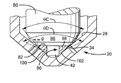
本発明の前出実施例のように、円錐形当接面28からノズルボデー26の外面へ径方向に延在して、ノズルボデー26内部の第1供給室38から関連するシリンダまたは燃焼室への燃料の流路を設ける少なくとも第1組の出口30がノズルボデー26に設けられている。バルブニードル22が少なくとも5個の個別領域を画定して二つのシート36,40を含む本発明の前出実施例と対照的に、この実施例のバルブニードル80は3個の個別領域を画定するような形状を持ち、第1バルブニードルシート82のみを含む。
As in the previous embodiment of the present invention, fuel extends radially from the
最初に、略円筒形領域84はバルブニードル80の先端の上流に位置し、バルブニードル80のステムを構成する。円錐台形の第1バルブ領域86は円筒形領域84のすぐ下流に設けられて、第1円錐角度θAを画定する。第1バルブ領域86のすぐ下流において、バルブニードル80は、第2円錐角度θBを画定するとともに、バルブニードル80の終端である下流エッジ83を有する第2円錐台形バルブ領域88を含む。この実施例では、θBはシート円錐角度θSとほぼ同じであるため、第2バルブ領域88は円錐台形の表面の範囲にわたって第1シート82となる。図6ではバルブニードル80は第2バルブ領域88の表面範囲に当接すると図示されているが、第2バルブ領域88の円錐角度θBはθ円錐角度θSより大きくてもよく、その場合には、第1バルブ領域86の下流エッジ89に当接ラインが確立されることは理解できるだろう。
Initially, the generally
ニードルが当接して、ニードル80に設けられた軸方向延在通路つまりブラインドボア92の一端部に開口部90を画定する時、第2領域88の下流エッジ83は出口30の上流エッジとほぼ整合する。軸方向通路92は、円筒形領域84とバルブニードル80のステムとに部分的に延在する。径方向穿孔または通路94が円筒形第1領域84に設けられ、第1供給室38から第2供給室42へ燃料の「T字形」流路を設けるように軸方向通路92と交差する。
When the needle abuts and defines an
軸方向通路92は、本発明の前出実施例と比較して拡張された断面積範囲を有し、バルブニードル80の開口部90の中に同軸に配置されて開口部から突出する管形の円筒形インサート部材96を収容する。インサート部材96は、通路92との締まりばめ状態にあることが望ましい。
The
図6aでさらにはっきりと分かるように、インサート部材(全体として96で示される)は、バルブニードル80へ挿入された時にノズルの第2シート102となるように製造中に機械加工される下流端面を有する。これを達成するため、インサート部材96の下端部は、第3円錐角度θCを画定する円錐台形の第1インサート領域98を含む。インサート部材96は、第1インサート領域98のすぐ下流に位置する円錐台形の第2インサート領域100を終端とする。第2インサート領域100は、シート円錐角度θSとほぼ同じである円錐角度θDを画定する。そのため、第2インサート領域100の円錐台形の表面範囲により、インサート部材96は当接面28に当接する。円錐角度θDも、シート円錐角度θSより大きくなるように選択され、その場合には、第1および第2インサート領域98,100の間の相互界面に当接ラインが画定されることが分かるだろう。
As can be seen more clearly in FIG. 6a, the insert member (generally indicated at 96) has a downstream end face that is machined during manufacture to become the
図6と6aとに図示された位置では、インサート部材96のシート102は当接面28と嵌合し、そのため、第1シート82とともに、上流と下流の両方向からの燃料の流入に対して出口30を密封する。
6 and 6a, the
本発明のこの実施例では、バルブニードル80の第2領域88の周縁エッジと第1インサート領域98との間に狭い径方向間隙‘g’が存在するように、インサート部材96の第1インサート領域98の円錐角度θCが選択される。そのため、インサート部材96とバルブニードル80とが組み立てられてノズルボデー26へ挿入されると、出口30とほぼ整合した状態で吐出室34が形成される。そのため本発明のこの実施例では、製造要件を軽減しながら、第1および第2シート82,102の存在と吐出室34の存在とに関連する利点が維持される。実際には、第1および第2シート82,102を別々の部品に機械加工する際に求められる公差は、単一のバルブニードルに両シートを形成する場合よりも緩やかである。
In this embodiment of the invention, the first insert region of the
この実施例のノズル20を組み立てるには、図7に図示されているように、インサート部材96の上流開口部106よりも大きいが軸方向通路92の直径よりも小さい直径を持つボール104が、上流開口部106と当接するように設けられる。ボール104は、非噴射位置にある時に第1および第2シート82,102が同時に密封を行うように、インサート部材96をバルブニードル80の中に正しく位置決めするのに使用される。
To assemble the
ノズル20の組立中、第1シート82が当接面28と嵌合する時に当接面28から解離するように、インサート部材96はバルブニードル80の軸方向通路92へ付勢される。次に、第1供給室38へ燃料圧力が供給される。ボール104は上流インサート開口部106を閉塞することで軸方向通路92を閉塞するので、インサート部材96の第2シート102が当接面28と嵌合するように、燃料圧力はボール104とインサート部材96とを下流方向に押圧する。インサート部材96がこのように正しく位置決めされると、ノズル20が分解されて、一緒にボール104がバルブニードル80から取り外される。こうしてバルブニードル80は、最終組立と取付けのための正しい配置となる。
During assembly of the
代替組立プロセスでは、バルブニードル80がノズルボデー26へ挿入される時に第2シート102が当接面28と嵌合するが第1シート82は嵌合しないように、最初にインサート部材96が部分的に通路92へ押入される。次に、第1シート82が当接面28と嵌合するまでインサート96がさらに通路92へ押入されるように、バルブニードル80が付勢される。
In an alternative assembly process, the
特許請求の範囲に規定された本発明の範囲から逸脱せずに様々な変形と改良を本発明に加えてもよいことは、本発明を実行する者と当該技術の熟練者には理解できるだろう。したがって、本発明の範囲を判断する際には、上述した特定の説明ではなく、特許請求の範囲およびその中の概念的記載を参考にすべきである。 It will be apparent to those skilled in the art and those skilled in the art that various modifications and improvements may be made to the present invention without departing from the scope of the invention as defined in the claims. Let's go. Therefore, in determining the scope of the present invention, the claims and the conceptual description therein should be referred to, not the specific description above.
10 バルブニードル
12 当接ライン
13 当接面
14 ノズルボデーボア
16 噴射ノズル出口
20 噴射ノズル
22 バルブ部材
24 ブラインドボア
26 ノズルボデー
27 ステム領域
28 円錐形当接面
29 第1円錐台形バルブ領域
30 ノズル出口
31 第1円錐台形溝領域
33 第2円錐台形溝領域
34 噴射ノズル吐出室
35 第2バルブ領域
36 第1当接ライン
37 別の円錐台形領域
38 第1供給室
40 第2当接ライン
42 第2供給室
44 環状溝
46 ブラインドボア
48 開口部
54 径方向通路
80 バルブニードル
82 第1バルブニードルシート
83 第2円台形バルブ領域の下流エッジ
84 第1略円筒形領域
86 第1バルブ領域
88 第2円錐台形バルブ領域
89 第1バルブ領域の下流エッジ
90 開口部
92 ブラインドボア
94 径方向穿孔
96 円筒形インサート部材
98 第1インサート領域
100 第2インサート領域
102 シート
104 ボール
106 上流開口部
DESCRIPTION OF
Claims (14)
前記シート円錐角度(θS)より小さい角度を持つ第1円錐角度(θ1)を画定する円錐台形の第1バルブ領域(29)と、
前記シート円錐角度(θS)より大きな角度を持つ第2円錐角度(θ4)を画定する円錐台形の第2バルブ領域(35)と、
少なくとも一つのノズル出口(30)と連通状態にある吐出室(34)を部分的に画定する環状溝(44)とを含み、
前記環状溝(44)が前記第1および第2バルブ領域(29,35)の中間にそれぞれ設けられているため、第1当接ライン(36,82)が、該第1バルブ領域(29)と前記環状溝(44)との間の相互界面に画定されるとともに、第1供給室(38)から前記吐出室(34)への燃料の吐出を制御可能に前記当接面(28)と嵌合自在であり、第2当接ライン(40,102)が、該第2バルブ領域(35)と該環状溝(44)との間の相互界面に画定されるとともに、第2供給室(42)から該吐出室(34)への燃料の吐出を制御するように該当接面(28)と嵌合自在であり、該第2供給室(42)が、前記バルブ部材(22,80,96)の中に画定された流路(46,54;92,94)によって該第1供給室(38)と連通状態にあり、
前記第1および第2当接ライン(36,40;82,102)が前記当接面(28)から解離すると、該第1および第2当接ライン(36,40;82,102)を越えて前記少なくとも一つのノズル出口(30)へ燃料が流入でき、
前記流路(46,54;92,94)が、前記バルブ部材(22,80)に沿って少なくとも部分的に延在する軸方向通路(46,92)を含み、該軸方向通路の一端部が前記第2供給室(42)と連通しており、
前記流路(46,54;92,94)が、前記バルブ部材(22,80)に設けられた少なくとも1本の径方向通路(54,94)を含み、該径方向通路(54,94)が、前記第1供給室(38)と該軸方向通路(46,92)との間を連通させる噴射ノズル。 An injection nozzle for an internal combustion engine, which defines a seat cone angle (θS) and a single valve member (22, 80, 96) movable within a bore (24) of a nozzle body (26). A nozzle including a contact surface (28), wherein the valve member (22, 80, 96) is
A frustoconical first valve region (29) defining a first cone angle (θ1) having an angle smaller than the seat cone angle (θS);
A frustoconical second valve region (35) defining a second cone angle ( θ4 ) having an angle greater than the seat cone angle (θS);
An annular groove (44) partially defining a discharge chamber (34) in communication with at least one nozzle outlet (30);
Since the annular groove (44) is provided in the middle of the first and second valve regions (29, 35), the first contact line (36, 82) is provided in the first valve region (29). And the annular groove (44), and the contact surface (28) is controllable to control the discharge of fuel from the first supply chamber (38) to the discharge chamber (34). A second abutment line (40, 102) is defined at the mutual interface between the second valve region (35) and the annular groove (44), and is fitted in the second supply chamber ( 42) is freely engageable with the corresponding contact surface (28) so as to control the discharge of fuel from the discharge chamber (34), and the second supply chamber (42) includes the valve members (22, 80, 96) is connected to the first supply chamber (38) by a flow path (46, 54; 92, 94) defined in it. It is in the state,
When the first and second contact lines (36, 40; 82, 102) are disengaged from the contact surface (28), the first and second contact lines (36, 40; 82, 102) are exceeded. Fuel can flow into the at least one nozzle outlet (30) ,
The flow path (46, 54; 92, 94) includes an axial passage (46, 92) extending at least partially along the valve member (22, 80), one end of the axial passage. Communicates with the second supply chamber (42),
The flow path (46, 54; 92, 94) includes at least one radial passage (54, 94) provided in the valve member (22, 80), and the radial passage (54, 94). Is an injection nozzle for communicating between the first supply chamber (38) and the axial passage (46, 92) .
第2シート(102)を有するインサート部材(96)が前記軸方向通路(92)に収容され、両シート(82,102)が、前記ノズル出口(30)を通る燃料吐出を制御するように前記当接面(28)と嵌合自在であり、該第1シート(82)が第1供給室(38)から前記ノズル出口(30)と連通した吐出室(34)への燃料の吐出を制御するとともに、該第2シート(102)が前記第2供給室(42)から該吐出室(34)への燃料の吐出を制御し、該第2供給室(42)が前記バルブ部材(80)の中に画定された流路(92,94)によって該第1供給室(38)と連通状態にあり、該第1および第2シート(82,102)が該当接面(28)から解離すると、該第1および第2シート(82,102)を越えて該少なくとも一つのノズル出口(30)へほぼ対称的に燃料が流入できる噴射ノズル。 The nozzle body having a at least one nozzle outlet (30) and the abutment surface (28) (26), and, movable in the bore of the nozzle body (26), single, having a first sheet (82) includes a valve member (80) that the, an injection nozzle for an internal combustion engine,
Insert member having a second sheet (102) (96) is accommodated in said axial passage (92), the sheets (82, 102) comprises to control the fuel discharge through said nozzle outlet (30) The first sheet (82) can be fitted to the contact surface (28) and controls the discharge of fuel from the first supply chamber (38) to the discharge chamber (34) communicating with the nozzle outlet (30). while, the second sheet (102) controls the discharge of fuel in the second supply chamber from (42) to the discharge chamber (34), the second supply chamber (42) said valve member (80) When the first supply chamber (38) is in communication with the flow path (92, 94) defined therein, and the first and second sheets (82, 102) are dissociated from the corresponding contact surface (28). The less than the first and second sheets (82,102) Injection nozzle can be almost symmetrically flowing fuel into one nozzle outlet (30) also.
Applications Claiming Priority (1)
| Application Number | Priority Date | Filing Date | Title |
|---|---|---|---|
| EP04250132A EP1555430B1 (en) | 2004-01-13 | 2004-01-13 | Injection nozzle |
Publications (2)
| Publication Number | Publication Date |
|---|---|
| JP2005201272A JP2005201272A (en) | 2005-07-28 |
| JP4194564B2 true JP4194564B2 (en) | 2008-12-10 |
Family
ID=34610218
Family Applications (1)
| Application Number | Title | Priority Date | Filing Date |
|---|---|---|---|
| JP2005004483A Expired - Fee Related JP4194564B2 (en) | 2004-01-13 | 2005-01-11 | Injection nozzle |
Country Status (5)
| Country | Link |
|---|---|
| US (1) | US7168412B2 (en) |
| EP (1) | EP1555430B1 (en) |
| JP (1) | JP4194564B2 (en) |
| AT (1) | ATE350575T1 (en) |
| DE (1) | DE602004004056T2 (en) |
Cited By (3)
| Publication number | Priority date | Publication date | Assignee | Title |
|---|---|---|---|---|
| US9816445B2 (en) | 2014-02-28 | 2017-11-14 | Mazda Motor Corporation | Device for controlling direct-injection gasoline engine |
| US9874173B2 (en) | 2014-02-03 | 2018-01-23 | Mazda Motor Corporation | Control device for direct injection gasoline engine |
| DE112016001346B4 (en) | 2015-03-23 | 2021-12-16 | Mazda Motor Corporation | Fuel injection control device for direct injection engine |
Families Citing this family (15)
| Publication number | Priority date | Publication date | Assignee | Title |
|---|---|---|---|---|
| DE102005009148A1 (en) * | 2005-03-01 | 2006-09-07 | Robert Bosch Gmbh | Fuel injector with direct-acting injection valve member with double seat |
| US7578450B2 (en) | 2005-08-25 | 2009-08-25 | Caterpillar Inc. | Fuel injector with grooved check member |
| DE112006002264T5 (en) * | 2005-08-25 | 2008-06-26 | Caterpillar Inc., Peoria | Fuel injection device with check member with groove |
| US7360722B2 (en) | 2005-08-25 | 2008-04-22 | Caterpillar Inc. | Fuel injector with grooved check member |
| BRPI0806694A2 (en) * | 2007-01-12 | 2014-06-03 | Behr America Inc | CAM AND LEVER ASSEMBLY |
| EP2071178A1 (en) | 2007-12-10 | 2009-06-17 | Delphi Technologies, Inc. | Injection nozzle |
| JP2010053796A (en) * | 2008-08-29 | 2010-03-11 | Hitachi Ltd | Fuel injection valve |
| JP5312148B2 (en) * | 2009-03-30 | 2013-10-09 | 株式会社ケーヒン | Fuel injection valve |
| EP2369166B1 (en) * | 2010-03-22 | 2017-12-13 | Delphi International Operations Luxembourg S.à r.l. | Injection nozzle |
| DE102010040401A1 (en) * | 2010-09-08 | 2012-03-08 | Robert Bosch Gmbh | fuel injector |
| RU2484293C1 (en) * | 2011-12-07 | 2013-06-10 | Алексей Геннадьевич Коротнев | Diesel engine injector nozzle |
| FR3057623B1 (en) * | 2016-10-14 | 2020-12-25 | Delphi Int Operations Luxembourg Sarl | FUEL INJECTOR VALVE MEMBER |
| US11261974B2 (en) * | 2017-01-26 | 2022-03-01 | Zhejiang Sanhua Intelligent Controls Co., Ltd. | Electronic expansion valve |
| CN108361393B (en) * | 2017-01-26 | 2021-08-27 | 浙江三花智能控制股份有限公司 | Electronic expansion valve |
| KR101986973B1 (en) * | 2019-03-07 | 2019-06-07 | 이수철 | Fuel injection valve with double contact surface |
Family Cites Families (19)
| Publication number | Priority date | Publication date | Assignee | Title |
|---|---|---|---|---|
| US240336A (en) * | 1881-04-19 | Portable cigarette-machine | ||
| GB240336A (en) * | 1924-12-19 | 1925-10-01 | Vickers Ltd | Improvements in or relating to fuel spray valves |
| DE843765C (en) * | 1942-01-25 | 1952-07-14 | Bosch Gmbh Robert | Fuel injector |
| US3612407A (en) * | 1968-09-20 | 1971-10-12 | Komatsu Mfg Co Ltd | Multiorifice-type airless injection nozzle |
| FR2328855A1 (en) * | 1975-10-21 | 1977-05-20 | Lucas Industries Ltd | Valve for fuel injector of IC engine - has sealing zone restricted by two parallel edges |
| GB1565210A (en) * | 1975-10-21 | 1980-04-16 | Lucas Industries Ltd | Fuel injection nozzles for direct injection internal combustion engine |
| AT372163B (en) * | 1981-10-06 | 1983-09-12 | Steyr Daimler Puch Ag | INJECTION NOZZLE FOR AIR COMPRESSING, SELF-IGNITIONING, VALVE-CONTROLLED PISTON PISTON COMBUSTION ENGINES WITH DIRECT FUEL INJECTION |
| JPS5982574A (en) * | 1982-10-30 | 1984-05-12 | Toyota Motor Corp | Fuel injection valve of internal-combustion engine |
| JPS60217024A (en) * | 1984-04-10 | 1985-10-30 | Nissan Motor Co Ltd | Method of producing fuel injection nozzle |
| GB8410749D0 (en) * | 1984-04-26 | 1984-05-31 | Lumber P M P | Fuel injection nozzles |
| JPS61118556A (en) * | 1984-11-14 | 1986-06-05 | Toyota Central Res & Dev Lab Inc | Intermittent system scroll injection valve |
| JPS6238871A (en) * | 1985-08-09 | 1987-02-19 | Fuji Heavy Ind Ltd | Fuel injection nozzle device for engine |
| JPH0196466A (en) * | 1987-10-07 | 1989-04-14 | Honda Motor Co Ltd | Fuel injection nozzle for internal combustion engine |
| US6644565B2 (en) * | 1998-10-15 | 2003-11-11 | Robert Bosch Gmbh | Fuel injection nozzle for self-igniting internal combustion engines |
| EP1063416A3 (en) * | 1999-06-25 | 2003-08-06 | Delphi Technologies, Inc. | Fuel injector |
| DE10000501A1 (en) * | 2000-01-08 | 2001-07-19 | Bosch Gmbh Robert | Fuel injection valve for internal combustion engines |
| DE10031573A1 (en) * | 2000-06-29 | 2002-01-17 | Bosch Gmbh Robert | High pressure resistant injector for fuel injection in a compact design |
| DE10034446A1 (en) * | 2000-07-15 | 2002-01-24 | Bosch Gmbh Robert | Fuel injector |
| US7021558B2 (en) * | 2003-04-25 | 2006-04-04 | Cummins Inc. | Fuel injector having a cooled lower nozzle body |
-
2004
- 2004-01-13 EP EP04250132A patent/EP1555430B1/en not_active Expired - Lifetime
- 2004-01-13 AT AT04250132T patent/ATE350575T1/en not_active IP Right Cessation
- 2004-01-13 DE DE602004004056T patent/DE602004004056T2/en not_active Expired - Lifetime
-
2005
- 2005-01-11 JP JP2005004483A patent/JP4194564B2/en not_active Expired - Fee Related
- 2005-01-13 US US11/035,169 patent/US7168412B2/en not_active Expired - Fee Related
Cited By (5)
| Publication number | Priority date | Publication date | Assignee | Title |
|---|---|---|---|---|
| US9874173B2 (en) | 2014-02-03 | 2018-01-23 | Mazda Motor Corporation | Control device for direct injection gasoline engine |
| DE112015000208B4 (en) | 2014-02-03 | 2019-07-11 | Mazda Motor Corporation | Control device for gasoline engine with direct injection |
| US9816445B2 (en) | 2014-02-28 | 2017-11-14 | Mazda Motor Corporation | Device for controlling direct-injection gasoline engine |
| DE112015001015B4 (en) | 2014-02-28 | 2020-06-25 | Mazda Motor Corporation | Device for controlling a gasoline direct injection engine |
| DE112016001346B4 (en) | 2015-03-23 | 2021-12-16 | Mazda Motor Corporation | Fuel injection control device for direct injection engine |
Also Published As
| Publication number | Publication date |
|---|---|
| JP2005201272A (en) | 2005-07-28 |
| EP1555430A1 (en) | 2005-07-20 |
| EP1555430B1 (en) | 2007-01-03 |
| DE602004004056D1 (en) | 2007-02-15 |
| US20050173565A1 (en) | 2005-08-11 |
| DE602004004056T2 (en) | 2007-11-15 |
| US7168412B2 (en) | 2007-01-30 |
| ATE350575T1 (en) | 2007-01-15 |
Similar Documents
| Publication | Publication Date | Title |
|---|---|---|
| JP4194564B2 (en) | Injection nozzle | |
| EP0967383B1 (en) | Fuel injector | |
| US6378503B1 (en) | Fuel injector | |
| US7334741B2 (en) | Fuel injector with injection rate control | |
| US8496191B2 (en) | Seal arrangement for a fuel injector needle valve | |
| US6616070B1 (en) | Fuel injector | |
| JP2008261224A (en) | Fuel injection control device of internal combustion engine | |
| US7523875B2 (en) | Injection nozzle | |
| US7871021B2 (en) | Injection nozzle | |
| US7063272B2 (en) | Fuel injection nozzle and method of manufacture | |
| JP4226011B2 (en) | Fuel injection device | |
| US7744017B2 (en) | Injection nozzle | |
| US20120012681A1 (en) | Fuel injector having balanced and guided plunger | |
| US7309030B2 (en) | Injection nozzle | |
| CN111720248B (en) | Fuel injector | |
| WO2009092690A1 (en) | Injection nozzle | |
| EP1566538B1 (en) | Injection nozzle | |
| KR100484019B1 (en) | Stress-reducing structure for high-pressure oil feed conduit intersection in fuel injection valve | |
| JP3759052B2 (en) | Fuel injection device |
Legal Events
| Date | Code | Title | Description |
|---|---|---|---|
| RD04 | Notification of resignation of power of attorney |
Free format text: JAPANESE INTERMEDIATE CODE: A7424 Effective date: 20060425 |
|
| RD04 | Notification of resignation of power of attorney |
Free format text: JAPANESE INTERMEDIATE CODE: A7424 Effective date: 20060706 |
|
| A072 | Dismissal of procedure [no reply to invitation to correct request for examination] |
Free format text: JAPANESE INTERMEDIATE CODE: A073 Effective date: 20060822 |
|
| A977 | Report on retrieval |
Free format text: JAPANESE INTERMEDIATE CODE: A971007 Effective date: 20071130 |
|
| A131 | Notification of reasons for refusal |
Free format text: JAPANESE INTERMEDIATE CODE: A131 Effective date: 20071205 |
|
| RD02 | Notification of acceptance of power of attorney |
Free format text: JAPANESE INTERMEDIATE CODE: A7422 Effective date: 20080212 |
|
| RD04 | Notification of resignation of power of attorney |
Free format text: JAPANESE INTERMEDIATE CODE: A7424 Effective date: 20080218 |
|
| A521 | Request for written amendment filed |
Free format text: JAPANESE INTERMEDIATE CODE: A523 Effective date: 20080305 |
|
| A521 | Request for written amendment filed |
Free format text: JAPANESE INTERMEDIATE CODE: A821 Effective date: 20080212 |
|
| A131 | Notification of reasons for refusal |
Free format text: JAPANESE INTERMEDIATE CODE: A131 Effective date: 20080410 |
|
| TRDD | Decision of grant or rejection written | ||
| A01 | Written decision to grant a patent or to grant a registration (utility model) |
Free format text: JAPANESE INTERMEDIATE CODE: A01 Effective date: 20080828 |
|
| A01 | Written decision to grant a patent or to grant a registration (utility model) |
Free format text: JAPANESE INTERMEDIATE CODE: A01 |
|
| A61 | First payment of annual fees (during grant procedure) |
Free format text: JAPANESE INTERMEDIATE CODE: A61 Effective date: 20080922 |
|
| R150 | Certificate of patent or registration of utility model |
Free format text: JAPANESE INTERMEDIATE CODE: R150 |
|
| FPAY | Renewal fee payment (event date is renewal date of database) |
Free format text: PAYMENT UNTIL: 20111003 Year of fee payment: 3 |
|
| FPAY | Renewal fee payment (event date is renewal date of database) |
Free format text: PAYMENT UNTIL: 20111003 Year of fee payment: 3 |
|
| S111 | Request for change of ownership or part of ownership |
Free format text: JAPANESE INTERMEDIATE CODE: R313113 |
|
| S531 | Written request for registration of change of domicile |
Free format text: JAPANESE INTERMEDIATE CODE: R313531 |
|
| FPAY | Renewal fee payment (event date is renewal date of database) |
Free format text: PAYMENT UNTIL: 20111003 Year of fee payment: 3 |
|
| R350 | Written notification of registration of transfer |
Free format text: JAPANESE INTERMEDIATE CODE: R350 |
|
| FPAY | Renewal fee payment (event date is renewal date of database) |
Free format text: PAYMENT UNTIL: 20121003 Year of fee payment: 4 |
|
| FPAY | Renewal fee payment (event date is renewal date of database) |
Free format text: PAYMENT UNTIL: 20131003 Year of fee payment: 5 |
|
| LAPS | Cancellation because of no payment of annual fees |