JP4183964B2 - Friction stir welding equipment - Google Patents
Friction stir welding equipment Download PDFInfo
- Publication number
- JP4183964B2 JP4183964B2 JP2002111084A JP2002111084A JP4183964B2 JP 4183964 B2 JP4183964 B2 JP 4183964B2 JP 2002111084 A JP2002111084 A JP 2002111084A JP 2002111084 A JP2002111084 A JP 2002111084A JP 4183964 B2 JP4183964 B2 JP 4183964B2
- Authority
- JP
- Japan
- Prior art keywords
- jig
- shaft portion
- friction stir
- stir welding
- jig body
- Prior art date
- Legal status (The legal status is an assumption and is not a legal conclusion. Google has not performed a legal analysis and makes no representation as to the accuracy of the status listed.)
- Expired - Fee Related
Links
Images


Description
【0001】
【発明の属する技術分野】
本発明は、摩擦撹拌接合によって被接合物を、たとえばスポット接合などする摩擦撹拌接合装置に関する。
【0002】
【従来の技術】
図9は、先行技術の摩擦撹拌接合装置1の一部の断面図である。回転子2は、被接合物3,4に向けて突出した直円柱状のピン5と、このピン5の基端部が一体的に設けられる先端部6とを有し、先端部6のピン5に臨む図9の下方の端面はショルダ部7を形成する。図9の上方で、回転子2はその軸線まわりに回転駆動されながら、被接合物3,4に直進移動し、ピン5の下端面が被接合物3の表面に接触し、回転子2がさらに図9の下方に変位されて被接合物3,4を押圧するように加圧し、さらに先端部6のショルダ部7が被接合物3に接触してピン5とともに加圧し、こうしてピン5およびショルダ部7が被接合物3,4に入り込んでゆく。回転子2と被接合物3,4との摩擦熱によって、被接合物3,4が部分的に軟化され、その軟化部分が撹拌されて、被接合物3,4が接合される。
【0003】
図10は、図9に示される先行技術の回転子2を用いて摩擦撹拌接合された被接合物3,4の拡大断面図である。被接合物3,4は、たとえばアルミニウム板などである。この先行技術では、ピン5とショルダ部7を有する先端部6とが一体的に回転しながら被接合物3,4を押圧するので、図10に示される被接合物3へのショルダ部7の食い込みが大きく、その結果、被接合物3,4の接合領域8,9における被接合物3の接合部分11,12の厚みΔd1が小さい。したがって被接合物3,4の図10における左右方向の剪断強度が小さいという問題がある。この接合部分11,12の厚みΔd1を大きくしようとすれば、ショルダ部7の被接合物3への食い込み量がわずかとなり、これによって被接合物3の板厚方向(図10の上下方向)の材料の撹拌が不充分となり、このことによって接合強度が低下する。また接合部分11,12の厚みΔd1を適切な厚みに設定するには、被接合物3,4の厚みの違いに応じて、各種の寸法形状を有する回転子2を準備しなければならない。そうすると回転子2の交換作業が必要であり作業性が悪く、生産性が劣る。
【0004】
ショルダ部7が被接合部3に深く入り込むことによって、その先端部6の外周には、バリと呼ぶことができる隆起部13が形成され、その隆起部13の材料が接合のために使われておらず、このことによっても強度が低下することになるとともに、接合品質が劣る。
【0005】
回転子2は、回転駆動されている状態で、被接合物3,4に接触して押圧するので、回転子が横ぶれして、ピン5およびショルダ部7の被接合物3,4における接合位置の精度が低いという問題がある。
【0006】
また被接合物に、高速回転したピン5が最初に接触するので、重合わされた被接合物3,4が十分に密着していない状態、すなわちギャップがある状態で摩擦撹拌動作が行われるおそれがある。ギャップがある状態の2つの被接合物3,4に摩擦撹拌動作が行われると、被接合物3の接合部分が少なくなり、接合される被接合物3,4の剪断強度が低下してしまう。
【0007】
【発明が解決しようとする課題】
本発明の目的は、剪断強度などの接合強度を向上することができるとともに、各種の厚みを有する被接合物にかかわらず共通の摩擦撹拌接合治具を用いることができ、接合品質を向上することができるようにした摩擦撹拌接合装置を提供することである。
【0008】
【課題を解決するための手段】
本発明は、摩擦撹拌接合治具であって、
被接合物を押圧する端部を有し、軸線と同軸の挿通孔が形成される治具本体と、
挿通孔に挿通され、前記軸線方向に変位自在に設けられ、治具本体の前記端部から突出可能な端部を有する軸部とを含む摩擦撹拌接合治具と、
治具本体の前記端部を被接合物に加圧する治具本体用加圧手段と、
治具本体を回転駆動する治具本体用回転駆動手段と、
軸部の前記端部を被接合物に加圧する軸部用加圧手段と、
軸部を回転駆動する軸部用回転駆動手段と、
治具本体用加圧手段と治具本体用回転駆動手段と軸部用加圧手段と軸部用回転駆動手段とを個別的に制御する制御手段とを含み、
制御手段は、治具本体用加圧手段によって治具本体の前記端部を被接合物に加圧した状態で、治具本体用回転駆動手段によって治具本体の回転駆動を開始し、
治具本体の前記加圧状態で、軸部用加圧手段によって軸部の前記端部を被接合物に加圧しつつ、軸部用回転駆動手段によって軸部を回転駆動することを特徴とする摩擦撹拌接合装置である。
【0010】
本発明に従えば、摩擦撹拌接合治具は、治具本体と、その治具本体の挿通孔を同軸に挿通する軸部とを含み、治具本体と軸部とが、治具本体用の加圧および回転駆動の各手段によって動作し、軸部が、その軸部用の加圧および回転駆動の各手段によって動作する。したがって治具本体と軸部とを、加圧と回転駆動とを個別的に制御することができる。したがって母材である被接合物への食い込み量を、治具本体と軸部とに関して個別的に設定することができ、したがって剪断強度などの接合強度の向上を図ることができるとともに、各種の厚みを有する被接合物に共通な摩擦撹拌接合治具を用いることができ、作業性が良好であり、さらに前述の図10に関連して述べた隆起部13の発生を抑制し、その隆起部の材料分、接合強度の向上を図ることができる。なお治具本体と軸部との回転方向は、同一方向でも逆方向でもよい。
【0013】
本発明に従えば、摩擦撹拌接合治具の治具本体は、回転が停止している状態で、治具本体によって被接合物を押圧して加圧し、こうして治具本体がその回転を停止しており加圧している状態で、軸部を加圧しつつ回転駆動する。したがって治具本体によって被接合物が加圧されており、接合位置、特にスポット接合時の接合位置を高精度で設定することができる。また重なり合う2つの被接合物を接合する場合には、被接合物を軸部よりも大きい面積を有する治具本体で押圧することによって、被接合物間のギャップを広範囲にわたって解消することができ、確実な接合を行うことができる。
【0014】
また本発明は、制御手段は、治具本体用加圧手段によって治具本体の前記端部が被接合物を加圧して入り込む変位量ΔL1が、
軸部用加圧手段によって軸部の前記端部が被接合物を押圧して入り込む変位量ΔL2よりも小さい値となるように制御することを特徴とする。
【0015】
本発明に従えば、治具本体の端部が被接合物に入り込む変位量ΔL1は、軸部の端部が被接合物に入り込む変位量ΔL2とは独立して、治具本体用および軸部用の各加圧手段によって制御することができ、したがって治具本体の変位量ΔL1を小さくすることによって、剪断強度などの接合強度を向上することができるとともに、前述の先行技術に関連して述べた隆起部の発生を、抑制することができ、接合品質を向上することができる。
【0022】
また本発明は、スポット接合を行うための装置であることを特徴とする。
【0023】
本発明に従えば、上述の装置または治具によってスポット接合を行うことによって、接合部分の接合強度を向上することができ、良好な接合品質を得ることができる。
【0024】
【発明の実施の形態】
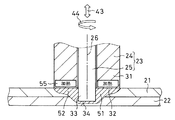
図1は、本発明の実施の一形態の接合動作を示す断面図である。上下に重ねられた複数たとえば2つの被接合物21,22は、本発明に従う摩擦撹拌接合治具23を備える摩擦撹拌装置によって接合される。この治具23は、治具本体24と、治具本体24を挿通する軸部25とを含む。治具本体24は、直円筒状であり、その軸線26と同軸に挿通孔27が形成される。軸部25は、この挿通孔27を、軸線26と同軸に配置される。軸部25は、直円柱状である。治具本体24の端部31の端面32は、軸線26に垂直である。軸部25の端部33の端面34も、軸線26に垂直である。軸部25は、治具本体24に没入および突出可能に形成される。なお軸部25は、被接合物21,22を加圧および回転摩擦熱を与えることができる形状であればよく、直円柱状以外の形状、たとえば先端に進むにつれて縮経する円錐形状であってもよい。
【0025】
図2は、図1に示される摩擦撹拌接合治具23を用いる摩擦撹拌接合装置35の簡略化した断面図である。被接合物21,22は、定盤36上に乗載されて固定される。この状態に固定的に設けられる装置本体37には、治具本体24の端部31を被接合物21,22に加圧する治具本体用加圧手段41と、治具本体24を、その軸線26まわりに回転駆動する治具本体用回転駆動手段42と、軸部25の端部33を被接合物21,22に加圧する軸部用加圧手段43と、軸部25をその軸線26まわりに回転駆動する軸部用回転駆動手段44とを含む。これらの各手段41〜44は、たとえばサーボモータを含んで構成される。検出手段46は、治具23による被接合物21,22の接合状態を検出する。検出手段26は、たとえば光学式センサまたはテレビカメラなどによって実現されてもよい。図2に示す摩擦撹拌接合装置35は、本発明の例示に過ぎず、多関節ロボットたとえば6軸多関節ロボットの手首に摩擦撹拌接合装置を装着してもよい。
【0026】
図3は、図2に示される摩擦撹拌接合装置35の電気的構成を示すブロック図である。マイクロコンピュータなどによって実現される処理回路47は検出手段46の出力に応答し、前述の各手段41〜44の動作を制御する。検出手段46は、各手段41〜44にそれぞれ含まれているモータの負荷電流を検出して接合状態を検出する構成を有してもよい。
【0027】
図4は図1(1)〜図1(5)に示される摩擦撹拌接合装置35の動作を説明するためのタイミングチャートであり、図5は図3に示される処理回路47の動作を説明するためのフローチャートである。処理回路47は、摩擦撹拌接合装置35の表1に示される動作モードを順次的に達成する。
【0028】
【表1】

摩擦撹拌接合治具23の治具本体24は、治具本体用加圧手段41によって、図4(A)に示されるように下降および上昇移動され、治具本体用回転駆動手段42によって図4(C)に示されるように回転駆動される。治具本体を加圧手段41によって治具本体24に作用する加圧力は、図4(E)に示される。
【0030】
軸部25は、軸部用加圧手段43によって図4(B)に示されるように下降および上昇移動され、軸部用回転駆動手段44によって図4(D)に示されるように回転駆動される。この軸部25に作用する加圧力は、図4(F)に示される。
【0031】
処理回路47は、図5のステップa1では、摩擦撹拌治具23は、第1動作モードに移行した状態であり、図1(1)に示されるように、前述の各手段41〜44が停止している。処理回路47は、外部から摩擦撹拌接合命令が与えられると、摩擦撹拌治具23を接合位置上方に配置し、ステップa2に進む。
【0032】
ステップa2では、時刻t1以降、処理回路部47は、摩擦撹拌治具23を第2動作モードに移行させ、治具本体用加圧手段41によって、治具本体24を下降させる。次に、時刻t1から時刻t2に達すると、摩擦撹拌治具23を第3動作モードに移行させ、軸部用加圧手段43によって、軸部25を下降させる。
【0033】
処理回路部47は、時刻t2から時刻t3に達すると、摩擦撹拌治具を第4動作モードに移行させ、軸部用回転駆動手段44によって、軸部25を回転駆動させる。治具本体24および軸部25が下降し、治具本体24の端面32が被接合物21に接触したことが検出されると、ステップa3に進む。
【0034】
ステップa3では、図1(2)に示されるように、治具本体24の端面32が被接合物21に接触する。時刻t3から時刻t4に達すると、処理回路部47は、摩擦撹拌治具23を第5動作モードに移行させ、治具本体用加圧手段41によって、治具本体24を被接合物21に予備加圧力P1で予備加圧する。予備加圧を行うことによって、被接合物21,22間の隙間が解消され、被接合物21,22が密着する。被接合物21,22が密着すると、ステップa4に進む。
【0035】
ステップa4では、時刻t4から時刻t5に達すると、軸部25が被接合物21に接触し、処理回路部27は、摩擦撹拌治具23を第6動作モードに移行させる。第6動作モードでは、軸部用加圧手段43によって、軸部25を被接合物21に加圧力P2で回転加圧する。これによって図1(3)に示されるように、軸部25と被接合物21とによって摩擦熱が生じ、軸部25付近の被接合物21が軟化し、軸部25が被接合物21に食い込む。
【0036】
時刻t5から時刻t6に達すると、処理回路部27は、摩擦撹拌治具23を第7動作モードに移行させる。第7動作モードでは、治具本体用加圧手段41によって、治具本体24を予備加圧力P1より大きい加圧力3で加圧する。これによって図1(4)に示されるように、治具本体24と被接合物21とによって摩擦熱が生じ、治具本体24付近の被接合物21が軟化し、治具本体24が被接合物に食い込み、被接合物21,22が部分的に摩擦撹拌状態となる。
【0037】
このとき、治具本体24と軸部25とは、各回転駆動手段42,43によって回転駆動され、各加圧手段41,43によって、被接合物21,22を加圧する。治具本体24および軸部25は、それぞれ摩擦撹拌接合が最適に行われる回転速度および加圧力に設定される。
【0038】
軸部25は、被接合物21,22の軟化部分を撹拌するのに十分な加圧力および回転速度に設定され、治具本体24は、被接合物を軟化するとともに、軟化部分の撹拌が小さい加圧力および回転速度に設定される。
【0039】
たとえば治具本体24の治具本体用回転駆動手段42による回転速度V1に比べて、軸部25の軸部用回転駆動手段44による回転速度V2は、高い値に設定される。すなわちV1<V2に設定される。また治具本体24と軸部25とが各加圧手段41,43によって加圧され、治具本体24の治具本体用加圧手段41による加圧力P3に比べて、軸部25の軸部用加圧手段43による加圧力P2は大きい値に設定される。すなわちP3<P2に設定される。
【0040】
摩擦撹拌状態で予め定められた摩擦撹拌時間Wが経過するとステップa5に進む。
【0041】
ステップa5では、摩擦撹拌時間Wが経過し時刻t6から時刻t7に達すると、2つの被接合物21,22が軟化撹拌されて接合部分が形成され、処理回路部27は、摩擦撹拌治具23を第8動作モードに移行させる。第8動作モードでは、各加圧手段41,43によって治具本体24および軸部25が回転状態を保ったまま上昇される。
【0042】
時刻t7から時刻t8に達すると、処理回路部27は、摩擦撹拌治具23を第9動作モードに移行させる。第9動作モードでは、治具本体用回転駆動手段42によって治具本体24の回転を停止する。
【0043】
時刻t8から時刻t9に達すると、処理回路部27は、摩擦撹拌治具23を第10動作モードに移行させる。第10動作モードでは、各転駆動手段42,44によって治具本体25および軸部25の回転を停止し、ステップa6に進む。ステップa6では、図1(5)に示されるように、摩擦撹拌治具23が被接合物の接合位置より上方の位置に配置され一連の動作を終了する。
【0044】
摩擦撹拌治具は、ステップa3で治具本体24によって被接合物を予備加圧することによって、被接合物21,22間の隙間を解消した状態で摩擦撹拌動作を行う。これによって接合不良を生じることなく良好な摩擦撹拌接合を行うことができる。また治具本体24と、軸部25との回転速度および加圧力を個別に制御することができるので、治具本体24には、被接合物21,22を軟化させるのに適した回転速度および加圧力に設定し、軸部25には、被接合物21,22の軟化部分を撹拌させるのに適した回転速度および加圧力に設定することができる。これによって接合部分の領域を広範囲に形成することができ、接合強度を向上させることができる。また治具本体24と軸部25との回転方向は互いに同一方向であっても、逆方向であってもよく、さらに接合中に回転方向が反転してもよい。治具本体24および軸部25の回転方向は、摩擦撹拌接合が良好に行われる回転方向にそれぞれ個々に設定することができる。
【0045】
またたとえば治具本体24の前記端部が被接合物21,22を押圧して入り込む変位量ΔL1を、軸部用加圧手段43によって軸部25の前記端部55が被接合物を押圧して入り込む変位量ΔL2未満となる値すなわちΔL1<ΔL2となるように、治具本体24と軸部25との回転速度および加圧力を調整することによって、治具本体24が被接合物21に入り込む量を小さくして、剪断強度などの接合強度を向上することができるとともに、前述の先行技術に関連して述べた隆起部の発生を、抑制することができ、接合品質を向上することができる。たとえば治具本体24の変位量ΔL1は、最初に治具本体24が接触する被接合物21の厚みの被接合物21の厚みの10%以下に設定される。被接合物の疲労強度は、前記変位量ΔL1が大きくなるにつれて低下するため、変位量ΔL1は、必要とされる被接合物の強度に応じて、必要最小限の変位量が適宜設定される。
【0046】
図6は、被接合物21,22の隙間を解消した状態で摩擦撹拌接合された被接合物21,22の拡大断面図である。被接合物21,22は、比較的広い接合領域48,49にわたって接合されており、それらの接合部分51,52の厚みΔd2は、充分に厚く、しかも隆起部53は、ごくわずかとなる。本発明にしたがう摩擦撹拌接合でも被接合物21,22の隙間を解消した状態で接合することができる。したがって図6と同様な接合状態を得ることができ、被接合物21,22を広い接合領域48,49にわたって接合して、摩擦撹拌接合強度を充分に大きくすることができる。
【0047】
上述の形態では、第4〜第6動作モードにおいて、治具本体24は回転せずに停止した状態であるが、本発明の実施の他の形態として第4〜第6動作モードにおいて、治具本体24は治具本体用回転駆動手段42によって低速度V3で回転駆動されたままであってもよい。この低い回転速度V3は、軸部25の加圧回転の時刻t2以降における前述の速度V1未満である(V3<V1)。このような実施の形態においてもまた、治具本体24は、前述の低い回転速度V3で被接合物21,22に接触し、加圧するので、高い精度で、正確な位置に接合を行うことができる。
【0048】
図7は、本発明の実施の他の形態の一部の断面図である。この実施の形態は、前述の実施の形態に類似し、対応する部分には同一の参照符を付す。注目すべきはこの実施の形態では、摩擦撹拌接合治具23の治具本体24の下部31に、加熱手段55が内蔵される。加熱手段55は、たとえば電気ヒータであってもよく、あるいはまた交流電源から電力が供給される誘導加熱コイルであってもよい。図7に示される実施の形態では、治具本体24を昇降移動して加圧する治具本体用加圧手段41が設けられるが、治具本体用回転駆動手段40には設けられず、この治具本体24は回転しない。軸部25は、軸部用加圧手段43によって昇降移動、加圧し、また軸部用回転駆動手段44によって回転駆動される。加熱手段55は、被接合物21,22を、軟化することができる温度に加熱し、この軟化部分を、軸部25の加圧、回転駆動によって、撹拌する。
【0049】
図7に示される実施の形態では、前述のように治具本体24が回転されず、停止されたままであるので、その端部31の端面32が被接合物21に食い込むことはなく、被接合物21,22に入り込まない。したがって前述の先行技術に関連して述べたように、被接合物21の接合領域における厚みが減少することはなく、剪断強度などの接合強度が高く達成される。
【0050】
図8は、本発明の摩擦撹拌接合装置35が、ロボット57の手首58に装着された状態を示す簡略化した側面図である。ロボット57は、複数軸を有し、予め教示した教示内容を、メモリから読出し、再生動作を行い、スポット接合を自動的に行うことができ、さらにまた摩擦撹拌接合装置35を予め定める接合線に沿って移動して接合動作を行うこともできる。また上述した記載において、治具本体24および軸部25が上昇および下降するとしたが、押圧方向に変位すればよく、水平方向に並ぶ2つの被接合物を接合してもよく、それ以外の方向でも接合可能である。
【0051】
【発明の効果】
以上のように本発明によれば、治具本体と軸部とを加圧と回転駆動とを個別に動作することによって、母材である被接合物への食い込み量を、治具本体と軸部とに関して個別的に設定することができ、したがって剪断強度などの接合強度の向上を図ることができるとともに、各種の厚みを有する被接合物に共通な摩擦撹拌接合治具を用いることができ、作業性が良好であり、さらに前述の図10に関連して述べた隆起部13の発生を抑制し、その隆起部の材料分、接合強度の向上を図ることができる。
【0052】
また本発明によれば、摩擦撹拌接合治具の治具本体は、回転が停止している状態で、治具本体によって被接合物を押圧するので、スポット接合の接合位置を高精度で設定することができる。また被接合物間のギャップを解消することができ、確実な接合を行うことができる。
【0053】
また本発明によれば、治具本体の回転による摩擦熱によって被接合物を軟化させる場合、治具本体の端部が被接合物に入り込む変位量ΔL1を、小さくすることによって、接合される被接合物の剪断強度などの接合強度を向上することができるとともに、前記隆起部の発生を抑制することができ、接合品質を向上することができる。
【0055】
また本発明によれば、スポット接合を行うことによって、接合部分の接合強度を向上することができ、良好な接合品質を得ることができる。
【図面の簡単な説明】
【図1】本発明の実施の一形態の接合動作を示す断面図である。
【図2】図1に示される摩擦撹拌接合治具23を用いる摩擦撹拌接合装置35の簡略化した断面図である。
【図3】図2に示される摩擦撹拌接合装置35の電気的構成を示すブロック図である。
【図4】図1(1)〜図1(5)に示される摩擦撹拌接合装置35の動作を説明するためのタイミングチャートである。
【図5】図3に示される処理回路47の動作を説明するためのフローチャートである。
【図6】被接合物21,22の隙間を解消した状態で摩擦撹拌接合された被接合物21,22の拡大断面図である。
【図7】本発明の実施の他の形態の一部の断面図である。
【図8】本発明の摩擦撹拌接合装置35が、ロボット57の手首58に装着された状態を示す簡略化した側面図である。
【図9】先行技術の摩擦撹拌接合装置1の一部の断面図である。
【図10】図9に示される先行技術の回転子2を用いて摩擦撹拌接合された被接合物3,4の拡大断面図である。
【符号の説明】
21,22 被接合物
23 摩擦撹拌接合治具
24 治具本体
25 軸部
26 軸線
27 挿通孔
31,33 端部
32,34 端面
35 摩擦撹拌接合装置
41 治具本体用加圧手段
42 治具本体用回転駆動手段
43 軸部用加圧手段
44 軸部用回転駆動手段
55 加熱手段[0001]
BACKGROUND OF THE INVENTION
The present invention relates to a friction stir welding apparatus that performs an object to be joined, such as spot welding, by friction stir welding.
[0002]
[Prior art]
FIG. 9 is a partial cross-sectional view of the prior art friction
[0003]
FIG. 10 is an enlarged cross-sectional view of the
[0004]
As the
[0005]
Since the
[0006]
Moreover, since the
[0007]
[Problems to be solved by the invention]
An object of the present invention is to improve joint strength such as shear strength, and can use a common friction stir welding jig regardless of the objects to be joined having various thicknesses. to provide a friction stir welding equipment that allow.
[0008]
[Means for Solving the Problems]
The present invention is a friction stir welding jig,
A jig main body having an end for pressing the object to be joined, and having an insertion hole coaxial with the axis;
A friction stir welding jig including a shaft portion that is inserted into the insertion hole and is provided so as to be displaceable in the axial direction and has an end portion that can project from the end portion of the jig body;
Pressurizing means for a jig body that pressurizes the end of the jig body against an object to be joined;
Rotation driving means for jig body for rotating the jig body;
A pressurizing unit for the shaft that pressurizes the end of the shaft to the workpiece;
A rotation driving means for a shaft for rotating the shaft;
A jig main body pressing means, a jig main body rotation driving means, a shaft portion pressing means, and a shaft portion rotation driving means for individually controlling,
The control means starts rotating the jig body by the jig body rotation driving means in a state where the end of the jig body is pressurized to the object to be joined by the jig body pressing means,
In the pressurizing state of the jig main body, the shaft portion is rotationally driven by the shaft portion rotation driving means while the end portion of the shaft portion is pressed against the workpiece by the shaft portion pressing means. It is a friction stir welding apparatus .
[0010]
According to the present invention, the friction stir welding jig includes a jig main body and a shaft portion coaxially inserted through the insertion hole of the jig main body, and the jig main body and the shaft portion are for the jig main body. It operates by each means of pressurization and rotation drive, and the shaft part operates by each means of pressurization and rotation drive for the shaft part. Therefore, pressurization and rotational driving of the jig main body and the shaft portion can be individually controlled. Therefore, the amount of biting into the workpiece, which is the base material, can be individually set for the jig body and the shaft portion, so that it is possible to improve the bonding strength such as shear strength and various thicknesses. Friction stir welding jigs common to objects to be joined can be used, workability is good, and the occurrence of the raised
[0013]
According to the present invention, the jig body of the friction stir joining jig in a state where rotation is stopped, stop the pressurized by pressing the object to be bonded, thus jig body is the rotation by the jig body retaining In a state where the pressure is applied , the shaft portion is rotationally driven while being pressurized. Therefore, the object to be joined is pressurized by the jig body, and the joining position, particularly the joining position during spot joining can be set with high accuracy. Further, when joining two overlapping objects to be bonded, the gap between the objects to be bonded can be eliminated over a wide range by pressing the objects to be bonded with a jig body having an area larger than the shaft portion. Reliable joining can be performed.
[0014]
The present invention, the control means, the displacement amount ΔL1 that said end of the jig body enters pressurizes the objects to be bonded by the pressurizing means for the jig body,
The shaft portion pressurizing means controls the end portion of the shaft portion so as to have a value smaller than a displacement amount ΔL2 that presses and enters the workpiece.
[0015]
According to the present invention, the displacement amount ΔL1 at which the end portion of the jig body enters the workpiece is independent of the displacement amount ΔL2 at which the end portion of the shaft portion enters the workpiece. Therefore, by reducing the displacement amount ΔL1 of the jig main body, it is possible to improve the joining strength such as the shear strength and to describe it in relation to the above-mentioned prior art. Occurrence of the raised portions can be suppressed, and the bonding quality can be improved.
[0022]
Moreover, the present invention is an apparatus for performing spot bonding .
[0023]
According to the present invention, by performing spot bonding with the above-described apparatus or jig, the bonding strength of the bonded portion can be improved, and good bonding quality can be obtained.
[0024]
DETAILED DESCRIPTION OF THE INVENTION
FIG. 1 is a cross-sectional view showing a bonding operation according to an embodiment of the present invention. A plurality of, for example, two
[0025]
FIG. 2 is a simplified cross-sectional view of a friction
[0026]
FIG. 3 is a block diagram showing an electrical configuration of the friction
[0027]
FIG. 4 is a timing chart for explaining the operation of the friction
[0028]
[Table 1]
The jig
[0030]
The
[0031]
In step a1 of FIG. 5, the
[0032]
In step a2, after time t1, the
[0033]
When the
[0034]
In step a3, as shown in FIG. 1 (2), the
[0035]
In step a4, when the time t4 is reached from the time t4, the
[0036]
When reaching the time t6 from the time t5, the
[0037]
At this time, the jig
[0038]
The
[0039]
For example, the rotation speed V2 of the
[0040]
When a predetermined friction stirring time W elapses in the friction stirring state, the process proceeds to step a5.
[0041]
In step a5, when the friction agitation time W elapses and time t6 reaches time t7, the two
[0042]
When reaching time t8 from time t7, the
[0043]
When reaching time t9 from time t8, the
[0044]
The friction stirrer performs a friction stir operation in a state in which the gap between the
[0045]
Further, for example, the displacement amount ΔL1 in which the end portion of the
[0046]
FIG. 6 is an enlarged cross-sectional view of the
[0047]
In the above-described embodiment, the
[0048]
FIG. 7 is a partial cross-sectional view of another embodiment of the present invention. This embodiment is similar to the above-described embodiment, and corresponding portions are denoted by the same reference numerals. It should be noted that in this embodiment, the heating means 55 is built in the
[0049]
In the embodiment shown in FIG. 7, the
[0050]
FIG. 8 is a simplified side view showing a state in which the friction
[0051]
【The invention's effect】
As described above, according to the present invention, by pressing and rotating the jig main body and the shaft part separately, the amount of biting into the workpiece to be joined can be reduced. It can be set individually with respect to the part, so that it is possible to improve the joint strength such as shear strength, and a friction stir welding jig common to the workpieces having various thicknesses can be used, The workability is good, and further, the occurrence of the raised
[0052]
Further, according to the present invention, the jig main body of the friction stir welding jig presses the object to be joined by the jig main body in a state where the rotation is stopped. be able to. Further, the gap between the objects to be bonded can be eliminated, and reliable bonding can be performed.
[0053]
According to the present invention, when the workpiece is softened by frictional heat generated by the rotation of the jig main body, the displacement ΔL1 at which the end of the jig main body enters the workpiece is reduced, thereby reducing the workpiece to be joined. While joining strength, such as the shear strength of a joined material, can be improved, generation | occurrence | production of the said protruding part can be suppressed and joining quality can be improved.
[0055]
Further, according to the present invention, by performing spot bonding, it is possible to improve the bonding strength of the bonded portion and to obtain good bonding quality.
[Brief description of the drawings]
FIG. 1 is a cross-sectional view showing a bonding operation according to an embodiment of the present invention.
2 is a simplified cross-sectional view of a friction
FIG. 3 is a block diagram showing an electrical configuration of the friction
4 is a timing chart for explaining the operation of the friction
FIG. 5 is a flowchart for explaining the operation of the
FIG. 6 is an enlarged cross-sectional view of the
FIG. 7 is a partial cross-sectional view of another embodiment of the present invention.
8 is a simplified side view showing a state in which the friction
FIG. 9 is a partial cross-sectional view of the prior art friction
FIG. 10 is an enlarged cross-sectional view of
[Explanation of symbols]
21, 22
Claims (3)
被接合物を押圧する端部を有し、軸線と同軸の挿通孔が形成される治具本体と、
挿通孔に挿通され、前記軸線方向に変位自在に設けられ、治具本体の前記端部から突出可能な端部を有する軸部とを含む摩擦撹拌接合治具と、
治具本体の前記端部を被接合物に加圧する治具本体用加圧手段と、
治具本体を回転駆動する治具本体用回転駆動手段と、
軸部の前記端部を被接合物に加圧する軸部用加圧手段と、
軸部を回転駆動する軸部用回転駆動手段と、
治具本体用加圧手段と治具本体用回転駆動手段と軸部用加圧手段と軸部用回転駆動手段とを個別的に制御する制御手段とを含み、
制御手段は、治具本体用加圧手段によって治具本体の前記端部を被接合物に加圧した状態で、治具本体用回転駆動手段によって治具本体の回転駆動を開始し、
治具本体の前記加圧状態で、軸部用加圧手段によって軸部の前記端部を被接合物に加圧しつつ、軸部用回転駆動手段によって軸部を回転駆動することを特徴とする摩擦撹拌接合装置。A friction stir welding jig,
A jig main body having an end for pressing the object to be joined, and having an insertion hole coaxial with the axis;
A friction stir welding jig including a shaft portion that is inserted into the insertion hole and is provided so as to be displaceable in the axial direction and has an end portion that can project from the end portion of the jig body;
Pressurizing means for a jig body that pressurizes the end of the jig body against an object to be joined;
Rotation driving means for jig body for rotating the jig body;
A pressurizing unit for the shaft that pressurizes the end of the shaft to the workpiece;
A rotation driving means for a shaft for rotating the shaft;
A jig main body pressing means, a jig main body rotation driving means, a shaft portion pressing means, and a shaft portion rotation driving means for individually controlling,
The control means starts rotating the jig body by the jig body rotation driving means in a state where the end of the jig body is pressurized to the object to be joined by the jig body pressing means,
In the pressurizing state of the jig main body, the shaft portion is rotationally driven by the shaft portion rotation driving means while the end portion of the shaft portion is pressed against the workpiece by the shaft portion pressing means. Friction stir welding device.
軸部用加圧手段によって軸部の前記端部が被接合物を押圧して入り込む変位量ΔL2よりも小さい値となるように制御することを特徴とする請求項1記載の摩擦撹拌接合装置。 The control means has a displacement amount ΔL1 in which the end of the jig body pressurizes the object to be joined by the jig body pressurizing means,
Friction stir welding apparatus according to claim 1, wherein said end portion of the shaft portion by pressing means for the shaft portion is characterized that you controlled so that a value smaller than the displacement amount ΔL2 enter by pressing the object to be bonded .
Priority Applications (1)
| Application Number | Priority Date | Filing Date | Title |
|---|---|---|---|
| JP2002111084A JP4183964B2 (en) | 2002-04-12 | 2002-04-12 | Friction stir welding equipment |
Applications Claiming Priority (1)
| Application Number | Priority Date | Filing Date | Title |
|---|---|---|---|
| JP2002111084A JP4183964B2 (en) | 2002-04-12 | 2002-04-12 | Friction stir welding equipment |
Related Child Applications (1)
| Application Number | Title | Priority Date | Filing Date |
|---|---|---|---|
| JP2008163883A Division JP4740289B2 (en) | 2008-06-23 | 2008-06-23 | Friction stir welding equipment |
Publications (3)
| Publication Number | Publication Date |
|---|---|
| JP2003305576A JP2003305576A (en) | 2003-10-28 |
| JP2003305576A5 JP2003305576A5 (en) | 2005-09-22 |
| JP4183964B2 true JP4183964B2 (en) | 2008-11-19 |
Family
ID=29394029
Family Applications (1)
| Application Number | Title | Priority Date | Filing Date |
|---|---|---|---|
| JP2002111084A Expired - Fee Related JP4183964B2 (en) | 2002-04-12 | 2002-04-12 | Friction stir welding equipment |
Country Status (1)
| Country | Link |
|---|---|
| JP (1) | JP4183964B2 (en) |
Cited By (1)
| Publication number | Priority date | Publication date | Assignee | Title |
|---|---|---|---|---|
| CN101498259B (en) * | 2009-01-24 | 2011-01-05 | 哈尔滨市三棵树铁路客车配件有限公司 | Diesel self-heating apparatus of railway air conditioning generator car lower fuel tank |
Families Citing this family (20)
| Publication number | Priority date | Publication date | Assignee | Title |
|---|---|---|---|---|
| JP4148152B2 (en) * | 2004-02-16 | 2008-09-10 | マツダ株式会社 | Friction spot joint structure |
| JP4537132B2 (en) * | 2004-07-07 | 2010-09-01 | 川崎重工業株式会社 | Friction stir welding method for spot welding |
| JP4517760B2 (en) * | 2004-07-29 | 2010-08-04 | マツダ株式会社 | Friction spot welding method and apparatus |
| JP4491782B2 (en) * | 2004-09-30 | 2010-06-30 | マツダ株式会社 | Friction welding method and friction welding apparatus |
| JP4754256B2 (en) | 2005-04-19 | 2011-08-24 | 住友軽金属工業株式会社 | Rotating tool for friction stir spot welding and friction stir spot joining method using the same |
| DE102005019758B4 (en) * | 2005-04-28 | 2007-12-13 | Hydro Aluminium Deutschland Gmbh | Method and apparatus for joining at least two components made of dissimilar materials |
| JP4672434B2 (en) * | 2005-05-18 | 2011-04-20 | 住友軽金属工業株式会社 | Friction stir spot welding method |
| JP4619875B2 (en) * | 2005-06-21 | 2011-01-26 | 住友軽金属工業株式会社 | Friction stir spot welding method |
| DE102005029882A1 (en) * | 2005-06-27 | 2006-12-28 | Gkss-Forschungszentrum Geesthacht Gmbh | Friction stir welding apparatus includes first inner segment surrounding a pin and having first friction surface segment surrounding the first inner segment and rotationally driven independently of the first inner segment |
| JP4690812B2 (en) * | 2005-07-29 | 2011-06-01 | 住友軽金属工業株式会社 | Friction stir spot welding method |
| JP4628218B2 (en) * | 2005-08-22 | 2011-02-09 | Obara株式会社 | Friction stir spot welding equipment |
| DE102005060178B4 (en) * | 2005-12-14 | 2010-04-15 | Eads Deutschland Gmbh | Friction stir tool with conformable shoulder and its use |
| US7581665B2 (en) | 2006-01-04 | 2009-09-01 | The Boeing Company | Methods and apparatus for retractable pin friction stir welding and spot welding |
| JP4853864B2 (en) * | 2006-02-20 | 2012-01-11 | Obara Group株式会社 | Cleaning method of FSW joint tool |
| JP4853865B2 (en) * | 2006-02-20 | 2012-01-11 | Obara Group株式会社 | Cleaning method of FSW joint tool |
| US7691218B2 (en) * | 2006-09-06 | 2010-04-06 | Brady Worldwide, Inc. | Method of attaching a label to a thermoplastic substrate |
| WO2008082420A1 (en) * | 2007-01-05 | 2008-07-10 | The Boeing Company | Methods and apparatus for retractable pin friction stir welding and spot welding |
| JP4937386B2 (en) * | 2010-07-22 | 2012-05-23 | 住友軽金属工業株式会社 | Dissimilar metal member joining method |
| JP6307005B2 (en) * | 2014-10-23 | 2018-04-04 | 川崎重工業株式会社 | Evaluation method of joining state in friction stir spot welding, and friction stir spot welding apparatus using this evaluation method |
| CN105108316A (en) * | 2015-09-15 | 2015-12-02 | 昆山斯格威电子科技有限公司 | Accumulated chipping removing device of stir friction spot welding apparatus |
-
2002
- 2002-04-12 JP JP2002111084A patent/JP4183964B2/en not_active Expired - Fee Related
Cited By (1)
| Publication number | Priority date | Publication date | Assignee | Title |
|---|---|---|---|---|
| CN101498259B (en) * | 2009-01-24 | 2011-01-05 | 哈尔滨市三棵树铁路客车配件有限公司 | Diesel self-heating apparatus of railway air conditioning generator car lower fuel tank |
Also Published As
| Publication number | Publication date |
|---|---|
| JP2003305576A (en) | 2003-10-28 |
Similar Documents
| Publication | Publication Date | Title |
|---|---|---|
| JP4183964B2 (en) | Friction stir welding equipment | |
| JP5022502B2 (en) | Friction stir welding equipment | |
| US6601751B2 (en) | Method and apparatus for joining | |
| JP4740289B2 (en) | Friction stir welding equipment | |
| JP2004141898A (en) | Friction stirring and joining method and device | |
| JP4050478B2 (en) | Processing control method using friction stirring, computer program for executing the method, and storage medium storing the computer program | |
| JP3516913B2 (en) | Spot joining apparatus and spot joining method | |
| JP2004148320A (en) | Method and tool for friction stir welding joint | |
| WO2015146185A1 (en) | Friction stir welding device and friction stir welding method | |
| JP2003205374A (en) | Spot welding system and fixing device | |
| JP3546043B2 (en) | Friction stir welding method and apparatus | |
| JP4346887B2 (en) | Welding tool, friction stir welding apparatus, and friction stir welding method | |
| JP3911232B2 (en) | Friction stir welding equipment | |
| JP3859582B2 (en) | Friction stir welding apparatus and friction stir welding method | |
| US11858060B2 (en) | Friction stir spot welding device and method for operating same | |
| JP2004174507A (en) | Friction stir welding device, and friction stir welding method | |
| JP4172343B2 (en) | Friction spot welding method | |
| JP2003112271A (en) | Friction stirr welding method | |
| KR102524024B1 (en) | Friction element welding apparatus and method thereof | |
| JP4594882B2 (en) | Friction stir welding apparatus and friction stir welding method | |
| JP2004202536A (en) | Friction stir welding apparatus and method using bobbin tool | |
| JP2002292480A (en) | Bonding method and apparatus using friction and agitation | |
| JP4517760B2 (en) | Friction spot welding method and apparatus | |
| KR100765843B1 (en) | A joining method for a aluminum panel | |
| JP4661367B2 (en) | Friction spot welding method and apparatus |
Legal Events
| Date | Code | Title | Description |
|---|---|---|---|
| A521 | Written amendment |
Free format text: JAPANESE INTERMEDIATE CODE: A523 Effective date: 20050411 |
|
| A621 | Written request for application examination |
Free format text: JAPANESE INTERMEDIATE CODE: A621 Effective date: 20050411 |
|
| A977 | Report on retrieval |
Free format text: JAPANESE INTERMEDIATE CODE: A971007 Effective date: 20080417 |
|
| A131 | Notification of reasons for refusal |
Free format text: JAPANESE INTERMEDIATE CODE: A131 Effective date: 20080422 |
|
| A521 | Written amendment |
Free format text: JAPANESE INTERMEDIATE CODE: A523 Effective date: 20080623 |
|
| TRDD | Decision of grant or rejection written | ||
| A01 | Written decision to grant a patent or to grant a registration (utility model) |
Free format text: JAPANESE INTERMEDIATE CODE: A01 Effective date: 20080902 |
|
| A01 | Written decision to grant a patent or to grant a registration (utility model) |
Free format text: JAPANESE INTERMEDIATE CODE: A01 |
|
| A61 | First payment of annual fees (during grant procedure) |
Free format text: JAPANESE INTERMEDIATE CODE: A61 Effective date: 20080903 |
|
| FPAY | Renewal fee payment (event date is renewal date of database) |
Free format text: PAYMENT UNTIL: 20110912 Year of fee payment: 3 |
|
| R150 | Certificate of patent or registration of utility model |
Free format text: JAPANESE INTERMEDIATE CODE: R150 Ref document number: 4183964 Country of ref document: JP Free format text: JAPANESE INTERMEDIATE CODE: R150 |
|
| FPAY | Renewal fee payment (event date is renewal date of database) |
Free format text: PAYMENT UNTIL: 20110912 Year of fee payment: 3 |
|
| FPAY | Renewal fee payment (event date is renewal date of database) |
Free format text: PAYMENT UNTIL: 20120912 Year of fee payment: 4 |
|
| FPAY | Renewal fee payment (event date is renewal date of database) |
Free format text: PAYMENT UNTIL: 20120912 Year of fee payment: 4 |
|
| FPAY | Renewal fee payment (event date is renewal date of database) |
Free format text: PAYMENT UNTIL: 20130912 Year of fee payment: 5 |
|
| FPAY | Renewal fee payment (event date is renewal date of database) |
Free format text: PAYMENT UNTIL: 20140912 Year of fee payment: 6 |
|
| LAPS | Cancellation because of no payment of annual fees |