JP2004148320A - Method and tool for friction stir welding joint - Google Patents
Method and tool for friction stir welding joint Download PDFInfo
- Publication number
- JP2004148320A JP2004148320A JP2002313019A JP2002313019A JP2004148320A JP 2004148320 A JP2004148320 A JP 2004148320A JP 2002313019 A JP2002313019 A JP 2002313019A JP 2002313019 A JP2002313019 A JP 2002313019A JP 2004148320 A JP2004148320 A JP 2004148320A
- Authority
- JP
- Japan
- Prior art keywords
- work
- hole
- tool
- joining
- plate
- Prior art date
- Legal status (The legal status is an assumption and is not a legal conclusion. Google has not performed a legal analysis and makes no representation as to the accuracy of the status listed.)
- Granted
Links
Images


Classifications
-
- B—PERFORMING OPERATIONS; TRANSPORTING
- B23—MACHINE TOOLS; METAL-WORKING NOT OTHERWISE PROVIDED FOR
- B23K—SOLDERING OR UNSOLDERING; WELDING; CLADDING OR PLATING BY SOLDERING OR WELDING; CUTTING BY APPLYING HEAT LOCALLY, e.g. FLAME CUTTING; WORKING BY LASER BEAM
- B23K20/00—Non-electric welding by applying impact or other pressure, with or without the application of heat, e.g. cladding or plating
- B23K20/22—Non-electric welding by applying impact or other pressure, with or without the application of heat, e.g. cladding or plating taking account of the properties of the materials to be welded
- B23K20/227—Non-electric welding by applying impact or other pressure, with or without the application of heat, e.g. cladding or plating taking account of the properties of the materials to be welded with ferrous layer
- B23K20/2275—Non-electric welding by applying impact or other pressure, with or without the application of heat, e.g. cladding or plating taking account of the properties of the materials to be welded with ferrous layer the other layer being aluminium
-
- B—PERFORMING OPERATIONS; TRANSPORTING
- B23—MACHINE TOOLS; METAL-WORKING NOT OTHERWISE PROVIDED FOR
- B23K—SOLDERING OR UNSOLDERING; WELDING; CLADDING OR PLATING BY SOLDERING OR WELDING; CUTTING BY APPLYING HEAT LOCALLY, e.g. FLAME CUTTING; WORKING BY LASER BEAM
- B23K20/00—Non-electric welding by applying impact or other pressure, with or without the application of heat, e.g. cladding or plating
- B23K20/12—Non-electric welding by applying impact or other pressure, with or without the application of heat, e.g. cladding or plating the heat being generated by friction; Friction welding
- B23K20/122—Non-electric welding by applying impact or other pressure, with or without the application of heat, e.g. cladding or plating the heat being generated by friction; Friction welding using a non-consumable tool, e.g. friction stir welding
- B23K20/1245—Non-electric welding by applying impact or other pressure, with or without the application of heat, e.g. cladding or plating the heat being generated by friction; Friction welding using a non-consumable tool, e.g. friction stir welding characterised by the apparatus
- B23K20/1255—Tools therefor, e.g. characterised by the shape of the probe
-
- B—PERFORMING OPERATIONS; TRANSPORTING
- B23—MACHINE TOOLS; METAL-WORKING NOT OTHERWISE PROVIDED FOR
- B23K—SOLDERING OR UNSOLDERING; WELDING; CLADDING OR PLATING BY SOLDERING OR WELDING; CUTTING BY APPLYING HEAT LOCALLY, e.g. FLAME CUTTING; WORKING BY LASER BEAM
- B23K33/00—Specially-profiled edge portions of workpieces for making soldering or welding connections; Filling the seams formed thereby
Abstract
Description
【0001】
【発明の属する技術分野】
本発明は、摩擦撹拌を用いた接合方法、及びその方法に使用する接合用工具に関する。
【0002】
【従来の技術】
摩擦撹拌を用いた接合方法として、特許文献1に示すように、重ねられた板状のワークのうち、該ワークの重ね方向一方側における一方のワークに対して回転ツールを当接させて、該重ねられたワークに対して、該ワークの重ね方向に向けて加圧力を付与すると共に該加圧力の加圧方向を中心として回転力を付与するものがある。このものによれば、回転ツールの加圧と回転とに伴い、回転ツールと重ねられたワークとの間で発生される摩擦熱によりそのワークが軟化されて、そのワーク内に回転ツールが進入される。このため、その回転ツールによりワーク内における重ね面付近で塑性流動が引き起こされることになり、重ねられたワークは、その重ね面付近でスポット的に一体化することになる。
【0003】
【特許文献1】
特開2001−314982号公報
【0004】
【発明が解決しようとする課題】
しかし、上記接合方法においては、回転ツールによって一方のワークを他方のワーク内に深く入り込ませることができず、重ねられたワーク同士の接合は、ワークの重ね面付近における浅い部分(回転ツールが塑性流動させた部分)に限られる。このため、一層の接合強度の向上が望まれている。
【0005】
本発明は以上のような事情を勘案してなされたもので、その第1の技術的課題は、重ねられたワーク同士の接合強度を向上させることができる摩擦撹拌を用いた接合方法を提供することにある。
第2の技術的課題は、上記接合方法を実施する接合用工具を提供することにある。
【0006】
【課題を解決するための手段】
前記第1の技術的課題を達成するために本発明(請求項1に係る発明)にあっては、
重ねられた板状のワークのうち、該ワークの重ね方向一方側における一方のワークに対して回転ツールを当接させて、該重ねられたワークに対して、該ワークの重ね方向に向けて加圧力を付与すると共に該加圧力の加圧方向を中心とした回転に基づく摩擦熱を付与する摩擦撹拌を用いた接合方法において、
前記ワークの重ね方向他方側における他方のワークに、予め、前記回転ツールの加圧領域に臨むようにして貫通孔を設け、
前記回転ツールの加圧に伴い、前記貫通孔内に前記一方のワークを押し込む構成としてある。この請求項1の好ましい態様としては、請求項2〜5記載の通りとなる。
【0007】
前記第2の技術的課題を達成するために本発明(請求項6に係る発明)にあっては、
板状の一方のワークと、接合すべき部分に貫通孔を有する板状の他方のワークとを重ねた状態で接合する接合用工具であって、
前記一方のワークに対して当接された状態でワークの重ね方向に加圧力を付与すると共に該加圧力の加圧方向を中心とした回転に基づく摩擦熱を付与する回転ツールと、該回転ツールに対向して配置され前記両ワークを前記他方のワークに当接した状態で受け止める受け具とを備え、
前記受け具が、前記他方のワークにおける貫通孔の径よりも大きな開口を有する凹所を備えている構成とされている。この請求項6の好ましい態様としては、請求項7記載の通りとなる。
【0008】
【発明の効果】
請求項1に記載された発明によれば、回転ツールの加圧に伴い、回転に基づく摩擦熱により軟化した一方のワークの一部材料が他方のワークの貫通孔に十分に押し込まれ、その貫通孔内に充填された一方のワークの一部材料が、進入してくる回転ツールにより塑性流動される。これにより、他方のワーク表面の軟化に伴い、その貫通孔内周面等に対して圧接力が生じることになり、接合が行われる。このため、強い接合が貫通孔内周面を含む広い接合面積の下で行われることになり、重ねられたワーク同士の接合強度を向上させることができることになる。
【0009】
請求項2に記載された発明によれば、貫通孔内に押し込まれた一方のワークの材料を、該貫通孔を経てワークの重ね方向他方側に押し出すと共に該貫通孔外において該貫通孔の径方向外方に拡がるようにすることから、一方のワーク材料の硬化後、他方のワークが、貫通孔から押し出され径方向外方に拡がった一方のワーク材料と、もともとの一方のワークとによって挟持された状態となる。このため、両ワークの剥離方向(ワークの板面に対して垂直方向)において特に強固な係合関係が確保されることになり、重ねられたワーク同士の接合強度を、一層向上させることができることになる。
【0010】
請求項3に記載された発明によれば、回転ツールの加圧に伴い、貫通孔周縁部に、他方のワーク外側から押圧力を付与する一方、一方のワークに押圧力が作用する領域において逃げ空間を確保することから、回転ツールに基づく摩擦熱によってワークの軟化が進むにつれて、一方のワークの一部材料が逃げ空間に逃げる一方、その一方のワークと当接する貫通孔周縁部が盛り上がって、該一方のワーク内にその他方のワークにおける盛り上がり部分が入り込むことになる。このため、両ワークのせん断方向(ワークの板面に沿う方向)において特に強固な係合関係が確保されることになり、一層、重ねられたワーク同士の接合強度を向上させることができることになる。
【0011】
請求項4に記載された発明によれば、一方のワーク及び他方のワークは異種材料であり、他方のワークに対して一方のワークが軟質材料とされていることから、一方のワーク及び他方のワークが異種材料であっても、的確に前記請求項1等と同様の作用効果を得ることができることになる。
【0012】
請求項5に記載された発明によれば、一方のワークがアルミニウム板とされ、他方のワークが鋼板とされていることから、このような異種材料であっても、的確に前記請求項1等と同様の作用効果を得ることができることになる。
【0013】
請求項6に記載された発明によれば、受け具の凹所開口が他方のワークにおける貫通孔の径よりも大きくされていることから、一方のワークの一部の材料が貫通孔を経て他方のワークの貫通孔外に押し出されると共にその該貫通孔の径方向外方に拡がることになり、前記請求項2に係る方法を具体的に実施できる接合用工具を提供できることになる。
しかも、貫通孔を経てワークの重ね方向他方側に押し出された一方のワークの材料が、貫通孔周縁部に対して回転ツール側に向けた力を作用させることになり、回転ツールに基づく摩擦熱によって他方のワーク(貫通孔内周面、内周縁部等)の軟化が進むにつれて、一方のワークと当接する貫通孔周縁部が盛り上がり易くすることができることになる。このため、一方のワーク内に他方のワークにおける盛り上がり部分が入り込み易くなり、重ねられたワーク同士の接合強度を向上させる上で好ましいものとなる。
【0014】
請求項7に記載された発明によれば、受け具における環状の突部により他方のワークに対する押圧力が得られ、回転ツールにおける環状溝により逃げ空間が得られることになり、前記請求項3に係る方法を具体的に実施できる接合用工具を提供できることになる。
【0015】
【発明の実施の形態】
以下、本発明の実施形態について図面に基づいて説明する。
先ず、本発明に係る方法を説明する前に、本発明に係る方法を実施する具体的な接合装置について説明する。
【0016】
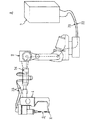
図1は、第1実施形態に係る接合装置Aの概略構成を示しており、この接合装置Aは、例えば自動車ボディ等に用いられるアルミニウム合金等からなるアルミニウム板(一方のワーク)W1と鋼板(他方のワーク)W2とをワークWとして、その両板面を重ねた状態で接合するために用いられる。この接合装置Aは、ロボット2と、そのロボット2の手首に取付けられる接合ガン1と、それらを制御する制御盤3とを備えている。
【0017】
前記ロボット2としては、例えば汎用の6軸垂直多関節型ロボットが用いられる。このロボット2は、接合ガン1を、前記アルミニウム板W1と鋼板W2との接合位置に位置づける機能を有している。
【0018】
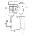
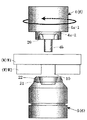
前記接合ガン1は、図2に示すように、前記アルミニウム板W1と鋼板W2とを接合するべく、接合用工具6として、回転ツール4と、受け具5とを備えている。回転ツール4は、接合軸X上に配設されており、この回転ツール4は、加圧軸モータ12により加圧のために上記接合軸Xに沿って昇降動されると共に、回転軸モータ11により接合軸Xを中心として回転されることになっている。上記回転軸モータ11としては、インダクションモータやサーボモータが用いることができ、上記加圧軸モータ12としては、サーボモータを用いることができる。受け具5は、前記回転ツール4に対向して配置されており、この位置状態は、略L字状のアーム13を利用し、その先端に受け具5を取付けることにより保持されている。尚、回転ツール4及び受け具5は、接合ガン1に対して着脱可能に取付けられている。
【0019】
上記接合ガン1における回転ツール4と受け具5とについて、図3に基づいて具体的に説明する。
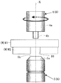
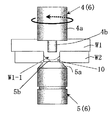
回転ツール4は、本体部4aと、その本体部4aの先端面から突出する突出部としてのピン部4bとを一体的に有している。本体部4aは、略円柱状に形成され、その配置は、その軸心が前記接合軸Xに合致するように設定されている。ピン部4bは、その軸心が本体部4aの軸心(接合軸X)に合致するように配置されつつ、本体部4aよりも小径となるようにして突出されており、その先端面は平坦面に形成されている。この場合、この先端面の形状は、より好ましくは、曲率半径40mm程度の曲面形状がよく、これにより、回転ツール4の回転時に求心力が発生して押し込みがスムーズとなる。受け具5は、前記回転ツール4における本体部4aと略同径とされた略円柱状に形成されており、その先端部形状は、その先端周縁部にその先端に向かうに従って縮径されるようにテーパ面5aが形成され、その先端面5bは平坦面に形成されている。
【0020】
前記制御盤3は、図1に示すように、前記ロボット2にハーネス31を介して接続されると共に、前記接合ガン1に、ハーネス33、中継ボックス34、ハーネス32を介して接続されている。この制御盤3は、ロボット2の6軸と、接合ガン1における回転軸モータ11及び加圧軸モータ12の2軸の合計8軸を同期制御するように構成されている。
【0021】
次に、上記接合装置Aを用いて、ワークWの接合方法について具体的に説明する。この接合方法は、接合すべきワークWとして、異種材料のもの、特に軟質性が相対的に異なるものに対して適用できることになっており、そのうち、軟質性が低いワーク(硬度が相対的に高いもの)に取付け孔として貫通孔が形成されている。本実施形態においては、前述の如く、アルミニウム板(一方のワーク)W1,鋼板(他方のワーク)W2が接合すべきワークWとされ、そのうち、鋼板W2の接合すべき部分(重ねる部分)に貫通孔10が形成されている。
【0022】
先ず、接合すべきアルミニウム板W1と鋼板W2とが、所定の状態で所定位置に固定される。これは、ロボット2の作業領域における所定位置に固定される図示を略す治具に、アルミニウム板W1と鋼板W2とをセットすることにより行われることになっており、このセットにおいて、アルミニウム板W1と鋼板W2との接合すべき部分が互いに重ねた状態とされると共にその重ね部分に貫通孔10が位置されることになっている。
【0023】
次に、図3に示すように、接合ガン1がロボット2によって所定の接合位置に位置づけられる。すなわち、接合ガン1が、受け具5を鋼板W2に対向させるように配置させつつ、その受け具5と回転ツール4との間にワークWの接合位置を位置させるように移動され、その接合ガン1の接合軸X上にワークWの接合位置が位置される。そしてこの後、接合ガン1が移動されて、受け具5の先端面5bが鋼板W2の貫通孔10を塞ぐように該鋼板W2に当接される。
【0024】
次に、図4に示すように、回転状態の回転ツール4のピン部4bと受け具5とによりワークWが把持される。すなわち、回転ツール4は、接合軸Xを中心として回転され、その回転状態を維持しつつ受け具5に向けて移動され、回転ツール4のピン部4bと受け具5とにより、その回転ツール4の回転を維持しつつ、ワークWは把持される。これにより、ワークWとピン部4bとの間に摩擦熱が発生することになり、その摩擦熱によりワークWは軟化することになる。
【0025】
次に、図5に示すように、さらに回転ツール4が回転状態を維持しつつ受け具5に向けて移動されて、ワークWは、回転状態の回転ツール4と受け具5とにより加圧される。これにより、回転ツール4が、軟化したアルミニウム板W1内に進入するに伴い、アルミニウム板W1のアルミ材(一部材料)W1−1が鋼板W2の貫通孔10内に押し込まれることになり、アルミニウム板W1のアルミ材W1−1は貫通孔10内に充填される。
【0026】
続いて、図6に示すように、回転ツール4がさらに受け具5に向けて移動されて、そのピン部4bが貫通孔10内に進入される。これにより、ピン部4bのその軸心を中心とした回転を通じて貫通孔10内に塑性流動が生じることになり、回転ツール4(軟化熱)に基づく鋼板W2表面の軟化に伴い、貫通孔10内周面全体に対して圧接力が生じ、アルミ材W1−1と鋼板W2とは強固に接合(固相接合)される。このとき、鋼板W2の板面と本体部4aの先端面(ピン部4bと本体部4aとの段差部)との間にも、回転ツール4(本体部4a)の回転に基づく塑性流動、軟化現象が生じており、アルミニウム板W1と鋼板W2との境界面は、貫通孔10周縁部においても、強固に接合されることになる。この圧接力が生じ接合が行われる部分を、図6において、太線をもって示すと共に、その部分を符号Sをもって示す。
【0027】
この場合、受け具5のテーパ面5aと鋼板W2の貫通孔10の周縁部とが当接されて、受け具5と鋼板W2との接触面積ができるだけ小さくされており、ワークWを軟化するための軟化熱が受け具5を通じて逃げることが抑制されている。その一方、受け具5のテーパ面5aは、軟化した鋼板W2の貫通孔10周縁部をアルミニウム板W1に向けて撓ませることになり、貫通孔10の周縁部10aは、図6に示すように、軟化しているアルミニウム板W1内に進入することになる。このため、そのアルミニウム板W1内に進入した貫通孔10周縁部10aによっても、接合強度が向上される。
【0028】
この後、設定時間が経過すると、回転ツール4と受け具5とは、ワークWからそれぞれ離間され、それらは、次の処理のために待機される。この場合、回転ツール4は、回転状態が維持しつつワークWから離間される。したがって、回転ツール4及び受け具5がワークWから離間されることにより、塑性流動していたワークWは急激に冷却され、アルミニウム板W1と鋼板W2とは接合される。
【0029】
図7〜図9はは第2実施形態、図10は第3実施形態、図11は第4実施形態、図12は第5実施形態を示す。この各実施形態において、前記第1実施形態及びその他の実施形態と同一構成要素については同一符号を付してその説明を省略する。
【0030】
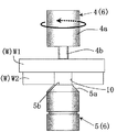
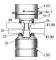
図7〜図9に示す第2実施形態は、前記第1実施形態の場合よりも一層接合強度の向上を図るべく、鋼板W2をアルミニウム板W1とアルミ材W1−1で挟持したものである。この第2実施形態においては、回転ツール4に関し、本体部4aが大径部4a−1とそれよりも縮径された中径部4a−2とを有しており、この本体部4aは、大径部4a−1と中径部4a−2とにより段付き構造とされている。ピン部4bは中径部4a−2の先端面に設けられるが、この中径部4a−2の先端面には、ピン部4bを中心としてその周囲に環状溝20が形成され、この環状溝20が、中径部4a−2の先端面がアルミニウム板W1に当接したとき、アルミニウム板W1の一部材料であるアルミ材W1−1の逃げ空間を確保することになっている。
【0031】
一方、受け具5の先端面には、前記貫通孔10を通じて鋼板W2の外側にアルミ材W1−1を確保すべく、凹所21が形成されている。この凹所21は、先端に向かうに従って拡径されるように設定され、その凹所21の開口径は、貫通孔10の径よりも大きなものとされている。また、本実施形態においては、凹所21の開口周縁部に環状の突部22が設けられている。この環状の突部22は、その内周面が、凹所21内周面に滑らかに連続すべく、先端に向かうに従って拡径されると共に、その突部22の肉厚は、先端の肉厚をできるだけ薄くすべく、先端に向かうほど短くされている。
【0032】
このような回転ツール4と受け具5とを用いてアルミニウム板W1と鋼板W2とを接合する場合には、受け具5が、その凹所21が鋼板W2の貫通孔10に臨むようにしてその鋼板W2に当接され、その下で、回転ツール4によりワークWに対して加圧される。これにより、前記第1実施形態同様、ワークWに摩擦熱が発生し、ワークWは軟化することになる。
【0033】
この状態の下で、回転ツール4の加圧動作がさらに続行されると、軟化したアルミ材W1−1がピン部4bにより貫通孔10を介して受け具5の凹所21内に押し込まれることになり(図8の矢印参照)、アルミ材W1−1は、貫通孔10外において、貫通孔10の径方向外方に拡がった状態で存在し、アルミ材W1−1とアルミニウム板W1とは鋼板W2を挟持することになる。このため、機械的に強固な係合関係が確保されることになり、剥離方向において接合強度が向上されることになる。
【0034】
また、この間、貫通孔10内においては、進入してくるピン部4bの軸心を中心としてアルミ材W1−1の塑性流動が生じることになり、この塑性流動と鋼板W2の軟化とにより、貫通孔10内周面に圧接力が生じ、アルミ材W1−1と鋼板W2の貫通孔10の全内周面とは強固に接合されることになる。このとき、鋼板W2の板面と中径部4a−2の先端面、鋼板W2の板面と大径部4a−1の先端面との間にも、回転ツール4(大径部4a−1、中径部4a−2)の回転に基づく塑性流動、軟化現象が生じており、アルミニウム板W1と鋼板W2との境界面は、貫通孔10周縁部においても、強固に接合されることになる。この圧接力が生じ接合が行われる部分を、図9において、太線をもって示すと共に、その部分を符号Sをもって示す。
【0035】
上記回転ツール4の加圧動作に際しては、それに伴い、受け具5の環状の突部22が鋼板W2をアルミニウム板W1に向けて押圧することになる。このため、その押圧力に基づき、アルミニウム板W1の軟化したアルミ材W1−1が回転ツール4の環状溝20に入り込むことになる一方、受け具5の環状の突部22が鋼板W2に入り込んで、軟化した鋼板W2の貫通孔10周縁部をアルミニウム板W1に向けて撓ませることになり、その貫通孔10の周縁部10aは、図9に示すように、軟化しているアルミニウム板W1内に容易に進入することになる。このため、そのアルミニウム板W1内に大きく進入した貫通孔周縁部10aによっても、せん断方向において接合強度が向上されることになる。
【0036】
またこの接合工程の間においては、受け具5の環状の突部22と鋼板W2の貫通孔10の周縁部とが当接されて、受け具5と鋼板W2との接触面積ができるだけ小さくされている。このため、ワークWを軟化するための軟化熱が受け具5を通じて逃げることが極力抑制される。その一方、本実施形態においては、回転ツール4の大径部4a−1がアルミニウム板W1と当接して、その回転に基づき摩擦熱を増加させることになっている。このため、本実施形態においては、ワークWに対して十分な軟化熱を供給できることになっている。尚、この大径部4a−1は、アルミニウム板W1と当接することにより、単位面積当たりの加圧力を低下させ、ワークWへの回転ツール4の進入速度が過速度になることを防止している。
【0037】
そしてこの後、設定時間が経過すると、回転ツール4と受け具5とは、ワークWからそれぞれ離間され、それらは、次の処理のために待機される。この場合、回転ツール4は、回転状態が維持しつつワークWから離間される。したがって、回転ツール4及び受け具5がワークWから離間されることにより、ワークWは急激に冷却され、アルミニウム板W1と鋼板W2とは強固に接合されることになる。
【0038】
図10に示す第3実施形態は、第2実施形態の変形例を示す。この第3実施形態においては、図10に示すように、本体部4aが一定の径とされ、その先端部が段付きでないものとされている。
【0039】
図11に示す第4実施形態は、第2実施形態の変形例を示す。この第4実施形態においては、図11に示すように、受け具5における環状の突部22も、回転ツール4における環状溝20も省かれており、第2実施形態に係る接合用工具6をできるだけ簡素な構成としたものとされている。
【0040】
図12に示す第5実施形態は、ロボット2と別に設置された架台8に前記各実施形態に係る接合ガン1を取付ける一方、ロボット2によりワークWの接合のための位置決めを行うようにしたものを示している。このため、ロボット2の手首に、接合ガン1に代えて、ワークWを保持するためのハンドリングツール7が取付けられている。勿論、ロボット2は、分岐ボックス35、ハーネス31を介して制御盤3に接続され、接合ガン1は、ハーネス33、中継ボックス34、ハーネス32を介して制御盤3に接続されると共に、ハーネス33、中継ボックス34、ハーネス36を介して上記分岐ボックス35に接続されており、それらは、所定の制御が行われることになっている。
【0041】
以上実施形態について説明したが本発明にあっては次のような態様を包含する。
1)鋼板W2の貫通孔10の内周面が、酸化膜により形成されていないことが好ましい。固相接合の強度を高める上で有利となるからである。
2)鋼板としては、亜鉛鋼板が好ましい。亜鉛とアルミニウムとが反応して、接合強度の向上を図ることができるからである。
3)受け具5もその軸心(接合軸X)を中心として回転させること。
4)第1実施形態において、本体部4aの先端部を段付きにして、摩擦熱をより確保すると共に、アルミニウム板W1に対する接触面積(単位面積当たりの加圧力)を変化させて、加圧速度を調整すること。
【0042】
尚、本発明の目的は、明記されたものに限らず、実質的に好ましい或いは利点として載されたものに対応したものを提供することをも含むものである。
【図面の簡単な説明】
【図1】第1実施形態に係る接合装置の概略構成を示す図。
【図2】第1実施形態に係る接合ガンの概略構成を示す図。
【図3】第1実施形態に係る接合用工具を示す図。
【図4】図3の状態に続く接合工程を示す図。
【図5】図4の状態に続く接合工程を示す図。
【図6】図5の状態に続く接合工程を示す図。
【図7】第2実施形態に係る接合用工具を示す図。
【図8】図7の状態に続く接合工程を示す図。
【図9】図8の状態に続く接合工程を示す図。
【図10】第3実施形態に係る接合用工具を示す図。
【図11】第4実施形態に係る接合用工具を示す図。
【図12】第5実施形態に係る接合装置の概略構成を示す図。
【符号の説明】
1 接合ガン
4 回転ツール
4b ピン部
5 受け具
6 接合用工具
10 貫通孔
20 環状溝(逃げ空間)
21 凹所
22 突部
W ワーク
W1 アルミニウム板
W2 鋼板[0001]
TECHNICAL FIELD OF THE INVENTION
The present invention relates to a welding method using friction stirring and a welding tool used in the method.
[0002]
[Prior art]
As a joining method using friction stirring, as shown in
[0003]
[Patent Document 1]
JP-A-2001-314982
[Problems to be solved by the invention]
However, in the above-described joining method, one work cannot be deeply inserted into the other work by the rotating tool, and joining of the overlapped works is performed in a shallow portion near the overlapping surface of the works (the rotating tool is not plastic). Fluidized part). For this reason, a further improvement in bonding strength is desired.
[0005]
The present invention has been made in view of the above circumstances, and a first technical problem thereof is to provide a joining method using friction stirrer capable of improving the joining strength between stacked workpieces. It is in.
A second technical problem is to provide a joining tool for performing the above joining method.
[0006]
[Means for Solving the Problems]
In order to achieve the first technical problem, in the present invention (the invention according to claim 1),
The rotating tool is brought into contact with one of the stacked plate-shaped works on one side in the stacking direction of the work, and the rotating tool is applied to the stacked work in the stacking direction of the work. In a joining method using friction stirring to apply pressure and apply frictional heat based on rotation about the pressing direction of the pressing force,
In the other work on the other side in the stacking direction of the work, a through-hole is provided in advance so as to face a pressing area of the rotating tool,
The one work is pushed into the through-hole with the pressurization of the rotating tool. Preferred embodiments of the first aspect are as described in the second to fifth aspects.
[0007]
In order to achieve the second technical problem, in the present invention (the invention according to claim 6),
A joining tool for joining one plate-shaped work and another plate-shaped work having a through-hole in a portion to be joined in a stacked state,
A rotary tool for applying a pressing force in the direction in which the workpieces are overlapped in a state in which the one of the workpieces is in contact with the workpiece and for applying frictional heat based on rotation of the pressing force about the pressing direction; A receiving tool that is arranged to face and receives the two works in contact with the other work,
The receiving member is provided with a recess having an opening larger than the diameter of the through hole in the other work. A preferable aspect of the sixth aspect is as described in the seventh aspect.
[0008]
【The invention's effect】
According to the first aspect of the present invention, with the pressurization of the rotating tool, a part of the material of one of the works softened by frictional heat based on the rotation is sufficiently pushed into the through-hole of the other work. Part of the material of one of the workpieces filled in the hole is plastically flowed by the rotating tool that has entered. With this, as the surface of the other work is softened, a pressing force is generated on the inner peripheral surface of the through hole and the like, and the joining is performed. For this reason, the strong joining is performed under a wide joining area including the inner peripheral surface of the through hole, and the joining strength between the stacked workpieces can be improved.
[0009]
According to the invention described in
[0010]
According to the third aspect of the present invention, the pressing force is applied to the peripheral portion of the through-hole from the outside of the other work with the pressing of the rotary tool, while the pressing force acts on one of the works. Since the space is ensured, as the work softens due to the frictional heat based on the rotating tool, part of the material of one work escapes to the escape space, while the peripheral edge of the through hole contacting the other work rises, The protruding portion of the other work enters the one work. For this reason, a particularly strong engagement relationship is secured in the shearing direction of the two works (the direction along the plate surface of the works), and the joining strength between the stacked works can be further improved. .
[0011]
According to the invention described in
[0012]
According to the invention described in
[0013]
According to the invention as set forth in
In addition, the material of one of the workpieces extruded to the other side in the stacking direction of the workpieces through the through-hole exerts a force toward the rotating tool on the peripheral edge of the through-hole. As a result, as the other work (the inner peripheral surface of the through hole, the inner peripheral edge portion, etc.) is softened, the peripheral portion of the through hole that comes into contact with the one work can be easily raised. For this reason, the swelling portion of the other work easily enters into one of the works, which is preferable in improving the joining strength between the stacked works.
[0014]
According to the invention described in claim 7, the pressing force against the other work is obtained by the annular projection of the receiving tool, and the clearance space is obtained by the annular groove of the rotating tool. A joining tool that can specifically carry out such a method can be provided.
[0015]
BEST MODE FOR CARRYING OUT THE INVENTION
Hereinafter, embodiments of the present invention will be described with reference to the drawings.
First, before describing the method according to the present invention, a specific bonding apparatus for performing the method according to the present invention will be described.
[0016]
FIG. 1 shows a schematic configuration of a joining device A according to a first embodiment. The joining device A includes, for example, an aluminum plate (one work) W1 made of an aluminum alloy or the like used for an automobile body or the like and a steel plate (one work piece). The other work W2 is used to join the work W as a work W in a state where both plate surfaces are overlapped. The joining apparatus A includes a
[0017]
As the
[0018]
As shown in FIG. 2, the joining
[0019]
The
The
[0020]
As shown in FIG. 1, the
[0021]
Next, a method of joining the work W using the joining apparatus A will be specifically described. This joining method can be applied to a work W to be joined, which is made of a different material, particularly one having a relatively different softness, and among them, a work having a low softness (having a relatively high hardness). Has a through hole as an attachment hole. In the present embodiment, as described above, the aluminum plate (one work) W1 and the steel plate (the other work) W2 are the works W to be joined, and among these, the work is to penetrate through the part to be joined (overlapping part) of the steel sheet W2. A
[0022]
First, the aluminum plate W1 and the steel plate W2 to be joined are fixed at a predetermined position in a predetermined state. This is to be performed by setting the aluminum plate W1 and the steel plate W2 on a jig (not shown) fixed at a predetermined position in the work area of the
[0023]
Next, as shown in FIG. 3, the joining
[0024]
Next, as shown in FIG. 4, the workpiece W is gripped by the
[0025]
Next, as shown in FIG. 5, the
[0026]
Subsequently, as shown in FIG. 6, the
[0027]
In this case, the
[0028]
Thereafter, when the set time has elapsed, the
[0029]
7 to 9 show a second embodiment, FIG. 10 shows a third embodiment, FIG. 11 shows a fourth embodiment, and FIG. 12 shows a fifth embodiment. In each of the embodiments, the same components as those in the first embodiment and other embodiments are denoted by the same reference numerals, and description thereof will be omitted.
[0030]
In the second embodiment shown in FIGS. 7 to 9, the steel plate W2 is sandwiched between the aluminum plate W1 and the aluminum material W1-1 in order to further improve the joining strength as compared with the first embodiment. In the second embodiment, with respect to the
[0031]
On the other hand, a
[0032]
When joining the aluminum plate W1 and the steel plate W2 by using such a
[0033]
In this state, when the pressurizing operation of the
[0034]
Meanwhile, in the through
[0035]
During the pressurizing operation of the
[0036]
During this joining step, the
[0037]
After this, when the set time has elapsed, the
[0038]
The third embodiment shown in FIG. 10 is a modification of the second embodiment. In the third embodiment, as shown in FIG. 10, the
[0039]
The fourth embodiment shown in FIG. 11 is a modification of the second embodiment. In the fourth embodiment, as shown in FIG. 11, the
[0040]
In the fifth embodiment shown in FIG. 12, the joining
[0041]
Although the embodiments have been described above, the present invention includes the following aspects.
1) It is preferable that the inner peripheral surface of the through
2) As the steel sheet, a zinc steel sheet is preferable. This is because zinc and aluminum react with each other to improve bonding strength.
3) The
4) In the first embodiment, the tip portion of the
[0042]
It should be noted that the object of the present invention is not limited to the specified ones, but also includes providing ones corresponding to those described as substantially preferable or advantageous.
[Brief description of the drawings]
FIG. 1 is a diagram showing a schematic configuration of a bonding apparatus according to a first embodiment.
FIG. 2 is a diagram showing a schematic configuration of a joining gun according to the first embodiment.
FIG. 3 is a view showing a joining tool according to the first embodiment.
FIG. 4 is a view showing a bonding step following the state in FIG. 3;
FIG. 5 is a view showing a bonding step following the state of FIG. 4;
FIG. 6 is a view showing a bonding step following the state of FIG. 5;
FIG. 7 is a view showing a joining tool according to a second embodiment.
FIG. 8 is a view showing a bonding step following the state in FIG. 7;
FIG. 9 is a view showing a bonding step following the state in FIG. 8;
FIG. 10 is a view showing a joining tool according to a third embodiment.
FIG. 11 is a view showing a joining tool according to a fourth embodiment.
FIG. 12 is a diagram showing a schematic configuration of a joining device according to a fifth embodiment.
[Explanation of symbols]
DESCRIPTION OF
21
Claims (7)
前記ワークの重ね方向他方側における他方のワークに、予め、前記回転ツールの加圧領域に臨むようにして貫通孔を設け、
前記回転ツールの加圧に伴い、前記貫通孔内に前記一方のワークを押し込む、ことを特徴とする摩擦撹拌を用いた接合方法。The rotating tool is brought into contact with one of the stacked plate-shaped works on one side in the stacking direction of the work, and the rotating tool is applied to the stacked work in the stacking direction of the work. In a joining method using friction stirring to apply pressure and apply frictional heat based on rotation about the pressing direction of the pressing force,
In the other work on the other side in the stacking direction of the work, a through-hole is provided in advance so as to face a pressing area of the rotating tool,
A joining method using friction agitation, wherein the one of the works is pushed into the through-hole with the pressurization of the rotary tool.
前記貫通孔内に押し込まれた前記一方のワークの材料を、該貫通孔を経てワークの重ね方向他方側に押し出すと共に該貫通孔外において該貫通孔の径方向外方に拡がるようにする、
ことを特徴とする摩擦撹拌を用いた接合方法。In claim 1,
The material of the one work pushed into the through hole is pushed out to the other side in the stacking direction of the work through the through hole, and spreads radially outward of the through hole outside the through hole.
A joining method using friction stirring.
前記回転ツールの加圧に伴い、前記貫通孔周縁部に、前記他方のワーク外側から押圧力を付与する一方、前記一方のワークに前記押圧力が作用する領域において逃げ空間を確保する、
ことを特徴とする摩擦撹拌を用いた接合方法。In claim 1 or 2,
With the pressurization of the rotating tool, while applying a pressing force from the outside of the other work to the peripheral portion of the through-hole, a clearance space is secured in a region where the pressing force acts on the one work.
A joining method using friction stirring.
前記一方のワーク及び他方のワークは、異種材料であり、
前記他方のワークに対して前記一方のワークが、軟質材料とされている、
ことを特徴とする摩擦撹拌を用いた接合方法。In any one of claims 1 to 3,
The one workpiece and the other workpiece are different materials,
The one work is a soft material with respect to the other work,
A joining method using friction stirring.
前記一方のワークがアルミニウム板とされ、
前記他方のワークが鋼板とされている、
ことを特徴とする摩擦撹拌を用いた接合方法。In claim 4,
The one of the workpieces is an aluminum plate,
The other work is a steel plate,
A joining method using friction stirring.
前記一方のワークに対して当接された状態でワークの重ね方向に加圧力を付与すると共に該加圧力の加圧方向を中心とした回転に基づく摩擦熱を付与する回転ツールと、該回転ツールに対向して配置され前記両ワークを前記他方のワークに当接した状態で受け止める受け具とを備え、
前記受け具が、前記他方のワークにおける貫通孔の径よりも大きな開口を有する凹所を備えている、
ことを特徴とする接合用工具。A joining tool for joining one plate-shaped work and another plate-shaped work having a through-hole in a portion to be joined in a stacked state,
A rotary tool for applying a pressing force in the direction in which the workpieces are overlapped in a state in which the one of the workpieces is in contact with the workpiece and for applying frictional heat based on rotation of the pressing force about the pressing direction; A receiving tool that is arranged to face and receives the two works in contact with the other work,
The receiving device includes a recess having an opening larger than the diameter of the through hole in the other work,
A joining tool characterized by the above-mentioned.
前記回転ツールに、前記一方のワークに対して加圧力と回転に基づく摩擦熱とを付与する突出部と、該突出部を中心として環状に形成される環状溝とが備えられ、
前記受け具に、前記凹所の開口周縁部に環状の突部が設けられている、
ことを特徴とする接合用工具。In claim 6,
The rotating tool is provided with a protrusion for applying frictional heat based on rotation and rotation to the one of the workpieces, and an annular groove formed annularly around the protrusion,
In the receiving device, an annular protrusion is provided on an opening peripheral portion of the recess,
A joining tool characterized by the above-mentioned.
Priority Applications (8)
| Application Number | Priority Date | Filing Date | Title |
|---|---|---|---|
| JP2002313019A JP3864888B2 (en) | 2002-10-28 | 2002-10-28 | Joining method using friction stir |
| DE60312793T DE60312793T2 (en) | 2002-10-28 | 2003-10-27 | Method and use of a device for friction stir welding |
| EP03024538A EP1415752B1 (en) | 2002-10-28 | 2003-10-27 | Method and use of a device for friction agitation welding |
| PCT/CZ2003/000061 WO2004037478A1 (en) | 2002-10-28 | 2003-10-29 | Method and device for friction agitation welding |
| US10/500,215 US20050145678A1 (en) | 2002-10-28 | 2003-10-29 | Method and device for friction agitation welding |
| AU2003277797A AU2003277797A1 (en) | 2002-10-28 | 2003-10-29 | Method and device for friction agitation welding |
| US10/695,455 US20040144830A1 (en) | 2002-10-28 | 2003-10-29 | Method and device for friction agitation welding |
| US11/387,687 US20060163326A1 (en) | 2002-10-28 | 2006-03-24 | Method and device for friction agitation welding |
Applications Claiming Priority (1)
| Application Number | Priority Date | Filing Date | Title |
|---|---|---|---|
| JP2002313019A JP3864888B2 (en) | 2002-10-28 | 2002-10-28 | Joining method using friction stir |
Publications (2)
| Publication Number | Publication Date |
|---|---|
| JP2004148320A true JP2004148320A (en) | 2004-05-27 |
| JP3864888B2 JP3864888B2 (en) | 2007-01-10 |
Family
ID=32089475
Family Applications (1)
| Application Number | Title | Priority Date | Filing Date |
|---|---|---|---|
| JP2002313019A Expired - Fee Related JP3864888B2 (en) | 2002-10-28 | 2002-10-28 | Joining method using friction stir |
Country Status (6)
| Country | Link |
|---|---|
| US (3) | US20050145678A1 (en) |
| EP (1) | EP1415752B1 (en) |
| JP (1) | JP3864888B2 (en) |
| AU (1) | AU2003277797A1 (en) |
| DE (1) | DE60312793T2 (en) |
| WO (1) | WO2004037478A1 (en) |
Cited By (17)
| Publication number | Priority date | Publication date | Assignee | Title |
|---|---|---|---|---|
| JP2006021217A (en) * | 2004-07-07 | 2006-01-26 | Kawasaki Heavy Ind Ltd | Friction stir welding apparatus for spot welding |
| JP2006035265A (en) * | 2004-07-27 | 2006-02-09 | Mazda Motor Corp | Friction welding method and device therefor |
| JP2006095585A (en) * | 2004-09-30 | 2006-04-13 | Mazda Motor Corp | Friction point welding method |
| JP2006136906A (en) * | 2004-11-10 | 2006-06-01 | Honda Motor Co Ltd | Method for joining laminated portion |
| JP2006212657A (en) * | 2005-02-02 | 2006-08-17 | Kawasaki Heavy Ind Ltd | Welding tool for friction stir welding apparatus |
| JP2006289409A (en) * | 2005-04-08 | 2006-10-26 | Honda Motor Co Ltd | Method for joining laminated portion |
| JP2006326664A (en) * | 2005-05-30 | 2006-12-07 | Mazda Motor Corp | Friction point joining method and device therefor |
| JP2007007729A (en) * | 2005-06-27 | 2007-01-18 | Gkss Forschungszentrum Geesthacht Gmbh | Apparatus for friction stir welding |
| JP2007090393A (en) * | 2005-09-29 | 2007-04-12 | Mazda Motor Corp | Method and apparatus for friction spot welding |
| JP2007136505A (en) * | 2005-11-17 | 2007-06-07 | Hino Motors Ltd | Material joining method |
| JP2007160373A (en) * | 2005-12-15 | 2007-06-28 | Hino Motors Ltd | Method of fitting member |
| JP2008087009A (en) * | 2006-09-29 | 2008-04-17 | Hitachi Ltd | Clinching method and clinching tool |
| WO2008056449A1 (en) * | 2006-11-10 | 2008-05-15 | Hino Motors, Ltd. | Structure for joining members |
| JP2008137072A (en) * | 2006-11-10 | 2008-06-19 | Hino Motors Ltd | Structure for joining members |
| JP2012040583A (en) * | 2010-08-17 | 2012-03-01 | Osaka Univ | Method for manufacturing metal material |
| JP2015139789A (en) * | 2014-01-27 | 2015-08-03 | 新日鐵住金株式会社 | Method for friction stir welding of dissimilar member and welded joint |
| CN111867778A (en) * | 2018-05-09 | 2020-10-30 | 川崎重工业株式会社 | Friction engagement device and method of operating the same |
Families Citing this family (15)
| Publication number | Priority date | Publication date | Assignee | Title |
|---|---|---|---|---|
| JP3726786B2 (en) * | 2002-07-31 | 2005-12-14 | マツダ株式会社 | Joining method and joining tool |
| JP3931790B2 (en) * | 2002-11-01 | 2007-06-20 | マツダ株式会社 | Friction stir processing method and apparatus therefor |
| US20060138197A1 (en) * | 2003-06-12 | 2006-06-29 | Kinya Aota | Friction stirring-welding method |
| JP4148152B2 (en) * | 2004-02-16 | 2008-09-10 | マツダ株式会社 | Friction spot joint structure |
| FR2869248B1 (en) * | 2004-04-27 | 2007-06-29 | Snecma Moteurs Sa | PROCESS FOR BINDING BY FRICTION WELDING OF A HOLE OF A METAL PIECE |
| JP4729921B2 (en) | 2004-12-24 | 2011-07-20 | マツダ株式会社 | Friction spot welding method and apparatus |
| US20070215675A1 (en) * | 2006-03-17 | 2007-09-20 | Lockheed Martin Corporation | Friction stir welding process to join two or more members in forming a three-dimensional joint |
| EP1864747A1 (en) * | 2006-06-07 | 2007-12-12 | Abb Ab | System and method for frictional stir welding with means for supporting the workpiece during welding moving synchronously with the rotary tool relative to the workpiece |
| US20090148719A1 (en) * | 2007-12-07 | 2009-06-11 | Alcoa Inc. | Friction-stir weldments and systems and methods for producing the same |
| US8317079B2 (en) * | 2008-10-08 | 2012-11-27 | GM Global Technology Operations LLC | Clinching method and tool for performing the same |
| US8963043B2 (en) * | 2009-05-07 | 2015-02-24 | Innovative Weld Solutions, Ltd. | Welding assembly and associated method for welding and heat treating metals and metal alloys |
| DE102010003742A1 (en) * | 2010-04-08 | 2011-10-13 | Airbus Operations Gmbh | Method and apparatus for friction stir welding of two components |
| CN109070262B (en) * | 2016-03-31 | 2021-09-10 | 杰富意钢铁株式会社 | Friction stir welding method and apparatus for structural steel |
| CN109433997A (en) * | 2018-12-27 | 2019-03-08 | 南京航空航天大学 | A kind of spin friction squeezed riveting device and its clinching method |
| CN112518077B (en) * | 2020-10-29 | 2022-03-01 | 烟台大学 | Online compensation type material combining device |
Family Cites Families (14)
| Publication number | Priority date | Publication date | Assignee | Title |
|---|---|---|---|---|
| US5769306A (en) * | 1996-05-31 | 1998-06-23 | The Boeing Company | Weld root closure method for friction stir welds |
| US6290117B1 (en) * | 1998-02-17 | 2001-09-18 | Hitachi, Ltd. | Friction stir welding method and friction stir welding apparatus |
| US5975406A (en) * | 1998-02-27 | 1999-11-02 | The Boeing Company | Method to repair voids in aluminum alloys |
| ATE234696T1 (en) * | 1998-09-25 | 2003-04-15 | Univ Dresden Tech | METHOD AND DEVICE FOR CONNECTING OVERLAPPING PLATE-SHAPED COMPONENTS |
| NL1011908C1 (en) * | 1999-04-27 | 2000-10-30 | Fokker Aerostructures Bv | Friction stir welding. |
| US6460752B1 (en) * | 2000-04-04 | 2002-10-08 | The Boeing Company | Method of friction stir welding with grooved backing member |
| JP3867475B2 (en) * | 2000-04-28 | 2007-01-10 | マツダ株式会社 | Method for processing metal members |
| JP3429475B2 (en) * | 2000-05-08 | 2003-07-22 | 川崎重工業株式会社 | Spot joining apparatus and spot joining method |
| JP3553012B2 (en) * | 2000-11-17 | 2004-08-11 | 株式会社日立製作所 | Friction stir welding method |
| US6769595B2 (en) * | 2000-12-20 | 2004-08-03 | Alcoa Inc. | Friction plunge riveting |
| ES2250616T3 (en) * | 2001-03-29 | 2006-04-16 | Mazda Motor Corporation | METHOD AND APPARATUS OF UNION THAT USE AGITATION WITH BRUSHING. |
| US6742697B2 (en) * | 2002-04-29 | 2004-06-01 | The Boeing Company | Joining of structural members by friction plug welding |
| JP3726786B2 (en) * | 2002-07-31 | 2005-12-14 | マツダ株式会社 | Joining method and joining tool |
| JP2004106037A (en) * | 2002-09-20 | 2004-04-08 | Hitachi Ltd | Method for bonding metal |
-
2002
- 2002-10-28 JP JP2002313019A patent/JP3864888B2/en not_active Expired - Fee Related
-
2003
- 2003-10-27 EP EP03024538A patent/EP1415752B1/en not_active Expired - Fee Related
- 2003-10-27 DE DE60312793T patent/DE60312793T2/en not_active Expired - Lifetime
- 2003-10-29 AU AU2003277797A patent/AU2003277797A1/en not_active Abandoned
- 2003-10-29 WO PCT/CZ2003/000061 patent/WO2004037478A1/en active Application Filing
- 2003-10-29 US US10/500,215 patent/US20050145678A1/en not_active Abandoned
- 2003-10-29 US US10/695,455 patent/US20040144830A1/en not_active Abandoned
-
2006
- 2006-03-24 US US11/387,687 patent/US20060163326A1/en not_active Abandoned
Cited By (25)
| Publication number | Priority date | Publication date | Assignee | Title |
|---|---|---|---|---|
| JP2006021217A (en) * | 2004-07-07 | 2006-01-26 | Kawasaki Heavy Ind Ltd | Friction stir welding apparatus for spot welding |
| JP4537132B2 (en) * | 2004-07-07 | 2010-09-01 | 川崎重工業株式会社 | Friction stir welding method for spot welding |
| JP2006035265A (en) * | 2004-07-27 | 2006-02-09 | Mazda Motor Corp | Friction welding method and device therefor |
| JP4507743B2 (en) * | 2004-07-27 | 2010-07-21 | マツダ株式会社 | Friction welding method and apparatus |
| JP2006095585A (en) * | 2004-09-30 | 2006-04-13 | Mazda Motor Corp | Friction point welding method |
| JP2006136906A (en) * | 2004-11-10 | 2006-06-01 | Honda Motor Co Ltd | Method for joining laminated portion |
| JP4516410B2 (en) * | 2004-11-10 | 2010-08-04 | 本田技研工業株式会社 | Laminate joining method |
| JP2006212657A (en) * | 2005-02-02 | 2006-08-17 | Kawasaki Heavy Ind Ltd | Welding tool for friction stir welding apparatus |
| JP2006289409A (en) * | 2005-04-08 | 2006-10-26 | Honda Motor Co Ltd | Method for joining laminated portion |
| JP4516469B2 (en) * | 2005-04-08 | 2010-08-04 | 本田技研工業株式会社 | Laminate bonding method |
| JP2006326664A (en) * | 2005-05-30 | 2006-12-07 | Mazda Motor Corp | Friction point joining method and device therefor |
| JP4661367B2 (en) * | 2005-05-30 | 2011-03-30 | マツダ株式会社 | Friction spot welding method and apparatus |
| JP2007007729A (en) * | 2005-06-27 | 2007-01-18 | Gkss Forschungszentrum Geesthacht Gmbh | Apparatus for friction stir welding |
| JP4586698B2 (en) * | 2005-09-29 | 2010-11-24 | マツダ株式会社 | Friction spot welding device |
| JP2007090393A (en) * | 2005-09-29 | 2007-04-12 | Mazda Motor Corp | Method and apparatus for friction spot welding |
| JP2007136505A (en) * | 2005-11-17 | 2007-06-07 | Hino Motors Ltd | Material joining method |
| US7909229B2 (en) | 2005-11-17 | 2011-03-22 | Hino Motors, Ltd. | Method for joining material |
| JP2007160373A (en) * | 2005-12-15 | 2007-06-28 | Hino Motors Ltd | Method of fitting member |
| JP2008087009A (en) * | 2006-09-29 | 2008-04-17 | Hitachi Ltd | Clinching method and clinching tool |
| JP2008137072A (en) * | 2006-11-10 | 2008-06-19 | Hino Motors Ltd | Structure for joining members |
| WO2008056449A1 (en) * | 2006-11-10 | 2008-05-15 | Hino Motors, Ltd. | Structure for joining members |
| US8333314B2 (en) | 2006-11-10 | 2012-12-18 | Hino Motors, Ltd. | Structure for joining members |
| JP2012040583A (en) * | 2010-08-17 | 2012-03-01 | Osaka Univ | Method for manufacturing metal material |
| JP2015139789A (en) * | 2014-01-27 | 2015-08-03 | 新日鐵住金株式会社 | Method for friction stir welding of dissimilar member and welded joint |
| CN111867778A (en) * | 2018-05-09 | 2020-10-30 | 川崎重工业株式会社 | Friction engagement device and method of operating the same |
Also Published As
| Publication number | Publication date |
|---|---|
| EP1415752B1 (en) | 2007-03-28 |
| DE60312793D1 (en) | 2007-05-10 |
| US20060163326A1 (en) | 2006-07-27 |
| US20050145678A1 (en) | 2005-07-07 |
| DE60312793T2 (en) | 2008-01-24 |
| AU2003277797A1 (en) | 2004-05-13 |
| WO2004037478A1 (en) | 2004-05-06 |
| JP3864888B2 (en) | 2007-01-10 |
| AU2003277797A8 (en) | 2004-05-13 |
| EP1415752A1 (en) | 2004-05-06 |
| US20040144830A1 (en) | 2004-07-29 |
Similar Documents
| Publication | Publication Date | Title |
|---|---|---|
| JP2004148320A (en) | Method and tool for friction stir welding joint | |
| JP3726786B2 (en) | Joining method and joining tool | |
| JP3867475B2 (en) | Method for processing metal members | |
| JP3400409B2 (en) | Joining method and joining device | |
| JP4586698B2 (en) | Friction spot welding device | |
| EP1153694A2 (en) | Spot joining method and spot joining device | |
| US20170312989A9 (en) | Friction Stir Processing Tool Having Non-Circumferential Shoulder and Friction Stir Processing Method Performable Therewith | |
| JP2007203326A (en) | Friction stir welding equipment | |
| EP2008751A3 (en) | Friction stir welding method of joining at least two adjoining work-pieces with application of an adhesive between the at least two workpieces | |
| JP4183964B2 (en) | Friction stir welding equipment | |
| JP7101140B2 (en) | Friction stir welding tool | |
| JP2011115857A (en) | Friction stir welding device | |
| JP3534735B2 (en) | Spot joining system and fixing device | |
| JP4729921B2 (en) | Friction spot welding method and apparatus | |
| JP4740289B2 (en) | Friction stir welding equipment | |
| US11858060B2 (en) | Friction stir spot welding device and method for operating same | |
| JP2002096182A (en) | Bonding method, revolving tool and joining body by friction heating | |
| JP4172343B2 (en) | Friction spot welding method | |
| JP2018039017A (en) | Joining method | |
| JP2004148319A (en) | Friction stir welding apparatus | |
| JP2000094156A (en) | Frictional agitation joining method and frictional agitation joining device | |
| JP4853184B2 (en) | Friction spot welding device | |
| JP4517760B2 (en) | Friction spot welding method and apparatus | |
| US20200009682A1 (en) | Method for joining metal sheets and joined structure of metal sheets | |
| JP4661367B2 (en) | Friction spot welding method and apparatus |
Legal Events
| Date | Code | Title | Description |
|---|---|---|---|
| A977 | Report on retrieval |
Free format text: JAPANESE INTERMEDIATE CODE: A971007 Effective date: 20060602 |
|
| A131 | Notification of reasons for refusal |
Free format text: JAPANESE INTERMEDIATE CODE: A131 Effective date: 20060613 |
|
| A521 | Written amendment |
Free format text: JAPANESE INTERMEDIATE CODE: A523 Effective date: 20060814 |
|
| TRDD | Decision of grant or rejection written | ||
| A01 | Written decision to grant a patent or to grant a registration (utility model) |
Free format text: JAPANESE INTERMEDIATE CODE: A01 Effective date: 20060912 |
|
| A61 | First payment of annual fees (during grant procedure) |
Free format text: JAPANESE INTERMEDIATE CODE: A61 Effective date: 20060925 |
|
| R150 | Certificate of patent or registration of utility model |
Ref document number: 3864888 Country of ref document: JP Free format text: JAPANESE INTERMEDIATE CODE: R150 Free format text: JAPANESE INTERMEDIATE CODE: R150 |
|
| FPAY | Renewal fee payment (event date is renewal date of database) |
Free format text: PAYMENT UNTIL: 20091013 Year of fee payment: 3 |
|
| FPAY | Renewal fee payment (event date is renewal date of database) |
Free format text: PAYMENT UNTIL: 20101013 Year of fee payment: 4 |
|
| FPAY | Renewal fee payment (event date is renewal date of database) |
Free format text: PAYMENT UNTIL: 20111013 Year of fee payment: 5 |
|
| FPAY | Renewal fee payment (event date is renewal date of database) |
Free format text: PAYMENT UNTIL: 20111013 Year of fee payment: 5 |
|
| FPAY | Renewal fee payment (event date is renewal date of database) |
Free format text: PAYMENT UNTIL: 20121013 Year of fee payment: 6 |
|
| FPAY | Renewal fee payment (event date is renewal date of database) |
Free format text: PAYMENT UNTIL: 20131013 Year of fee payment: 7 |
|
| LAPS | Cancellation because of no payment of annual fees |