JP4183576B2 - Scanning surface shape measuring apparatus and surface shape measuring method - Google Patents
Scanning surface shape measuring apparatus and surface shape measuring method Download PDFInfo
- Publication number
- JP4183576B2 JP4183576B2 JP2003206673A JP2003206673A JP4183576B2 JP 4183576 B2 JP4183576 B2 JP 4183576B2 JP 2003206673 A JP2003206673 A JP 2003206673A JP 2003206673 A JP2003206673 A JP 2003206673A JP 4183576 B2 JP4183576 B2 JP 4183576B2
- Authority
- JP
- Japan
- Prior art keywords
- surface shape
- measurement
- test surface
- shape
- partial
- Prior art date
- Legal status (The legal status is an assumption and is not a legal conclusion. Google has not performed a legal analysis and makes no representation as to the accuracy of the status listed.)
- Expired - Fee Related
Links
Images


Landscapes
- Instruments For Measurement Of Length By Optical Means (AREA)
- Length Measuring Devices By Optical Means (AREA)
Description
【0001】
【発明の属する技術分野】
本発明は、被検面に対して干渉計を走査することにより、被検面の形状を測定する走査型面形状測定装置および面形状測定方法に関する。
【0002】
【従来の技術】
平面形状を高精度に測定する装置の1つとして、干渉計がある。干渉計は、基準となる参照面からの反射光と被検面からの反射光により干渉縞を発生させ、この干渉縞に基づいて被検面の形状を測定するものであり、レーザ光を観測領域に拡大して投射する光学系と、測定時に生じる干渉縞を結像する光学系と、結像された干渉縞像を電気信号に変換するCCDなどの撮像素子とを有する。干渉計の観測領域および横分解能は、光学設計と撮像素子の画素数から決まる。干渉計においては、観測領域を大きくすると、横分解能が低くなり、逆に、横分解能を高くすると、観測領域は狭くなる。よって、測定対象の被検面のサイズや測定時の横分解能に応じて干渉計を個別に選定する必要がある。さらに、観測領域が大きい干渉計においては、使用する光学部品が大きくなるので、装置サイズが大きくなり、また価格も高価になる傾向がある。
【0003】
観測領域が小さい干渉計を用いて大きな被検面の形状を測定する方法としては、被検面に対して干渉計を走査することにより、被検面形状を測定する方法がある。この方法の場合、被検面に対して高精度な面形状測定を行うには、走査時の運動誤差が非常に小さくなるような理想的な走査を行うことが要求される。また、精密工学会誌Vol.61,No.12,1995「非球面光学素子の超平滑研磨技術に関する研究(第1報)−オンマシン形状測定装置の開発−」に記載されているように、予め運動誤差を高精度に値付けし、補正するという方法がある。
【0004】
また、被検面に対して干渉計を走査することにより、被検面形状を測定する測定方法において、走査時の運動誤差の影響を受けずに被検面形状を測定するための手法が、「Measurement of large plane surface shape by connecting small-aperture interferograms」(Optical engineering Feb., 1994, Vol.33, No.2, (608))に提案されている。この手法は、被検面に対して観測領域を重複させながら干渉計を走査し、各観測領域からそれぞれ得られた各領域の形状を接続することによって被検面全体の形状を算出するものである。ここで、算出された互いに隣接する領域の形状を接続する際に、各領域の形状における重複領域のデータが一致するように、各領域の形状の傾斜成分が補正される。但し、この手法の場合、観測領域毎に十分に高い測定精度が要求される。
【0005】
【非特許文献1】
精密工学会誌Vol.61,No.12,1995「非球面光学素子の超平滑研磨技術に関する研究(第1報)−オンマシン形状測定装置の開発−」
【非特許文献2】
「Measurement of large plane surface shape by connecting small-aperture interferograms」(Optical engineering Feb., 1994, Vol.33, No.2, (608))
【0006】
【発明が解決しようとする課題】
しかしながら、上述した被検面に対して干渉計を走査する測定方法の場合は、走査時の運動誤差が非常に小さくなるような理想的な走査を行うことが可能な走査機構を実現することが、また、予め運動誤差を高精度に値付けして補正する方法の場合は、走査時の運動誤差を高精度に補正することが、それぞれ、現状では非常に難しい。
【0007】
また、運動誤差の影響を受けずに被検面形状を測定するための手法の場合は、観測領域毎に十分に高い測定精度が要求されるが、この要求通りの測定精度を実現することが現状では難しく、各観測領域からそれぞれ算出された形状には、要求された測定精度に対応する誤差より大きな誤差が存在することになる。その結果、算出された各領域の形状を接続する際に、それぞれの誤差が累積されて非常に大きなものとなり、十分に高い測定精度での被検面の形状を得ることは、困難であると考えられる。
【0008】
本発明は、上記課題を解決するためになされたもので、走査時の運動誤差の影響を減少させ、観測領域が小さい干渉計を用いて大きなサイズの被検面に対して高精度な面形状測定を行うことができる走査型面形状測定装置および面形状測定方法を提供することを目的とする。
【0009】
【課題を解決するための手段】
本発明は、上記目的を達成するため、被検面上の観測領域に対応する部分面と参照面とのそれぞれからの反射光により生じる干渉縞に基づいて前記観測領域に対応する部分面形状を測定する干渉計と、前記被検面上の少なくとも1つの位置との間の高さ方向の距離を検出する距離検出手段と、前記干渉計と前記距離検出手段とを搭載する搭載部を有し、前記搭載部を複数の測定位置へ順に、隣り合う測定位置で前記干渉計の前記観測領域が少なくとも接するように、前記被検面に対して相対移動させる走査手段と、前記複数の測定位置のうち、少なくとも1つの測定位置で前記距離検出手段により検出された前記被検面上の少なくとも1つの位置との間の高さ方向の距離と該少なくとも1つの測定位置で前記干渉計により測定された部分面形状とに基づいて仮想被検面形状を算出し、該算出された仮想被検面形状を基準にして前記複数の測定位置でそれぞれ測定された部分面形状を接続することによって、前記被検面の形状を算出する面形状算出手段とを備えることを特徴とする。
【0010】
また、前記面形状算出手段は、前記部分面形状のそれぞれを前記仮想被検面形状の対応部分との残差が最小となるように補正し、該補正後の部分面形状をそれぞれ接続することを特徴とする。
【0011】
また、前記距離検出手段は、前記被検面上の異なる複数の位置との間の高さ方向の距離をそれぞれ検出し、前記面形状算出手段は、前記仮想被検面形状の算出に、前記距離検出手段によりそれぞれ検出された前記被検面上の異なる複数の位置との間の高さ方向の距離を用いることを特徴とする。
【0012】
また、前記距離検出手段は、前記被検面上の前記観測領域の外の少なくとも1つの位置との間の高さ方向の距離を検出することを特徴とする。
【0013】
また、本発明は、上記目的を達成するため、被検面上の観測領域に対応する部分面と参照面とのそれぞれからの反射光により生じる干渉縞に基づいて前記観測領域に対応する部分面形状を測定する干渉計と前記被検面上の少なくとも1つの位置との間の高さ方向の距離を検出する距離検出手段とが搭載されている搭載部を、複数の測定位置へ順に、隣り合う測定位置で前記干渉計の前記観測領域が少なくとも接するように、前記被検面に対して相対移動させることによって、前記被検面の面形状を測定する面形状測定方法であって、前記複数の測定位置のうち、少なくとも1つの測定位置で前記距離検出手段により検出された前記被検面上の少なくとも1つの位置との間の高さ方向の距離と該少なくとも1つの測定位置で前記干渉計により測定された部分面形状とに基づいて仮想被検面形状を算出し、前記算出された仮想被検面形状を基準にして前記複数の測定位置でそれぞれ測定された部分面形状を接続することによって、前記被検面の形状を算出することを特徴とする。
【0014】
【発明の実施の形態】
以下、本発明の実施の形態について図面を参照しながら説明する。
【0015】
(第1実施の形態)
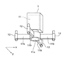
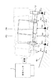
図1は本発明の第1実施の形態に係る走査型面形状測定装置の構成を模式的に示す図、図2は図1の計測ヘッド1に内蔵されている干渉計11の開口部11a周りを示す斜視図である。
【0016】
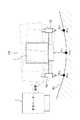
平面形状測定装置は、図1に示すように、上面に光学支持面5aが形成されている光学定盤5と、光学定盤5の光学支持面5aに置かれた被検査物4の被検面4aの面形状を得るためのデータを出力する計測ヘッド1と、計測ヘッド1が被検査物4の被検面4aを走査するように計測ヘッド1を光学定盤5の光学支持面5aと平行に移動させるための走査機構2とを備える。
【0017】
計測ヘッド1は、図2に示すように、参照面(図示せず)と被検面4a上の観測領域に対応する部分面のそれぞれからの反射光により生じる光学的干渉縞像を画像データに変換して出力する干渉計11を内蔵する。この画像データは、観測領域に対応する部分面形状を示すデータである。干渉計11には、被検面4aからの反射光を取り込むための開口部11aが形成されており、その開口部11aの周囲には、水平方向に張り出す複数のアーム11bが設けられている。各アーム11bの先端には、それぞれ、距離センサ12が取り付けられている。
【0018】
本実施の形態においては、4つのアーム11bが干渉計11の開口部11aの周りに等角度間隔で設けられており、そのうち、2つのアーム11bは、互いに開口部11aを挟んでx方向に対向するように配置されている。残り2つのアーム11bは、開口部11aを挟んでy方向に対向するように配置されている。すなわち、本実施の形態においては、4つの距離センサ12が設けられており、各距離センサ12のうち、2つの距離センサ12は、開口部11aを挟んでx方向に沿って互いに対向するように配置されている。残りの2つの距離センサ12は、開口部11aを挟んでy方向に沿って互いに対向するように配置されている。なお、アーム11bおよび距離センサ12の数、それらの配置は、上記に限定されることなくは、任意の数、任意の配置とすることが可能である。
【0019】
各距離センサ12は、それぞれの距離センサ12の位置から被検面4aまでの垂直方向高さを測定するためのセンサである。各距離センサ12としては、静電容量センサや光学式センサなど、一般的な1軸距離センサを用いることができる。ここで、上記光学式センサとしては、焦点位置検出法などを用いたものが使用される。各距離センサ12の出力は、計測ヘッド1において、被検面4aまでの垂直方向高さを示す高さデータに変換された後に出力される。
【0020】
走査機構2は、図1に示すように、門型の支持部3を有し、この支持部3は、駆動源(図示せず)を有し、光学定盤5に設けられたガイドレール2bに案内されながらy方向に自走可能に構成されている。支持部3には、上記y方向と直交するx方向に延びるガイドレール2aが設けられ、このガイドレール2aには、移動台2cが移動可能に支持されている。移動台2cは、駆動源(図示せず)を有し、この駆動源によりガイドレール2aに案内なされながらx方向に自走可能に構成されている。この走査機構2の支持部3の移動により計測ヘッド1を被検面4aに対してy方向に走査することができ、移動台2cの移動により計測ヘッド1を被検面4aに対してx方向に走査することができる。
【0021】
計測ヘッド1から出力された画像データおよび高さデータは、ケーブル6aを介して画像処理制御装置6に入力される。画像処理制御装置6は、CPU、メモリ、インタフェースなどを備える装置例えばコンピュータなどから構成される。画像処理制御装置6は、入力されたデータを解析し、被検面形状を算出する面形状算出処理を行う。この面形状算出処理の詳細については、後述する。また、画像処理制御装置6は、計測ヘッド1を走査するための走査制御を行う。この走査制御では、具体的には、移動台2c、支持部3のそれぞれに対する移動速度、移動方向、移動位置などを指示するための走査制御信号が生成され、各走査制御信号は、走査駆動部8に入力される。また、画像処理制御装置6には、モニタ7が接続されており、このモニタ7には、設定された測定条件、画像データ(干渉縞)、算出された被検面形状などを選択的に表示することが可能である。
【0022】
走査駆動部8は、画像処理制御部6から入力された各走査制御信号に基づいて、移動台2cの駆動信号と支持部3の駆動信号をそれぞれ生成する。移動台2cの駆動信号は信号線8aを介して移動台2cに出力され、支持部3の駆動信号は信号線8bを介して支持部3に出力される。
【0023】
本実施の形態においては、計測ヘッド1が予め設定されているx方向の各測定位置に順に移動するように計測ヘッド1の走査が行われる場合を例に説明する。ここで、各測定位置は、互いに隣り合う測定位置において干渉計11による観測領域の一部が重複するかまたは観測領域が接するように決定される。すなわち、互いに隣り合う測定位置は、その間隔が干渉計11の観測領域のx方向長さより狭くなるかまたは同じになるように決定される。また、測定位置の数は、干渉計11による観測領域のサイズと被検面4aの測定対象領域のサイズとに応じて決定される。
【0024】
画像処理制御装置6は、測定位置毎に干渉計11により得られた画像データに基づいて各測定位置での被検面4aの部分面形状を算出するとともに、各測定位置のうち、少なくとも1つの測定位置において距離センサ12により得られた高さデータと当該少なくとも1つの測定位置において干渉計11により得られた画像データとに基づいて仮想被検面形状を算出する。そして、この算出された仮想被検面形状を基準にして各測定位置での部分面形状を接続することによって、被検面4aの面形状が算出される。ここで、互いに隣り合う測定位置において干渉計11による観測領域の一部が重複するかまたは観測領域が接するので、互いに隣り合う部分面形状は、重複領域を有するか接することになる。
【0025】
測定位置のそれぞれにおいて得られた部分面形状を接続する際には、それぞれの部分面形状と仮想被検面形状の対応部分との残差が最小となるように、それぞれの部分面形状に対して移動、回転などの操作が行われ、操作後の各部分面形状が接続される。
【0026】
次に、被検面形状算出処理について図3ないし図8を参照しながら具体的に説明する。図3は図1の計測ヘッド1のx方向走査時における測定位置と運動誤差との一例を模式的に示す図、図4は図3の計測ヘッド1のx方向走査により得られる各測定位置での部分面形状と計測ヘッド1の走査に伴う運動誤差によって部分面形状に加算される誤差量との一例を模式的に示す図、図5は仮想被検面形状の算出に用いられる高さデータの一例を模式的に示す図、図6は算出された仮想被検面形状の一例を模式的に示す図、図7は図6の仮想被検面形状を基準にして部分面形状を補正する際の操作例を模式的に示す図、図8は図6の仮想被検面形状を基準にして補正された各部分面形状を模式的に示す図である。
【0027】
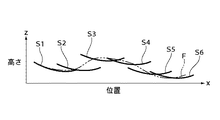
本実施の形態においては、図3に示すように、計測ヘッド1を被検面4aに対してx方向へ走査する際に、曲線Aで表される運動誤差(高さ変化およびピッチングに伴う誤差)が発生するものとする。そして、このような運動誤差が発生する場合において、5つの測定位置P1〜P5に計測ヘッド1が順に移動され、各測定位置P1〜P5で計測ヘッド1により被検面4aに対する測定が行われるものとする。ここで、高さ方向をz方向とすると、測定により得られる被検面4aの形状は実際には(x,y,z)の座標で表されるが、以下の説明においては、簡略化のために、y方向の値を一定として、測定により得られる被検面4aの形状は(x,ya=一定値,z)の座標で表すものとする。また、運動誤差の高さ変化は、z方向の変化であり、ピッチングは、計測ヘッド1をx方向に走査する場合、計測ヘッド1のy方向の中心軸周りの揺れである。
【0028】
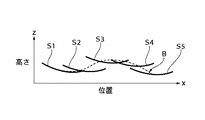
このような運動誤差が発生する場合、図4に示すように、各測定位置P1〜P5において計測ヘッド1から出力された画像データは、計測ヘッド1の走査時の運動誤差によって、図中の曲線Bで表される誤差量が加算されたものであるので、各測定位置P1〜P5での画像データから得られた被検面4aの部分面形状は、計測ヘッド1の走査時の運動誤差に応じた誤差量が含まれた形状S1〜S5となる。よって、このような誤差量が含まれている各部分面形状S1〜S5を接続する際には、それぞれの誤差量が重畳されることになり、各部分面形状を接続することによって得られる被検面形状は実際の被検面形状とは大きく異なるものになる場合がある。
【0029】
そこで、本実施の形態においては、上記運動誤差に応じた誤差量が含まれる被検面4aの部分面形状S1〜S5(各測定位置P1〜P5での画像データ)を補正するために、各測定位置P1〜P5の少なくとも1つの測定位置で各距離センサ12により得られた高さデータと当該少なくとも1つの測定位置での画像データとを用いて仮想被検面形状が算出される。そして、この算出された仮想被検面形状を基準にして部分面形状のそれぞれを接続することによって被検面形状が算出される。
【0030】
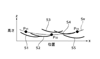
この仮想被検面形状の算出においては、図5に示すように、各測定位置P1〜P5のうち、1つの測定位置P3で各距離センサ12(x方向に沿って配置された距離センサ12)により得られた高さデータh31,h33と当該測定位置P3での画像データから求められた高さデータh32とが用いられる。ここで、1つの測定位置P3で各距離センサ12により得られた高さデータh31,h33にそれぞれ対応する被検面4a上の位置は、P31とP33とする。また、高さデータh32に対応する被検面4a上の位置は、P32(=P3)とする。
【0031】
上記位置P32(=P3)での高さデータh32を求める方法としては、具体的には、1つの測定位置P3で得られた画像データから対応する部分面形状が求められ、この部分面形状の各端の位置について、それぞれ、当該端の位置を含む所定幅の領域における高さデータ(部分面形状)を用いた最小二乗法などによって、それぞれの所定幅の領域における近似曲線が算出される。そして、位置P31とP33と部分面形状の各端の位置とがそれぞれ対応する近似曲線上にあるとすることによって、部分面形状の各端の位置とそれぞれの側にある位置P31とP33とが対応する近似曲線で接続される。これにより、測定位置P3で各距離センサ12により得られた高さデータh31,h33から測定位置P3での部分面形状の各端の位置までを接続する近似曲線で規定される形状と測定位置P3での部分面形状からなる仮想部分面形状が得られる。この仮想部分面形状の両端の高さ方向は高さデータh31,h33により規定されるので、この高さデータh31,h33と測定位置P3での画像データ(部分面形状)から、位置P32の高さデータh32を算出することが可能となる。なお、一般的には、測定可能な部分形状の高さ方向の変位(z方向の変位)の範囲は、1/2波長(約300nm)であるので、位置P32の高さデータh32を求めることができるのは、高さデータh31,h331,h32のそれぞれが微小範囲にあることが条件となる。また、画像データから部分面形状を算出する際に、位相アンラップを使用すれば、上記範囲をさらに拡大することが可能である(特開2002−131027号を参照)。
【0032】
また、上記方法においては、上記部分面形状の各端の位置のそれぞれとそれぞれの側にある位置P31とP33とが最小二乗法などによって得られた近似曲線で接続されるが、これに代えて、例えば、測定位置P3での部分面形状の各端の位置において接線方向に伸びる直線をそれぞれ算出し、位置P31とP33と部分面形状の各端の位置とがそれぞれ対応する直線上にあるとすることによって、測定位置P3で各距離センサ12により得られた高さデータh31,h33から測定位置P3での部分面形状の各端の位置までを接続する直線で規定される形状と測定位置P3での部分面形状からなる仮想部分面形状が得られる。これにより、同様に、位置P32(=P3)での高さデータh32を求めることができる。
【0033】
このようにして得られた高さデータh31,h32,h33から、図6に示すような高さデータh31,h32,h33にそれぞれに対応する位置P31,P32(=P3),P33を通る仮想被検面形状Sv(図中の二点鎖線)が算出される。この仮想被検面形状Svは、被検面4aの低次の空間周波数成分の面形状に対応するものとして見なすことができる。
【0034】
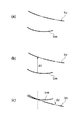
そして、各測定位置P1〜P5で得られた部分面形状S1〜S5は、それぞれ仮想被検面形状Svの対応部分と比較される。ここで、例えば図7(a)に示すように、ある部分面形状Sm(m=1〜5)と仮想被検面形状Svの対応部分とを比較することによって、図7(b)に示すような部分面形状Smと仮想被検面形状Svの対応部分との高さ方向の差d1が運動誤差の高さ変化成分として、図7(c)に示すような上記高さ方向の差d1で補正した場合の部分形状Smの仮想被検面形状Svに対する回転方向の差d2が運動誤差のピッチング変化成分として、それぞれ算出される。この算出された差d1,d2は、部分形状Smを示す値に加算された、計測ヘッド1の走査時における運動誤差に応じた誤差量に相当するものであると見なすことができる。
【0035】
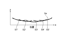
このような方法で、各部分面形状S1〜S5のそれぞれに対する差d1,d2が算出され、各部分面形状S1〜S5に対して、対応する差d1,d2のそれぞれに応じた量での高さ方向へ移動し、回転する処理が施される。これにより、図8に示すように、各部分面形状S1〜S5は、上記運動誤差により生じる誤差量が減少された面形状S1’〜S5’に補正される。そして、補正された各部分面形状S1’〜S5’を例えば平滑処理などによりそれぞれの重複領域が一致するように接続することによって、計測ヘッド1の走査時の運動誤差に応じて加算された誤差量が減少された被検面4aの形状が得られることになる。
【0036】
よって、本実施の形態によれば、観測領域が小さい干渉計11を用いて大きなサイズの被検面4aに対して高精度な面形状測定を行うことができる。換言すれば、観測領域が小さい(小口径)干渉計の横分解能を維持しながら、観測領域が大きい(大口径)干渉計を用いた測定に匹敵する測定精度を実現することが可能になる。
【0037】
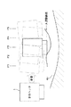
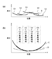
ここで、参考のために、従来の非特許文献2に示されている手法により上記各測定位置P1〜P5で得られた部分形状S1〜S5を接続する場合について図9を参照しながら説明する。図9は従来の非特許文献2に示されている手法により上記各測定位置P1〜P5で得られた部分形状S1〜S5を接続することによって得られた被検面4aの形状を模式的に示す図である。
【0038】
上記の従来の手法では、図9(a)に示すような各部分面形状S1〜S5を接続する際に、それぞれの重複領域のデータを一致させるように、各部分面形状S1〜S5が接続される。各部分面形状S1〜S5には、計測ヘッドの運動誤差(図中の曲線Bで示す)に応じた誤差量が加算されているので、このような誤差量が加算された各部分面形状S1〜S5をそれぞれの重複領域のデータが一致するように接続すると、それぞれに含まれる誤差量は重畳されて非常に大きなものとなる。よって、図9(b)に示すように、これらの部分面形状S1〜S5を接続することによって得られる被検面4aの形状(図中の曲線Cで示す)は、実際の面形状(図中の曲線Dで示す)と大きく異なるものとなる。
【0039】
これに対し、本実施の形態では、上述したように、走査時の運動誤差の影響を減少させ、観測領域が小さい干渉計11を用いて大きなサイズの被検面4aに対して高精度な面形状測定を行うことができる。
【0040】
(第2実施の形態)
次に、本発明の第2実施の形態について図10ないし図13を参照しながら説明する。図10は本発明の第2実施の形態に係る走査型面形状測定装置の計測ヘッド1のx方向走査時における測定位置と運動誤差との一例を模式的に示す図、図11は図10の計測ヘッド1のx方向走査により得られる各測定位置での部分面形状と計測ヘッド1の走査に伴う運動誤差によって部分面形状に加算される誤差量との一例を模式的に示す図、図12は本発明の第2実施の形態における仮想被検面形状算出のための推定面形状算出に用いられる高さデータの一例を模式的に示す図、図13は算出された推定面形状を接続する際の操作の一例を模式的に示す図である。
【0041】
本実施の形態においては、上記第1実施の形態に対し、測定位置毎で各距離センサ12により高さデータが検出され、それぞれの高さデータが用いられて仮想被検面形状が算出される点で異なる。また、本実施の形態は、上記第1実施の形態と同じ構成を有し、その説明ついては省略する。
【0042】
例えば、本実施の形態においては、図10に示すように、計測ヘッド1を被検面4aに対してx方向へ走査する際に、曲線Eで表される運動誤差(高さ変化およびピッチングに伴う誤差)が発生するものとする。そして、このような運動誤差が発生する場合において、6つの測定位置P1〜P6に計測ヘッド1が順に移動され、各測定位置P1〜P6で計測ヘッド1により被検面4aに対する測定が行われるものとする。
【0043】
このような運動誤差が発生する場合、図11に示すように、各測定位置P1〜P6において計測ヘッド1から出力された画像データには、計測ヘッド1の走査時の運動誤差によって、図中の曲線Fで表される誤差量が加算されるので、各測定位置P1〜P6での画像データから得られた被検面4aの部分面形状は、計測ヘッド1の走査時の運動誤差に応じた誤差量が含まれた形状S1〜S6となる。
【0044】
本実施の形態においては、上記運動誤差に応じた誤差量が含まれる被検面4aの部分面形状S1〜S6(各測定位置P1〜P6での画像データ)を補正するために、各測定位置P1〜P6で各距離センサ12により得られた高さデータと各測定位置で干渉計11により得られた画像データとを用いて仮想被検面形状が算出される。そして、この算出された仮想被検面形状を基準にして部分面形状S1〜S6のそれぞれを接続することによって被検面形状が算出される。
【0045】
具体的には、この仮想被検面形状の算出においては、まず1つの測定位置Pn(n=1〜6)における各距離センサ12(x方向に沿って配置された2つの距離センサ12)により得られた高さデータと当該測定位置Pnでの画像データから求められた高さデータとが用いられ、各高さデータにそれぞれ対応する被検面4a上の位置を通る推定形状S’nが算出される。次いで、同様に、測定位置Pnに隣接する測定位置P(n+1)で得られた各高さデータにそれぞれ対応する被検面4a上の位置を通る推定面形状S’(n+1)が算出される。そして、算出されたそれぞれの推定面形状S’n,S’(n+1)が接続される。この接続においては、推定面形状S’n,S’(n+1)間の重複領域内の形状を一致させるように推定面形状S’n,S’(n+1)に対して高さ方向への移動、回転処理などの操作が行われた後に、推定面形状S’n,S’(n+1)が接続される。他の測定位置とそれに隣接する測定位置でそれぞれ得られる推定面形状間においても、同様に、上記操作が行われ、各推定面形状が接続される。これらの接続された推定面形状から、仮想被検面形状が算出される。
【0046】
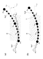
ここで、図12に示す測定位置P3と測定位置P4での推定形状を求め、それぞれの推定形状を接続する例を説明する。
【0047】
図13(a)に示すように、まず、測定位置P3での高さデータh31,h32,h33から、高さデータh31,h32,h33にそれぞれに対応する位置P31,P32(=P3),P33を通る推定面形状Sv3’が算出される。そして、測定位置P3に隣接する測定位置P4での高さデータh41,h42,h43にそれぞれに対応する位置P41,P42(=P4),P43を通る推定面形状Sv4’が算出される。
【0048】
次いで、図13(a)に示すように、測定位置P3と測定位置P4でのデータからそれぞれ得られた推定面形状Sv3’,Sv4’間の重複領域Rにおいて、それぞれの推定面形状の重複領域R内にある位置(高さ)を近似するための近似直線L3,L4が算出される。これらの近似直線L3,L4の算出には、推定面形状Sv3’,Sv4’から補間された位置(補間された高さデータ;図中の重複領域R内の白または黒の小丸で示す位置(高さデータ))および各測定位置P3,P4において干渉計11から得られた位置の高さデータが用いられる。そして、図13(b)に示すように、近似直線L3と近似直線L4を一致させるように、各推定形状Sv3’,Sv4’に対して高さ方向への移動、回転などの操作が行われ、各推定面形状Sv3’およびSv4’の接続が行われる。
【0049】
このように本実施の形態では、各測定位置で距離センサ12により検出された高さデータを用いて推定面形状がそれぞれ算出され、それぞれの推定面形状間の重複領域の形状が一致するように各推定面形状を接続することによって、仮想被検面形状Svが算出される。
【0050】
次いで、上記第1実施の形態と同様に、各測定位置P1〜P6で得られた部分面形状S1〜S6は、それぞれ仮想被検面形状Svの対応部分と比較される。この比較により、各部分面形状S1〜S6のそれぞれに対する差d1(運動誤差の高さ変化成分),d2(運動誤差のピッチング変化成分)が算出され、各部分面形状S1〜S6に対して、対応する差d1,d2のそれぞれに応じた量での高さ方向へ移動し、回転する操作が行われる。そして、補正後の各部分面形状を例えば平滑化処理などによりそれぞれの重複領域が一致するように接続することによって、計測ヘッド1の走査時の運動誤差に応じた誤差量が減少された被検面4aの形状が得られることになる。
【0051】
なお、上述した各実施の形態においては、走査時に高さ変化、ピッチングを含む運動誤差が生じる場合に、この運動誤差に応じた誤差量を減少させる例を示したが、さらにローリングなどが運動誤差に含まれる場合、干渉計11および距離センサ12のそれぞれからのデータに基づいて三次元の仮想被検面形状を算出し、この三次元の仮想被検面形状と部分面形状とを比較することによって、ローリングによる誤差量を減少させることが可能であることはいうまでもない。
【0052】
【発明の効果】
以上説明したように、本発明によれば、複数の測定位置のうち、少なくとも1つの測定位置で距離検出手段により検出された被検面上の少なくとも1つの位置との間の高さ方向の距離と該少なくとも1つの測定位置で干渉計により測定された部分面形状とに基づいて仮想被検面形状を算出し、算出された仮想被検面形状を基準にして複数の測定位置でそれぞれ測定された部分面形状を接続することによって、被検面の形状を算出するので、走査時の運動誤差の影響を減少させ、観測領域が小さい干渉計を用いて大きなサイズの被検面に対して高精度な面形状測定を行うことができる。
【図面の簡単な説明】
【図1】本発明の第1実施の形態に係る走査型面形状測定装置の構成を模式的に示す図である。
【図2】図1の計測ヘッド1に内蔵されている干渉計11の開口部11a周りを示す斜視図である。
【図3】図1の計測ヘッド1のx方向走査時における測定位置と運動誤差との一例を模式的に示す図である。
【図4】図3の計測ヘッド1のx方向走査により得られる各測定位置での部分面形状と計測ヘッド1の走査に伴う運動誤差によって部分面形状に加算される誤差量との一例を模式的に示す図である。
【図5】仮想被検面形状の算出に用いられる高さデータの一例を模式的に示す図である。
【図6】算出された仮想被検面形状の一例を模式的に示す図である。
【図7】図6の仮想被検面形状を基準にして部分面形状を補正する際の操作例を模式的に示す図である。
【図8】図6の仮想被検面形状を基準にして補正された各部分面形状を模式的に示す図である。
【図9】従来の非特許文献2に示されている手法により上記各測定位置P1〜P5で得られた部分形状S1〜S5を接続することによって得られた被検面4aの形状を模式的に示す図である。
【図10】本発明の第2実施の形態に係る走査型面形状測定装置の計測ヘッド1のx方向走査時における測定位置と運動誤差との一例を模式的に示す図である。
【図11】図10の計測ヘッド1のx方向走査により得られる各測定位置での部分面形状と計測ヘッド1の走査に伴う運動誤差によって部分面形状に加算される誤差量との一例を模式的に示す図である。
【図12】本発明の第2実施の形態における仮想被検面形状算出のための推定面形状算出に用いられる高さデータの一例を模式的に示す図である。
【図13】算出された推定面形状を接続する際の操作の一例を模式的に示す図である。
【符号の説明】
1 計測ヘッド
2 走査機構
4a 被検面
6 画像処理制御装置
7 モニタ
8 走査駆動部
11 干渉計
11a 開口部
12 距離センサ[0001]
BACKGROUND OF THE INVENTION
The present invention relates to a scanning surface shape measuring apparatus and a surface shape measuring method for measuring the shape of a test surface by scanning the test surface with an interferometer.
[0002]
[Prior art]
One apparatus for measuring the planar shape with high accuracy is an interferometer. The interferometer generates interference fringes from the reflected light from the reference surface and the reflected light from the test surface, and measures the shape of the test surface based on the interference fringes, and observes the laser light. The optical system projects an enlarged image onto an area, the optical system forms an image of interference fringes generated during measurement, and an image sensor such as a CCD that converts the formed interference fringe image into an electrical signal. The observation area and lateral resolution of the interferometer are determined by the optical design and the number of pixels of the image sensor. In the interferometer, when the observation area is increased, the lateral resolution is lowered, and conversely, when the lateral resolution is increased, the observation area is reduced. Therefore, it is necessary to individually select the interferometer according to the size of the surface to be measured and the lateral resolution at the time of measurement. Furthermore, in an interferometer having a large observation area, since the optical parts to be used are large, the apparatus size tends to be large and the price tends to be expensive.
[0003]
As a method of measuring the shape of a large test surface using an interferometer having a small observation area, there is a method of measuring the shape of the test surface by scanning the interferometer with respect to the test surface. In the case of this method, in order to perform highly accurate surface shape measurement on the surface to be measured, it is required to perform ideal scanning so that the motion error during scanning is extremely small. In addition, as described in the Journal of Precision Engineering Vol.61, No.12,1995 “Study on Ultra-Smooth Polishing Technology for Aspherical Optical Elements (1st Report) -Development of On-Machine Shape Measuring Device-” There is a method of correcting and correcting the motion error with high accuracy.
[0004]
Further, in the measurement method of measuring the test surface shape by scanning the test surface with the interferometer, a method for measuring the test surface shape without being affected by the movement error at the time of scanning, It is proposed in “Measurement of large plane surface shape by connecting small-aperture interferograms” (Optical engineering Feb., 1994, Vol.33, No.2, (608)). This method calculates the shape of the entire test surface by scanning the interferometer while overlapping the observation region with respect to the test surface, and connecting the shape of each region obtained from each observation region. is there. Here, when connecting the calculated shapes of the adjacent regions, the slope component of the shape of each region is corrected so that the data of the overlapping regions in the shape of each region match. However, this method requires sufficiently high measurement accuracy for each observation region.
[0005]
[Non-Patent Document 1]
Journal of Japan Society for Precision Engineering Vol.61, No.12,1995 "Study on ultra-smooth polishing technology for aspherical optical elements (1st report) -Development of on-machine shape measuring device-"
[Non-Patent Document 2]
“Measurement of large plane surface shape by connecting small-aperture interferograms” (Optical engineering Feb., 1994, Vol.33, No.2, (608))
[0006]
[Problems to be solved by the invention]
However, in the case of the measurement method in which the interferometer is scanned with respect to the above-described test surface, it is possible to realize a scanning mechanism capable of performing an ideal scan so that a motion error during scanning becomes very small. In addition, in the case of a method for correcting and correcting the motion error with high accuracy in advance, it is very difficult to correct the motion error during scanning with high accuracy.
[0007]
In addition, in the case of a method for measuring the shape of the surface to be measured without being affected by motion errors, a sufficiently high measurement accuracy is required for each observation region, but it is possible to achieve the measurement accuracy as required. At present, it is difficult, and there is an error larger than the error corresponding to the required measurement accuracy in the shape calculated from each observation region. As a result, when connecting the calculated shape of each region, each error is accumulated and becomes very large, and it is difficult to obtain the shape of the test surface with sufficiently high measurement accuracy. Conceivable.
[0008]
The present invention has been made to solve the above-described problems, and reduces the influence of motion error during scanning, and has a highly accurate surface shape with respect to a large test surface using an interferometer with a small observation area. An object of the present invention is to provide a scanning surface shape measuring apparatus and a surface shape measuring method capable of performing measurement.
[0009]
[Means for Solving the Problems]
In order to achieve the above object, the present invention provides a partial surface shape corresponding to the observation region based on interference fringes generated by reflected light from each of the partial surface corresponding to the observation region on the surface to be measured and the reference surface. A distance detecting means for detecting a distance in the height direction between the interferometer to be measured and at least one position on the test surface; and a mounting portion for mounting the interferometer and the distance detecting means. Scanning means for moving the mounting portion relative to the surface to be measured so that the observation region of the interferometer is at least in contact with adjacent measurement positions in order to a plurality of measurement positions; and Among them, the distance in the height direction between the at least one measurement position detected by the distance detection means and the at least one position on the surface to be measured and the at least one measurement position measured by the interferometer Partial surface shape A virtual test surface shape based on the calculated virtual test surface shape, and connecting the partial surface shapes measured at the plurality of measurement positions with reference to the calculated virtual test surface shape. And a surface shape calculating means for calculating the shape.
[0010]
Further, the surface shape calculating means corrects each of the partial surface shapes so that a residual with the corresponding portion of the virtual test surface shape is minimized, and connects the corrected partial surface shapes respectively. It is characterized by.
[0011]
Further, the distance detection means detects distances in the height direction between a plurality of different positions on the test surface, and the surface shape calculation means calculates the virtual test surface shape by calculating the virtual test surface shape. A distance in the height direction between a plurality of different positions on the surface to be detected, each detected by a distance detecting means, is used.
[0012]
Further, the distance detecting means detects a distance in the height direction between at least one position outside the observation region on the surface to be measured.
[0013]
In order to achieve the above object, the present invention provides a partial surface corresponding to the observation region based on interference fringes generated by reflected light from each of the partial surface corresponding to the observation region on the surface to be measured and the reference surface. A mounting portion on which a distance detecting means for detecting a distance in the height direction between the interferometer for measuring the shape and at least one position on the surface to be measured is mounted in order to a plurality of measurement positions. A surface shape measuring method for measuring a surface shape of the test surface by moving the relative position with respect to the test surface so that the observation region of the interferometer is at least in contact with the measurement position, Among the measurement positions, the distance in the height direction between at least one measurement position detected by the distance detection means and the at least one position on the surface to be measured and the interferometer at the at least one measurement position Measured by By calculating the virtual test surface shape based on the calculated partial surface shape, by connecting the partial surface shapes respectively measured at the plurality of measurement positions with reference to the calculated virtual test surface shape, The shape of the test surface is calculated.
[0014]
DETAILED DESCRIPTION OF THE INVENTION
Hereinafter, embodiments of the present invention will be described with reference to the drawings.
[0015]
(First embodiment)
FIG. 1 is a diagram schematically showing the configuration of a scanning surface shape measuring apparatus according to a first embodiment of the present invention. FIG. 2 is a view around an opening 11a of an
[0016]
As shown in FIG. 1, the planar shape measuring apparatus includes an
[0017]
As shown in FIG. 2, the measuring
[0018]
In the present embodiment, four
[0019]
Each
[0020]
As shown in FIG. 1, the
[0021]
The image data and height data output from the measuring
[0022]
The scanning drive unit 8 generates a driving signal for the movable table 2 c and a driving signal for the
[0023]
In the present embodiment, an example will be described in which the
[0024]
The image processing control device 6 calculates the partial surface shape of the
[0025]
When connecting the partial surface shapes obtained at each of the measurement positions, each partial surface shape is set so that the residual between each partial surface shape and the corresponding portion of the virtual test surface shape is minimized. Thus, operations such as movement and rotation are performed, and the partial surface shapes after the operation are connected.
[0026]
Next, the test surface shape calculation process will be specifically described with reference to FIGS. FIG. 3 is a diagram schematically showing an example of the measurement position and the movement error when the
[0027]
In the present embodiment, as shown in FIG. 3, when the measuring
[0028]
When such a movement error occurs, as shown in FIG. 4, the image data output from the
[0029]
Therefore, in the present embodiment, in order to correct the partial surface shapes S1 to S5 (image data at the respective measurement positions P1 to P5) of the
[0030]
In the calculation of the virtual test surface shape, as shown in FIG. 5, each distance sensor 12 (
[0031]
Above position P 32 Height data h at (= P3) 32 Specifically, the corresponding partial surface shape is obtained from the image data obtained at one measurement position P3, and the position of each end of the partial surface shape is determined for each end position. An approximate curve in each region having a predetermined width is calculated by a least square method using height data (partial surface shape) in a region having a predetermined width. And position P 31 And P 33 And the position of each end of the partial surface shape are on the corresponding approximate curves, respectively, so that the position of each end of the partial surface shape and the position P on each side 31 And P 33 Are connected by a corresponding approximate curve. Thereby, the height data h obtained by each
[0032]
In the above method, the position of each end of the partial surface shape and the position P on each side 31 And P 33 Are connected by an approximate curve obtained by the least square method or the like, but instead, for example, straight lines extending in the tangential direction at the positions of the ends of the partial surface shape at the measurement position P3 are calculated, P 31 And P 33 Height data h obtained by each
[0033]
The height data h thus obtained 31 , H 32 , H 33 To height data h as shown in FIG. 31 , H 32 , H 33 P corresponding to each 31 , P 32 (= P3), P 33 A virtual test surface shape Sv passing through (two-dot chain line in the figure) is calculated. This virtual test surface shape Sv can be regarded as corresponding to the surface shape of the low-order spatial frequency component of the
[0034]
Then, the partial surface shapes S1 to S5 obtained at the respective measurement positions P1 to P5 are respectively compared with the corresponding portions of the virtual test surface shape Sv. Here, for example, as shown in FIG. 7A, by comparing a partial surface shape Sm (m = 1 to 5) with a corresponding portion of the virtual test surface shape Sv, it is shown in FIG. 7B. The difference d1 in the height direction between the corresponding partial surface shape Sm and the corresponding portion of the virtual test surface shape Sv is the difference in height d1 as shown in FIG. The difference d2 in the rotation direction of the partial shape Sm with respect to the virtual test surface shape Sv in the case of correction in (5) is calculated as a pitching change component of the motion error. The calculated differences d1 and d2 can be regarded as corresponding to an error amount corresponding to a motion error at the time of scanning of the measuring
[0035]
In this way, the differences d1 and d2 for each of the partial surface shapes S1 to S5 are calculated, and for each of the partial surface shapes S1 to S5, a high amount corresponding to each of the corresponding differences d1 and d2 is obtained. A process of moving in the vertical direction and rotating is performed. As a result, as shown in FIG. 8, the partial surface shapes S1 to S5 are corrected to the surface shapes S1 ′ to S5 ′ in which the amount of error caused by the motion error is reduced. Then, the corrected partial surface shapes S1 ′ to S5 ′ are connected so that the overlapping regions thereof coincide with each other by, for example, smoothing processing, thereby adding an error added according to the motion error at the time of scanning of the measuring
[0036]
Therefore, according to the present embodiment, it is possible to perform highly accurate surface shape measurement on the large-
[0037]
Here, for reference, a case where the partial shapes S1 to S5 obtained at the measurement positions P1 to P5 are connected by the method shown in the conventional
[0038]
In the conventional method described above, when connecting the partial surface shapes S1 to S5 as shown in FIG. 9A, the partial surface shapes S1 to S5 are connected so that the data of the respective overlapping regions are matched. Is done. Since each partial surface shape S1 to S5 is added with an error amount corresponding to the movement error (indicated by curve B in the drawing) of the measuring head, each partial surface shape S1 to which such an error amount is added. When .about.S5 are connected so that the data of the respective overlapping areas match, the error amounts included in each overlap are superposed and become very large. Therefore, as shown in FIG. 9B, the shape of the
[0039]
On the other hand, in the present embodiment, as described above, the influence of the motion error during scanning is reduced, and a high-accuracy surface with respect to a large-
[0040]
(Second Embodiment)
Next, a second embodiment of the present invention will be described with reference to FIGS. FIG. 10 is a diagram schematically showing an example of a measurement position and a movement error during scanning in the x direction of the measuring
[0041]
In the present embodiment, height data is detected by each
[0042]
For example, in the present embodiment, as shown in FIG. 10, when the measuring
[0043]
When such a motion error occurs, as shown in FIG. 11, the image data output from the
[0044]
In the present embodiment, in order to correct the partial surface shapes S1 to S6 (image data at each measurement position P1 to P6) of the
[0045]
Specifically, in the calculation of the virtual test surface shape, first, each distance sensor 12 (two
[0046]
Here, an example in which estimated shapes at the measurement position P3 and the measurement position P4 shown in FIG. 12 are obtained and the respective estimated shapes are connected will be described.
[0047]
As shown in FIG. 13A, first, height data h at the measurement position P3. 31 , H 32 , H 33 To height data h 31 , H 32 , H 33 P corresponding to each 31 , P 32 (= P3), P 33 An estimated surface shape Sv3 ′ passing through is calculated. And the height data h at the measurement position P4 adjacent to the measurement position P3 41 , H 42 , H 43 P corresponding to each 41 , P 42 (= P4), P 43 An estimated surface shape Sv4 ′ passing through is calculated.
[0048]
Next, as shown in FIG. 13A, in the overlapping region R between the estimated surface shapes Sv3 ′ and Sv4 ′ obtained from the data at the measurement position P3 and the measurement position P4, the overlapping regions of the respective estimated surface shapes. Approximate straight lines L3 and L4 for approximating the position (height) in R are calculated. For calculating these approximate straight lines L3 and L4, positions interpolated from the estimated surface shapes Sv3 ′ and Sv4 ′ (interpolated height data; positions indicated by white or black small circles in the overlapping region R in the figure ( Height data)) and the height data of the positions obtained from the
[0049]
As described above, in this embodiment, the estimated surface shapes are calculated using the height data detected by the
[0050]
Next, as in the first embodiment, the partial surface shapes S1 to S6 obtained at the measurement positions P1 to P6 are compared with corresponding portions of the virtual test surface shape Sv, respectively. By this comparison, a difference d1 (motion error height change component) and d2 (motion error pitching change component) for each of the partial surface shapes S1 to S6 is calculated, and for each partial surface shape S1 to S6, An operation of moving and rotating in the height direction by an amount corresponding to each of the corresponding differences d1 and d2 is performed. Then, the corrected partial surface shapes are connected so that their overlapping areas coincide with each other by, for example, smoothing processing, etc., so that the amount of error corresponding to the movement error during scanning of the measuring
[0051]
In each of the above-described embodiments, an example in which an error amount corresponding to the motion error is reduced when a motion error including a height change and pitching occurs during scanning has been described. The three-dimensional virtual test surface shape is calculated based on the data from each of the
[0052]
【The invention's effect】
As described above, according to the present invention, the distance in the height direction between at least one position on the surface to be measured detected by the distance detecting means at at least one of the plurality of measurement positions. And a virtual test surface shape calculated based on the partial surface shape measured by the interferometer at the at least one measurement position and measured at a plurality of measurement positions based on the calculated virtual test surface shape. Since the shape of the test surface is calculated by connecting the partial surface shapes, the influence of motion errors during scanning is reduced, and an interferometer with a small observation area is used to increase the size of the test surface. Accurate surface shape measurement can be performed.
[Brief description of the drawings]
FIG. 1 is a diagram schematically showing a configuration of a scanning surface shape measuring apparatus according to a first embodiment of the present invention.
2 is a perspective view showing the periphery of an
FIG. 3 is a diagram schematically illustrating an example of a measurement position and a motion error when the
4 is a schematic diagram illustrating an example of a partial surface shape at each measurement position obtained by scanning in the x direction of the
FIG. 5 is a diagram schematically illustrating an example of height data used for calculation of a virtual test surface shape.
FIG. 6 is a diagram schematically illustrating an example of a calculated virtual test surface shape.
7 is a diagram schematically showing an operation example when correcting the partial surface shape based on the virtual test surface shape of FIG. 6; FIG.
8 is a diagram schematically showing each partial surface shape corrected with reference to the virtual test surface shape in FIG. 6; FIG.
FIG. 9 schematically shows the shape of the
FIG. 10 is a diagram schematically illustrating an example of a measurement position and a movement error when the measuring
11 is a schematic diagram illustrating an example of a partial surface shape at each measurement position obtained by scanning in the x direction of the
FIG. 12 is a diagram schematically illustrating an example of height data used for estimation surface shape calculation for virtual test surface shape calculation in the second exemplary embodiment of the present invention.
FIG. 13 is a diagram schematically illustrating an example of an operation for connecting a calculated estimated surface shape.
[Explanation of symbols]
1 Measuring head
2 Scanning mechanism
4a Test surface
6 Image processing control device
7 Monitor
8 Scanning drive
11 Interferometer
11a opening
12 Distance sensor
Claims (8)
前記被検面上の少なくとも1つの位置との間の高さ方向の距離を検出する距離検出手段と、
前記干渉計と前記距離検出手段とを搭載する搭載部を有し、前記搭載部を複数の測定位置へ順に、隣り合う測定位置で前記干渉計の前記観測領域が少なくとも接するように、前記被検面に対して相対移動させる走査手段と、
前記複数の測定位置のうち、少なくとも1つの測定位置で前記距離検出手段により検出された前記被検面上の少なくとも1つの位置との間の高さ方向の距離と該少なくとも1つの測定位置で前記干渉計により測定された部分面形状とに基づいて仮想被検面形状を算出し、該算出された仮想被検面形状を基準にして前記複数の測定位置でそれぞれ測定された部分面形状を接続することによって、前記被検面の形状を算出する面形状算出手段とを備えることを特徴とする走査型面形状測定装置。An interferometer that measures a partial surface shape corresponding to the observation region based on interference fringes generated by reflected light from each of the partial surface and the reference surface corresponding to the observation region on the test surface;
A distance detecting means for detecting a distance in a height direction between at least one position on the test surface;
A mounting portion on which the interferometer and the distance detecting means are mounted, and the mounting portion is sequentially moved to a plurality of measurement positions so that the observation region of the interferometer is in contact with at least adjacent measurement positions. Scanning means for moving relative to the surface;
Of the plurality of measurement positions, the distance in the height direction between at least one position on the test surface detected by the distance detection means at at least one measurement position and the at least one measurement position at the at least one measurement position. Calculate the virtual test surface shape based on the partial surface shape measured by the interferometer, and connect the partial surface shapes measured at each of the plurality of measurement positions based on the calculated virtual test surface shape A scanning surface shape measuring apparatus comprising: a surface shape calculating means for calculating the shape of the test surface.
前記複数の測定位置のうち、少なくとも1つの測定位置で前記距離検出手段により検出された前記被検面上の少なくとも1つの位置との間の高さ方向の距離と該少なくとも1つの測定位置で前記干渉計により測定された部分面形状とに基づいて仮想被検面形状を算出し、
前記算出された仮想被検面形状を基準にして前記複数の測定位置でそれぞれ測定された部分面形状を接続することによって、前記被検面の形状を算出することを特徴とする面形状測定方法。An interferometer for measuring a partial surface shape corresponding to the observation region based on interference fringes generated by reflected light from the partial surface corresponding to the observation region on the test surface and the reference surface, and the test surface A mounting unit on which a distance detection unit that detects a distance in the height direction between at least one position is mounted in order to a plurality of measurement positions, and the observation region of the interferometer is at least at adjacent measurement positions. A surface shape measuring method for measuring the surface shape of the test surface by moving relative to the test surface so as to come into contact with the test surface,
Of the plurality of measurement positions, the distance in the height direction between at least one position on the test surface detected by the distance detection means at at least one measurement position and the at least one measurement position at the at least one measurement position. Calculate the virtual test surface shape based on the partial surface shape measured by the interferometer,
A surface shape measuring method comprising: calculating a shape of the test surface by connecting partial surface shapes respectively measured at the plurality of measurement positions on the basis of the calculated virtual test surface shape .
Priority Applications (1)
| Application Number | Priority Date | Filing Date | Title |
|---|---|---|---|
| JP2003206673A JP4183576B2 (en) | 2003-08-08 | 2003-08-08 | Scanning surface shape measuring apparatus and surface shape measuring method |
Applications Claiming Priority (1)
| Application Number | Priority Date | Filing Date | Title |
|---|---|---|---|
| JP2003206673A JP4183576B2 (en) | 2003-08-08 | 2003-08-08 | Scanning surface shape measuring apparatus and surface shape measuring method |
Publications (2)
| Publication Number | Publication Date |
|---|---|
| JP2005055221A JP2005055221A (en) | 2005-03-03 |
| JP4183576B2 true JP4183576B2 (en) | 2008-11-19 |
Family
ID=34363448
Family Applications (1)
| Application Number | Title | Priority Date | Filing Date |
|---|---|---|---|
| JP2003206673A Expired - Fee Related JP4183576B2 (en) | 2003-08-08 | 2003-08-08 | Scanning surface shape measuring apparatus and surface shape measuring method |
Country Status (1)
| Country | Link |
|---|---|
| JP (1) | JP4183576B2 (en) |
Families Citing this family (7)
| Publication number | Priority date | Publication date | Assignee | Title |
|---|---|---|---|---|
| JP4505318B2 (en) * | 2004-11-30 | 2010-07-21 | ワイエムシステムズ株式会社 | Three-dimensional shape measuring apparatus, three-dimensional shape measuring method, and three-dimensional shape measuring program |
| DE102005043912B4 (en) * | 2005-05-18 | 2011-08-18 | Steinbichler Optotechnik GmbH, 83115 | Method for determining the 3D coordinates of the surface of an object |
| JP4677613B2 (en) * | 2006-05-08 | 2011-04-27 | コニカミノルタセンシング株式会社 | 3D shape measurement system |
| JP5070370B2 (en) * | 2007-05-23 | 2012-11-14 | 株式会社ジェイテック | Ultraprecision shape measuring method and apparatus |
| US8334985B2 (en) * | 2010-10-08 | 2012-12-18 | Omron Corporation | Shape measuring apparatus and shape measuring method |
| JP5698963B2 (en) * | 2010-11-22 | 2015-04-08 | 株式会社小坂研究所 | Surface shape measurement method |
| DE102015209117A1 (en) * | 2014-06-05 | 2015-12-10 | Dr. Johannes Heidenhain Gmbh | Interferential position measuring device and method for operating an interferential position measuring device |
-
2003
- 2003-08-08 JP JP2003206673A patent/JP4183576B2/en not_active Expired - Fee Related
Also Published As
| Publication number | Publication date |
|---|---|
| JP2005055221A (en) | 2005-03-03 |
Similar Documents
| Publication | Publication Date | Title |
|---|---|---|
| JP3946499B2 (en) | Method for detecting posture of object to be observed and apparatus using the same | |
| KR101629545B1 (en) | Shape measuring device, shape measuring method, structure manufacturing method, and program | |
| JP4939304B2 (en) | Method and apparatus for measuring film thickness of transparent film | |
| US20130197844A1 (en) | Measurement apparatus | |
| JP2002162205A (en) | Method for detecting and correcting analytical error of striped image | |
| JP5663758B2 (en) | Shape measuring method and shape measuring apparatus | |
| JP4183576B2 (en) | Scanning surface shape measuring apparatus and surface shape measuring method | |
| US7443516B2 (en) | Optical-distortion correcting apparatus and optical-distortion correcting method | |
| JP5057848B2 (en) | Method and apparatus for measuring refractive index of transparent film and method and apparatus for measuring film thickness of transparent film | |
| JP4791568B2 (en) | 3D measuring device | |
| JP5649926B2 (en) | Surface shape measuring apparatus and surface shape measuring method | |
| JP5290038B2 (en) | Measuring apparatus and measuring method | |
| JPH11351840A (en) | Noncontact type three-dimensional measuring method | |
| JP5955001B2 (en) | Aspherical shape measurement method, shape measurement program, and shape measurement device | |
| JP6386954B2 (en) | Surface shape measuring apparatus and surface shape measuring method | |
| JP2005172610A (en) | Three-dimensional measurement apparatus | |
| JP2009041983A (en) | Method for detecting variation of zero-point error of multi-point probe | |
| JP2005127805A (en) | Planar shape measuring method and system | |
| JP4638077B2 (en) | Scanning wide area shape analyzer for test surface | |
| CN114111638B (en) | Curved surface detection method based on phase deflection | |
| JP2003057191A (en) | Apparatus for measuring shape of cylindrical article to be measured and method of adjusting the apparatus for measuring shape of cylindrical article to be measured, as well as method for processing signal | |
| JP3863408B2 (en) | Magnetic head slider inspection device | |
| JPH01153908A (en) | Three-dimensional measuring instrument | |
| JPH10332350A (en) | Shape measuring method using interferometer | |
| JP5226602B2 (en) | Three-dimensional shape measurement method |
Legal Events
| Date | Code | Title | Description |
|---|---|---|---|
| RD03 | Notification of appointment of power of attorney |
Free format text: JAPANESE INTERMEDIATE CODE: A7423 Effective date: 20060426 |
|
| A621 | Written request for application examination |
Free format text: JAPANESE INTERMEDIATE CODE: A621 Effective date: 20060710 |
|
| A977 | Report on retrieval |
Free format text: JAPANESE INTERMEDIATE CODE: A971007 Effective date: 20080507 |
|
| TRDD | Decision of grant or rejection written | ||
| A01 | Written decision to grant a patent or to grant a registration (utility model) |
Free format text: JAPANESE INTERMEDIATE CODE: A01 Effective date: 20080826 |
|
| A01 | Written decision to grant a patent or to grant a registration (utility model) |
Free format text: JAPANESE INTERMEDIATE CODE: A01 |
|
| A61 | First payment of annual fees (during grant procedure) |
Free format text: JAPANESE INTERMEDIATE CODE: A61 Effective date: 20080902 |
|
| FPAY | Renewal fee payment (event date is renewal date of database) |
Free format text: PAYMENT UNTIL: 20110912 Year of fee payment: 3 |
|
| R150 | Certificate of patent or registration of utility model |
Ref document number: 4183576 Country of ref document: JP Free format text: JAPANESE INTERMEDIATE CODE: R150 Free format text: JAPANESE INTERMEDIATE CODE: R150 |
|
| FPAY | Renewal fee payment (event date is renewal date of database) |
Free format text: PAYMENT UNTIL: 20140912 Year of fee payment: 6 |
|
| R250 | Receipt of annual fees |
Free format text: JAPANESE INTERMEDIATE CODE: R250 |
|
| R250 | Receipt of annual fees |
Free format text: JAPANESE INTERMEDIATE CODE: R250 |
|
| R250 | Receipt of annual fees |
Free format text: JAPANESE INTERMEDIATE CODE: R250 |
|
| R250 | Receipt of annual fees |
Free format text: JAPANESE INTERMEDIATE CODE: R250 |
|
| LAPS | Cancellation because of no payment of annual fees |