JP4175697B2 - Glass substrate holder - Google Patents
Glass substrate holder Download PDFInfo
- Publication number
- JP4175697B2 JP4175697B2 JP17157098A JP17157098A JP4175697B2 JP 4175697 B2 JP4175697 B2 JP 4175697B2 JP 17157098 A JP17157098 A JP 17157098A JP 17157098 A JP17157098 A JP 17157098A JP 4175697 B2 JP4175697 B2 JP 4175697B2
- Authority
- JP
- Japan
- Prior art keywords
- glass substrate
- support pin
- support
- substrate holder
- holding frame
- Prior art date
- Legal status (The legal status is an assumption and is not a legal conclusion. Google has not performed a legal analysis and makes no representation as to the accuracy of the status listed.)
- Expired - Fee Related
Links
- 239000000758 substrate Substances 0.000 title claims description 73
- 239000011521 glass Substances 0.000 title claims description 65
- 238000005286 illumination Methods 0.000 claims description 15
- 230000002093 peripheral effect Effects 0.000 claims description 3
- 239000004809 Teflon Substances 0.000 description 19
- 229920006362 Teflon® Polymers 0.000 description 19
- 239000006121 base glass Substances 0.000 description 13
- 230000005540 biological transmission Effects 0.000 description 7
- 238000005452 bending Methods 0.000 description 6
- NJPPVKZQTLUDBO-UHFFFAOYSA-N novaluron Chemical compound C1=C(Cl)C(OC(F)(F)C(OC(F)(F)F)F)=CC=C1NC(=O)NC(=O)C1=C(F)C=CC=C1F NJPPVKZQTLUDBO-UHFFFAOYSA-N 0.000 description 5
- 238000007689 inspection Methods 0.000 description 4
- 230000004048 modification Effects 0.000 description 4
- 238000012986 modification Methods 0.000 description 4
- 230000000694 effects Effects 0.000 description 3
- 239000004973 liquid crystal related substance Substances 0.000 description 2
- 238000000034 method Methods 0.000 description 2
- 239000012780 transparent material Substances 0.000 description 2
- PYVHTIWHNXTVPF-UHFFFAOYSA-N F.F.F.F.C=C Chemical compound F.F.F.F.C=C PYVHTIWHNXTVPF-UHFFFAOYSA-N 0.000 description 1
- 210000001015 abdomen Anatomy 0.000 description 1
- 230000006835 compression Effects 0.000 description 1
- 238000007906 compression Methods 0.000 description 1
- 229920006351 engineering plastic Polymers 0.000 description 1
- 238000004519 manufacturing process Methods 0.000 description 1
- 239000000463 material Substances 0.000 description 1
- 239000002184 metal Substances 0.000 description 1
- 229920003023 plastic Polymers 0.000 description 1
- 229920006122 polyamide resin Polymers 0.000 description 1
- 229920005668 polycarbonate resin Polymers 0.000 description 1
- 239000004431 polycarbonate resin Substances 0.000 description 1
- 238000003825 pressing Methods 0.000 description 1
- 238000005096 rolling process Methods 0.000 description 1
- 238000004088 simulation Methods 0.000 description 1
- 125000006850 spacer group Chemical group 0.000 description 1
- 239000005341 toughened glass Substances 0.000 description 1
- 238000002834 transmittance Methods 0.000 description 1
Images

Classifications
-
- B—PERFORMING OPERATIONS; TRANSPORTING
- B65—CONVEYING; PACKING; STORING; HANDLING THIN OR FILAMENTARY MATERIAL
- B65G—TRANSPORT OR STORAGE DEVICES, e.g. CONVEYORS FOR LOADING OR TIPPING, SHOP CONVEYOR SYSTEMS OR PNEUMATIC TUBE CONVEYORS
- B65G49/00—Conveying systems characterised by their application for specified purposes not otherwise provided for
- B65G49/05—Conveying systems characterised by their application for specified purposes not otherwise provided for for fragile or damageable materials or articles
- B65G49/06—Conveying systems characterised by their application for specified purposes not otherwise provided for for fragile or damageable materials or articles for fragile sheets, e.g. glass
- B65G49/061—Lifting, gripping, or carrying means, for one or more sheets forming independent means of transport, e.g. suction cups, transport frames
-
- B—PERFORMING OPERATIONS; TRANSPORTING
- B65—CONVEYING; PACKING; STORING; HANDLING THIN OR FILAMENTARY MATERIAL
- B65G—TRANSPORT OR STORAGE DEVICES, e.g. CONVEYORS FOR LOADING OR TIPPING, SHOP CONVEYOR SYSTEMS OR PNEUMATIC TUBE CONVEYORS
- B65G2249/00—Aspects relating to conveying systems for the manufacture of fragile sheets
- B65G2249/02—Controlled or contamination-free environments or clean space conditions
-
- B—PERFORMING OPERATIONS; TRANSPORTING
- B65—CONVEYING; PACKING; STORING; HANDLING THIN OR FILAMENTARY MATERIAL
- B65G—TRANSPORT OR STORAGE DEVICES, e.g. CONVEYORS FOR LOADING OR TIPPING, SHOP CONVEYOR SYSTEMS OR PNEUMATIC TUBE CONVEYORS
- B65G2249/00—Aspects relating to conveying systems for the manufacture of fragile sheets
- B65G2249/04—Arrangements of vacuum systems or suction cups
Landscapes
- Liquid Crystal (AREA)
- Container, Conveyance, Adherence, Positioning, Of Wafer (AREA)
- Investigating Materials By The Use Of Optical Means Adapted For Particular Applications (AREA)
Description
【0001】
【発明の属する技術分野】
本発明は、液晶ガラス基板を製造、検査する際にガラス基板を保持するための保持具に関する。
【0002】
【従来の技術】
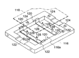
従来、液晶ガラス基板などの大型のガラス基板を保持する保持具には、「基板ホルダ」として、特開平9−189641号公報所載の技術が開示されている。図6を用いて、この技術を説明する。基板ホルダ116は、ガラス基板118を所定の位置に吸着保持させる吸着保持機構と、ガラス基板118を損傷させることなくガラス基板118に生じる撓みや振動を除去するように、ガラス基板118の一部を支持可能な支持機構とを備える。吸着保持機構は、ガラス基板118を基板ホルダ116上に吸着させる吸着機構120と、ガラス基板118を当て付けピン122方向に押圧して所定位置に位置付け保持させる押付ピン124とを備える。支持機構は、透過照明光開口116aを横断するように配置された一対の透明板126と、これら透明板上に夫々突設された透明材料からなる一対の支持ピン128を昇降させることによって、一対の支持ピン128をガラス基板118の裏面に対して当接および離間させる昇降装置とを備えるものである。
【0003】
【発明が解決しようとする課題】
しかるに、上記従来技術には、つぎのような問題点があった。すなわち、最近のガラス基板はますます大型化の傾向にあり、厚さ0.7〜1.1mmで、幅および長さはほぼ1mに達するものもあるため、上記基板ホルダの支持ピン128を4個所配置した一対の透明板126によってガラス基板118を支持する構造では、透明板126の剛性が低いため、ガラス基板118の重量によって撓みや振動が発生し、ガラス基板118の表面の傷や汚れを基板検査装置によって発見することは困難であった。
【0004】
本発明は、上記従来の問題点に鑑みてなされたもので、本発明の課題は、ガラス基板の平面度を保持し、基板表面を傷つけることがなく、撓みや振動の発生を抑えることができるガラス基板保持具を提供することである。
【0005】
【課題を解決するための手段】
上記課題を解決するために、本願発明のガラス基板保持具は、矩形状のガラス基板の周縁部を載置する矩形状開口部を形成した保持枠と、前記保持枠の開口部の下部を閉塞するように全周を前記保持枠に固定され、透過照明光を透過する透明部材からなる台部材と、前記台部材の上面に複数配置され前記ガラス基板を水平に支持する支持ピンと、を備えた。
【0006】
本願発明のガラス基板保持具は、保持枠の開口部下部を閉塞するように全周を前記保持枠に固定され、透過照明光を透過す透明部材からなる台部材上に複数の支持ピンを配置してガラス基板を支持することにより、ガラス基板に平面度を保持し、撓みや振動の発生を抑えることができる。
【0007】
【発明の実施の形態】
以下、具体的な実施の形態について説明する。
【0008】
(実施の形態1)
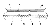
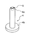
図1〜図3は実施の形態1を示し、図1はガラス基板保持具の斜視図、図2はガラス基板保持具の支持ピン付近の縦断面図、図3は支持ピンの斜視図である。
【0009】
図1および図2において、ガラス基板保持具は、例えば基板検査装置のステージ(図示省略)により水平方向に移動し、透過照明装置(図示省略)の上方に位置するように配設されている。ガラス基板保持具の保持枠1には、透過照明用開口1aが形成され、透過照明装置から照射される照明光によって、検査対象物であるガラス基板3を照明できるようになっている。保持枠1の下部には、この透過照明用開口1aを閉塞するように、剛性のある透明部材としての厚肉の台ガラス2が、その上面2aを基準にして取着されている。この場合、台ガラス2の剛性を高めるために、接着または嵌合等の接合手段により台ガラス2の全周を保持枠1に固定させることが望ましい。台ガラス2の上面2aには、ガラス基板3を支持する支持ピン4が複数個配列され、接着されている。本実施の形態では11個となっているが、その数や接着される位置は、支持されるガラス基板3の厚さや大きさによって変更される。
【0010】
支持ピン4は、図3に示すように、先端のカシメ部4a内には、減摩部材としてのテフロン球5が転動自在かつ飛び出さないように埋設されている。テフロン球5は、通常、白色のものでもよいが、支持ピン4とともに黒色にすると、マクロ観察のときに観察の妨げにならない。ガラス基板3の整列時に、ガラス基板3の下面がテフロン球5の表面に接触し、テフロン球5は転動する。また、支持ピン4の下部には、台座4bが形成され、支持ピン4を台ガラス2に接着するとき、安定性が保持できるようになっている。台座4bは支持ピン4の取付け強度が許される範囲でできるだけ小さく形成するとともに、観察の妨げにならないように黒色もしくは透明にすることが望ましい。
【0011】
図1において、保持枠1の上面前側には2本、上面左側には1本の基準ピン6が突設されており、支持ピン4上に載置されたガラス基板3の側面が、3本の基準ピン6の側面に当接することにより、位置決めが行われる。また、保持枠1の上面右側と上面後側とには、それぞれ1本の整列ピン7が保持枠1の中心方向に移動自在に配設されている。整列ピン7は、整列ピン7の下部に連結された駆動機構(図示省略)によって、支持ピン4上に載置されたガラス基板3の側面を、保持枠1の中心方向に押圧する。さらに、保持枠1の透過光照明用開口1aの周縁8ヶ所には、吸着バッド8が配設されており、基準ピン6と整列ピン7とによって位置決めされたガラス基板3を吸着し固定する。
【0012】
つぎに、上記構成のガラス基板の保持具の作用について説明する。整列ピン7を後退させ、整列ピン7と基準ピン8との間隔が、ガラス基板3の幅および長さよりも大きい状態にして、ガラス基板3を支持ピン4の上に供給する。整列ピン7を駆動機構によって前進させ、ガラス基板3を基準ピン6に当接させて位置決めする。このとき、ガラス基板3は支持ピン4上を摺動するが、支持ピン4の先端に埋設されたテフロン球5が転動するので、ガラス基板3の下面に傷がつくことはない。さらに、吸着パッド8によって、ガラス基板3を固定し、検査できる状態にする。この状態では、ガラス基板3の重量は厚肉の台ガラス2上に複数の支持ピン4によって支持されているので、ガラス基板3が撓むことはない。従って、振動も発生せず、基板検査装置によるガラス基板の検査を支障なく行うことができる。
【0013】
本実施の形態によれば、剛性のある透明部材としての厚肉の台ガラスによって、複数の支持ピンを介してガラス基板を支持するので、ガラス基板の平面度を保持することができる。また、透過照明用開口1aを台ガラス2で閉塞しているので、透過照明開口1aの任意の位置に支持ピンを配置することができるとともに、予めシミュレーション等により求めた振動の腹の部位に対応させて支持ピンを配置することが可能となり、この結果、ガラス基板3の振動を良好に抑えることができる。また、支持ピン先端に減摩部材としてのテフロン球を転動自在に埋設しているので、基板表面を傷つけることがなく、撓みや振動の発生を抑えることができる。さらに、台座4bを透明な材料で形成すれば、透過照明の光量の減少を小さく抑えることができる。
【0014】
本実施の形態では、減摩部材としてテフロン球を用いているが、これに替えて、ポリアミド樹脂やポリカーボネイト樹脂等のエンジニアリングプラスチックまたは金属からなる球体にテフロンコートを施したものを用いてもよい。また、剛性のある透明部材として、厚肉の台ガラスを用いているが、薄肉の強化ガラスからなる透明部材に替えてもよい。また、透過照明光の透過率のよい透明プラスチック材料からなり、リブなどで剛性を高めた透明部材に替えてもよい。さらに、台ガラス2の撓み等を考慮して、各支持ピン4の先端の平面度を維持するべく、台座4bとの接合部にスペーサを介在させることもできる。
【0015】
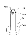
(実施の形態2)
図4は実施の形態2を示し、支持ピンの第1変形例を示す斜視図である。本実施の形態では、支持ピンのみが、実施の形態1と異なるのみなので、異なる部分のみ説明し、他の部分の図と説明を省略する。図4において、支持ピン14の先端14aには、減摩部材としてのテフロン円柱15が嵌め込まれている。この場合、テフロン円柱15は転動せずに固定され、表面15a上をガラス基板3が摺動する。しかし、テフロンは四フッ化エチレンに属し、摩擦係数は極めて小さいので、ガラス基板3に傷が付くようなことはない。また、支持ピン14の下部には、実施の形態1と同様に、台座14bが形成され、支持ピン14を台ガラス2に接着するとき、安定性が保持できるようになっている。すなわち、支持ピン14は実施の形態1の支持ピン4に替えて、台ガラス2上に接着される。その他の構成は実施の形態1と同一である。
【0016】
本実施の形態によれば、実施の形態1と同様の効果に加え、テフロン円柱は単価が安く、支持ピンに着脱可能に嵌合されているので、テフロン円柱15の交換を容易に行うことができ、かつ支持ピン全体の高さのバラツキを少なくすることができる。なお、ガラス基板3との摩擦を小さくしたければ、テフロン円柱15の先端を半球状に形成することも可能であり、交換を要しなければ、テフロン円柱15をカシメて固定することも可能である。
【0017】
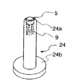
(実施の形態3)
図5は実施の形態3を示し、支持ピンの第2変形例を示す斜視図である。本実施の形態では、支持ピンのみが、実施の形態1と異なるのみなので、異なる部分のみ説明し、他の部分の図と説明を省略する。図5において、支持ピン24の先端のカシメ部24aには、テフロン球5が転動自在かつ飛び出さないように埋設されており、さらに、テフロン球5の下方には圧縮バネ9が装着され、弾発力によりテフロン球5を上方に付勢している。また、支持ピン24の下部には、実施の形態1と同様に、台座24bが形成され、支持ピン24を台ガラス2に接着するとき、安定性が保持できるようになっている。すなわち、支持ピン24は実施の形態1の支持ピン4に替えて、台ガラス2上に接着される。その他の構成は実施の形態1と同一である。
【0018】
本実施の形態によれば、実施の形態1と同様の効果に加え、支持ピンに垂直方向の力が加わると、テフロン球5がカシメ部24aから離れて良好に転動するため、ガラス基板と擦れが小さくなり、ガラス基板に傷が付き難くなる。
【0019】
【発明の効果】
本発明によれば、ガラス基板の平面度を保持し、基板表面を傷つけることがなく、撓みや振動の発生を抑えることができる。
【図面の簡単な説明】
【図1】実施の形態1のガラス基板の保持具の斜視図である。
【図2】実施の形態1のガラス基板の保持具の支持ピン付近の縦断面図である。
【図3】実施の形態1の支持ピンの斜視図である。
【図4】実施の形態2の支持ピンの第1変形例を示す斜視図である。
【図5】実施の形態3の支持ピンの第2変形例を示す斜視図である。
【図6】従来技術の基板ホルダの斜視図である。
【符号の説明】
1 保持枠
1a 透過照明用開口
2 台ガラス
3 ガラス基板
4 支持ピン
6 基準ピン
7 整列ピン
8 吸着部[0001]
BACKGROUND OF THE INVENTION
The present invention relates to a holder for holding a glass substrate when manufacturing and inspecting a liquid crystal glass substrate.
[0002]
[Prior art]
Conventionally, a technique described in Japanese Patent Application Laid-Open No. 9-189441 has been disclosed as a “substrate holder” for a holder for holding a large glass substrate such as a liquid crystal glass substrate. This technique will be described with reference to FIG. The
[0003]
[Problems to be solved by the invention]
However, the above prior art has the following problems. That is, recent glass substrates are becoming larger and larger, and have a thickness of 0.7 to 1.1 mm and a width and length of almost 1 m. In the structure in which the
[0004]
The present invention has been made in view of the above-described conventional problems, and an object of the present invention is to maintain the flatness of the glass substrate, and to prevent the occurrence of bending and vibration without damaging the substrate surface. It is to provide a glass substrate holder.
[0005]
[Means for Solving the Problems]
In order to solve the above-mentioned problems, a glass substrate holder of the present invention includes a holding frame in which a rectangular opening for mounting a peripheral portion of a rectangular glass substrate is formed, and a lower portion of the opening of the holding frame is closed. And a base member made of a transparent member that is fixed to the holding frame and that transmits transmitted illumination light, and a plurality of support pins that are arranged on the upper surface of the base member and support the glass substrate horizontally. .
[0006]
The glass substrate holder of the present invention has a plurality of support pins arranged on a base member made of a transparent member that is fixed to the holding frame so as to close the lower part of the opening of the holding frame and that transmits transmitted illumination light. By supporting the glass substrate, the flatness of the glass substrate can be maintained, and the occurrence of bending and vibration can be suppressed.
[0007]
DETAILED DESCRIPTION OF THE INVENTION
Hereinafter, specific embodiments will be described.
[0008]
(Embodiment 1)
1 to 3
[0009]
In FIG. 1 and FIG. 2, the glass substrate holder is disposed so as to move in the horizontal direction by, for example, a stage (not shown) of the substrate inspection apparatus and to be positioned above the transmission illumination device (not shown). The
[0010]
As shown in FIG. 3, the
[0011]
In FIG. 1, two
[0012]
Next, the operation of the glass substrate holder configured as described above will be described. The
[0013]
According to the present embodiment, the glass substrate is supported by the thick base glass as the rigid transparent member via the plurality of support pins, so that the flatness of the glass substrate can be maintained. Further, since the
[0014]
In the present embodiment, the Teflon sphere is used as the anti-friction member, but instead, a sphere made of engineering plastic such as polyamide resin or polycarbonate resin or a sphere made of metal may be used. Moreover, although the thick base glass is used as a rigid transparent member, you may replace with the transparent member which consists of thin tempered glass. Further, it may be replaced with a transparent member made of a transparent plastic material having a high transmittance of transmitted illumination light and having increased rigidity with ribs or the like. Furthermore, in consideration of the bending of the
[0015]
(Embodiment 2)
FIG. 4 shows the second embodiment and is a perspective view showing a first modification of the support pin. In the present embodiment, only the support pins are different from those in the first embodiment, and therefore only the different portions will be described, and the drawings and descriptions of other portions will be omitted. In FIG. 4, a
[0016]
According to the present embodiment, in addition to the same effects as those of the first embodiment, the unit price of the Teflon cylinder is low, and the
[0017]
(Embodiment 3)
FIG. 5 shows the third embodiment and is a perspective view showing a second modification of the support pin. In the present embodiment, only the support pins are different from those in the first embodiment, and therefore only the different portions will be described, and the drawings and descriptions of other portions will be omitted. In FIG. 5, a
[0018]
According to the present embodiment, in addition to the same effect as in the first embodiment, when a force in the vertical direction is applied to the support pin, the
[0019]
【The invention's effect】
According to the present invention, the flatness of the glass substrate can be maintained, and the occurrence of bending and vibration can be suppressed without damaging the substrate surface.
[Brief description of the drawings]
FIG. 1 is a perspective view of a glass substrate holder according to
FIG. 2 is a longitudinal sectional view of the vicinity of a support pin of the glass substrate holder of the first embodiment.
FIG. 3 is a perspective view of a support pin according to the first embodiment.
4 is a perspective view showing a first modification of the support pin of
5 is a perspective view showing a second modification of the support pin of Embodiment 3. FIG.
FIG. 6 is a perspective view of a prior art substrate holder.
[Explanation of symbols]
DESCRIPTION OF
Claims (3)
前記保持枠の開口部の下部を閉塞するように全周を前記保持枠に固定され、透過照明光を透過する透明部材からなる台部材と、
前記台部材の上面に複数配置され前記ガラス基板を水平に支持する支持ピンと、
を備えたことを特徴とするガラス基板保持具。A holding frame formed with a rectangular opening for mounting the peripheral edge of a rectangular glass substrate;
A base member made of a transparent member that is fixed to the holding frame so that the lower part of the opening of the holding frame is closed , and transmits transmitted illumination light ;
A plurality of support pins arranged on the upper surface of the base member to horizontally support the glass substrate;
A glass substrate holder, comprising:
Priority Applications (1)
| Application Number | Priority Date | Filing Date | Title |
|---|---|---|---|
| JP17157098A JP4175697B2 (en) | 1998-06-18 | 1998-06-18 | Glass substrate holder |
Applications Claiming Priority (1)
| Application Number | Priority Date | Filing Date | Title |
|---|---|---|---|
| JP17157098A JP4175697B2 (en) | 1998-06-18 | 1998-06-18 | Glass substrate holder |
Publications (3)
| Publication Number | Publication Date |
|---|---|
| JP2000007146A JP2000007146A (en) | 2000-01-11 |
| JP2000007146A5 JP2000007146A5 (en) | 2005-10-20 |
| JP4175697B2 true JP4175697B2 (en) | 2008-11-05 |
Family
ID=15925605
Family Applications (1)
| Application Number | Title | Priority Date | Filing Date |
|---|---|---|---|
| JP17157098A Expired - Fee Related JP4175697B2 (en) | 1998-06-18 | 1998-06-18 | Glass substrate holder |
Country Status (1)
| Country | Link |
|---|---|
| JP (1) | JP4175697B2 (en) |
Cited By (1)
| Publication number | Priority date | Publication date | Assignee | Title |
|---|---|---|---|---|
| CN110294270A (en) * | 2019-07-23 | 2019-10-01 | 哈尔滨理工大学 | A kind of machining feeding device for preventing scraps during machining from splashing entrance |
Families Citing this family (24)
| Publication number | Priority date | Publication date | Assignee | Title |
|---|---|---|---|---|
| KR100859933B1 (en) * | 2001-07-02 | 2008-09-23 | 올림푸스 가부시키가이샤 | Board Holding Device |
| US6917755B2 (en) * | 2003-02-27 | 2005-07-12 | Applied Materials, Inc. | Substrate support |
| JP4276867B2 (en) | 2003-03-18 | 2009-06-10 | オリンパス株式会社 | Substrate holder and surface inspection apparatus provided with the same |
| JP2006038825A (en) * | 2004-01-22 | 2006-02-09 | Ntn Corp | Micropattern observation device and micropattern correction device using it |
| TWI393875B (en) * | 2004-09-27 | 2013-04-21 | Olympus Corp | Panel holder of panel testing apparatus and panel testing apparatus |
| KR100741289B1 (en) * | 2005-05-16 | 2007-07-23 | 에버테크노 주식회사 | Polarizing film carrier |
| JP5192719B2 (en) * | 2007-04-12 | 2013-05-08 | 株式会社アルバック | Heating apparatus and substrate processing apparatus |
| KR101058187B1 (en) * | 2008-12-05 | 2011-08-22 | 주식회사 에스에프에이 | Cassette system for substrate storage |
| JP2011141127A (en) * | 2010-01-05 | 2011-07-21 | Avanstrate Taiwan Inc | Visual inspection method and visual inspection device for defect part of glass plate |
| JP5549441B2 (en) * | 2010-01-14 | 2014-07-16 | 東京エレクトロン株式会社 | Holder mechanism, load lock device, processing device, and transport mechanism |
| KR101224578B1 (en) * | 2010-11-10 | 2013-01-22 | 주식회사 디엠케이 | Panel support |
| KR101253730B1 (en) * | 2010-11-10 | 2013-04-12 | 주식회사 디엠케이 | pin type panel supports |
| JP6018755B2 (en) * | 2012-01-10 | 2016-11-02 | ヤマハ発動機株式会社 | X-ray inspection equipment |
| JP5939678B2 (en) * | 2012-05-09 | 2016-06-22 | 大塚電子株式会社 | Optical characteristic measuring apparatus and optical characteristic measuring method |
| CN104122710B (en) * | 2013-04-27 | 2017-08-08 | 北京京东方光电科技有限公司 | A kind of display panel and its manufacture method |
| JP5724014B1 (en) * | 2014-04-22 | 2015-05-27 | 株式会社幸和 | Substrate support apparatus and substrate processing apparatus |
| US10892180B2 (en) * | 2014-06-02 | 2021-01-12 | Applied Materials, Inc. | Lift pin assembly |
| CN104391402A (en) * | 2014-12-17 | 2015-03-04 | 合肥京东方光电科技有限公司 | Display device and manufacturing method thereof |
| KR102517909B1 (en) * | 2015-08-12 | 2023-04-05 | (주)선익시스템 | Lift Module and Substrate Transfer Robot Hand Using Thereof |
| US20190086697A1 (en) * | 2016-05-27 | 2019-03-21 | Sharp Kabushiki Kaisha | Method for manufacturing liquid crystal display device |
| EP3473975A1 (en) * | 2017-10-19 | 2019-04-24 | Renishaw PLC | Fixturing apparatus |
| CN108106996B (en) * | 2017-12-25 | 2024-05-28 | 通彩智能科技集团有限公司 | Glass detects holds platform |
| JP6979900B2 (en) * | 2018-02-13 | 2021-12-15 | 株式会社荏原製作所 | A storage medium that stores a board holding member, a board processing device, a control method for the board processing device, and a program. |
| JP7462507B2 (en) * | 2020-07-31 | 2024-04-05 | 三菱電機株式会社 | Support and assembly equipment |
-
1998
- 1998-06-18 JP JP17157098A patent/JP4175697B2/en not_active Expired - Fee Related
Cited By (1)
| Publication number | Priority date | Publication date | Assignee | Title |
|---|---|---|---|---|
| CN110294270A (en) * | 2019-07-23 | 2019-10-01 | 哈尔滨理工大学 | A kind of machining feeding device for preventing scraps during machining from splashing entrance |
Also Published As
| Publication number | Publication date |
|---|---|
| JP2000007146A (en) | 2000-01-11 |
Similar Documents
| Publication | Publication Date | Title |
|---|---|---|
| JP4175697B2 (en) | Glass substrate holder | |
| CN103376059A (en) | Optical inspection device | |
| JP2000007146A5 (en) | ||
| JP2012221925A (en) | Assembly jig | |
| KR101887655B1 (en) | Horizontal Type PCB Bonding Equipment | |
| KR20190070660A (en) | Lamination apparatus and lamination method using the same for reducing the incidence of oca scratches | |
| JP4312990B2 (en) | LCD table inspection table | |
| CN114768911B (en) | A bottom three-point supported side-pushing slide rack | |
| TW200424528A (en) | Apparatus for inspecting substrate | |
| CN110039753B (en) | Flexible circuit board bending device and bending method thereof | |
| JP2001117077A (en) | Liquid crystal display | |
| CN101344655B (en) | Liquid crystal panel bearing device | |
| KR101038026B1 (en) | Board Support Structure | |
| JP3110608B2 (en) | Display panel inspection equipment | |
| JP4079651B2 (en) | Substrate support device | |
| KR100828950B1 (en) | Panel pusher and flattening probe unit for keeping flat panel display flat | |
| JP2010128210A (en) | Inspection device for liquid crystal display panel | |
| JP4197861B2 (en) | LCD panel inspection jig | |
| CN109865692A (en) | A kind of cleaning assemblies of cleaner for light guide plate | |
| JP2575580Y2 (en) | Circuit board support device | |
| JP2000088701A (en) | Substrate support | |
| CN221443036U (en) | Pressure holding device and automobile display screen pressure holding equipment | |
| KR102217251B1 (en) | Apparatus of bonding a curved substrate | |
| KR102217249B1 (en) | Apparatus of bonding a curved substrate | |
| JPH1194755A (en) | Vibration preventive mechanism for substrate |
Legal Events
| Date | Code | Title | Description |
|---|---|---|---|
| A521 | Written amendment |
Free format text: JAPANESE INTERMEDIATE CODE: A523 Effective date: 20050617 |
|
| A621 | Written request for application examination |
Free format text: JAPANESE INTERMEDIATE CODE: A621 Effective date: 20050617 |
|
| A131 | Notification of reasons for refusal |
Free format text: JAPANESE INTERMEDIATE CODE: A131 Effective date: 20080507 |
|
| A521 | Written amendment |
Free format text: JAPANESE INTERMEDIATE CODE: A523 Effective date: 20080707 |
|
| TRDD | Decision of grant or rejection written | ||
| A01 | Written decision to grant a patent or to grant a registration (utility model) |
Free format text: JAPANESE INTERMEDIATE CODE: A01 Effective date: 20080805 |
|
| A01 | Written decision to grant a patent or to grant a registration (utility model) |
Free format text: JAPANESE INTERMEDIATE CODE: A01 |
|
| A61 | First payment of annual fees (during grant procedure) |
Free format text: JAPANESE INTERMEDIATE CODE: A61 Effective date: 20080819 |
|
| FPAY | Renewal fee payment (event date is renewal date of database) |
Free format text: PAYMENT UNTIL: 20110829 Year of fee payment: 3 |
|
| FPAY | Renewal fee payment (event date is renewal date of database) |
Free format text: PAYMENT UNTIL: 20120829 Year of fee payment: 4 |
|
| FPAY | Renewal fee payment (event date is renewal date of database) |
Free format text: PAYMENT UNTIL: 20130829 Year of fee payment: 5 |
|
| LAPS | Cancellation because of no payment of annual fees |