JP4173904B2 - 平坦な台から成る3次元アンテナアレイを有するセキュリティタグとその製作方法 - Google Patents
平坦な台から成る3次元アンテナアレイを有するセキュリティタグとその製作方法 Download PDFInfo
- Publication number
- JP4173904B2 JP4173904B2 JP2006523925A JP2006523925A JP4173904B2 JP 4173904 B2 JP4173904 B2 JP 4173904B2 JP 2006523925 A JP2006523925 A JP 2006523925A JP 2006523925 A JP2006523925 A JP 2006523925A JP 4173904 B2 JP4173904 B2 JP 4173904B2
- Authority
- JP
- Japan
- Prior art keywords
- dipole
- antenna
- insulating substrate
- frequency
- stub
- Prior art date
- Legal status (The legal status is an assumption and is not a legal conclusion. Google has not performed a legal analysis and makes no representation as to the accuracy of the status listed.)
- Expired - Fee Related
Links
- 238000004519 manufacturing process Methods 0.000 title claims description 10
- NJPPVKZQTLUDBO-UHFFFAOYSA-N novaluron Chemical compound C1=C(Cl)C(OC(F)(F)C(OC(F)(F)F)F)=CC=C1NC(=O)NC(=O)C1=C(F)C=CC=C1F NJPPVKZQTLUDBO-UHFFFAOYSA-N 0.000 title 1
- 239000000758 substrate Substances 0.000 claims description 27
- 238000000034 method Methods 0.000 claims description 14
- 238000005452 bending Methods 0.000 claims description 6
- 238000001514 detection method Methods 0.000 abstract description 3
- 239000000463 material Substances 0.000 description 15
- 238000005520 cutting process Methods 0.000 description 2
- 238000005530 etching Methods 0.000 description 2
- 238000004080 punching Methods 0.000 description 2
- RYGMFSIKBFXOCR-UHFFFAOYSA-N Copper Chemical compound [Cu] RYGMFSIKBFXOCR-UHFFFAOYSA-N 0.000 description 1
- BQCADISMDOOEFD-UHFFFAOYSA-N Silver Chemical compound [Ag] BQCADISMDOOEFD-UHFFFAOYSA-N 0.000 description 1
- 238000004891 communication Methods 0.000 description 1
- 229910052802 copper Inorganic materials 0.000 description 1
- 239000010949 copper Substances 0.000 description 1
- 238000010586 diagram Methods 0.000 description 1
- 230000005672 electromagnetic field Effects 0.000 description 1
- -1 flat table Substances 0.000 description 1
- 239000011888 foil Substances 0.000 description 1
- 238000009434 installation Methods 0.000 description 1
- 238000003698 laser cutting Methods 0.000 description 1
- 239000011159 matrix material Substances 0.000 description 1
- 239000002184 metal Substances 0.000 description 1
- 229910052751 metal Inorganic materials 0.000 description 1
- 238000012986 modification Methods 0.000 description 1
- 230000004048 modification Effects 0.000 description 1
- 239000012811 non-conductive material Substances 0.000 description 1
- 239000005022 packaging material Substances 0.000 description 1
- 238000004806 packaging method and process Methods 0.000 description 1
- 238000007747 plating Methods 0.000 description 1
- 239000002861 polymer material Substances 0.000 description 1
- 230000035945 sensitivity Effects 0.000 description 1
- 229910052709 silver Inorganic materials 0.000 description 1
- 239000004332 silver Substances 0.000 description 1
Images


Classifications
-
- H—ELECTRICITY
- H01—ELECTRIC ELEMENTS
- H01Q—ANTENNAS, i.e. RADIO AERIALS
- H01Q1/00—Details of, or arrangements associated with, antennas
- H01Q1/12—Supports; Mounting means
- H01Q1/22—Supports; Mounting means by structural association with other equipment or articles
- H01Q1/2208—Supports; Mounting means by structural association with other equipment or articles associated with components used in interrogation type services, i.e. in systems for information exchange between an interrogator/reader and a tag/transponder, e.g. in Radio Frequency Identification [RFID] systems
- H01Q1/2225—Supports; Mounting means by structural association with other equipment or articles associated with components used in interrogation type services, i.e. in systems for information exchange between an interrogator/reader and a tag/transponder, e.g. in Radio Frequency Identification [RFID] systems used in active tags, i.e. provided with its own power source or in passive tags, i.e. deriving power from RF signal
-
- G—PHYSICS
- G06—COMPUTING; CALCULATING OR COUNTING
- G06K—GRAPHICAL DATA READING; PRESENTATION OF DATA; RECORD CARRIERS; HANDLING RECORD CARRIERS
- G06K19/00—Record carriers for use with machines and with at least a part designed to carry digital markings
- G06K19/06—Record carriers for use with machines and with at least a part designed to carry digital markings characterised by the kind of the digital marking, e.g. shape, nature, code
- G06K19/067—Record carriers with conductive marks, printed circuits or semiconductor circuit elements, e.g. credit or identity cards also with resonating or responding marks without active components
- G06K19/07—Record carriers with conductive marks, printed circuits or semiconductor circuit elements, e.g. credit or identity cards also with resonating or responding marks without active components with integrated circuit chips
- G06K19/077—Constructional details, e.g. mounting of circuits in the carrier
- G06K19/07749—Constructional details, e.g. mounting of circuits in the carrier the record carrier being capable of non-contact communication, e.g. constructional details of the antenna of a non-contact smart card
- G06K19/07773—Antenna details
- G06K19/07786—Antenna details the antenna being of the HF type, such as a dipole
-
- H—ELECTRICITY
- H01—ELECTRIC ELEMENTS
- H01Q—ANTENNAS, i.e. RADIO AERIALS
- H01Q1/00—Details of, or arrangements associated with, antennas
- H01Q1/12—Supports; Mounting means
- H01Q1/22—Supports; Mounting means by structural association with other equipment or articles
- H01Q1/24—Supports; Mounting means by structural association with other equipment or articles with receiving set
-
- H—ELECTRICITY
- H01—ELECTRIC ELEMENTS
- H01Q—ANTENNAS, i.e. RADIO AERIALS
- H01Q21/00—Antenna arrays or systems
- H01Q21/24—Combinations of antenna units polarised in different directions for transmitting or receiving circularly and elliptically polarised waves or waves linearly polarised in any direction
- H01Q21/26—Turnstile or like antennas comprising arrangements of three or more elongated elements disposed radially and symmetrically in a horizontal plane about a common centre
-
- H—ELECTRICITY
- H01—ELECTRIC ELEMENTS
- H01Q—ANTENNAS, i.e. RADIO AERIALS
- H01Q9/00—Electrically-short antennas having dimensions not more than twice the operating wavelength and consisting of conductive active radiating elements
- H01Q9/04—Resonant antennas
- H01Q9/16—Resonant antennas with feed intermediate between the extremities of the antenna, e.g. centre-fed dipole
- H01Q9/28—Conical, cylindrical, cage, strip, gauze, or like elements having an extended radiating surface; Elements comprising two conical surfaces having collinear axes and adjacent apices and fed by two-conductor transmission lines
- H01Q9/285—Planar dipole
Landscapes
- Engineering & Computer Science (AREA)
- Theoretical Computer Science (AREA)
- Computer Hardware Design (AREA)
- Microelectronics & Electronic Packaging (AREA)
- Physics & Mathematics (AREA)
- General Physics & Mathematics (AREA)
- Computer Networks & Wireless Communication (AREA)
- Details Of Aerials (AREA)
- Variable-Direction Aerials And Aerial Arrays (AREA)
- Radar Systems Or Details Thereof (AREA)
- Aerials With Secondary Devices (AREA)
- Burglar Alarm Systems (AREA)
- Support Of Aerials (AREA)
Description
しかしながら、特に、RFIDタグとの交信にUHF周波数(例えば、850−950MHz)やマイクロ波周波数(例えば、2.3−2.6GHz)を使用する場合、RFIDタグが配置される所定体積に対して検出を最適化するUHF(又はマイクロ波)ダイポールアンテナシステムへの必要が残る。
20 RFIDセキュリティタグ
22 RFID集積回路
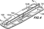
24 ウェブ材料
122 外方要素
124 内方要素
126 背面シェル
Claims (15)
- インタロゲータ又はリーダから発信された信号の受信を最適化するセキュリティタグに使用されるアンテナ構造において、
平坦な絶縁基板(24)の上に非平行で非コリニアな構造に配置された第1ダイポール(X1、X2)及び第2ダイポール(Y1、Y2)と、部分(FE)を有する第3ダイポール(Z1、Z2)とを備え、更に、第3ダイポール(Z1、Z2)は、絶縁基板(24)の上に形成された後、上記部分(FE)を絶縁基板(24)から切離して上記部分(FE)を絶縁基板(24)から折り曲げることにより、絶縁基板(24)から突出するアンテナ構造。 - 第3ダイポール(Z1、Z2)が、第1アンテナスタブ(Z1)と第2アンテナスタブ(Z2)を備え、更に、絶縁基板(24)が、互いに反対の第1面と第2面を含み、更に、第1アンテナスタブ(Z1)が、第1面側で絶縁基板(24)の外に配置される一方、第2アンテナスタブ(Z2)が、第2面側で絶縁基板(24)の外に配置される請求項1に記載のアンテナ構造。
- 第1アンテナスタブ(Z1)と第2アンテナスタブ(Z2)が、夫々、第1面と第2面に対して直角に配置される請求項2に記載のアンテナ構造。
- 第1ダイポール(X1、X2)、第2ダイポール(Y1、Y2)と第3ダイポール(Z1、Z2)が、RF周波数に同調される請求項2に記載のアンテナ構造。
- 上記RF周波数が、約850−950MHzの周波数帯のUHF周波数である請求項4に記載のアンテナ構造。
- 上記RF周波数が、約2.3−2.6GHzの周波数帯のマイクロ波周波数である請求項4に記載のアンテナ構造。
- 第1ダイポール(X1、X2)、第2ダイポール(Y1、Y2)と第3ダイポール(Z1、Z2)が、RF周波数に同調される請求項3に記載のアンテナ構造。
- 上記RF周波数が、約850−950MHzの周波数帯のUHF周波数である請求項7に記載のアンテナ構造。
- 上記RF周波数が、約2.3−2.6GHzの周波数帯のマイクロ波周波数である請求項7に記載のアンテナ構造。
- インタロゲータ又はリーダから発信された信号の受信を最適化するセキュリティタグ用の3次元アンテナを製作する方法において、
平坦な絶縁基板(24)を供給するステップ(a)と、第1ダイポール(X1、X2)と第2ダイポール(Y1、Y2)を、互いに非平行で非コリニアに絶縁基板(24)上に形成するステップ(b)と、第3ダイポール(Z1、Z2)を絶縁基板(24)上に形成するステップ(c)と、第3ダイポール(Z1、Z2)の部分(FE)を絶縁基板(24)から切離すステップ(d)と、第3ダイポール(Z1、Z2)の上記部分(FE)を絶縁基板(24)から折り曲げるステップ(e)とを備える方法。 - 上記ステップ(c)が、第1アンテナスタブ(Z1)と第2アンテナスタブ(Z2)を作製するステップを備え、更に、上記ステップ(d)が、第1アンテナスタブ(Z1)の第1部分(FE)を絶縁基板(24)から切離すと共に第2アンテナスタブ(Z2)の第2部分(FE)を絶縁基板(24)から切離すステップを備える請求項10に記載の方法。
- 絶縁基板(24)が、互いに反対の第1面と第2面を含み、更に、上記ステップ(e)が、第1部分(FE)と第2部分(FE)を第1面から又は第2面から折り曲げるステップを備える請求項11に記載の方法。
- 絶縁基板(24)が、互いに反対の第1面と第2面を含み、更に、上記ステップ(e)が、第1部分(FE)を第1面から折り曲げると共に、第2部分(FE)を第2面から折り曲げるステップを備える請求項11に記載の方法。
- 第1部分(FE)と第2部分(FE)を第1面から又は第2面から折り曲げる上記ステップが、第1部分(FE)と第2部分(FE)を第1面から又は第2面から直角に折り曲げるステップを備える請求項12に記載の方法。
- 第1部分(FE)を第1面から折り曲げると共に、第2部分(FE)を第2面から折り曲げる上記ステップが、第1部分(FE)と第2部分(FE)を、夫々、第1面と第2面から直角に折り曲げるステップを備える請求項13に記載の方法。
Applications Claiming Priority (3)
| Application Number | Priority Date | Filing Date | Title |
|---|---|---|---|
| US49709903P | 2003-08-22 | 2003-08-22 | |
| US10/914,432 US7042413B2 (en) | 2003-08-22 | 2004-08-09 | Security tag with three dimensional antenna array made from flat stock |
| PCT/US2004/026053 WO2005022690A1 (en) | 2003-08-22 | 2004-08-11 | Security tag with three dimensional antenna array made from flat stock and fabrication method thereof |
Publications (2)
| Publication Number | Publication Date |
|---|---|
| JP2007534196A JP2007534196A (ja) | 2007-11-22 |
| JP4173904B2 true JP4173904B2 (ja) | 2008-10-29 |
Family
ID=34198233
Family Applications (1)
| Application Number | Title | Priority Date | Filing Date |
|---|---|---|---|
| JP2006523925A Expired - Fee Related JP4173904B2 (ja) | 2003-08-22 | 2004-08-11 | 平坦な台から成る3次元アンテナアレイを有するセキュリティタグとその製作方法 |
Country Status (12)
| Country | Link |
|---|---|
| US (1) | US7042413B2 (ja) |
| EP (1) | EP1656714B1 (ja) |
| JP (1) | JP4173904B2 (ja) |
| KR (1) | KR20060103425A (ja) |
| CN (1) | CN1839516B (ja) |
| AT (1) | ATE415000T1 (ja) |
| AU (1) | AU2004302771B2 (ja) |
| CA (1) | CA2536386C (ja) |
| DE (1) | DE602004017877D1 (ja) |
| ES (1) | ES2317048T3 (ja) |
| TW (1) | TWI244236B (ja) |
| WO (1) | WO2005022690A1 (ja) |
Families Citing this family (85)
| Publication number | Priority date | Publication date | Assignee | Title |
|---|---|---|---|---|
| US6606485B1 (en) * | 1999-10-06 | 2003-08-12 | Qualcomm, Incorporated | Candidate system search and soft handoff between frequencies in a multi-carrier mobile communication system |
| US20040250417A1 (en) * | 2003-06-12 | 2004-12-16 | Arneson Michael R. | Method, system, and apparatus for transfer of dies using a die plate |
| JP2005216077A (ja) * | 2004-01-30 | 2005-08-11 | Bridgestone Corp | Rfid組込バーコードラベル、及び、タイヤとその管理方法 |
| JP2006024087A (ja) * | 2004-07-09 | 2006-01-26 | Nec Corp | 無線デバイス、その製造方法、その検査方法及び検査装置並びに無線装置及びその製造方法 |
| US7432874B2 (en) * | 2004-07-22 | 2008-10-07 | Feig Electronic Gmbh | Antenna array |
| KR20070055523A (ko) * | 2004-08-31 | 2007-05-30 | 가부시끼가이샤 우찌다 요오꼬오 | 프레젠테이션 시스템 |
| JP4290620B2 (ja) * | 2004-08-31 | 2009-07-08 | 富士通株式会社 | Rfidタグ、rfidタグ用アンテナ、rfidタグ用アンテナシートおよびrfidタグの製造方法 |
| JP4465600B2 (ja) * | 2004-09-15 | 2010-05-19 | オムロン株式会社 | 認識札、取り付け方法、および認識札付容器 |
| US7615479B1 (en) * | 2004-11-08 | 2009-11-10 | Alien Technology Corporation | Assembly comprising functional block deposited therein |
| KR101038493B1 (ko) * | 2004-11-12 | 2011-06-01 | 삼성테크윈 주식회사 | 극초단파용 라디오 주파수 인식태그 제조방법 |
| WO2006071904A2 (en) * | 2004-12-27 | 2006-07-06 | Radianse, Inc. | Antennas for object identifiers in location systems |
| DE102005018803A1 (de) * | 2005-04-22 | 2006-10-26 | Mühlbauer Ag | Transponder mit einer Dipol-Antenne |
| US7262701B1 (en) * | 2005-05-23 | 2007-08-28 | National Semiconductor Corporation | Antenna structures for RFID devices |
| EP1770874A1 (en) * | 2005-09-28 | 2007-04-04 | Nortel Networks Limited | Antenna system for a radiocommunication station, and radiocommunication station having such antenna system |
| US20070152831A1 (en) * | 2006-01-05 | 2007-07-05 | Sean Eisele | 3-axis RFID tag antenna |
| US20080068132A1 (en) * | 2006-05-16 | 2008-03-20 | Georges Kayanakis | Contactless radiofrequency device featuring several antennas and related antenna selection circuit |
| FR2901435B1 (fr) * | 2006-05-16 | 2008-08-08 | Ask Sa | Dispositif sans contact radiofrequence comportant plusieurs antennes et circuit de selection d'antennes associe |
| US7659857B2 (en) * | 2006-07-05 | 2010-02-09 | King Patrick F | System and method for providing a low and narrow-profile radio frequency identification (RFID) tag |
| US20080074271A1 (en) * | 2006-09-27 | 2008-03-27 | Science Applications International Corporation | Radio frequency transponders having three-dimensional antennas |
| US8781522B2 (en) | 2006-11-02 | 2014-07-15 | Qualcomm Incorporated | Adaptable antenna system |
| US7545338B2 (en) * | 2006-11-16 | 2009-06-09 | Tdk Corporation | Log-periodic dipole array (LPDA) antenna and method of making |
| DE102006059745A1 (de) | 2006-12-18 | 2008-06-19 | Grammer Ag | Luftfeder für einen Fahrzeugsitz sowie Fahrzeugsitz mit einer derartigen Luftfeder |
| US7798090B2 (en) * | 2007-01-05 | 2010-09-21 | Thomas Angell Hatfield | Rescue and locational determination equipment |
| WO2008099309A1 (en) * | 2007-02-13 | 2008-08-21 | Nxp B.V. | Transponder |
| US7859408B2 (en) | 2007-03-28 | 2010-12-28 | Round Rock Research, Llc | Methods and systems of determining physical characteristics associated with objects tagged with RFID tags |
| US7880618B2 (en) * | 2007-03-28 | 2011-02-01 | Round Rock Research, Llc | Methods and systems of determining physical characteristics associated with objects tagged with RFID tags |
| US7868841B2 (en) * | 2007-04-11 | 2011-01-11 | Vubiq Incorporated | Full-wave di-patch antenna |
| US20080252483A1 (en) * | 2007-04-11 | 2008-10-16 | Science Applications International Corporation | Radio frequency transponders embedded in surfaces |
| DE102007019365B4 (de) | 2007-04-23 | 2013-04-11 | Grammer Aktiengesellschaft | Verfahren und Vorrichtung zur Auswertung von auf eine Person wirkenden Schwingungen eines Fahrzeuges |
| DE102007019366B4 (de) | 2007-04-23 | 2016-12-15 | Grammer Ag | Vorrichtung und Verfahren zur Erfassung von auf eine Person übertragene Schwingungen eines Fahrzeuges |
| JP4806373B2 (ja) * | 2007-05-09 | 2011-11-02 | 富士通株式会社 | タグ装置及びそれを用いたrfidシステム |
| US20080280560A1 (en) * | 2007-05-09 | 2008-11-13 | Micron Technology, Inc. | Method and system of placing a rfid tag in a continuous transmission mode |
| ITTO20070420A1 (it) * | 2007-06-13 | 2008-12-14 | Telsey S P A | Gateway provvisto di un sistema di ricetrasmissione multi-antenna con architettura miso per comunicazioni wi-fi |
| DE102007032897B4 (de) | 2007-07-14 | 2014-05-28 | Grammer Aktiengesellschaft | Fahrzeugsitz mit einem Grundrahmen und einem gegenüber diesem Grundrahmen realtivbeweglichen Sitzrahmen |
| US8289163B2 (en) | 2007-09-27 | 2012-10-16 | 3M Innovative Properties Company | Signal line structure for a radio-frequency identification system |
| US7932814B2 (en) * | 2007-10-04 | 2011-04-26 | Round Rock Research, Llc | Method and system to determine physical parameters as between a RFID tag and a reader |
| US7944356B2 (en) * | 2007-10-04 | 2011-05-17 | Round Rock Research, Llc | Method and system to determine physical parameters as between an RFID tag and a reader |
| US8717244B2 (en) | 2007-10-11 | 2014-05-06 | 3M Innovative Properties Company | RFID tag with a modified dipole antenna |
| DE102007056700B4 (de) | 2007-11-24 | 2012-03-29 | Grammer Aktiengesellschaft | Vorrichtung mit einem Federungssystem sowie Verfahren zur Einstellung eines Federungssystems |
| US7982616B2 (en) | 2008-02-14 | 2011-07-19 | 3M Innovative Properties Company | Radio frequency identification (RFID) tag including a three-dimensional loop antenna |
| GB0802729D0 (en) * | 2008-02-14 | 2008-03-26 | Isis Innovation | Resonant reflector assembly and method |
| DE102008022045B3 (de) | 2008-05-03 | 2009-07-30 | Grammer Ag | Fahrzeugsitz mit einer Einrichtung zur Steuerung eines pneumatisch geregelten Federungssystems |
| US8830062B2 (en) | 2008-06-05 | 2014-09-09 | Micron Technology, Inc. | Systems and methods to use radar in RFID systems |
| US8461966B2 (en) | 2008-06-05 | 2013-06-11 | Micron Technology, Inc. | Systems and methods to determine kinematical parameters using RFID tags |
| US8242888B2 (en) * | 2008-06-05 | 2012-08-14 | Keystone Technology Solutions, Llc | Systems and methods to determine motion parameters using RFID tags |
| US8319610B2 (en) * | 2008-08-12 | 2012-11-27 | Industrial Technology Research Institute | Radio-frequency identification (RFID) antenna, tags and communications systems using the same |
| US8174385B2 (en) * | 2008-09-29 | 2012-05-08 | Mitac Technology Corp. | Radio frequency identification reader having antennas in different directions |
| DE102008052960B4 (de) | 2008-10-23 | 2014-02-13 | Grammer Aktiengesellschaft | Federungsschwingungssystem zur Schwingungsreduzierung |
| DE102008056200B4 (de) | 2008-11-06 | 2014-04-03 | Grammer Aktiengesellschaft | Scherengestell für einen Fahrzeugsitz, Fahrzeugsitz, insbesondere Kraftfahrzeugsitz, und Verfahren zum Herstellen eines Unterbaus eines Fahrzeugsitzes |
| DE102008054609A1 (de) | 2008-12-14 | 2010-06-24 | Getac Technology Corp. | Funkfrequenzidentifikations-Leser mit Antennen in verschiedenen Richtungen |
| US8466837B2 (en) * | 2008-12-31 | 2013-06-18 | Navcom Technology Inc. | Hooked turnstile antenna for navigation and communication |
| US8068012B2 (en) * | 2009-01-08 | 2011-11-29 | Intelleflex Corporation | RFID device and system for setting a level on an electronic device |
| DE102009005381B4 (de) | 2009-01-21 | 2013-05-08 | Grammer Aktiengesellschaft | Vorrichtung zum Federn einer Masse und Verfahren zum Einstellen und/oder Betreiben einer Fluidfeder |
| US20100231461A1 (en) * | 2009-03-13 | 2010-09-16 | Qualcomm Incorporated | Frequency selective multi-band antenna for wireless communication devices |
| US8054237B2 (en) * | 2009-05-28 | 2011-11-08 | Winegard Company | Compact high definition digital television antenna |
| CN101908158A (zh) * | 2010-02-10 | 2010-12-08 | 邹谊 | 一种支持三维方向识别的电子标签 |
| US9122967B2 (en) | 2010-04-14 | 2015-09-01 | Technologies Roi, Llc | Radio frequency identification tags and methods employing ceramic components, which may be suitable for use in extreme environmental conditions |
| CN102263324B (zh) * | 2011-07-28 | 2016-05-18 | 群淂数码科技(上海)有限公司 | 射频识别标签天线 |
| USD665385S1 (en) * | 2011-10-28 | 2012-08-14 | Winegard Company | Digital television antenna |
| TWI502812B (zh) * | 2012-07-24 | 2015-10-01 | Univ Nat Kaohsiung Marine | Dual polarized antenna |
| US9324020B2 (en) * | 2012-08-30 | 2016-04-26 | Nxp B.V. | Antenna structures and methods for omni directional radiation patterns |
| CN104347936B (zh) * | 2013-07-24 | 2017-10-10 | 深圳光启创新技术有限公司 | 立体天线的制备方法、立体天线及天线系统 |
| US10027030B2 (en) | 2013-12-11 | 2018-07-17 | Nuvotronics, Inc | Dielectric-free metal-only dipole-coupled broadband radiating array aperture with wide field of view |
| JP2017505075A (ja) * | 2014-01-31 | 2017-02-09 | クインテル テクノロジー リミテッド | ビーム幅制御を伴うアンテナシステム |
| JP6327886B2 (ja) * | 2014-02-28 | 2018-05-23 | 三菱重工機械システム株式会社 | 無線タグ、通信端末、及び通信システム |
| JP2017510243A (ja) * | 2014-03-27 | 2017-04-06 | ヒューマヴォックス リミテッド | 新規のプローブ配置 |
| USD766884S1 (en) * | 2014-05-19 | 2016-09-20 | Airgain Incorporated | Antenna |
| USD754641S1 (en) * | 2014-05-29 | 2016-04-26 | Winegard Company | Flat antenna for digital television reception |
| US9390367B2 (en) * | 2014-07-08 | 2016-07-12 | Wernher von Braun Centro de Pesquisas Avancadas | RFID tag and RFID tag antenna |
| WO2016063758A1 (ja) | 2014-10-20 | 2016-04-28 | 株式会社村田製作所 | アンテナモジュール |
| CN105576351B (zh) * | 2014-11-05 | 2018-05-22 | 中国移动通信集团设计院有限公司 | 一种天线辐射单元及天线 |
| US9520052B2 (en) * | 2015-04-15 | 2016-12-13 | Innovative Control Systems, Inc. | Security tag system with improved range consistency |
| USD784965S1 (en) * | 2015-07-10 | 2017-04-25 | Airgain Incorporated | Antenna |
| US10431896B2 (en) | 2015-12-16 | 2019-10-01 | Cubic Corporation | Multiband antenna with phase-center co-allocated feed |
| DE102016010916A1 (de) * | 2016-09-08 | 2018-03-08 | Giesecke+Devrient Mobile Security Gmbh | Sicherheitssiegel |
| WO2018045550A1 (en) * | 2016-09-09 | 2018-03-15 | Hong Kong R&D Centre for Logistics and Supply Chain Management Enabling Technologies Limited | A radio frequency communication device and a method for using thereof |
| USD879077S1 (en) * | 2017-01-13 | 2020-03-24 | Impinj, Inc. | Crossover for RFID IC terminals |
| US11196184B2 (en) | 2017-06-20 | 2021-12-07 | Cubic Corporation | Broadband antenna array |
| WO2019209461A1 (en) | 2018-04-25 | 2019-10-31 | Nuvotronics, Inc. | Microwave/millimeter-wave waveguide to circuit board connector |
| FR3085550B1 (fr) * | 2018-08-31 | 2021-05-14 | Commissariat Energie Atomique | Dispositif antennaire compact |
| CN113168549A (zh) * | 2018-11-16 | 2021-07-23 | 艾利丹尼森零售信息服务有限公司 | 用于形成和放置射频识别标签的方法、系统和装置 |
| US11367948B2 (en) | 2019-09-09 | 2022-06-21 | Cubic Corporation | Multi-element antenna conformed to a conical surface |
| USD918878S1 (en) * | 2019-11-18 | 2021-05-11 | David Liu | Color LED film antenna |
| US11784418B2 (en) * | 2021-10-12 | 2023-10-10 | Qualcomm Incorporated | Multi-directional dual-polarized antenna system |
| DE102021213951A1 (de) * | 2021-12-08 | 2023-06-15 | Contitech Techno-Chemie Gmbh | Identifikationselement, vorzugsweise für Medienführungen |
Family Cites Families (43)
| Publication number | Priority date | Publication date | Assignee | Title |
|---|---|---|---|---|
| US3478363A (en) * | 1968-03-07 | 1969-11-11 | Laurence C Wells | Horizontal v-shaped dipole antenna for television reception |
| US4446465A (en) | 1978-11-02 | 1984-05-01 | Harris Corporation | Low windload circularly polarized antenna |
| US4782345A (en) | 1986-07-29 | 1988-11-01 | Amtech Corporation | Transponder antenna |
| US4816839A (en) | 1987-12-18 | 1989-03-28 | Amtech Corporation | Transponder antenna |
| US4853705A (en) | 1988-05-11 | 1989-08-01 | Amtech Technology Corporation | Beam powered antenna |
| US5056111A (en) | 1988-08-09 | 1991-10-08 | Ibm Corporation | Integrated terahertz electromagnetic wave system |
| US5173715A (en) * | 1989-12-04 | 1992-12-22 | Trimble Navigation | Antenna with curved dipole elements |
| US5187449A (en) | 1989-12-15 | 1993-02-16 | Ibm Corporation | Coplanar transmission line millimeter radiation source |
| US5610595A (en) | 1991-12-09 | 1997-03-11 | Intermec Corporation | Packet radio communication system protocol |
| US5572226A (en) * | 1992-05-15 | 1996-11-05 | Micron Technology, Inc. | Spherical antenna pattern(s) from antenna(s) arranged in a two-dimensional plane for use in RFID tags and labels |
| DE4319878A1 (de) * | 1992-06-17 | 1993-12-23 | Micron Technology Inc | Hochfrequenz-Identifikationseinrichtung (HFID) und Verfahren zu ihrer Herstellung |
| JP3324243B2 (ja) | 1993-03-30 | 2002-09-17 | 三菱電機株式会社 | アンテナ装置およびアンテナシステム |
| DE69412956T2 (de) | 1993-10-04 | 1999-05-12 | Amtech Corp | Mikrostreifenleiterantenne mit modulierter Rückstreustrahlung |
| US5771021A (en) | 1993-10-04 | 1998-06-23 | Amtech Corporation | Transponder employing modulated backscatter microstrip double patch antenna |
| US5440315A (en) | 1994-01-24 | 1995-08-08 | Intermec Corporation | Antenna apparatus for capacitively coupling an antenna ground plane to a moveable antenna |
| US5682143A (en) | 1994-09-09 | 1997-10-28 | International Business Machines Corporation | Radio frequency identification tag |
| US5623271A (en) | 1994-11-04 | 1997-04-22 | Ibm Corporation | Low frequency planar antenna with large real input impedance |
| US5812065A (en) | 1995-08-14 | 1998-09-22 | International Business Machines Corporation | Modulation of the resonant frequency of a circuit using an energy field |
| US5821859A (en) | 1996-06-07 | 1998-10-13 | Ibm Corporation | Concealed magnetic ID code and antitheft tag |
| US6028564A (en) | 1997-01-29 | 2000-02-22 | Intermec Ip Corp. | Wire antenna with optimized impedance for connecting to a circuit |
| US6097347A (en) | 1997-01-29 | 2000-08-01 | Intermec Ip Corp. | Wire antenna with stubs to optimize impedance for connecting to a circuit |
| US7035818B1 (en) | 1997-11-21 | 2006-04-25 | Symbol Technologies, Inc. | System and method for electronic inventory |
| US6215402B1 (en) | 1998-03-13 | 2001-04-10 | Intermec Ip Corp. | Radio frequency identification transponder employing patch antenna |
| US6249227B1 (en) | 1998-01-05 | 2001-06-19 | Intermec Ip Corp. | RFID integrated in electronic assets |
| US6441740B1 (en) | 1998-02-27 | 2002-08-27 | Intermec Ip Corp. | Radio frequency identification transponder having a reflector |
| US6320509B1 (en) | 1998-03-16 | 2001-11-20 | Intermec Ip Corp. | Radio frequency identification transponder having a high gain antenna configuration |
| US6906615B2 (en) | 1998-09-17 | 2005-06-14 | Intermec Ip Corp | Reference circuit enhancement for passive RFID tags |
| US6278413B1 (en) | 1999-03-29 | 2001-08-21 | Intermec Ip Corporation | Antenna structure for wireless communications device, such as RFID tag |
| US6229408B1 (en) | 1999-05-19 | 2001-05-08 | Intermec Ip Corp. | Zero loss bias “T” |
| US6249260B1 (en) * | 1999-07-16 | 2001-06-19 | Comant Industries, Inc. | T-top antenna for omni-directional horizontally-polarized operation |
| US6140146A (en) | 1999-08-03 | 2000-10-31 | Intermec Ip Corp. | Automated RFID transponder manufacturing on flexible tape substrates |
| US6317098B1 (en) | 1999-08-23 | 2001-11-13 | Lucent Technologies Inc. | Communication employing triply-polarized transmissions |
| US6535175B2 (en) | 2000-06-01 | 2003-03-18 | Intermec Ip Corp. | Adjustable length antenna system for RF transponders |
| JP2002151939A (ja) | 2000-10-03 | 2002-05-24 | Internatl Business Mach Corp <Ibm> | アンテナ装置、情報処理装置および携帯電話 |
| US6563474B2 (en) | 2000-12-21 | 2003-05-13 | Lear Corporation | Remote access device having multiple inductive coil antenna |
| EP2287777A1 (en) | 2001-02-12 | 2011-02-23 | Symbol Technologies, Inc. | Radio frequency identification architecture |
| US6864852B2 (en) * | 2001-04-30 | 2005-03-08 | Ipr Licensing, Inc. | High gain antenna for wireless applications |
| US6812841B2 (en) | 2002-01-23 | 2004-11-02 | Intermec Ip Corp. | Passive RFID tag that retains state after temporary loss of power |
| US7009496B2 (en) | 2002-04-01 | 2006-03-07 | Symbol Technologies, Inc. | Method and system for optimizing an interrogation of a tag population |
| US6859190B2 (en) | 2002-06-04 | 2005-02-22 | Intermec Ip Corp | RFID tag with a quadrupler or N-tupler circuit for efficient RF to DC conversion |
| US7023347B2 (en) | 2002-08-02 | 2006-04-04 | Symbol Technologies, Inc. | Method and system for forming a die frame and for transferring dies therewith |
| US7117581B2 (en) | 2002-08-02 | 2006-10-10 | Symbol Technologies, Inc. | Method for high volume assembly of radio frequency identification tags |
| US6958735B2 (en) * | 2003-07-08 | 2005-10-25 | Handelsman Dan G | Compact and efficient three dimensional antennas |
-
2004
- 2004-08-09 US US10/914,432 patent/US7042413B2/en not_active Expired - Fee Related
- 2004-08-11 DE DE602004017877T patent/DE602004017877D1/de active Active
- 2004-08-11 JP JP2006523925A patent/JP4173904B2/ja not_active Expired - Fee Related
- 2004-08-11 KR KR1020067003555A patent/KR20060103425A/ko active IP Right Grant
- 2004-08-11 CA CA2536386A patent/CA2536386C/en not_active Expired - Fee Related
- 2004-08-11 EP EP04780828A patent/EP1656714B1/en not_active Not-in-force
- 2004-08-11 AU AU2004302771A patent/AU2004302771B2/en not_active Ceased
- 2004-08-11 AT AT04780828T patent/ATE415000T1/de not_active IP Right Cessation
- 2004-08-11 CN CN2004800242005A patent/CN1839516B/zh not_active Expired - Fee Related
- 2004-08-11 WO PCT/US2004/026053 patent/WO2005022690A1/en active Application Filing
- 2004-08-11 ES ES04780828T patent/ES2317048T3/es active Active
- 2004-08-18 TW TW093124798A patent/TWI244236B/zh not_active IP Right Cessation
Also Published As
| Publication number | Publication date |
|---|---|
| DE602004017877D1 (de) | 2009-01-02 |
| AU2004302771B2 (en) | 2008-08-07 |
| KR20060103425A (ko) | 2006-09-29 |
| US20050040994A1 (en) | 2005-02-24 |
| TWI244236B (en) | 2005-11-21 |
| EP1656714A1 (en) | 2006-05-17 |
| CA2536386A1 (en) | 2005-03-10 |
| ES2317048T3 (es) | 2009-04-16 |
| CN1839516A (zh) | 2006-09-27 |
| WO2005022690A1 (en) | 2005-03-10 |
| ATE415000T1 (de) | 2008-12-15 |
| CN1839516B (zh) | 2012-07-04 |
| US7042413B2 (en) | 2006-05-09 |
| CA2536386C (en) | 2010-10-19 |
| EP1656714B1 (en) | 2008-11-19 |
| WO2005022690A8 (en) | 2006-06-22 |
| JP2007534196A (ja) | 2007-11-22 |
| TW200511645A (en) | 2005-03-16 |
| AU2004302771A1 (en) | 2005-03-10 |
Similar Documents
| Publication | Publication Date | Title |
|---|---|---|
| JP4173904B2 (ja) | 平坦な台から成る3次元アンテナアレイを有するセキュリティタグとその製作方法 | |
| US8672230B2 (en) | RFID tag | |
| EP1687762B1 (en) | Rfid tag with enhanced readability | |
| US8544759B2 (en) | Wireless IC device, wireless IC module and method of manufacturing wireless IC module | |
| US8360328B2 (en) | RFID tag | |
| US8960561B2 (en) | Wireless communication device | |
| EP2180432B1 (en) | Radio tag and process for producing the same | |
| US20090160653A1 (en) | Anti-metal RFID tag and manufacturing method thereof | |
| JP2007324865A (ja) | アンテナ回路及びトランスポンダ | |
| EP2458530B1 (en) | Transponder tagged object and method for its manufacturing | |
| JP5176465B2 (ja) | 非接触icタグと非接触icタグのエンコード方法 | |
| EP2225707B1 (en) | Method of manufacturing an antenna or a strap on a substrate for accommodating an integrated circuit | |
| KR20060104789A (ko) | 박막형 rfid 태그 | |
| JP6998086B2 (ja) | Rfタグアンテナ、rfタグおよび導電体付きrfタグ | |
| MXPA06002109A (en) | Security tag with three dimensional antenna array made from flat stock and fabrication method thereof | |
| WO2021124065A1 (en) | Rfid tag arrangement with omnidirectional antenna characteristics | |
| TW202312565A (zh) | 無線射頻晶片模組及其rfid接收器 | |
| KR20050078157A (ko) | Rfid 태그 및 이의 제조 방법 |
Legal Events
| Date | Code | Title | Description |
|---|---|---|---|
| A601 | Written request for extension of time |
Free format text: JAPANESE INTERMEDIATE CODE: A601 Effective date: 20071030 |
|
| RD03 | Notification of appointment of power of attorney |
Free format text: JAPANESE INTERMEDIATE CODE: A7423 Effective date: 20071030 |
|
| A521 | Request for written amendment filed |
Free format text: JAPANESE INTERMEDIATE CODE: A523 Effective date: 20071107 |
|
| A602 | Written permission of extension of time |
Free format text: JAPANESE INTERMEDIATE CODE: A602 Effective date: 20071115 |
|
| A02 | Decision of refusal |
Free format text: JAPANESE INTERMEDIATE CODE: A02 Effective date: 20080226 |
|
| A521 | Request for written amendment filed |
Free format text: JAPANESE INTERMEDIATE CODE: A523 Effective date: 20080613 |
|
| A911 | Transfer to examiner for re-examination before appeal (zenchi) |
Free format text: JAPANESE INTERMEDIATE CODE: A911 Effective date: 20080707 |
|
| TRDD | Decision of grant or rejection written | ||
| A01 | Written decision to grant a patent or to grant a registration (utility model) |
Free format text: JAPANESE INTERMEDIATE CODE: A01 Effective date: 20080722 |
|
| A01 | Written decision to grant a patent or to grant a registration (utility model) |
Free format text: JAPANESE INTERMEDIATE CODE: A01 |
|
| A61 | First payment of annual fees (during grant procedure) |
Free format text: JAPANESE INTERMEDIATE CODE: A61 Effective date: 20080814 |
|
| R150 | Certificate of patent or registration of utility model |
Free format text: JAPANESE INTERMEDIATE CODE: R150 |
|
| FPAY | Renewal fee payment (event date is renewal date of database) |
Free format text: PAYMENT UNTIL: 20110822 Year of fee payment: 3 |
|
| FPAY | Renewal fee payment (event date is renewal date of database) |
Free format text: PAYMENT UNTIL: 20110822 Year of fee payment: 3 |
|
| FPAY | Renewal fee payment (event date is renewal date of database) |
Free format text: PAYMENT UNTIL: 20120822 Year of fee payment: 4 |
|
| FPAY | Renewal fee payment (event date is renewal date of database) |
Free format text: PAYMENT UNTIL: 20130822 Year of fee payment: 5 |
|
| LAPS | Cancellation because of no payment of annual fees |