JP4171978B2 - Fuel reformer and manufacturing method thereof, electrode for electrochemical device, and electrochemical device - Google Patents
Fuel reformer and manufacturing method thereof, electrode for electrochemical device, and electrochemical device Download PDFInfo
- Publication number
- JP4171978B2 JP4171978B2 JP2003133198A JP2003133198A JP4171978B2 JP 4171978 B2 JP4171978 B2 JP 4171978B2 JP 2003133198 A JP2003133198 A JP 2003133198A JP 2003133198 A JP2003133198 A JP 2003133198A JP 4171978 B2 JP4171978 B2 JP 4171978B2
- Authority
- JP
- Japan
- Prior art keywords
- layer
- catalyst
- catalyst layer
- fuel reformer
- fuel
- Prior art date
- Legal status (The legal status is an assumption and is not a legal conclusion. Google has not performed a legal analysis and makes no representation as to the accuracy of the status listed.)
- Expired - Fee Related
Links
Images


Classifications
-
- H—ELECTRICITY
- H01—ELECTRIC ELEMENTS
- H01M—PROCESSES OR MEANS, e.g. BATTERIES, FOR THE DIRECT CONVERSION OF CHEMICAL ENERGY INTO ELECTRICAL ENERGY
- H01M4/00—Electrodes
- H01M4/86—Inert electrodes with catalytic activity, e.g. for fuel cells
- H01M4/94—Non-porous diffusion electrodes, e.g. palladium membranes, ion exchange membranes
-
- B—PERFORMING OPERATIONS; TRANSPORTING
- B01—PHYSICAL OR CHEMICAL PROCESSES OR APPARATUS IN GENERAL
- B01J—CHEMICAL OR PHYSICAL PROCESSES, e.g. CATALYSIS OR COLLOID CHEMISTRY; THEIR RELEVANT APPARATUS
- B01J8/00—Chemical or physical processes in general, conducted in the presence of fluids and solid particles; Apparatus for such processes
- B01J8/008—Details of the reactor or of the particulate material; Processes to increase or to retard the rate of reaction
- B01J8/009—Membranes, e.g. feeding or removing reactants or products to or from the catalyst bed through a membrane
-
- B—PERFORMING OPERATIONS; TRANSPORTING
- B01—PHYSICAL OR CHEMICAL PROCESSES OR APPARATUS IN GENERAL
- B01J—CHEMICAL OR PHYSICAL PROCESSES, e.g. CATALYSIS OR COLLOID CHEMISTRY; THEIR RELEVANT APPARATUS
- B01J8/00—Chemical or physical processes in general, conducted in the presence of fluids and solid particles; Apparatus for such processes
- B01J8/02—Chemical or physical processes in general, conducted in the presence of fluids and solid particles; Apparatus for such processes with stationary particles, e.g. in fixed beds
- B01J8/0207—Chemical or physical processes in general, conducted in the presence of fluids and solid particles; Apparatus for such processes with stationary particles, e.g. in fixed beds the fluid flow within the bed being predominantly horizontal
-
- C—CHEMISTRY; METALLURGY
- C01—INORGANIC CHEMISTRY
- C01B—NON-METALLIC ELEMENTS; COMPOUNDS THEREOF; METALLOIDS OR COMPOUNDS THEREOF NOT COVERED BY SUBCLASS C01C
- C01B3/00—Hydrogen; Gaseous mixtures containing hydrogen; Separation of hydrogen from mixtures containing it; Purification of hydrogen
- C01B3/02—Production of hydrogen or of gaseous mixtures containing a substantial proportion of hydrogen
- C01B3/32—Production of hydrogen or of gaseous mixtures containing a substantial proportion of hydrogen by reaction of gaseous or liquid organic compounds with gasifying agents, e.g. water, carbon dioxide, air
- C01B3/323—Catalytic reaction of gaseous or liquid organic compounds other than hydrocarbons with gasifying agents
-
- C—CHEMISTRY; METALLURGY
- C01—INORGANIC CHEMISTRY
- C01B—NON-METALLIC ELEMENTS; COMPOUNDS THEREOF; METALLOIDS OR COMPOUNDS THEREOF NOT COVERED BY SUBCLASS C01C
- C01B3/00—Hydrogen; Gaseous mixtures containing hydrogen; Separation of hydrogen from mixtures containing it; Purification of hydrogen
- C01B3/50—Separation of hydrogen or hydrogen containing gases from gaseous mixtures, e.g. purification
- C01B3/501—Separation of hydrogen or hydrogen containing gases from gaseous mixtures, e.g. purification by diffusion
- C01B3/503—Separation of hydrogen or hydrogen containing gases from gaseous mixtures, e.g. purification by diffusion characterised by the membrane
- C01B3/505—Membranes containing palladium
-
- H—ELECTRICITY
- H01—ELECTRIC ELEMENTS
- H01M—PROCESSES OR MEANS, e.g. BATTERIES, FOR THE DIRECT CONVERSION OF CHEMICAL ENERGY INTO ELECTRICAL ENERGY
- H01M4/00—Electrodes
- H01M4/86—Inert electrodes with catalytic activity, e.g. for fuel cells
- H01M4/8605—Porous electrodes
-
- H—ELECTRICITY
- H01—ELECTRIC ELEMENTS
- H01M—PROCESSES OR MEANS, e.g. BATTERIES, FOR THE DIRECT CONVERSION OF CHEMICAL ENERGY INTO ELECTRICAL ENERGY
- H01M8/00—Fuel cells; Manufacture thereof
- H01M8/06—Combination of fuel cells with means for production of reactants or for treatment of residues
- H01M8/0606—Combination of fuel cells with means for production of reactants or for treatment of residues with means for production of gaseous reactants
- H01M8/0612—Combination of fuel cells with means for production of reactants or for treatment of residues with means for production of gaseous reactants from carbon-containing material
- H01M8/0625—Combination of fuel cells with means for production of reactants or for treatment of residues with means for production of gaseous reactants from carbon-containing material in a modular combined reactor/fuel cell structure
-
- H—ELECTRICITY
- H01—ELECTRIC ELEMENTS
- H01M—PROCESSES OR MEANS, e.g. BATTERIES, FOR THE DIRECT CONVERSION OF CHEMICAL ENERGY INTO ELECTRICAL ENERGY
- H01M8/00—Fuel cells; Manufacture thereof
- H01M8/06—Combination of fuel cells with means for production of reactants or for treatment of residues
- H01M8/0662—Treatment of gaseous reactants or gaseous residues, e.g. cleaning
-
- B—PERFORMING OPERATIONS; TRANSPORTING
- B01—PHYSICAL OR CHEMICAL PROCESSES OR APPARATUS IN GENERAL
- B01J—CHEMICAL OR PHYSICAL PROCESSES, e.g. CATALYSIS OR COLLOID CHEMISTRY; THEIR RELEVANT APPARATUS
- B01J23/00—Catalysts comprising metals or metal oxides or hydroxides, not provided for in group B01J21/00
- B01J23/38—Catalysts comprising metals or metal oxides or hydroxides, not provided for in group B01J21/00 of noble metals
- B01J23/40—Catalysts comprising metals or metal oxides or hydroxides, not provided for in group B01J21/00 of noble metals of the platinum group metals
-
- B—PERFORMING OPERATIONS; TRANSPORTING
- B01—PHYSICAL OR CHEMICAL PROCESSES OR APPARATUS IN GENERAL
- B01J—CHEMICAL OR PHYSICAL PROCESSES, e.g. CATALYSIS OR COLLOID CHEMISTRY; THEIR RELEVANT APPARATUS
- B01J31/00—Catalysts comprising hydrides, coordination complexes or organic compounds
- B01J31/02—Catalysts comprising hydrides, coordination complexes or organic compounds containing organic compounds or metal hydrides
- B01J31/0215—Sulfur-containing compounds
- B01J31/0218—Sulfides
-
- B—PERFORMING OPERATIONS; TRANSPORTING
- B01—PHYSICAL OR CHEMICAL PROCESSES OR APPARATUS IN GENERAL
- B01J—CHEMICAL OR PHYSICAL PROCESSES, e.g. CATALYSIS OR COLLOID CHEMISTRY; THEIR RELEVANT APPARATUS
- B01J37/00—Processes, in general, for preparing catalysts; Processes, in general, for activation of catalysts
- B01J37/02—Impregnation, coating or precipitation
- B01J37/0215—Coating
- B01J37/0219—Coating the coating containing organic compounds
-
- C—CHEMISTRY; METALLURGY
- C01—INORGANIC CHEMISTRY
- C01B—NON-METALLIC ELEMENTS; COMPOUNDS THEREOF; METALLOIDS OR COMPOUNDS THEREOF NOT COVERED BY SUBCLASS C01C
- C01B2203/00—Integrated processes for the production of hydrogen or synthesis gas
- C01B2203/02—Processes for making hydrogen or synthesis gas
- C01B2203/0205—Processes for making hydrogen or synthesis gas containing a reforming step
- C01B2203/0227—Processes for making hydrogen or synthesis gas containing a reforming step containing a catalytic reforming step
- C01B2203/0233—Processes for making hydrogen or synthesis gas containing a reforming step containing a catalytic reforming step the reforming step being a steam reforming step
-
- C—CHEMISTRY; METALLURGY
- C01—INORGANIC CHEMISTRY
- C01B—NON-METALLIC ELEMENTS; COMPOUNDS THEREOF; METALLOIDS OR COMPOUNDS THEREOF NOT COVERED BY SUBCLASS C01C
- C01B2203/00—Integrated processes for the production of hydrogen or synthesis gas
- C01B2203/04—Integrated processes for the production of hydrogen or synthesis gas containing a purification step for the hydrogen or the synthesis gas
- C01B2203/0405—Purification by membrane separation
- C01B2203/041—In-situ membrane purification during hydrogen production
-
- C—CHEMISTRY; METALLURGY
- C01—INORGANIC CHEMISTRY
- C01B—NON-METALLIC ELEMENTS; COMPOUNDS THEREOF; METALLOIDS OR COMPOUNDS THEREOF NOT COVERED BY SUBCLASS C01C
- C01B2203/00—Integrated processes for the production of hydrogen or synthesis gas
- C01B2203/04—Integrated processes for the production of hydrogen or synthesis gas containing a purification step for the hydrogen or the synthesis gas
- C01B2203/0465—Composition of the impurity
- C01B2203/0475—Composition of the impurity the impurity being carbon dioxide
-
- C—CHEMISTRY; METALLURGY
- C01—INORGANIC CHEMISTRY
- C01B—NON-METALLIC ELEMENTS; COMPOUNDS THEREOF; METALLOIDS OR COMPOUNDS THEREOF NOT COVERED BY SUBCLASS C01C
- C01B2203/00—Integrated processes for the production of hydrogen or synthesis gas
- C01B2203/06—Integration with other chemical processes
- C01B2203/066—Integration with other chemical processes with fuel cells
-
- C—CHEMISTRY; METALLURGY
- C01—INORGANIC CHEMISTRY
- C01B—NON-METALLIC ELEMENTS; COMPOUNDS THEREOF; METALLOIDS OR COMPOUNDS THEREOF NOT COVERED BY SUBCLASS C01C
- C01B2203/00—Integrated processes for the production of hydrogen or synthesis gas
- C01B2203/10—Catalysts for performing the hydrogen forming reactions
- C01B2203/1041—Composition of the catalyst
- C01B2203/1047—Group VIII metal catalysts
- C01B2203/1064—Platinum group metal catalysts
- C01B2203/107—Platinum catalysts
-
- C—CHEMISTRY; METALLURGY
- C01—INORGANIC CHEMISTRY
- C01B—NON-METALLIC ELEMENTS; COMPOUNDS THEREOF; METALLOIDS OR COMPOUNDS THEREOF NOT COVERED BY SUBCLASS C01C
- C01B2203/00—Integrated processes for the production of hydrogen or synthesis gas
- C01B2203/12—Feeding the process for making hydrogen or synthesis gas
- C01B2203/1205—Composition of the feed
- C01B2203/1211—Organic compounds or organic mixtures used in the process for making hydrogen or synthesis gas
- C01B2203/1217—Alcohols
- C01B2203/1223—Methanol
-
- H—ELECTRICITY
- H01—ELECTRIC ELEMENTS
- H01M—PROCESSES OR MEANS, e.g. BATTERIES, FOR THE DIRECT CONVERSION OF CHEMICAL ENERGY INTO ELECTRICAL ENERGY
- H01M4/00—Electrodes
- H01M4/86—Inert electrodes with catalytic activity, e.g. for fuel cells
- H01M4/90—Selection of catalytic material
- H01M4/92—Metals of platinum group
- H01M4/921—Alloys or mixtures with metallic elements
-
- Y—GENERAL TAGGING OF NEW TECHNOLOGICAL DEVELOPMENTS; GENERAL TAGGING OF CROSS-SECTIONAL TECHNOLOGIES SPANNING OVER SEVERAL SECTIONS OF THE IPC; TECHNICAL SUBJECTS COVERED BY FORMER USPC CROSS-REFERENCE ART COLLECTIONS [XRACs] AND DIGESTS
- Y02—TECHNOLOGIES OR APPLICATIONS FOR MITIGATION OR ADAPTATION AGAINST CLIMATE CHANGE
- Y02E—REDUCTION OF GREENHOUSE GAS [GHG] EMISSIONS, RELATED TO ENERGY GENERATION, TRANSMISSION OR DISTRIBUTION
- Y02E60/00—Enabling technologies; Technologies with a potential or indirect contribution to GHG emissions mitigation
- Y02E60/30—Hydrogen technology
- Y02E60/50—Fuel cells
-
- Y—GENERAL TAGGING OF NEW TECHNOLOGICAL DEVELOPMENTS; GENERAL TAGGING OF CROSS-SECTIONAL TECHNOLOGIES SPANNING OVER SEVERAL SECTIONS OF THE IPC; TECHNICAL SUBJECTS COVERED BY FORMER USPC CROSS-REFERENCE ART COLLECTIONS [XRACs] AND DIGESTS
- Y02—TECHNOLOGIES OR APPLICATIONS FOR MITIGATION OR ADAPTATION AGAINST CLIMATE CHANGE
- Y02P—CLIMATE CHANGE MITIGATION TECHNOLOGIES IN THE PRODUCTION OR PROCESSING OF GOODS
- Y02P20/00—Technologies relating to chemical industry
- Y02P20/50—Improvements relating to the production of bulk chemicals
- Y02P20/52—Improvements relating to the production of bulk chemicals using catalysts, e.g. selective catalysts
-
- Y—GENERAL TAGGING OF NEW TECHNOLOGICAL DEVELOPMENTS; GENERAL TAGGING OF CROSS-SECTIONAL TECHNOLOGIES SPANNING OVER SEVERAL SECTIONS OF THE IPC; TECHNICAL SUBJECTS COVERED BY FORMER USPC CROSS-REFERENCE ART COLLECTIONS [XRACs] AND DIGESTS
- Y02—TECHNOLOGIES OR APPLICATIONS FOR MITIGATION OR ADAPTATION AGAINST CLIMATE CHANGE
- Y02P—CLIMATE CHANGE MITIGATION TECHNOLOGIES IN THE PRODUCTION OR PROCESSING OF GOODS
- Y02P70/00—Climate change mitigation technologies in the production process for final industrial or consumer products
- Y02P70/50—Manufacturing or production processes characterised by the final manufactured product
Landscapes
- Chemical & Material Sciences (AREA)
- Chemical Kinetics & Catalysis (AREA)
- Organic Chemistry (AREA)
- Engineering & Computer Science (AREA)
- General Chemical & Material Sciences (AREA)
- Electrochemistry (AREA)
- Inorganic Chemistry (AREA)
- Sustainable Energy (AREA)
- Sustainable Development (AREA)
- Combustion & Propulsion (AREA)
- Life Sciences & Earth Sciences (AREA)
- Manufacturing & Machinery (AREA)
- Fluid Mechanics (AREA)
- Physics & Mathematics (AREA)
- Health & Medical Sciences (AREA)
- General Health & Medical Sciences (AREA)
- Fuel Cell (AREA)
- Inert Electrodes (AREA)
- Hydrogen, Water And Hydrids (AREA)
- Separation Using Semi-Permeable Membranes (AREA)
Description
【0001】
【発明の属する技術分野】
本発明は、液体燃料から水素を取り出す燃料改質器及びその製造方法、並びに電気化学デバイス用電極及び燃料電池等の電気化学デバイスに関するものである。
【0002】
【従来の技術】
燃料電池用の燃料として、自動車用としては主に、高圧ボンベに加圧封入された純水素が検討されている。また、コジェネ等の定置型においては、メタンガス等からの改質ガスが検討されている。小型機器用の燃料電池の燃料としては、水素吸蔵合金に蓄えた水素、あるいはメタノール等の液体燃料を用いる手法が提案されている。
【0003】
ここで、小型機器用の燃料電池において、水素吸蔵合金に蓄えた水素を用いる場合には、吸蔵合金の重量から、システム全体として重量エネルギー密度が従来型2次電池のそれを大きく上回ることは困難になる。このため、燃料電池に高重量エネルギー密度を求める場合には、現行の水素吸蔵合金を用いることは不適切となる。
【0004】
一方、小型機器用の燃料電池にメタノール等の液体燃料を用いる場合には、燃料電池のMEA(Membrane Electrode Assembly)に直接メタノールを導入するダイレクトメタノール方式、及び改質器を別に設ける改質方式が提案されている。
【0005】
【発明が解決しようとする課題】
ダイレクトメタノール方式では、メタノールと水が理論的には1:1(モル比)で燃料となるが、イオン伝導体がメタノールをも透過してしまうため、通常はそのようなメタノール濃度にすることができず、実用的にはメタノールを濃度1mol/l程度まで薄めてMEAに供給する。しかし、燃料タンクの段階でメタノールを濃度1mol/l程度まで薄めた場合には、純水素の場合と同様に、燃料電池に高重量エネルギー密度を求めることは不適切となる。
【0006】
このため、燃料タンクにはより高濃度のメタノールを用いて、MEAに導入する前に水で薄める方式が提案されている。しかしこの方式では、メタノール、水を共に精度良く供給する必要があり、液体供給システムが煩雑となってしまい、より小型化するには適さない。
【0007】
他方、改質器を別に設置する方式においては、より高濃度のメタノール溶液を燃料として供給できるため、燃料エネルギー密度を低下させず、煩雑な液体供給システムを用いる必要もなくなる。しかし、これまで提案されているように改質器の基材をSi等の微細加工により作製する場合には、製造工程が複雑となり、コスト高にもなる。また、MEAと別に改質システムを設置することにより体積が大きくなる。
【0008】
本発明の目的は、高重量エネルギー密度及び高体積エネルギー密度を簡便に実現できる燃料改質器及びその簡略で効率の良い製造方法、並びに燃料電池等の電気化学デバイス用電極及び電気化学デバイスを提供することにある。
【0009】
【課題を解決するための手段】
即ち、本発明は、液体燃料から水素を取り出すための触媒を含む触媒層と、液体不透過性であって水素は透過する水素透過層とを有し、前記触媒層がバインダと前記触媒とを含む、燃料改質器に係るものである。
【0010】
本発明の燃料改質器によれば、前記液体燃料(例えばメタノールと水)を前記改質器の前記触媒層の側に供給して前記触媒層により前記液体燃料を水素ガスに改質し、この水素は前記水素透過層を通して例えば電気化学デバイスに導入し、ここで目的とする電気化学エネルギーを取り出すことができる。このようにして、液体燃料を電気化学デバイスに供給する前に水素に改質しているので、この液体燃料は高濃度で改質器に供給しても、メタノール等の液体は前記水素透過層によって遮断されるため、前記電気化学デバイスの側へ透過することを十二分に防止することができ、効率良く出力を取り出すことができる。
【0011】
従って、特に改質器を電気化学デバイスとは別に設置した状態で、簡単な構造にて、前記液体燃料を高濃度に供給して効率良く改質できると共に、液体が電気化学デバイスを透過することも同時に防止することができるため、高重量エネルギー密度と高体積エネルギー密度の燃料改質器を簡便に実現することができる。
【0012】
こうした本発明の燃料改質器は、
支持体上に下地層を形成する工程と、
前記下地層上に水素透過層を形成する工程と、
前記水素透過層上に、バインダと触媒とを含む触媒層を形成する工程と、
前記下地層を除去して、前記水素透過層と前記触媒層との一体化物を得る工程と
を有する、燃料改質器の製造方法によって製造するのが望ましい。
【0013】
また、支持体上に下地層を形成する工程と;前記下地層上に水素透過層を形成する工程と;前記水素透過層上に、バインダと触媒とを含む触媒層を形成する工程と;前記下地層を除去して、前記水素透過層と前記触媒層との一体化物を得る工程と;によって燃料改質部を作製し、貴金属担持カーボン及びイオン伝導性バインダからなる触媒層を有する触媒電極を前記燃料改質部と一体に設ける、燃料改質器の製造方法によって製造するのが望ましい。
【0014】
本発明の製造方法によれば、前記水素透過層を得るのに、前記下地層上に前記水素透過層と前記触媒層を形成し、前記下地層を除去しているので、前記水素透過層は前記下地層上に液体不透過性の緻密で平滑な薄膜として形成でき、例えば前記下地層は溶解除去のみによって分離することができる。
【0015】
従って、前記水素透過層は、膜強度を必要以上に大きくしなくても、液体を透過させない緻密で平滑な薄膜であって水素は透過させる薄い膜厚で得ることができ、また前記液体燃料を改質する前記触媒層と一体に形成されるために、前記電気化学デバイスに接続可能な燃料改質器を簡便で効率良く製造することができる。
【0016】
また、本発明は、液体不透過性であって水素は透過する水素透過層を内部に有すると共に、液体燃料から水素を取り出すための触媒を含む触媒層を更に有し、前記触媒層がバインダと前記触媒とを含む、電気化学デバイス用電極に係り、更に、本発明の電気化学デバイス用電極を有する、電気化学デバイスに係るものである。
【0017】
本発明の電気化学デバイス用電極及びそれを有する電気化学デバイスによれば、液体不透過性であって水素は透過する水素透過層を有するので、例えば前記液体燃料(例えばメタノールと水)を電気化学デバイスの燃料極側に直接供給して前記液体燃料を水素ガスに改質し、得られた前記水素ガスを用いて目的とする電気化学エネルギーを取り出しても、メタノール等の液体は前記水素透過層によって遮断されるため、液体燃料は高濃度で供給することができ、従来例のように前記液体燃料がイオン伝導体を透過することを十二分に防止することができ、効率良く出力を取り出すことができる。
【0018】
【発明の実施の形態】
本発明の燃料改質器においては、液体燃料から水素を発生させる触媒層と、水素を選択的に透過し、液体燃料を透過させない水素透過層とが不可欠である。
【0019】
上記した液体不透過性であるが水素は透過する前記水素透過層の厚みは、2μm以下であることが好ましい(これは、本発明の電気化学デバイス用電極及び電気化学デバイスでも同様である)。2μmを超える場合、例えば後述した前記水素透過層を構成する貴金属のコストが上昇し、小型機器に使用できなくなる恐れが生じる。また、水素透過性が悪くなり、高温、例えば100℃以上にしなければ充分な水素透過性を得られなくなる。この厚みは更に、1.5〜0.3μmとするのがよい。
【0020】
また、前記触媒層と前記水素透過層が一体化していてもよい。
【0021】
前記水素透過層は、貴金属を含む材料からなっていることが望ましく、前記貴金属としては白金、パラジウム、金、イリジウム、銀、ロジウム及びルテニウムのうち少なくとも1種を挙げることができる。
【0022】
ここで、液体を通過させないためには、前記水素透過層を形成するPd(パラジウム)合金等の膜は緻密である必要があるが、この液体不透過膜及びこれに接する部分は水素を透過する必要があり、緻密な構造体は不適当である。しかし、Pd等は単体のホイル(箔)とした場合には、数十μm以上の膜厚が必要となり、コスト面、及び水素透過性の点で問題となる。従って、多孔体間に挟持された緻密なPd合金等の薄膜を作製する必要が生じる。
【0023】
そこで、本発明の燃料改質器の製造方法に基づいて、基板に酸、アルカリ又は有機溶媒により溶解される材料を下地として成膜した後、この上にPd合金等の貴金属の薄膜を成膜し、更に、液体燃料から水素を取り出す触媒層を形成し、前記下地材料を酸、アルカリ又は有機溶媒により溶解除去することにより、貴金属薄膜が下層として設置された、液体燃料から水素を取り出す触媒層を単体(貴金属薄膜との一体化物)として得た後、その貴金属薄膜の面を多孔質基板上に設置することが望ましい。
【0024】
この際、塗布層(触媒層)のバインダは化学的に安定であることが必要であり、PVdF(ポリフッ化ビニリデン)等のフッ素を含む有機バインダが好適であり、フッ素を含むイオン伝導性有機バインダがより好ましい。
【0025】
これにより、液体燃料がPd合金等の貴金属薄膜により遮断されるので、電気化学デバイスのイオン伝導体膜に接することがなく、また改質触媒により水素及び二酸化炭素に分解される。ここで生成した水素は、Pd合金等の薄膜を透過し、更に電気化学デバイスの触媒によりプロトンを発生させ、このプロトンは通常の水素燃料電池と同様にして、イオン伝導体膜を透過し、酸素極側の触媒で水を生成させる。
【0026】
この場合、液体燃料はイオン伝導体膜に接することがないため、改質器に供給する例えばメタノールの濃度を理論値に近づけることができる。このようにして、従来提案されているようなSi微細加工プロセスによる改質器を用いるものとは異なり、簡便な手法により、高エネルギー密度の燃料電池を実現することができる。
【0027】
以上のことから、本発明においては、前記水素透過層が白金、パラジウム、金、イリジウム、銀、ロジウム及びルテニウムのうち少なくとも1種からなる貴金属膜、例えばPd、Pd−V、Pd−Ag、又はPt(これは水素による脆化をなくせる。)からなっているのがよい。
【0028】
また、改質のための前記触媒層が白金族元素(ルテニウム、ロジウム、パラジウム、オスミウム、イリジウム及び白金)を含む材料、例えばPt、Pt−Ruからなり、これらはアルミナ等のセラミックス又は微粒子炭素粉体に担持されているのがよい。他にも、CuO−ZnOでもよく、これもアルミナ等のセラミックス等に担持されているのがよい。
【0029】
このように、担持体としてセラミックス、微粒子炭素粉体を用いると、触媒がより活性化されるため、触媒作用にとっても有利である。また、例えばPt−Ruを触媒に用いると、Ptによる液体燃料の酸化分解で水素を効率良く発生させることができると共に、同時に発生したCOによるPtの変質をRuによって防止することができる。
【0030】
この触媒層は、PVdF等のフッ素系等の有機バインダによって固着された触媒からなっているのがよい。
【0031】
また、前記触媒層がカーボン多孔質材料を含んでいてもよい。
【0032】
本発明の燃料改質器の製造方法においては、酸、アルカリ又は有機溶媒により溶解可能な材料、例えばアルミニウム又はアルミニウム系合金を前記下地層として前記支持体上に形成した後、前記下地層の上に貴金属系膜を前記水素透過層として形成し、この水素透過層上に前記触媒層を形成し、しかる後に、前記下地層を酸、アルカリ又は有機溶媒により溶解除去することによって、前記貴金属系膜を一体に有する前記触媒層を単体として得、更に、この単体の前記貴金属系膜の面をカーボン等の多孔質基板上に設置するのがよい。
【0033】
本発明の電気化学デバイス用電極は、液体不透過性であって水素は透過する水素透過層を内部に有することが特徴であるが、更に前記液体燃料から水素を取り出すための触媒を含む触媒層を有することが望ましく、また前記水素透過層と前記触媒層とが一体化していてもよい。
【0034】
本発明の電気化学デバイスは、上記した本発明に基づく電気化学デバイス用電極を有することが重要であり、例えば、第1極と、第2極と、これらの両極間に挟持されたプロトン伝導体とからなり、前記改質器から取り出された水素が前記第1極の側に供給されるように構成されることが望ましい。
【0035】
この場合、前記第1極及び前記第2極はそれぞれ、白金系等の貴金属、例えばPt−Ru、Ptをカーボン等の導電性微粒子に担持させた材料をパーフルオロスルホン酸等の有機バインダによって固着させたガス拡散電極として作製することができる。
【0036】
そして、この場合、前記ガス拡散電極が、多孔性のカーボンシート上に形成された撥水性のカーボン層からなるガス拡散層に密着して設けられているのがよい。いずれの層もガス拡散性を有するが、そのうちカーボンシートは支持体及び集電体としても機能すると同時に、その撥水性によって、前記第2極の側では酸素を触媒層へ透過すると共に生成した水を効果的に外部へ放出することができる。
【0037】
また、上記したようなカーボンシート等のカーボン多孔質層を前記燃料改質器の前記触媒層の外側に配置すれば、前記触媒層の側で生成したCO2を効果的に外部へ放出することができ、また支持体としての機能も持たせることができる。
【0038】
本発明の電気化学デバイスは、燃料電池として構成され、前記第1極側に前記改質器からの水素が供給され、前記第2極側に酸素又は酸素含有ガスが供給され、前記第1極と前記第2極との間から起電力等の電気化学エネルギーが取り出されるように構成することが望ましい。
【0039】
一方、本発明の電気化学デバイス、特に燃料電池においては、メタノール等の液体燃料から水素を取り出す改質部をMEAと一体化して設置してもよく、液体燃料をイオン(プロトン)伝導体膜に近づけないために、Pd合金薄膜等のように、液体は不透過であるが水素は透過させる前記水素透過層を設置することが特徴である。
【0040】
本発明に基づく電気化学デバイスの製造方法としては、基板に酸、アルカリ又は有機溶媒により溶解される材料を下地として成膜した後、この上にPd合金等の貴金属の薄膜を成膜し、更に、液体燃料から水素を取り出す触媒層を形成し、前記下地材料を酸、アルカリ又は有機溶媒により溶解除去することにより、貴金属薄膜が下層として設置された、液体燃料から水素を取り出す触媒層を単体(貴金属薄膜との一体化物)として得た後、その貴金属薄膜の面を燃料電池のMEAの燃料極(第1極)側に設置することが望ましい。
【0041】
この際、塗布層(触媒層)のバインダは化学的に安定であることが必要であり、PVdF(ポリフッ化ビニリデン)等のフッ素系樹脂が好適である。なお、改質部を通して酸素極(第2極)側と電気的に接続する場合には、改質部の電気抵抗を下げる(集電体としての機能も持たせる)ために、セラミックス担持触媒に加えて導電性確保のためのカーボン粉体等を混入することが望ましい。
【0042】
本発明の電気化学デバイスは、上記のように、液体燃料がPd合金等の貴金属薄膜により遮断されるので、イオン伝導体膜に接することがなく、また改質触媒により水素及び二酸化炭素に分解される。ここで生成した水素は、Pd合金等の薄膜を透過し、更に触媒によりプロトンを発生させ、このプロトンは通常の水素燃料電池と同様にして、イオン伝導体膜を透過し、酸素極側の触媒で水を生成させる。
【0043】
この場合、液体燃料はイオン伝導体膜に接することがないため、例えばメタノールの濃度を理論値に近づけることができる。このようにして、従来提案されているようなSi微細加工プロセスを用いた改質器を別に設置することなく、簡便な手法により、高エネルギー密度の燃料電池を実現することができる。
【0044】
以上のことから、本発明の電気化学デバイスにおいては、前記水素透過層がパラジウム等の貴金属系膜、例えばPd、Pd−V、Pd−Ag、又はPt(これは水素による脆化をなくせる。)からなっているのがよい。
【0045】
また、改質のための前記触媒層が白金系等の貴金属系触媒、例えばPt、Pt−Ruからなり、これらはアルミナ等のセラミックス等に担持されているのがよい。他にも、CuO−ZnOでもよく、これもアルミナ等のセラミックス等に担持されているのがよい。
【0046】
このように、担持体としてセラミックスを用いると、触媒がより活性化されるため、触媒作用にとっても有利である。また、例えばPt−Ruを触媒に用いると、Ptによる液体燃料の酸化分解で水素を効率良く発生させることができると共に、同時に発生したCOによるPtの変質をRuによって防止することができる。
【0047】
また、この触媒層は、上記の如き担持触媒(担持体に担持された触媒)、及び導電性確保のためのカーボン粉体等の導電性粉体からなっているのがよい。
【0048】
この触媒層は、PVdF等のフッ素系等の有機バインダによって固着された触媒からなっているのがよい。
【0049】
また、前記第1極及び前記第2極はそれぞれ、白金系等の貴金属、例えばPt-Ru、Ptをカーボン等の導電性微粒子に担持させた材料をパーフルオロスルホン酸等の有機バインダによって固着させたガス拡散電極として作製することができる。
【0050】
この場合、前記ガス拡散電極が、カーボンシート上に形成された撥水性のカーボン層からなるガス拡散層に密着して設けられているのがよい。いずれの層もガス拡散性を有するが、そのうちカーボンシートは支持体及び集電体としても機能すると同時に、その撥水性によって、前記第2極の側では酸素を触媒層へ透過すると共に生成した水を効果的に外部へ放出することができる。
【0051】
そして、この場合、前記第1極側において、前記カーボンシートに前記水素透過層が密着して設けられているのがよい。また、前記第2極の前記ガス拡散電極に密着して前記ガス拡散層が設けられ、このガス拡散層の外面に前記カーボンシートが配置され、かつ、前記第1極の前記ガス拡散電極に密着して前記水素透過層が設けられていてよい。
【0052】
また、上記したようなカーボンシートを前記第1極の側において前記触媒層の外側に更に配置すれば、前記第1極の側で生成したCO2を効果的に外部へ放出することができ、また支持体及び集電体としての機能も持たせることができる。
【0053】
本発明に基づく電気化学デバイスは、燃料電池として構成され、前記第1極側にメタノール等の前記液体燃料が供給され、前記第2極側に酸素又は酸素含有ガスが供給され、前記第1極と前記第2極との間から起電力等の電気化学エネルギーが取り出されるように構成することが望ましい。この場合、前記第1極側の前記触媒層及び前記第2極側のカーボンシートを集電体として用いてよい。
【0054】
本発明の電気化学デバイスの製造方法においては、酸、アルカリ又は有機溶媒により溶解可能な材料、例えばアルミニウム又はアルミニウム系合金を前記下地層として前記支持体上に形成した後、前記下地層の上に貴金属系膜を前記水素透過層として形成し、この水素透過層上に前記触媒層を形成し、しかる後に、前記下地層を酸、アルカリ又は有機溶媒により溶解除去することによって、前記貴金属系膜を一体に有する前記触媒層を単体として得、更に、この単体の前記貴金属系膜の面を前記第1極の側に設置するのがよい。
【0055】
次に、本発明の好ましい実施の形態を図面参照下に説明する。
【0056】
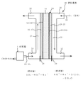
図1は、メタノール等の液体燃料を改質するための改質器1を概略的に示すものである。
【0057】
この改質器1において、筐体2内に設置された改質部3は、液体燃料として例えばメタールと水との混合液を水素と二酸化炭素に分解するための改質触媒層4と、発生した水素は透過するがメタノールは透過させない例えばPd薄膜5との一体化物からなる。このPd薄膜5はカーボンペーパー等の多孔質基板6に密着して設けられる。
【0058】
そして、この改質器1は、後述の発電部としての燃料電池の燃料極(第1極)側に接続して設けられ、得られた水素ガスが燃料極側に供給される。このPd薄膜5は、液体不透過性と水素選択透過性のためには、緻密であってサブμm以下の膜厚に形成されることが望ましい。
【0059】
図2は、図1に示した改質触媒層4の更に外側に、カーボン多孔質シート7を設置した例である(但し、筐体2は図示省略)。このカーボンシート7は、その撥水性のために、液体燃料の分解によって生成する二酸化炭素を効果的に外部に放出することができるので、図1の改質部の優れた作用効果に加えて、二酸化炭素による目づまりを防止し、その触媒活性を維持する上で有利である。
【0060】
発電部としての燃料電池40は、図3に示すように、触媒18及び22をそれぞれ密着又は分散させた互いに対向する、端子28及び29付きの負極(燃料極又は水素極)19及び正極(酸素極)23を有し、これらの両極間にプロトン伝導体膜14が挟着されたMEAを有している。使用時には、負極19側では導入口24を通して改質器1から取り出された水素25が供給され、排出口26(これは設けないこともある。)から排出される。燃料(H2)25が流路27を通過する間にプロトンを発生し、このプロトンはプロトン伝導体膜14で発生したプロトンとともに正極23側へ移動し、そこで導入口30から流路31に供給されて排気口32へ向かう酸素(空気)33と反応し、これにより所望の起電力が取り出される。
【0061】
この燃料電池におけるMEA部(発電部)34は、例えば図4に示すように、カーボンシート16上に形成したガス拡散層17に密着して設けた触媒層(ガス拡散電極)18からなる燃料極(第1極)19と、例えばカーボンシート20上に形成したガス拡散層21に密着して設けた触媒層(ガス拡散電極)22からなる酸素極(第2極)23との間に、イオン(プロトン)伝導体膜14が挟持されてなるMEAによって構成されていてよい。
【0062】
このMEAに用いるイオン(プロトン)伝導体膜14は、パーフルオロスルホン酸樹脂(例えばデュポン社製のナフィオン)等を用いることができる。
【0063】
この燃料電池40によれば、例えば、改質器1に液体燃料として供給されるメタノールは、Pd合金薄膜5により遮断されるため、イオン伝導体膜14に接することなしに改質触媒層4により水素及び二酸化炭素に分解される。ここで生成した水素はPd合金薄膜5、多孔質基板6を透過し、発電部34に導かれ、更に触媒層18によりプロトンを発生し、このプロトンは通常の水素燃料電池と同様にしてイオン伝導体膜14を透過し、酸素極側の触媒層22で水を生成させる。
【0064】
こうして、液体燃料はイオン伝導体膜14に接することがないため、例えばメタノールの濃度を理論値に近づけることができ、また従来提案されているようなSi微細加工プロセスによる改質器を用いるものとは異なり、簡便な手法により、高エネルギー密度の燃料電池を実現できる。
【0065】
なお、改質器1に供給する液体燃料としては、メタノール以外にも、エタノール、プロパノール等のアルコールや、液化天然ガス等が使用可能である。また、燃料電池40の酸素極側には酸素、空気等の酸素含有ガスを供給することができる。
【0066】
上記の改質器1において、改質触媒層4とPd薄膜5との一体化物を作製するには、例えば図5に示す方法を採用するのがよい。
【0067】
まず、図5(a)のように、ガラス基板50上にAlをスパッタにより下地層51として成膜し、この上に、図5(b)のように、Pdをスパッタにより成膜し、液体不透過の水素選択透過膜5を形成する。
【0068】
この上に、図5(c)のように、Al2O3粉体にPtを担持させた粉体と、導電材としてのカーボン粉体と、PVdFからなるバインダとを有機溶媒で混練した後、塗布、乾燥させ、改質触媒層4を形成する。
【0069】
この乾燥後、図5(d)のように、ガラス基板20ごとNaOH溶液に浸し、Al層51を溶解して、改質触媒層4付きのPd薄膜5の単体52を得る。Alのみがアルカリで溶けるため、Pd薄膜5上に塗布膜4が付着した形態となる。
【0070】
そして、図5(e)のように、この単体52を多孔質基板(多孔質カーボンペーパー)6上に設置し、全体を筐体2内に収容する。
【0071】
こうして、触媒層4、水素選択透過層5を一体化した改質器1を得る。この改質器1からガス導管により上記の燃料電池40に接続する。
【0072】
この改質器の製造方法によれば、下地層51上にPd薄膜5をスパッタで形成し、改質触媒層4を塗布形成した後、下地層51を溶解除去しているので、改質触媒層4付きのPd薄膜5を分離する際の応力が殆どなく、膜の機械的強度が小さくても単体52を容易に得ることができ、かつ、得られたPd薄膜5は薄くて緻密で平滑なものとなり、液体不透過の水素選択透過膜を確実に形成することができる。
【0073】
なお、上記の下地層51は、Alに限られず、Al合金等の他の金属も使用可能である。或いは、ポリウレタンを下地層とする場合は、その溶解除去にアセトンを使用する等、下地層の材質と溶媒との組み合せを種々選択することができる。また、溶媒として、NaOH等のアルカリ、HCl等の酸を使用してよい。
【0074】
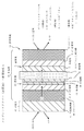
図6に概略図示する燃料電池61は、メタノール等の液体燃料を改質するための改質部(メンブレンリアクター)62を発電部(MEA)63と一体化したものである。
【0075】
改質部62は、液体燃料として例えばメタールと水との混合液を水素と二酸化炭素に分解するための改質触媒層64と、発生した水素は透過するがメタノールは透過させない例えばPd薄膜65との一体化物からなる。そして、このPd薄膜65が発電部63の燃料極(第1極)側に密着して設けられる。このPd薄膜65は、液体不透過性と水素選択透過性のためには、緻密であってサブμm以下の膜厚に形成されることが望ましい。
【0076】
また、発電部63は、例えばカーボンシート66上に形成したガス拡散層67に密着して設けた触媒層(ガス拡散電極)68からなる燃料極(第1極)69と、例えばカーボンシート70上に形成したガス拡散層71に密着して設けた触媒層(ガス拡散電極)72からなる酸素極(第2極)73との間に、イオン(プロトン)伝導体膜74が挟持されてなるMEAによって構成されている。
【0077】
このMEAに用いるイオン(プロトン)伝導体膜74は、パーフルオロスルホン酸樹脂(例えばデュポン社製のナフィオン)等を用いることができる。
【0078】
改質部62を作製するには、例えば、後述するように、基板上にアルカリ溶解性のAlをスパッタにより成膜し、この上にPdをスパッタにより成膜して、液体不透過性の水素透過膜65とし、このPd薄膜65上に、Al2O3(アルミナ)粉体にPt又はPt−Ruを担持させた粉体と導電材としてのカーボン粉体とをPVdFからなるバインダで結着してなる改質触媒層64を塗布する。しかる後に、上記のAl膜をアルカリで溶解除去して、改質触媒層64付きのPd薄膜65の単体を得る。
【0079】
そして、この単体を上記MEAの燃料極側のカーボンシート66に対し、Pd薄膜65側が接するように設置する。こうして、改質触媒層64、水素選択透過性のPd薄膜65及びMEAが一体化した構造体を得る。
【0080】
また、発電部63を作製するには、例えば、後述するように、フッ素系樹脂とカーボン粉体からなる塗料を多孔質カーボンシート66上に塗布して撥水性のカーボン塗布層を作製し、下地層(ガス拡散層)67とし、更にカーボン担持のPt−Ru合金触媒とパーフルオロスルホン酸等のイオン伝導体とからなる塗料を下地層67付きのカーボンシート66上に塗布して、触媒層(燃料極触媒電極)68とする。同様にして、カーボン担持のPt触媒とパーフルオロスルホン酸等のイオン伝導体とからなる塗料を下地層71付きのカーボンシート70上に塗布して、触媒層(酸素極触媒電極)72とする。
【0081】
このようにして作製した酸素極触媒電極72と燃料極触媒電極68とをパーフルオロスルホン酸膜等のイオン伝導体膜74の両側に設置し、ヒートプレスにより加圧接合し、燃料電池用のMEAを作製する。
【0082】
図6に示した燃料電池61によれば、例えば、液体燃料として燃料極側に供給されるメタノールは、Pd合金薄膜65により遮断されるため、イオン伝導体膜74に接することなしに改質触媒層64により水素及び二酸化炭素に分解される。ここで生成した水素はPd合金薄膜65、カーボンシート66及びガス拡散層67を透過し、更に触媒層68によりプロトンを発生し、このプロトンは通常の水素燃料電池と同様にしてイオン伝導体膜74を透過し、酸素極側の触媒層72で水を生成させる。
【0083】
こうして、液体燃料はイオン伝導体膜74に接することがないため、例えばメタノールの濃度を理論値に近づけることができ、また従来提案されているようなSi微細加工プロセスを用いた改質器等を別に設置することなしに、簡便な手法により、高エネルギー密度の燃料電池を実現できる。
【0084】
この燃料電池61は、例えば図7に示すように、外装75a−75b間に装入して燃料電池セルを作製する。燃料極側には燃料供給口76a付きの燃料室77aが形成され、酸素極側には酸素又は空気(空気の場合は大気中に開放してよい)の供給口76b付きの酸素室77bが形成され、両外装75a−75bの周辺部に配したパッキン78によってシールされている。そして、電気化学エネルギーとしての電流は改質触媒層64から取り出し、カーボンシート70との間で構成した閉回路中に外部負荷79を接続し、ここで起電力を取り出すことができる。
【0085】
なお、液体燃料としては、メタノール以外にも、エタノール、プロパノール等のアルコールや、液化天然ガス等が使用可能である。また、酸素極側には酸素、空気等の酸素含有ガスを供給することができる。
【0086】
図8は、図6に示した改質触媒層64の更に外側に、カーボンシート70Aを設置した例である。
【0087】
このカーボンシート70Aは、その撥水性のために、液体燃料の分解によって生成する二酸化炭素を効果的に外部に放出することができるので、図6の燃料電池の優れた作用効果に加えて、二酸化炭素による目づまりを防止し、その触媒活性を維持する上で有利である。
【0088】
図9は、図6に示した燃料電池において、燃料極側のカーボンシート66及びガス拡散層67を省略し、Pd薄膜65を触媒層(燃料電極)68に直接密着させた例である。
【0089】
このように構成すれば、燃料の改質によって生成した水素が触媒層68まで拡散する距離を短くし、かつ燃料電池の薄型化を図ることができる。
【0090】
図10は、図9の燃料電池において、図8の例と同様に改質触媒層64の更に外側に撥水性のカーボンシート70Aを設置した例である。
【0091】
また、図6に示す燃料電池の要部に代えて、図11に示すように、触媒層68中にPd薄膜65を設けてもよい。
【0092】
以上の例において、改質触媒層64とPd薄膜65との一体化物を作製するには、例えば図12及び図13に示す方法を採用するのがよい。
【0093】
まず、図12(a)のように、ガラス基板80上にAlをスパッタにより下地層81として成膜し、この上に、図12(b)のように、Pdをスパッタにより成膜し、液体不透過の水素選択透過膜65を形成する。
【0094】
この上に、図12(c)のように、Al2O3粉体にPtを担持させた粉体と、導電材としてのカーボン粉体と、PVdFからなるバインダとを有機溶媒で混練した後、塗布、乾燥させ、改質触媒層64を形成する。
【0095】
この乾燥後、図12(d)のように、ガラス基板80ごとNaOH溶液に浸し、Al層81を溶解して、改質触媒層64付きのPd薄膜65の単体82を得る。Alのみがアルカリで溶けるため、Pd薄膜65上に塗布膜64が付着した形態となる。
【0096】
そして、図13(e)のように、この単体82を、常法で作製したMEAの燃料極に対しPd薄膜65がMEAの例えばカーボンシート66に接するように密着して設置する。こうして、改質触媒層64、Pd薄膜(水素選択透過層)65及びMEAが一体化した例えば図6の構造体を得る。
【0097】
この方法によれば、下地層81上にPd薄膜65をスパッタで形成し、改質触媒層64を塗布形成した後、下地層81を溶解除去しているので、改質触媒層64付きのPd薄膜65を分離する際の応力が殆どなく、膜の機械的強度が小さくても単体82を容易に得ることができ、かつ、得られたPd薄膜65は薄くて緻密で平滑なものとなり、液体不透過の水素選択透過膜を確実に形成することができる。
【0098】
なお、上記の下地層81は、Alに限られず、Al合金等の他の金属も使用可能である。或いは、ポリウレタンを下地層とする場合は、その溶解除去にアセトンを使用する等、下地層の材質と溶媒との組み合せを種々選択することができる。また、溶媒として、NaOH等のアルカリ、HCl等の酸を使用してよい。
【0099】
【実施例】
以下、本発明の実施例を説明する。
【0100】
実施例1
フッ素系樹脂とカーボン粉体とを水溶液中で混練し、塗料を作製した。この塗料を多孔質カーボンシート上に塗布し、更に不活性ガス中で樹脂の軟化点以上に昇温することにより、カーボンシート上に撥水性のカーボン塗布層を形成し、ガス拡散層とした。
【0101】
次に、カーボン担持のPt−Ru合金触媒をパーフルオロスルホン酸等のイオン伝導体と混練して塗料を作製した。この塗料を上記ガス拡散層付きのカーボンシート上に塗布して、燃料極の触媒電極とした。Pt−Ru量は0.5mg/cm2となるように、塗布量を調整した。
【0102】
同様にして、カーボン担持のPt触媒をパーフルオロスルホン酸等のイオン伝導体と混練して塗料を作製し、この塗料を上記ガス拡散層付きのカーボンシート上に塗布して、酸素極の触媒電極とした。Pt量は0.5mg/cm2となるように塗布量を調整した。
【0103】
このようにして作製した酸素極の触媒電極と燃料極の触媒電極とをパーフルオロスルホン酸膜等のイオン伝導体膜の両側に設置し、ヒートプレスにより加圧接合し、燃料電池用のMEAを作製した。
【0104】
次に、改質器を作製した。即ち、厚さ1mmのガラス基板上に、Alを1000Åの厚さにスパッタにより成膜した。この上に、Pdを5000Åの厚さにスパッタにより成膜し、液体不透過の水素選択透過膜とした。この上に、Al2O3粉体にPtを10重量%担持させた粉体と、導電材としてのカーボン粉体と、PVdFからなるバインダとをNMP(1−メチル−2−ピロリドン)からなる有機溶媒で混練した後、塗布、乾燥させ、改質触媒層を形成した。
【0105】
この乾燥後、ガラス基板ごと5規定のNaOH溶液に浸し、Alを溶解して、改質触媒層付きのPd薄膜の単体を得た。Alのみがアルカリで溶けるため、Pd薄膜上に改質触媒層(塗布膜)が付着した形態となった。
【0106】
これを多孔質基板(多孔質カーボンペーパー)上に設置した。こうして、触媒層、水素選択透過膜が一体化した改質器を得た。この改質器をガス導管により上記の燃料電池に接続した。
【0107】
この燃料電池システムにおいて、改質器に燃料としてメタノールと水をモル比1:1で混合した液体を供給して水素ガスを得、これを燃料極側に供給し、酸素極側に酸素ガスを導入することにより、燃料電池の出力を測定した。この出力を基準値として100とした。
【0108】
比較例1
実施例1のPd薄膜を改質器に設置せずに同様の測定を行った。この場合の出力は、実施例1を100とした場合に比べ、60の低い値しか得られなかった。液体燃料が酸素極まで透過していることが確認された。
【0109】
比較例2
改質器の改質触媒層を多孔質カーボンシート上に塗布し、この上にPdを5000Åの厚さにスパッタにより成膜した。これ以外は実施例1と同様にして改質器を作製し、これを燃料電池に接続し、出力を測定した。この場合の出力は、実施例1を100とした場合に比べ、60の低い値しか得られなかった。液体燃料が酸素極まで透過していることが確認された。Pd薄膜は緻密で平滑に成膜しなければ、液体遮断膜として機能しないことが分った。
【0110】
実施例2
カーボン担持のPt−Ru合金触媒をパーフルオロスルホン酸等のイオン伝導体と混練して塗料を作製し、この塗料をテフロン(登録商標)と称されるPTFE(ポリテトラフルオロエチレン)シート上に塗布、乾燥させた。同様にして、カーボン担持のPt触媒をパーフルオロスルホン酸等のイオン伝導体と混練して塗料を作製し、この塗料を上記のPTFEシート上に塗布、乾燥させた。
【0111】
このようにして作製した酸素極の触媒電極と燃料極の触媒電極とをパーフルオロスルホン酸膜等のイオン伝導体膜の両側に設置し、ヒートプレスにより加圧接合した後、上記のPTFEシートを引き剥がし、いわゆるデカール法により燃料電池用のMEAを作製した。
【0112】
そして、燃料極側に、実施例1と同様に作製した改質器を接続し、酸素極側には実施例1と同様に形成したガス拡散層を設置して、セル構造体を作製した。
【0113】
これを用いて燃料電池セルを作製し、燃料としてメタノールと水をモル比1:1で混合した液体を改質器に供給し、酸素極側に酸素ガスを導入することにより、燃料電池の出力を測定した。この場合の出力は、実施例1を100とした場合、100の同等の出力が得られた。デカール法を用いた場合でも良好な特性が得られた。
【0114】
比較例3
上記のPTFEシート上に、スパッタでPd薄膜を形成し、更にこの上に実施例1で用いたものと同じ改質部用のペーストを塗布し、乾燥した後、このPTFEシートを引き剥がそうとしたところ、塗膜が破断され、改質器として組み上げることは不可能であった。
【0115】
比較例4
改質器を設置することなく、イオン伝導体膜と触媒層(ガス拡散電極)からなるMEAを用いる以外は実施例1と同様にして、燃料電池セルを作製した。燃料としてメタノールと水をモル比1:1で混合した液体を燃料極側に供給し、酸素極側に酸素ガスを導入することにより、燃料電池の出力を測定した。この場合の出力は、実施例1を100とした場合に比べ、初期において10の低い値しか得られず、さらに1時間以内に出力が全く得られなくなった。
【0116】
実施例3
フッ素系樹脂とカーボン粉体とを水溶液中で混練し、塗料を作製した。この塗料を多孔質カーボンシート上に塗布し、更に不活性ガス中で樹脂の軟化点以上に昇温することにより、カーボンシート上に撥水性のカーボン塗布層を形成し、ガス拡散層とした。
【0117】
次に、カーボン担持のPt−Ru合金触媒をパーフルオロスルホン酸等のイオン伝導体と混練して塗料を作製した。この塗料を上記ガス拡散層付きのカーボンシート上に塗布して、燃料極の触媒電極とした。Pt−Ru量は0.5mg/cm2となるように、塗布量を調整した。
【0118】
同様にして、カーボン担持のPt触媒をパーフルオロスルホン酸等のイオン伝導体と混練して塗料を作製し、この塗料を上記ガス拡散層付きのカーボンシート上に塗布して、酸素極の触媒電極とした。Pt量は0.5mg/cm2となるように塗布量を調整した。
【0119】
このようにして作製した酸素極の触媒電極と燃料極の触媒電極とをパーフルオロスルホン酸膜等のイオン伝導体膜の両側に設置し、ヒートプレスにより加圧接合し、燃料電池用のMEAを作製した。
【0120】
次に、改質部を作製した。即ち、厚さ1mmのガラス基板上に、Alを1000Åの厚さにスパッタにより成膜した。この上に、Pdを5000Åの厚さにスパッタにより成膜し、液体不透過の水素選択透過膜とした。この上に、Al2O3粉体にPtを10重量%担持させた粉体と、導電材としてのカーボン粉体と、PVdFからなるバインダとをNMP(1−メチル−2−ピロリドン)からなる有機溶媒で混練した後、塗布、乾燥させ、改質触媒層を形成した。
【0121】
この乾燥後、ガラス基板ごと5規定のNaOH溶液に浸し、Alを溶解して、改質触媒層付きのPd薄膜の単体を得た。Alのみがアルカリで溶けるため、Pd薄膜上に改質触媒層(塗布膜)が付着した形態となった。
【0122】
これを上記のMEAの燃料極に対し、Pd薄膜側がMEAに接するように密着して設置した。こうして、改質触媒層、水素選択透過層及びMEAが一体化した図6に示した如き構造体を得た。
【0123】
これを用いて燃料電池セルを作製し、燃料としてメタノールと水をモル比1:1で混合した液体を燃料極側に供給し、酸素極側に酸素ガスを導入することにより、燃料電池の出力を測定した。この出力を基準値として100とした。
【0124】
比較例5
実施例3のPd薄膜を設置せずに燃料電池セルを作製し、同様の測定を行った。この場合の出力は、実施例3を100とした場合に比べ、60の低い値しか得られなかった。液体燃料が酸素極まで透過していることが確認された。
【0125】
比較例6
改質部の改質触媒層を多孔質カーボンシート上に塗布し、この上にPdを5000Åの厚さにスパッタにより成膜した。これ以外は実施例3と同様にしてMEAと接合し、出力を測定した。この場合の出力は、実施例3を100とした場合に比べ、60の低い値しか得られなかった。液体燃料が酸素極まで透過していることが確認された。Pd薄膜は緻密で平滑に成膜しなければ、液体遮断膜として機能しないことが分った。
【0126】
実施例4
カーボン担持のPt−Ru合金触媒をパーフルオロスルホン酸等のイオン伝導体と混練して塗料を作製し、この塗料をテフロン(登録商標)と称されるPTFE(ポリテトラフルオロエチレン)シート上に塗布、乾燥させた。同様にして、カーボン担持のPt触媒をパーフルオロスルホン酸等のイオン伝導体と混練して塗料を作製し、この塗料を上記のPTFEシート上に塗布、乾燥させた。
【0127】
このようにして作製した酸素極の触媒電極と燃料極の触媒電極とをパーフルオロスルホン酸膜等のイオン伝導体膜の両側に設置し、ヒートプレスにより加圧接合した後、上記のPTFEシートを引き剥がし、いわゆるデカール法により燃料電池用のMEAを作製した。
【0128】
そして、燃料極側に、実施例3と同様に作製した改質部をPd薄膜側で密着して設置し、酸素極側には実施例3と同様に形成したガス拡散層を設置して、図9に示した如きセル構造体を作製した。
【0129】
これを用いて燃料電池セルを作製し、燃料としてメタノールと水をモル比1:1で混合した液体を燃料極側に供給し、酸素極側に酸素ガスを導入することにより、燃料電池の出力を測定した。この場合の出力は、実施例3を100とした場合、100の同等の出力が得られた。デカール法を用いた場合でも良好な特性が得られた。
【0130】
比較例7
上記のPTFEシート上に、スパッタでPd薄膜を形成し、更にこの上に実施例3で用いたものと同じ改質部用のペーストを塗布し、乾燥した後、このPTFEシートを引き剥がそうとしたところ、塗膜が破断され、燃料電池として組み上げることは不可能であった。
【0131】
比較例8
改質部を設置することなく、イオン伝導体膜と触媒層(ガス拡散電極)のみからなるMEAを用いる以外は実施例3と同様にして、燃料電池セルを作製した。燃料としてメタノールと水をモル比1:1で混合した液体を燃料極側に供給し、酸素極側に酸素ガスを導入することにより、燃料電池の出力を測定した。この場合の出力は、実施例3を100とした場合に比べ、初期において10の低い値しか得られず、さらに1時間以内に出力が全く得られなくなった。
【0132】
以上に述べた実施の形態及び実施例は、本発明の技術的思想に基づいて種々に変形可能である。
【0133】
【発明の作用効果】
本発明の燃料改質器によれば、前記液体燃料(例えばメタノールと水)を前記改質器の前記触媒層の側に供給して前記触媒層により前記液体燃料を水素ガスに改質し、この水素は前記水素透過層を通して例えば電気化学デバイスに導入し、ここで目的とする電気化学エネルギーを取り出すことができる。このようにして、液体燃料を電気化学デバイスに供給する前に水素に改質しているので、この液体燃料は高濃度で改質器に供給しても、メタノール等の液体は前記水素透過層によって遮断されるため、前記電気化学デバイスの側へ透過することを十二分に防止することができ、効率良く出力を取り出すことができる。
【0134】
従って、特に改質器を電気化学デバイスとは別に設置した状態で、簡単な構造にて、前記液体燃料を高濃度に供給して効率良く改質できると共に、液体が電気化学デバイスを透過することも同時に防止することができるため、高重量エネルギー密度と高体積エネルギー密度の燃料改質器を簡便に実現することができる。
【0135】
また、本発明の燃料改質器の製造方法によれば、前記水素透過層を得るのに、前記下地層上に前記水素透過層と前記触媒層を形成し、前記下地層を除去しているので、前記水素透過層は前記下地層上に液体不透過性の緻密で平滑な薄膜として形成でき、例えば前記下地層は溶解除去のみによって分離することができる。
【0136】
従って、前記水素透過層は、膜強度を必要以上に大きくしなくても、液体を透過させない緻密で平滑な薄膜であって水素は透過させる薄い膜厚で得ることができ、また前記液体燃料を改質する前記触媒層と一体に形成されるために、前記電気化学デバイスに接続可能な燃料改質器を簡便で効率良く製造することができる。
【0137】
さらに、本発明の電気化学デバイス用電極及びそれを有する電気化学デバイスによれば、液体不透過性であって水素は透過する水素透過層を有するので、例えば前記液体燃料(例えばメタノールと水)を電気化学デバイスの燃料極側に直接供給して前記液体燃料を水素ガスに改質し、得られた前記水素ガスを用いて目的とする電気化学エネルギーを取り出しても、メタノール等の液体は前記水素透過層によって遮断されるため、液体燃料は高濃度で供給することができ、従来例のように前記液体燃料がイオン伝導体を透過することを十二分に防止することができ、効率良く出力を取り出すことができる。
【図面の簡単な説明】
【図1】本発明の実施の形態による燃料改質器の要部の概略断面図である。
【図2】同、他の燃料改質器の要部の概略断面図である。
【図3】同、燃料電池システムの全体の概略図である。
【図4】同、燃料電池の発電部(MEA)の概略断面図である。
【図5】同、燃料改質器の製造方法の各工程における概略断面図である。
【図6】本発明の他の実施の形態による燃料電池の要部の概略断面図である。
【図7】同、燃料電池セルの概略断面図である。
【図8】同、他の燃料電池の概略断面図である。
【図9】同、他の燃料電池の概略断面図である。
【図10】同、更に他の燃料電池の概略断面図である。
【図11】同、更に他の燃料電池の概略断面図である。
【図12】同、燃料電池の製造方法の各工程における概略断面図である。
【図13】同、製造方法の一工程における概略断面図である。
【符号の説明】
1…改質器、2…筐体、3、62…改質部、4、64…改質触媒層、
5、65…Pd薄膜、6…多孔質基板、
7、16、20、66、70、70A…カーボンシート、
14、74…イオン(プロトン)伝導体膜、
17、21、67、71…ガス拡散層、18、68…触媒層(負極)、
19、69…燃料極、22、72…触媒層(正極)、23、73…酸素極、
34、63…発電部、40、61…燃料電池、50、80…基板、
51、81…下地層、52、82…単体(一体化物)[0001]
BACKGROUND OF THE INVENTION
The present invention relates to a fuel reformer that extracts hydrogen from a liquid fuel, a method for manufacturing the same, and an electrochemical device such as an electrode for an electrochemical device and a fuel cell.
[0002]
[Prior art]
As fuel for fuel cells, pure hydrogen sealed in a high-pressure cylinder has been studied mainly for automobiles. In addition, in the stationary type such as cogeneration, reformed gas from methane gas or the like is being studied. As a fuel for a fuel cell for a small device, a technique using hydrogen stored in a hydrogen storage alloy or a liquid fuel such as methanol has been proposed.
[0003]
Here, in the case of using hydrogen stored in a hydrogen storage alloy in a fuel cell for small equipment, it is difficult for the entire system to have a weight energy density that greatly exceeds that of a conventional secondary battery due to the weight of the storage alloy. become. For this reason, when a high weight energy density is required for a fuel cell, it is inappropriate to use the current hydrogen storage alloy.
[0004]
On the other hand, when a liquid fuel such as methanol is used for a fuel cell for a small device, there are a direct methanol method in which methanol is directly introduced into the MEA (Membrane Electrode Assembly) of the fuel cell and a reforming method in which a reformer is separately provided. Proposed.
[0005]
[Problems to be solved by the invention]
In the direct methanol system, methanol and water are theoretically 1: 1 (molar ratio) as fuel, but the ionic conductor also permeates methanol. However, practically, methanol is diluted to a concentration of about 1 mol / l and supplied to the MEA. However, when methanol is diluted to a concentration of about 1 mol / l at the stage of the fuel tank, as in the case of pure hydrogen, it is inappropriate to obtain a high weight energy density for the fuel cell.
[0006]
For this reason, a method of using a higher concentration of methanol in the fuel tank and diluting with water before introducing it into the MEA has been proposed. However, in this method, both methanol and water need to be supplied with high precision, and the liquid supply system becomes complicated and is not suitable for further miniaturization.
[0007]
On the other hand, in a system in which a reformer is separately installed, a higher-concentration methanol solution can be supplied as a fuel, so that the fuel energy density is not reduced, and there is no need to use a complicated liquid supply system. However, when the base material of the reformer is manufactured by microfabrication such as Si as proposed so far, the manufacturing process becomes complicated and the cost increases. Further, the volume is increased by installing the reforming system separately from the MEA.
[0008]
An object of the present invention is to provide a fuel reformer capable of easily realizing a high weight energy density and a high volume energy density, a simple and efficient production method thereof, and an electrode for an electrochemical device such as a fuel cell and an electrochemical device. There is to do.
[0009]
[Means for Solving the Problems]
That is, the present invention has a catalyst layer including a catalyst for extracting hydrogen from liquid fuel, and a hydrogen permeable layer that is liquid impermeable and allows hydrogen to pass therethrough.And the catalyst layer includes a binder and the catalyst.This relates to a fuel reformer.
[0010]
According to the fuel reformer of the present invention, the liquid fuel (for example, methanol and water) is supplied to the catalyst layer side of the reformer to reform the liquid fuel into hydrogen gas by the catalyst layer, This hydrogen can be introduced into, for example, an electrochemical device through the hydrogen permeable layer, and target electrochemical energy can be taken out here. In this way, since the liquid fuel is reformed to hydrogen before being supplied to the electrochemical device, even if this liquid fuel is supplied to the reformer at a high concentration, the liquid such as methanol remains in the hydrogen permeable layer. Therefore, permeation to the electrochemical device side can be sufficiently prevented, and the output can be taken out efficiently.
[0011]
Therefore, in particular, with the reformer installed separately from the electrochemical device, the liquid fuel can be efficiently reformed by supplying a high concentration of the liquid fuel, and the liquid can pass through the electrochemical device. Therefore, it is possible to easily realize a fuel reformer having a high weight energy density and a high volume energy density.
[0012]
Such a fuel reformer of the present invention comprises:
Forming an underlayer on the support;
Forming a hydrogen permeable layer on the underlayer;
On the hydrogen permeable layerIncluding binder and catalystForming a catalyst layer;
Removing the underlayer to obtain an integrated product of the hydrogen permeable layer and the catalyst layer;
It is desirable to manufacture by the manufacturing method of a fuel reformer which has these.
[0013]
A step of forming an underlayer on the support; a step of forming a hydrogen-permeable layer on the underlayer; and on the hydrogen-permeable layerIncluding binder and catalystA step of forming a catalyst layer; and a step of removing the base layer to obtain an integrated product of the hydrogen permeable layer and the catalyst layer; It is desirable to manufacture by the manufacturing method of a fuel reformer which provides the catalyst electrode which has the catalyst layer which consists of these integrally with the said fuel reforming part.
[0014]
According to the manufacturing method of the present invention, in order to obtain the hydrogen permeable layer, the hydrogen permeable layer and the catalyst layer are formed on the underlayer, and the underlayer is removed. It can be formed as a liquid-impermeable dense and smooth thin film on the underlayer. For example, the underlayer can be separated only by dissolution and removal.
[0015]
Therefore, the hydrogen permeable layer is a dense and smooth thin film that does not allow liquid to permeate without increasing the film strength more than necessary, and can be obtained with a thin film thickness that allows hydrogen to pass through. Since it is formed integrally with the catalyst layer to be reformed, a fuel reformer that can be connected to the electrochemical device can be easily and efficiently manufactured.
[0016]
Further, the present invention has a hydrogen permeable layer which is liquid impermeable and allows hydrogen to pass therethrough.And a catalyst layer including a catalyst for extracting hydrogen from the liquid fuel, and the catalyst layer includes a binder and the catalyst.The present invention relates to an electrochemical device electrode, and further relates to an electrochemical device having the electrochemical device electrode of the present invention.
[0017]
According to the electrode for an electrochemical device and the electrochemical device having the same according to the present invention, since it has a hydrogen-permeable layer that is impermeable to liquid and permeable to hydrogen, for example, the liquid fuel (for example, methanol and water) is electrochemically treated. Even if the liquid fuel is reformed to hydrogen gas by supplying directly to the fuel electrode side of the device and the target electrochemical energy is taken out using the obtained hydrogen gas, the liquid such as methanol is still in the hydrogen permeable layer. Therefore, the liquid fuel can be supplied at a high concentration, and the liquid fuel can be sufficiently prevented from passing through the ionic conductor as in the conventional example, and the output can be efficiently taken out. be able to.
[0018]
DETAILED DESCRIPTION OF THE INVENTION
In the fuel reformer of the present invention, a catalyst layer that generates hydrogen from liquid fuel and a hydrogen-permeable layer that selectively permeates hydrogen and does not permeate liquid fuel are indispensable.
[0019]
The thickness of the hydrogen permeable layer that is impermeable to liquid as described above but permeates hydrogen is preferably 2 μm or less (this applies to the electrode for an electrochemical device and the electrochemical device of the present invention). When it exceeds 2 μm, for example, the cost of the noble metal constituting the hydrogen permeable layer described later increases, and there is a possibility that it cannot be used for a small device. Further, the hydrogen permeability is deteriorated, and sufficient hydrogen permeability cannot be obtained unless the temperature is increased to, for example, 100 ° C. or higher. This thickness is preferably 1.5 to 0.3 μm.
[0020]
Further, the catalyst layer and the hydrogen permeable layer may be integrated.
[0021]
The hydrogen permeable layer is preferably made of a material containing a noble metal, and examples of the noble metal include at least one of platinum, palladium, gold, iridium, silver, rhodium, and ruthenium.
[0022]
Here, in order not to allow liquid to pass through, the film of Pd (palladium) alloy or the like that forms the hydrogen permeable layer needs to be dense, but the liquid impervious film and the portion in contact with the film are permeable to hydrogen. A dense structure is unsuitable. However, when Pd or the like is used as a single foil (foil), a film thickness of several tens of μm or more is required, which is a problem in terms of cost and hydrogen permeability. Therefore, it is necessary to produce a thin film such as a dense Pd alloy sandwiched between the porous bodies.
[0023]
Therefore, based on the method for manufacturing a fuel reformer of the present invention, a film that is dissolved in an acid, alkali, or organic solvent is formed on a substrate as a base, and a thin film of a noble metal such as a Pd alloy is formed thereon. Furthermore, a catalyst layer for extracting hydrogen from the liquid fuel is formed by forming a catalyst layer for extracting hydrogen from the liquid fuel, and dissolving and removing the base material with an acid, alkali or organic solvent. Is obtained as a simple substance (integrated with a noble metal thin film), and then the surface of the noble metal thin film is preferably placed on the porous substrate.
[0024]
At this time, the binder of the coating layer (catalyst layer) needs to be chemically stable, and an organic binder containing fluorine such as PVdF (polyvinylidene fluoride) is suitable, and an ion conductive organic binder containing fluorine. Is more preferable.
[0025]
Thereby, since liquid fuel is interrupted | blocked by noble metal thin films, such as Pd alloy, it does not touch the ion conductor film | membrane of an electrochemical device, and is decomposed | disassembled into hydrogen and a carbon dioxide by a reforming catalyst. The hydrogen produced here permeates through a thin film such as a Pd alloy, and further generates protons by the catalyst of the electrochemical device. The protons permeate the ion conductor membrane in the same manner as in a normal hydrogen fuel cell, and oxygen Water is produced by the catalyst on the extreme side.
[0026]
In this case, since the liquid fuel does not come into contact with the ion conductor membrane, the concentration of, for example, methanol supplied to the reformer can be brought close to the theoretical value. In this way, a fuel cell with a high energy density can be realized by a simple method, unlike the case of using a reformer based on a Si microfabrication process as conventionally proposed.
[0027]
From the above, in the present invention, the hydrogen permeable layer is a noble metal film made of at least one of platinum, palladium, gold, iridium, silver, rhodium and ruthenium, such as Pd, Pd-V, Pd-Ag, or It should be made of Pt (which can eliminate embrittlement by hydrogen).
[0028]
Further, the catalyst layer for reforming is made of a material containing a platinum group element (ruthenium, rhodium, palladium, osmium, iridium and platinum), for example, Pt, Pt-Ru, and these are ceramics such as alumina or fine particle carbon powder. It should be carried on the body. In addition, CuO—ZnO may be used, which is preferably supported on ceramics such as alumina.
[0029]
As described above, when ceramics or fine particle carbon powder is used as the support, the catalyst is more activated, which is advantageous for the catalytic action. Further, for example, when Pt—Ru is used as a catalyst, hydrogen can be efficiently generated by oxidative decomposition of liquid fuel with Pt, and at the same time, deterioration of Pt due to CO generated can be prevented with Ru.
[0030]
This catalyst layer is preferably made of a catalyst fixed by a fluorine-based organic binder such as PVdF.
[0031]
The catalyst layer may contain a carbon porous material.
[0032]
In the method for producing a fuel reformer of the present invention, a material that can be dissolved by an acid, an alkali, or an organic solvent, for example, aluminum or an aluminum-based alloy is formed on the support as the base layer, Forming a noble metal film as the hydrogen permeable layer, forming the catalyst layer on the hydrogen permeable layer, and then dissolving and removing the underlayer with an acid, an alkali or an organic solvent. It is preferable that the catalyst layer integrally having the above is obtained as a single body, and the surface of the single noble metal film is placed on a porous substrate such as carbon.
[0033]
The electrode for an electrochemical device of the present invention is characterized in that it has a hydrogen-permeable layer that is impermeable to liquid and permeable to hydrogen, and further includes a catalyst layer that contains a catalyst for extracting hydrogen from the liquid fuel. It is desirable that the hydrogen permeation layer and the catalyst layer may be integrated.
[0034]
It is important that the electrochemical device of the present invention has the above-described electrode for an electrochemical device according to the present invention. For example, a first conductor, a second electrode, and a proton conductor sandwiched between these two electrodes It is desirable that the hydrogen extracted from the reformer is supplied to the first electrode side.
[0035]
In this case, each of the first electrode and the second electrode is fixed to an organic binder such as perfluorosulfonic acid with a platinum-based noble metal such as Pt-Ru or Pt supported on conductive fine particles such as carbon. It can be produced as a gas diffusion electrode.
[0036]
In this case, the gas diffusion electrode is preferably provided in close contact with a gas diffusion layer made of a water-repellent carbon layer formed on a porous carbon sheet. Both layers have gas diffusibility, and the carbon sheet functions as a support and a current collector, and at the same time, due to its water repellency, oxygen is permeated to the catalyst layer on the second electrode side, and water is generated. Can be effectively released to the outside.
[0037]
Further, if a carbon porous layer such as a carbon sheet as described above is disposed outside the catalyst layer of the fuel reformer, the CO generated on the catalyst layer side is formed.2Can be effectively released to the outside and can also have a function as a support.
[0038]
The electrochemical device of the present invention is configured as a fuel cell, wherein hydrogen from the reformer is supplied to the first electrode side, oxygen or an oxygen-containing gas is supplied to the second electrode side, and the first electrode It is desirable that an electrochemical energy such as an electromotive force be extracted from between the electrode and the second electrode.
[0039]
On the other hand, in the electrochemical device of the present invention, particularly a fuel cell, a reforming section for extracting hydrogen from a liquid fuel such as methanol may be installed integrally with the MEA, and the liquid fuel is placed on the ion (proton) conductor membrane. In order not to make it close, the hydrogen permeable layer which is impermeable to liquid but permeable to hydrogen, such as a Pd alloy thin film, is provided.
[0040]
As a method for producing an electrochemical device according to the present invention, after forming a film on a substrate with a material dissolved by an acid, alkali or organic solvent as a base, a thin film of a noble metal such as a Pd alloy is formed thereon, The catalyst layer for extracting hydrogen from the liquid fuel is formed by forming a catalyst layer for extracting hydrogen from the liquid fuel, and dissolving and removing the base material with an acid, alkali, or organic solvent. It is desirable to install the surface of the noble metal thin film on the fuel electrode (first electrode) side of the MEA of the fuel cell.
[0041]
At this time, the binder of the coating layer (catalyst layer) needs to be chemically stable, and a fluorine resin such as PVdF (polyvinylidene fluoride) is preferable. When electrically connecting to the oxygen electrode (second electrode) side through the reforming section, the ceramic-supported catalyst is used to reduce the electric resistance of the reforming section (and also to have a function as a current collector). In addition, it is desirable to mix carbon powder or the like for ensuring conductivity.
[0042]
In the electrochemical device of the present invention, as described above, since the liquid fuel is blocked by the noble metal thin film such as Pd alloy, it does not contact the ion conductor film, and is decomposed into hydrogen and carbon dioxide by the reforming catalyst. The The hydrogen produced here permeates through a thin film such as a Pd alloy, and further generates protons by the catalyst. This proton permeates through the ion conductor membrane in the same manner as a normal hydrogen fuel cell, and the catalyst on the oxygen electrode side. To produce water.
[0043]
In this case, since the liquid fuel does not come into contact with the ion conductor film, for example, the concentration of methanol can be brought close to the theoretical value. In this way, a high energy density fuel cell can be realized by a simple method without separately installing a reformer using a Si microfabrication process as conventionally proposed.
[0044]
From the above, in the electrochemical device of the present invention, the hydrogen permeable layer is a noble metal film such as palladium, such as Pd, Pd-V, Pd-Ag, or Pt (this eliminates embrittlement due to hydrogen. ) Is good.
[0045]
Also, the catalyst layer for reforming is made of a noble metal catalyst such as platinum, for example, Pt, Pt-Ru, and these are preferably supported on ceramics such as alumina. In addition, CuO—ZnO may be used, which is preferably supported on ceramics such as alumina.
[0046]
Thus, when ceramics are used as the carrier, the catalyst is more activated, which is advantageous for the catalytic action. Further, for example, when Pt—Ru is used as a catalyst, hydrogen can be efficiently generated by oxidative decomposition of liquid fuel with Pt, and at the same time, deterioration of Pt due to CO generated can be prevented with Ru.
[0047]
The catalyst layer is preferably composed of the above-mentioned supported catalyst (catalyst supported on the support) and conductive powder such as carbon powder for ensuring conductivity.
[0048]
This catalyst layer is preferably made of a catalyst fixed by a fluorine-based organic binder such as PVdF.
[0049]
Each of the first electrode and the second electrode is made of a platinum-based noble metal such as Pt—Ru or Pt supported on conductive fine particles such as carbon, and fixed with an organic binder such as perfluorosulfonic acid. It can be produced as a gas diffusion electrode.
[0050]
In this case, the gas diffusion electrode is preferably provided in close contact with a gas diffusion layer made of a water-repellent carbon layer formed on a carbon sheet. Both layers have gas diffusibility, and the carbon sheet functions as a support and a current collector, and at the same time, due to its water repellency, oxygen is permeated to the catalyst layer on the second electrode side, and water is generated. Can be effectively released to the outside.
[0051]
In this case, the hydrogen permeable layer may be provided in close contact with the carbon sheet on the first electrode side. The gas diffusion layer is provided in close contact with the gas diffusion electrode of the second electrode, the carbon sheet is disposed on an outer surface of the gas diffusion layer, and is in close contact with the gas diffusion electrode of the first electrode. The hydrogen permeable layer may be provided.
[0052]
Further, if a carbon sheet as described above is further disposed outside the catalyst layer on the first electrode side, the CO generated on the first electrode side is formed.2Can be effectively released to the outside, and can also function as a support and a current collector.
[0053]
The electrochemical device according to the present invention is configured as a fuel cell, the liquid fuel such as methanol is supplied to the first electrode side, oxygen or an oxygen-containing gas is supplied to the second electrode side, and the first electrode It is desirable that an electrochemical energy such as an electromotive force be extracted from between the electrode and the second electrode. In this case, the catalyst layer on the first electrode side and the carbon sheet on the second electrode side may be used as a current collector.
[0054]
In the method for producing an electrochemical device of the present invention, a material that can be dissolved by an acid, an alkali, or an organic solvent, for example, aluminum or an aluminum-based alloy is formed on the support as the base layer, and then on the base layer. A noble metal film is formed as the hydrogen permeable layer, the catalyst layer is formed on the hydrogen permeable layer, and then the base layer is dissolved and removed with an acid, an alkali or an organic solvent to form the noble metal film. The integrated catalyst layer may be obtained as a single body, and the surface of the single noble metal film may be disposed on the first electrode side.
[0055]
Next, a preferred embodiment of the present invention will be described with reference to the drawings.
[0056]
FIG. 1 schematically shows a
[0057]
In this
[0058]
The
[0059]
FIG. 2 is an example in which a porous carbon sheet 7 is installed on the further outside of the reforming
[0060]
As shown in FIG. 3, the fuel cell 40 as a power generation unit includes a negative electrode (fuel electrode or hydrogen electrode) 19 and a positive electrode (oxygen electrode) with
[0061]
The MEA section (power generation section) 34 in this fuel cell is a fuel electrode comprising a catalyst layer (gas diffusion electrode) 18 provided in close contact with the
[0062]
For the ion (proton)
[0063]
According to this fuel cell 40, for example, methanol supplied as liquid fuel to the
[0064]
Thus, since the liquid fuel does not come into contact with the
[0065]
In addition to methanol, alcohol such as ethanol or propanol, liquefied natural gas, or the like can be used as the liquid fuel supplied to the
[0066]
In the
[0067]
First, as shown in FIG. 5 (a), Al is sputtered on the
[0068]
On top of this, as shown in FIG.2OThreeThe reforming
[0069]
After this drying, as shown in FIG. 5D, the glass substrate 20 and the glass substrate 20 are immersed in a NaOH solution, the Al layer 51 is dissolved, and the simple substance 52 of the Pd thin film 5 with the reforming
[0070]
Then, as shown in FIG. 5 (e), the single body 52 is placed on the porous substrate (porous carbon paper) 6 and the whole is housed in the
[0071]
Thus, the
[0072]
According to this reformer manufacturing method, the Pd thin film 5 is formed on the underlayer 51 by sputtering, and after the reforming
[0073]
The underlayer 51 is not limited to Al, and other metals such as an Al alloy can also be used. Alternatively, when polyurethane is used as an underlayer, various combinations of the material of the underlayer and the solvent can be selected, such as using acetone for dissolution and removal. Moreover, you may use alkalis, such as NaOH, and acids, such as HCl, as a solvent.
[0074]
A fuel cell 61 schematically illustrated in FIG. 6 is obtained by integrating a reforming unit (membrane reactor) 62 for reforming liquid fuel such as methanol with a power generation unit (MEA) 63.
[0075]
The reforming unit 62 includes, for example, a reforming catalyst layer 64 for decomposing a mixed liquid of methanol and water as liquid fuel into hydrogen and carbon dioxide, and a Pd thin film 65 that transmits generated hydrogen but does not transmit methanol. It consists of an integrated product. The Pd thin film 65 is provided in close contact with the fuel electrode (first electrode) side of the
[0076]
The
[0077]
As the ion (proton) conductor film 74 used for the MEA, perfluorosulfonic acid resin (for example, Nafion manufactured by DuPont) or the like can be used.
[0078]
In order to fabricate the modified portion 62, for example, as will be described later, an alkali-soluble Al film is formed on a substrate by sputtering, and Pd is formed thereon by sputtering to form a liquid-impermeable hydrogen. A permeable film 65 is formed on the Pd thin film 65.2OThreeA reforming catalyst layer 64 formed by binding a powder in which Pt or Pt-Ru is supported on (alumina) powder and a carbon powder as a conductive material with a binder made of PVdF is applied. Thereafter, the Al film is dissolved and removed with an alkali to obtain a single Pd thin film 65 with the reforming catalyst layer 64.
[0079]
And this single body is installed so that the Pd thin film 65 side contacts the
[0080]
In order to produce the
[0081]
The oxygen electrode catalyst electrode 72 and the fuel electrode catalyst electrode 68 produced in this way are placed on both sides of an ion conductor film 74 such as a perfluorosulfonic acid film, and are pressure bonded by heat press to form an MEA for a fuel cell. Is made.
[0082]
According to the fuel cell 61 shown in FIG. 6, for example, methanol supplied to the fuel electrode side as liquid fuel is blocked by the Pd alloy thin film 65, so that the reforming catalyst is not in contact with the ion conductor film 74. Layer 64 decomposes into hydrogen and carbon dioxide. The hydrogen generated here passes through the Pd alloy thin film 65, the
[0083]
Thus, since the liquid fuel does not come into contact with the ion conductor film 74, for example, the concentration of methanol can be brought close to the theoretical value, and a reformer using a Si microfabrication process as conventionally proposed can be used. A high energy density fuel cell can be realized by a simple method without installation separately.
[0084]
For example, as shown in FIG. 7, the fuel cell 61 is inserted between the exteriors 75a and 75b to produce a fuel cell. A fuel chamber 77a with a fuel supply port 76a is formed on the fuel electrode side, and an oxygen chamber 77b with an oxygen or air supply port 76b is formed on the oxygen electrode side (which may be opened to the atmosphere in the case of air). It is sealed with a packing 78 disposed on the periphery of both exteriors 75a-75b. And the electric current as electrochemical energy is taken out from the reforming catalyst layer 64, an external load 79 is connected in a closed circuit formed between the
[0085]
In addition to methanol, alcohol such as ethanol or propanol, liquefied natural gas, or the like can be used as the liquid fuel. Further, an oxygen-containing gas such as oxygen or air can be supplied to the oxygen electrode side.
[0086]
FIG. 8 shows an example in which a
[0087]
Since this
[0088]
FIG. 9 is an example in which the
[0089]
If comprised in this way, the distance which the hydrogen produced | generated by the reforming | restoration of a fuel diffuses to the catalyst layer 68 can be shortened, and thickness reduction of a fuel cell can be achieved.
[0090]
FIG. 10 is an example in which a water-
[0091]
Further, instead of the main part of the fuel cell shown in FIG. 6, a Pd thin film 65 may be provided in the catalyst layer 68 as shown in FIG.
[0092]
In the above example, in order to produce an integrated product of the reforming catalyst layer 64 and the Pd thin film 65, for example, the method shown in FIGS. 12 and 13 may be employed.
[0093]
First, as shown in FIG. 12A, Al is sputtered on the glass substrate 80 as a base layer 81, and Pd is sputtered thereon as shown in FIG. An impermeable hydrogen selective permeable membrane 65 is formed.
[0094]
On top of this, as shown in FIG.2OThreeThe reformed catalyst layer 64 is formed by kneading a powder in which Pt is supported on a powder, a carbon powder as a conductive material, and a binder made of PVdF with an organic solvent, followed by coating and drying.
[0095]
After this drying, as shown in FIG. 12D, the glass substrate 80 and the glass substrate 80 are immersed in a NaOH solution to dissolve the Al layer 81, thereby obtaining a simple substance 82 of the Pd thin film 65 with the reforming catalyst layer 64. Since only Al is dissolved by alkali, the coating film 64 is attached on the Pd thin film 65.
[0096]
Then, as shown in FIG. 13 (e), the single body 82 is placed in close contact with the fuel electrode of the MEA manufactured by a conventional method so that the Pd thin film 65 is in contact with, for example, the
[0097]
According to this method, the Pd thin film 65 is formed on the underlayer 81 by sputtering, and after the reforming catalyst layer 64 is applied and formed, the underlayer 81 is dissolved and removed. There is almost no stress at the time of separating the thin film 65, and the simple substance 82 can be easily obtained even if the mechanical strength of the film is small, and the obtained Pd thin film 65 becomes thin, dense and smooth, An impermeable hydrogen selective permeable membrane can be reliably formed.
[0098]
The underlayer 81 is not limited to Al, and other metals such as an Al alloy can also be used. Alternatively, when polyurethane is used as an underlayer, various combinations of the material of the underlayer and the solvent can be selected, such as using acetone for dissolution and removal. Moreover, you may use alkalis, such as NaOH, and acids, such as HCl, as a solvent.
[0099]
【Example】
Examples of the present invention will be described below.
[0100]
Example 1
A fluororesin and carbon powder were kneaded in an aqueous solution to prepare a paint. This paint was applied on the porous carbon sheet, and further heated to a temperature higher than the softening point of the resin in an inert gas, thereby forming a water-repellent carbon coating layer on the carbon sheet to obtain a gas diffusion layer.
[0101]
Next, a carbon-supported Pt—Ru alloy catalyst was kneaded with an ion conductor such as perfluorosulfonic acid to prepare a paint. This paint was applied on the carbon sheet with the gas diffusion layer to obtain a fuel electrode catalyst electrode. The amount of Pt-Ru is 0.5 mg / cm2The coating amount was adjusted so that
[0102]
Similarly, a carbon-supported Pt catalyst is kneaded with an ion conductor such as perfluorosulfonic acid to prepare a paint, and this paint is applied onto the carbon sheet with the gas diffusion layer to form an oxygen electrode catalyst electrode. It was. Pt amount is 0.5mg / cm2The coating amount was adjusted so that
[0103]
The oxygen electrode catalyst electrode and the fuel electrode catalyst electrode thus prepared were placed on both sides of an ion conductor film such as a perfluorosulfonic acid film, and pressure bonded by heat press to form an MEA for a fuel cell. Produced.
[0104]
Next, a reformer was produced. That is, Al was formed into a film with a thickness of 1000 mm on a 1 mm thick glass substrate by sputtering. On top of this, Pd was deposited to a thickness of 5000 mm by sputtering to obtain a hydrogen-impervious hydrogen permselective membrane. On top of this, Al2OThreeA powder in which 10% by weight of Pt is supported on a powder, a carbon powder as a conductive material, and a binder made of PVdF are kneaded with an organic solvent made of NMP (1-methyl-2-pyrrolidone), and then applied. And dried to form a reforming catalyst layer.
[0105]
After this drying, the glass substrate was immersed in a 5N NaOH solution to dissolve Al, and a simple Pd thin film with a reforming catalyst layer was obtained. Since only Al was dissolved by alkali, the reforming catalyst layer (coating film) was attached on the Pd thin film.
[0106]
This was installed on a porous substrate (porous carbon paper). Thus, a reformer in which the catalyst layer and the hydrogen permselective membrane were integrated was obtained. This reformer was connected to the fuel cell by a gas conduit.
[0107]
In this fuel cell system, a liquid in which methanol and water are mixed at a molar ratio of 1: 1 as a fuel is supplied to the reformer to obtain hydrogen gas, which is supplied to the fuel electrode side, and oxygen gas is supplied to the oxygen electrode side. The fuel cell output was measured by introducing the fuel cell. This output was set to 100 as a reference value.
[0108]
Comparative Example 1
The same measurement was performed without installing the Pd thin film of Example 1 in the reformer. As for the output in this case, only a low value of 60 was obtained compared to the case where Example 1 was set to 100. It was confirmed that the liquid fuel permeated to the oxygen electrode.
[0109]
Comparative Example 2
The reforming catalyst layer of the reformer was applied on the porous carbon sheet, and Pd was formed thereon by sputtering to a thickness of 5000 mm. Other than this, a reformer was produced in the same manner as in Example 1, and this was connected to a fuel cell, and the output was measured. As for the output in this case, only a low value of 60 was obtained compared to the case where Example 1 was set to 100. It was confirmed that the liquid fuel permeated to the oxygen electrode. It has been found that the Pd thin film does not function as a liquid blocking film unless it is dense and smooth.
[0110]
Example 2
A carbon-supported Pt-Ru alloy catalyst is kneaded with an ion conductor such as perfluorosulfonic acid to prepare a paint, and this paint is applied onto a PTFE (polytetrafluoroethylene) sheet called Teflon (registered trademark). , Dried. Similarly, a carbon-supported Pt catalyst was kneaded with an ion conductor such as perfluorosulfonic acid to prepare a paint, and this paint was applied onto the PTFE sheet and dried.
[0111]
The oxygen electrode catalyst electrode and the fuel electrode catalyst electrode thus prepared were placed on both sides of an ion conductor membrane such as a perfluorosulfonic acid membrane, and after pressure bonding by heat press, the PTFE sheet was The MEA for fuel cells was produced by peeling off and using a so-called decal method.
[0112]
A reformer produced in the same manner as in Example 1 was connected to the fuel electrode side, and a gas diffusion layer formed in the same manner as in Example 1 was installed on the oxygen electrode side to produce a cell structure.
[0113]
Using this, a fuel cell is produced, and a liquid in which methanol and water are mixed at a molar ratio of 1: 1 as fuel is supplied to the reformer, and oxygen gas is introduced to the oxygen electrode side, thereby outputting the output of the fuel cell. Was measured. As for the output in this case, when Example 1 is set to 100, an equivalent output of 100 was obtained. Good characteristics were obtained even when the decal method was used.
[0114]
Comparative Example 3
A Pd thin film is formed on the PTFE sheet by sputtering, and further, the same modified portion paste as that used in Example 1 is applied on the PTFE sheet. After drying, the PTFE sheet is peeled off. As a result, the coating film was broken and it was impossible to assemble it as a reformer.
[0115]
Comparative Example 4
A fuel cell was produced in the same manner as in Example 1 except that an MEA composed of an ion conductor membrane and a catalyst layer (gas diffusion electrode) was used without installing a reformer. A liquid in which methanol and water were mixed at a molar ratio of 1: 1 as a fuel was supplied to the fuel electrode side, and oxygen gas was introduced to the oxygen electrode side to measure the output of the fuel cell. In this case, as compared with the case where Example 1 was set to 100, only a low value of 10 was obtained in the initial stage, and further, no output was obtained within one hour.
[0116]
Example 3
A fluororesin and carbon powder were kneaded in an aqueous solution to prepare a paint. This paint was applied on the porous carbon sheet, and further heated to a temperature higher than the softening point of the resin in an inert gas, thereby forming a water-repellent carbon coating layer on the carbon sheet to obtain a gas diffusion layer.
[0117]
Next, a carbon-supported Pt—Ru alloy catalyst was kneaded with an ion conductor such as perfluorosulfonic acid to prepare a paint. This paint was applied on the carbon sheet with the gas diffusion layer to obtain a fuel electrode catalyst electrode. The amount of Pt-Ru is 0.5 mg / cm2The coating amount was adjusted so that
[0118]
Similarly, a carbon-supported Pt catalyst is kneaded with an ion conductor such as perfluorosulfonic acid to prepare a paint, and this paint is applied onto the carbon sheet with the gas diffusion layer to form an oxygen electrode catalyst electrode. It was. Pt amount is 0.5mg / cm2The coating amount was adjusted so that
[0119]
The oxygen electrode catalyst electrode and the fuel electrode catalyst electrode thus prepared were placed on both sides of an ion conductor film such as a perfluorosulfonic acid film, and pressure bonded by heat press to form an MEA for a fuel cell. Produced.
[0120]
Next, a modified part was produced. That is, Al was formed into a film with a thickness of 1000 mm on a 1 mm thick glass substrate by sputtering. On top of this, Pd was deposited to a thickness of 5000 mm by sputtering to obtain a hydrogen-impervious hydrogen permselective membrane. On top of this, Al2OThreeA powder in which 10% by weight of Pt is supported on a powder, a carbon powder as a conductive material, and a binder made of PVdF are kneaded with an organic solvent made of NMP (1-methyl-2-pyrrolidone), and then applied. And dried to form a reforming catalyst layer.
[0121]
After this drying, the glass substrate was immersed in a 5N NaOH solution to dissolve Al, and a simple Pd thin film with a reforming catalyst layer was obtained. Since only Al was dissolved by alkali, the reforming catalyst layer (coating film) was attached on the Pd thin film.
[0122]
This was installed in close contact with the fuel electrode of the MEA so that the Pd thin film side was in contact with the MEA. Thus, a structure as shown in FIG. 6 in which the reforming catalyst layer, the hydrogen selective permeation layer and the MEA were integrated was obtained.
[0123]
Using this, a fuel cell is produced, and a liquid in which methanol and water are mixed at a molar ratio of 1: 1 as fuel is supplied to the fuel electrode side, and oxygen gas is introduced to the oxygen electrode side. Was measured. This output was set to 100 as a reference value.
[0124]
Comparative Example 5
A fuel cell was produced without installing the Pd thin film of Example 3, and the same measurement was performed. The output in this case was only a low value of 60, compared with the case where Example 3 was set to 100. It was confirmed that the liquid fuel permeated to the oxygen electrode.
[0125]
Comparative Example 6
The reforming catalyst layer of the reforming part was applied on the porous carbon sheet, and Pd was formed thereon by sputtering to a thickness of 5000 mm. Except this, it joined to MEA like Example 3, and measured the output. The output in this case was only a low value of 60, compared with the case where Example 3 was set to 100. It was confirmed that the liquid fuel permeated to the oxygen electrode. It has been found that the Pd thin film does not function as a liquid blocking film unless it is dense and smooth.
[0126]
Example 4
A carbon-supported Pt-Ru alloy catalyst is kneaded with an ion conductor such as perfluorosulfonic acid to prepare a paint, and this paint is applied onto a PTFE (polytetrafluoroethylene) sheet called Teflon (registered trademark). , Dried. Similarly, a carbon-supported Pt catalyst was kneaded with an ion conductor such as perfluorosulfonic acid to prepare a paint, and this paint was applied onto the PTFE sheet and dried.
[0127]
The oxygen electrode catalyst electrode and the fuel electrode catalyst electrode thus prepared were placed on both sides of an ion conductor membrane such as a perfluorosulfonic acid membrane, and after pressure bonding by heat press, the PTFE sheet was The MEA for fuel cells was produced by peeling off and using a so-called decal method.
[0128]
Then, on the fuel electrode side, the reformed part prepared in the same manner as in Example 3 was installed in close contact with the Pd thin film side, and on the oxygen electrode side, a gas diffusion layer formed in the same manner as in Example 3 was installed, A cell structure as shown in FIG. 9 was produced.
[0129]
Using this, a fuel cell is produced, and a liquid in which methanol and water are mixed at a molar ratio of 1: 1 as fuel is supplied to the fuel electrode side, and oxygen gas is introduced to the oxygen electrode side. Was measured. As for the output in this case, when Example 3 is set to 100, an equivalent output of 100 was obtained. Even when the decal method was used, good characteristics were obtained.
[0130]
Comparative Example 7
A Pd thin film is formed on the PTFE sheet by sputtering, and further, the same modified portion paste as that used in Example 3 is applied on the PTFE sheet. After drying, the PTFE sheet is peeled off. As a result, the coating film was broken and it was impossible to assemble it as a fuel cell.
[0131]
Comparative Example 8
A fuel cell was produced in the same manner as in Example 3 except that an MEA consisting only of an ion conductor membrane and a catalyst layer (gas diffusion electrode) was used without installing a reforming section. A liquid in which methanol and water were mixed at a molar ratio of 1: 1 as a fuel was supplied to the fuel electrode side, and oxygen gas was introduced to the oxygen electrode side to measure the output of the fuel cell. In this case, as compared with the case where Example 3 was set to 100, only a low value of 10 was obtained in the initial stage, and further, no output was obtained within one hour.
[0132]
The embodiments and examples described above can be variously modified based on the technical idea of the present invention.
[0133]
[Effects of the invention]
According to the fuel reformer of the present invention, the liquid fuel (for example, methanol and water) is supplied to the catalyst layer side of the reformer to reform the liquid fuel into hydrogen gas by the catalyst layer, This hydrogen can be introduced into, for example, an electrochemical device through the hydrogen permeable layer, and target electrochemical energy can be taken out here. In this way, since the liquid fuel is reformed to hydrogen before being supplied to the electrochemical device, even if this liquid fuel is supplied to the reformer at a high concentration, the liquid such as methanol remains in the hydrogen permeable layer. Therefore, permeation to the electrochemical device side can be sufficiently prevented, and the output can be taken out efficiently.
[0134]
Therefore, in particular, with the reformer installed separately from the electrochemical device, the liquid fuel can be efficiently reformed by supplying a high concentration of the liquid fuel, and the liquid can pass through the electrochemical device. Therefore, it is possible to easily realize a fuel reformer having a high weight energy density and a high volume energy density.
[0135]
According to the method for producing a fuel reformer of the present invention, in order to obtain the hydrogen permeable layer, the hydrogen permeable layer and the catalyst layer are formed on the underlayer, and the underlayer is removed. Therefore, the hydrogen permeable layer can be formed as a liquid-impermeable dense and smooth thin film on the underlayer. For example, the underlayer can be separated only by dissolution and removal.
[0136]
Therefore, the hydrogen permeable layer is a dense and smooth thin film that does not allow liquid to permeate without increasing the film strength more than necessary, and can be obtained with a thin film thickness that allows hydrogen to pass through. Since it is formed integrally with the catalyst layer to be reformed, a fuel reformer that can be connected to the electrochemical device can be easily and efficiently manufactured.
[0137]
Furthermore, according to the electrode for an electrochemical device of the present invention and the electrochemical device having the electrode, the liquid fuel impermeable hydrogen permeation layer is provided, so that the liquid fuel (for example, methanol and water) is used, for example. Even if the liquid fuel is reformed to hydrogen gas by supplying it directly to the fuel electrode side of the electrochemical device, and the target electrochemical energy is taken out using the obtained hydrogen gas, the liquid such as methanol is still the hydrogen. Since it is blocked by the permeable layer, the liquid fuel can be supplied at a high concentration, and the liquid fuel can be sufficiently prevented from passing through the ionic conductor as in the conventional example, and the output can be efficiently performed. Can be taken out.
[Brief description of the drawings]
FIG. 1 is a schematic cross-sectional view of a main part of a fuel reformer according to an embodiment of the present invention.
FIG. 2 is a schematic cross-sectional view of the main part of another fuel reformer.
FIG. 3 is a schematic view of the entire fuel cell system.
FIG. 4 is a schematic cross-sectional view of the power generation unit (MEA) of the fuel cell.
FIG. 5 is a schematic cross-sectional view of each step of the fuel reformer manufacturing method.
FIG. 6 is a schematic cross-sectional view of a main part of a fuel cell according to another embodiment of the present invention.
FIG. 7 is a schematic cross-sectional view of the fuel battery cell.
FIG. 8 is a schematic cross-sectional view of another fuel cell.
FIG. 9 is a schematic cross-sectional view of another fuel cell.
FIG. 10 is a schematic sectional view of still another fuel cell.
FIG. 11 is a schematic sectional view of still another fuel cell.
FIG. 12 is a schematic cross-sectional view of each step of the fuel cell manufacturing method.
FIG. 13 is a schematic cross-sectional view in one step of the manufacturing method of the same.
[Explanation of symbols]
DESCRIPTION OF
5, 65 ... Pd thin film, 6 ... porous substrate,
7, 16, 20, 66, 70, 70A ... carbon sheet,
14, 74 ... ion (proton) conductor membrane,
17, 21, 67, 71 ... gas diffusion layer, 18, 68 ... catalyst layer (negative electrode),
19, 69 ... fuel electrode, 22, 72 ... catalyst layer (positive electrode), 23, 73 ... oxygen electrode,
34, 63 ... power generation unit, 40, 61 ... fuel cell, 50, 80 ... substrate,
51, 81 ... Underlayer, 52, 82 ... Single unit (integrated product)
Claims (40)
前記下地層上に水素透過層を形成する工程と、
前記水素透過層上に、バインダと触媒とを含む触媒層を形成する工程と、
前記下地層を除去して、前記水素透過層と前記触媒層との一体化物を得る工程と
を有する、燃料改質器の製造方法。Forming an underlayer on the support;
Forming a hydrogen permeable layer on the underlayer;
Forming a catalyst layer containing a binder and a catalyst on the hydrogen permeable layer;
And a step of removing the underlayer to obtain an integrated product of the hydrogen permeation layer and the catalyst layer.
Priority Applications (5)
| Application Number | Priority Date | Filing Date | Title |
|---|---|---|---|
| JP2003133198A JP4171978B2 (en) | 2002-05-27 | 2003-05-12 | Fuel reformer and manufacturing method thereof, electrode for electrochemical device, and electrochemical device |
| AU2003241764A AU2003241764A1 (en) | 2002-05-27 | 2003-05-26 | Fuel reformer and method of manufacturing the fuel reformer, electrode for electrochemical device, and electrochemical device |
| US10/513,548 US7942944B2 (en) | 2002-05-27 | 2003-05-26 | Fuel reformer and method for producing the same, electrode for use in electrochemical device, and electrochemical device |
| PCT/JP2003/006520 WO2003099711A1 (en) | 2002-05-27 | 2003-05-26 | Fuel reformer and method of manufacturing the fuel reformer, electrode for electrochemical device, and electrochemical device |
| US12/713,999 US8882864B2 (en) | 2002-05-27 | 2010-02-26 | Fuel reformer including a two layer integrated article |
Applications Claiming Priority (3)
| Application Number | Priority Date | Filing Date | Title |
|---|---|---|---|
| JP2002151724 | 2002-05-27 | ||
| JP2002151723 | 2002-05-27 | ||
| JP2003133198A JP4171978B2 (en) | 2002-05-27 | 2003-05-12 | Fuel reformer and manufacturing method thereof, electrode for electrochemical device, and electrochemical device |
Publications (2)
| Publication Number | Publication Date |
|---|---|
| JP2004055519A JP2004055519A (en) | 2004-02-19 |
| JP4171978B2 true JP4171978B2 (en) | 2008-10-29 |
Family
ID=29587461
Family Applications (1)
| Application Number | Title | Priority Date | Filing Date |
|---|---|---|---|
| JP2003133198A Expired - Fee Related JP4171978B2 (en) | 2002-05-27 | 2003-05-12 | Fuel reformer and manufacturing method thereof, electrode for electrochemical device, and electrochemical device |
Country Status (4)
| Country | Link |
|---|---|
| US (2) | US7942944B2 (en) |
| JP (1) | JP4171978B2 (en) |
| AU (1) | AU2003241764A1 (en) |
| WO (1) | WO2003099711A1 (en) |
Families Citing this family (13)
| Publication number | Priority date | Publication date | Assignee | Title |
|---|---|---|---|---|
| WO2006011616A1 (en) * | 2004-07-26 | 2006-02-02 | Ngk Insulators, Ltd. | Reactor |
| JP2006185825A (en) * | 2004-12-28 | 2006-07-13 | Sony Corp | Fuel cell system |
| US7419732B2 (en) * | 2005-02-11 | 2008-09-02 | Gore Enterprise Holdings, Inc. | Method for reducing degradation in a fuel cell |
| EP1986264A1 (en) * | 2007-04-26 | 2008-10-29 | Technische Universität München | System for generating electrical energy comprising an electrochemical reformer and a fuel cell |
| JP2010103033A (en) * | 2008-10-27 | 2010-05-06 | Fujitsu Ltd | Fuel cell |
| WO2011036749A1 (en) * | 2009-09-24 | 2011-03-31 | 株式会社 東芝 | Collector member, power generation device, and method for producing collector member for power generation device |
| FR2952756B1 (en) * | 2009-11-18 | 2011-11-25 | Commissariat Energie Atomique | ELECTRIC GENERATOR THERMOELECTRIC EFFECT WITH IMPLEMENTATION OF TWO CHEMICAL REACTIONS, EXOTHERMIC AND ENDOTHERMIC, FOR RESPECTIVELY GENERATING AND DISSIPATING HEAT |
| CN102823040B (en) * | 2010-03-26 | 2015-03-11 | 凸版印刷株式会社 | Method for manufacturing fuel cell membrane electrode assembly and apparatus for manufacturing fuel cell membrane electrode assembly |
| US20130071764A1 (en) | 2011-09-15 | 2013-03-21 | John R. Budge | Systems and methods for steam reforming |
| CN108036523A (en) * | 2017-11-28 | 2018-05-15 | 深圳信息职业技术学院 | A kind of miniature solar energy heat collector of preparing hydrogen by reforming methanol |
| KR102654789B1 (en) * | 2018-10-23 | 2024-04-05 | 에스케이이노베이션 주식회사 | Separator for secondary battery and electrochemical device using the same |
| DE102021200837A1 (en) | 2021-01-29 | 2022-08-04 | Forschungszentrum Jülich GmbH | Multi-layer coating system, in particular for attachment to a fuel cell, and fuel cell with such a coating system |
| DE102021204452A1 (en) * | 2021-05-04 | 2022-11-10 | Siemens Mobility GmbH | Medium temperature fuel cell with internal reforming and rail vehicle |
Family Cites Families (30)
| Publication number | Priority date | Publication date | Assignee | Title |
|---|---|---|---|---|
| US3765946A (en) * | 1971-08-18 | 1973-10-16 | United Aircraft Corp | Fuel cell system |
| JP2516750B2 (en) | 1986-11-07 | 1996-07-24 | 株式会社リコー | Photoelectric conversion element |
| JPH01154467A (en) * | 1987-12-11 | 1989-06-16 | Hitachi Ltd | Liquid fuel cell |
| JP2516750Y2 (en) * | 1990-04-12 | 1996-11-13 | 三菱重工業株式会社 | Assembly of solid polymer electrolyte membrane and electrode |
| JPH06212469A (en) * | 1992-07-16 | 1994-08-02 | Imura Japan Kk | Gas diffusion electrode and electrochemical reactor using the electrode |
| JP3328993B2 (en) | 1993-05-10 | 2002-09-30 | 住友電気工業株式会社 | Hydrogen generation method |
| US5430218A (en) * | 1993-08-27 | 1995-07-04 | Chevron U.S.A. Inc. | Dehydrogenation using dehydrogenation catalyst and polymer-porous solid composite membrane |
| FR2718979B1 (en) * | 1994-04-20 | 1996-06-07 | Air Liquide | Method for restarting a hydrogen purification container by adsorption, and its application to the treatment of certain gases containing hydrogen. |
| JP3599370B2 (en) * | 1994-05-23 | 2004-12-08 | 日本碍子株式会社 | Hydrogen production equipment |
| JPH08321321A (en) | 1995-05-24 | 1996-12-03 | Tokyo Gas Co Ltd | Fuel cell |
| US6183898B1 (en) * | 1995-11-28 | 2001-02-06 | Hoescht Research & Technology Deutschland Gmbh & Co. Kg | Gas diffusion electrode for polymer electrolyte membrane fuel cells |
| US5753385A (en) * | 1995-12-12 | 1998-05-19 | Regents Of The University Of California | Hybrid deposition of thin film solid oxide fuel cells and electrolyzers |
| JPH10265202A (en) * | 1997-03-25 | 1998-10-06 | Ishikawajima Harima Heavy Ind Co Ltd | Hydrogen producing device |
| DE19720294C1 (en) * | 1997-05-15 | 1998-12-10 | Dbb Fuel Cell Engines Gmbh | Reforming reactor and operating procedures therefor |
| JP4259654B2 (en) * | 1998-10-22 | 2009-04-30 | 株式会社豊田中央研究所 | Carbon monoxide reduction catalyst |
| WO2000032512A1 (en) * | 1998-12-02 | 2000-06-08 | Massachusetts Institute Of Technology | Integrated palladium-based micromembranes for hydrogen separation and hydrogenation/dehydrogenation reactions |
| MXPA02000037A (en) * | 1999-06-21 | 2003-01-28 | E Cell Corp | Heterogeneous ion exchange membrane and method of manufacturing thereof. |
| US6536604B1 (en) * | 1999-06-25 | 2003-03-25 | C. Jeffrey Brinker | Inorganic dual-layer microporous supported membranes |
| DE19945667C2 (en) * | 1999-09-23 | 2003-06-26 | Siemens Ag | Fuel cell, method for its operation and associated use |
| JP4601097B2 (en) * | 1999-09-30 | 2010-12-22 | トッパン・フォームズ株式会社 | Form preparation device |
| US6350539B1 (en) * | 1999-10-25 | 2002-02-26 | General Motors Corporation | Composite gas distribution structure for fuel cell |
| JP2001137673A (en) | 1999-11-12 | 2001-05-22 | Sumitomo Electric Ind Ltd | Hydrogen separating composite |
| JP2002033113A (en) * | 1999-11-18 | 2002-01-31 | Toyota Motor Corp | Fuel gas generating device for fuel cell and composite material for hydrogen separation |
| JP2001145825A (en) * | 1999-11-24 | 2001-05-29 | Mitsubishi Kakoki Kaisha Ltd | Method for manufacturing hydrogen separating membrane |
| US6656617B2 (en) * | 2000-01-24 | 2003-12-02 | Toyota Jidosha Kabushiki Kaisha | Fuel gas production system for fuel cells |
| US6436363B1 (en) * | 2000-08-31 | 2002-08-20 | Engelhard Corporation | Process for generating hydrogen-rich gas |
| JP4604332B2 (en) * | 2000-10-27 | 2011-01-05 | トヨタ自動車株式会社 | Reforming composite and hydrogen generating structure provided therewith |
| JP3882567B2 (en) * | 2000-11-24 | 2007-02-21 | 住友電気工業株式会社 | Material separation structure |
| US7081317B2 (en) * | 2001-03-29 | 2006-07-25 | Matsushita Electric Industrial Co., Ltd. | Polymer electrolyte thin film fuel cell and method of operating the same |
| JP3801061B2 (en) * | 2002-02-04 | 2006-07-26 | トヨタ自動車株式会社 | Hydrogen permeable membrane |
-
2003
- 2003-05-12 JP JP2003133198A patent/JP4171978B2/en not_active Expired - Fee Related
- 2003-05-26 AU AU2003241764A patent/AU2003241764A1/en not_active Abandoned
- 2003-05-26 US US10/513,548 patent/US7942944B2/en active Active
- 2003-05-26 WO PCT/JP2003/006520 patent/WO2003099711A1/en active Application Filing
-
2010
- 2010-02-26 US US12/713,999 patent/US8882864B2/en not_active Expired - Lifetime
Also Published As
| Publication number | Publication date |
|---|---|
| AU2003241764A1 (en) | 2003-12-12 |
| US20050176576A1 (en) | 2005-08-11 |
| US20100150796A1 (en) | 2010-06-17 |
| US8882864B2 (en) | 2014-11-11 |
| US7942944B2 (en) | 2011-05-17 |
| JP2004055519A (en) | 2004-02-19 |
| WO2003099711A1 (en) | 2003-12-04 |
Similar Documents
| Publication | Publication Date | Title |
|---|---|---|
| US8882864B2 (en) | Fuel reformer including a two layer integrated article | |
| JP5270098B2 (en) | Improved electrode | |
| CN105609786B (en) | Catalyst layer | |
| JP2000173626A5 (en) | ||
| JP2004006369A (en) | Method for manufacturing membrane electrode assembly using membrane coated with catalyst | |
| JP2003346862A (en) | Fuel cell | |
| JP2008503852A (en) | Fuel cell system | |
| WO2006101132A1 (en) | Fuel cell | |
| EP1192681B1 (en) | Gas diffusion substrate and electrode | |
| JP2002231265A (en) | Fuel cell | |
| JP2006522433A (en) | Membrane electrode integrated structure with catalyst for oxidizing carbon monoxide | |
| JP2006526873A (en) | Membrane electrode unit for direct methanol fuel cell and manufacturing method thereof | |
| WO2010074005A1 (en) | Fuel cell | |
| EP3520160B1 (en) | Multi-layer catalyst design | |
| JP5167670B2 (en) | Solid oxide fuel cell | |
| TWI328899B (en) | ||
| JP2649470B2 (en) | Fuel cell | |
| KR20060096610A (en) | Membrane electrode assembly for fuel cell, and stack for fuel cell and full cell system comprising the same | |
| JP5110835B2 (en) | Catalyst electrode for fuel cell, membrane / electrode assembly using the same, and fuel cell | |
| JP2002110190A (en) | Fuel cell | |
| KR20080110313A (en) | Fuel composition for polymer electrolyte fuel cell polymer electrolyte fuel cell system comprising same | |
| JP5034894B2 (en) | Fuel cell, fuel cell stack and fuel cell system. | |
| JP2008282672A (en) | Fuel cell and its manufacturing method | |
| WO2010053164A1 (en) | Fuel cell | |
| JP2005032520A (en) | Fuel cell and its manufacturing method |
Legal Events
| Date | Code | Title | Description |
|---|---|---|---|
| A621 | Written request for application examination |
Free format text: JAPANESE INTERMEDIATE CODE: A621 Effective date: 20040427 |
|
| RD13 | Notification of appointment of power of sub attorney |
Free format text: JAPANESE INTERMEDIATE CODE: A7433 Effective date: 20070125 |
|
| A131 | Notification of reasons for refusal |
Free format text: JAPANESE INTERMEDIATE CODE: A131 Effective date: 20070618 |
|
| A521 | Written amendment |
Free format text: JAPANESE INTERMEDIATE CODE: A523 Effective date: 20070802 |
|
| TRDD | Decision of grant or rejection written | ||
| A01 | Written decision to grant a patent or to grant a registration (utility model) |
Free format text: JAPANESE INTERMEDIATE CODE: A01 Effective date: 20080717 |
|
| A01 | Written decision to grant a patent or to grant a registration (utility model) |
Free format text: JAPANESE INTERMEDIATE CODE: A01 |
|
| A61 | First payment of annual fees (during grant procedure) |
Free format text: JAPANESE INTERMEDIATE CODE: A61 Effective date: 20080730 |
|
| FPAY | Renewal fee payment (event date is renewal date of database) |
Free format text: PAYMENT UNTIL: 20110822 Year of fee payment: 3 |
|
| FPAY | Renewal fee payment (event date is renewal date of database) |
Free format text: PAYMENT UNTIL: 20120822 Year of fee payment: 4 |
|
| FPAY | Renewal fee payment (event date is renewal date of database) |
Free format text: PAYMENT UNTIL: 20130822 Year of fee payment: 5 |
|
| R250 | Receipt of annual fees |
Free format text: JAPANESE INTERMEDIATE CODE: R250 |
|
| R250 | Receipt of annual fees |
Free format text: JAPANESE INTERMEDIATE CODE: R250 |
|
| LAPS | Cancellation because of no payment of annual fees |