JP4166878B2 - Biosensor used in lancet-integrated body fluid measuring device - Google Patents
Biosensor used in lancet-integrated body fluid measuring device Download PDFInfo
- Publication number
- JP4166878B2 JP4166878B2 JP31402998A JP31402998A JP4166878B2 JP 4166878 B2 JP4166878 B2 JP 4166878B2 JP 31402998 A JP31402998 A JP 31402998A JP 31402998 A JP31402998 A JP 31402998A JP 4166878 B2 JP4166878 B2 JP 4166878B2
- Authority
- JP
- Japan
- Prior art keywords
- biosensor
- contact surface
- skin contact
- puncture
- body fluid
- Prior art date
- Legal status (The legal status is an assumption and is not a legal conclusion. Google has not performed a legal analysis and makes no representation as to the accuracy of the status listed.)
- Expired - Fee Related
Links
Images


Description
【0001】
【発明の属する技術分野】
本願発明は、血中グルコース濃度(以下、「血糖値」という。)等、体液に含まれる被検知物質を測定することができ、なおかつ、皮膚からの体液採集と測定とを一体の操作によって行うことができるバイオセンサに関する。
【0002】
【発明の背景】
糖尿病の治療には、患者の血糖値を正常範囲に保つことが必要であり、患者自らによる血糖値管理が重要な治療法である。とくに、患者自身によるインスリン注射によって血糖値を正常範囲に維持する場合には、患者自身による適宜の血糖値測定が欠かせない。
【0003】
このような目的に使用する携帯型の血糖値測定装置がすでに市販されており、中でも、ランセットとセンサが一体型構造をなすものとして、例えば
特願平10−166894号の特許出願がある。
【0004】
この体液測定装置は、本体と、この本体に装着して使用する装着体とを備えた体液測定装置であって、上記装着体は、皮膚当接面と、この皮膚当接面に沿うように配置されたセンサと、尖端が皮膚当接面から突出する進出位置と尖端が皮膚当接面から没入する退避位置との間を移動可能であり、かつ弾性体によって退避位置側に付勢されている穿刺体とを備えており、上記本体は、上記装着体が装着されたときにこの装着体が備えるセンサの各電極に接触してこれらに導通する端子、この端子を介して得られる電気信号に基づいて測定値を決定する電子回路、および、上記穿刺体を前進駆動してこの穿刺体に進出位置をとらせるための駆動機構を備えている。
【0005】
測定にあたって使用者は、上記装着体を本体に装着する。皮膚当接面を指先や耳たぶ等の皮膚に押し当てながら本体の駆動機構を作動さると、退避位置にある穿刺体が進出させられてその尖端が皮膚当接面から突出し、皮膚に傷を付ける。次の瞬間弾性体の作用によって穿刺体は退避位置に戻る。装置をそのままの状態に保持しておくと、皮膚から流出した血液がセンサに浸透し、センサは反応電流を出力する。この電流は電子回路によって血液中の特定成分濃度に換算され、たとえば本体表面に配置された表示器に表示される。
【0006】
好ましい実施の形態においてはまた、上記装着体におけるセンサは、全体として上記皮膚当接面に沿うように延びる板状を呈しているとともに、その厚み方向の内部に内面に反応部が臨む体液通路が形成されており、かつ、この体液通路に連通するとともに上記穿刺体の尖端が通過可能な貫通穴が形成された構成を備えている。
【0007】
このように構成によれば、穿刺体が通過する貫通穴とセンサ内の体液通路が連通しているので、皮膚につけた傷から流出される血液が直接的に貫通穴に入り込み、引き続いて反応部が臨む体液通路に充満させられる。
【0008】
しかし、上記の特願平10−166894号の特許出願に記載の体液測定装置では、皮膚につけた傷から流出される血液が直接的に貫通穴に入り込む以外に、センサと皮膚の間にできる隙間に入り込むという問題点があった。
【0009】
【発明が解決しようとする課題】
本発明は上記従来の問題点を解決するもので、センサを改良することにより、皮膚につけた傷から流出される血液が確実に直接貫通穴に入り込むセンサを提供することを目的とする。
【0010】
【課題を解決するための手段】
上記の課題を解決するため、鋭意研究の末、装着体におけるセンサにおいて、皮膚に沿うように配置されたセンサの皮膚当接面を疎水化処理を施してあるとともに、上記皮膚当接面における上記穿刺体の突端の移動を許容するための貫通孔のごく近傍周辺部に、疎水性材料を用いて形成した皮膚と皮膚当接面との間に血液が入り込むのを抑制するための立体遮蔽物を配していることを特徴とするバイオセンサである。
【0011】
【実施の形態】
【実施例1】
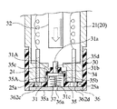
以下、本発明の一実施例について図面を参照しつつ、説明する。図1は、体液測定装置の全体外観図、図2は、穿刺体が退避した状態における装着体の詳細を示す拡大縦断面図であり図4のII−II線に沿う断面に相当する図、図3は、穿刺体が進出した状態における装着体の詳細を示す拡大縦断面図、図4は、装着体の底面図、図5は、センサを外した状態での装着体の底面図である。
【0012】
図1ないし図3に示されるように、体液測定装置10は、本体20と装着体30とを組み合わせて使用される。本体20は、その上面にスイッチボタン類、LCD表示器22などが配置されている。この本体20の前部には筒状部21が延出形成されており、その先端部には、後に詳しく説明するキャップ状の装着体30が装着されている。また、この本体20の内部には、装着体30が備える穿刺体31を前進駆動するための駆動機構(23,32)、および、マイクロコンピュータ等の回路等が内蔵される。図1において符号23は、上記駆動機構の一部を構成し、使用者が手動によって押圧するための押圧部を示している。
【0013】
図2ないし図5に装着体30の一例の詳細を示す。この装着体30は、円筒部34と、この円筒部34の先端を塞ぐように位置する底壁部35とを備える大略キャップ状をしており、その主要部分は樹脂成形によって作製される。円筒部34の内径は、本体20の前部筒状部24の外径と対応させられており、この前部筒状部24に被せるようにして簡便に装着することができる。
【0014】
このキャップ状の装着体30の底壁部35には、穿刺体31と、バイオセンサ36とが一体に組み込まれる。底壁部35には、円筒壁35bと底壁35cとを有する円筒状の陥没部35Aがこの装着体30の中心位置に形成され、この陥没部35Aの底壁35cには、中心孔35dが開けられている。
【0015】
一方、穿刺体31は、上記中心孔35dにスライド可能に嵌合するガイド軸部31aとこのガイド軸部31aの一端に一体形成されたフランジ部31bとを有する樹脂製のガイド体31Aに金属製の穿刺針31cを一体にインサートした形態をもっており、フランジ部31bと後述する板状バイオセンサ36の上面との間に介装された弾性体37により、常時図2に示す退避位置、すなわち、フランジ部31bが陥没部35Aの底壁35cに当接する位置に向けて付勢されている。この退避位置において、ガイド軸部31aの後端は底壁35cの内側に突出した状態となり、穿刺針31cは、後述する板状バイオセンサ36の裏側に退避した状態となる。上記のように穿刺体31を退避位置に向けて付勢する弾性体37の態様としては、図2および図3に示されるように金属あるいは樹脂でできた圧縮コイルバネを用いる。
【0016】
装着体30の底壁部35にはまた、上記穿刺体31が収容された陥没部35Aを覆うようにして、板状バイオセンサ36が貼着される。このバイオセンサ36は、図6ないし図8に示したように穿刺体31の穿刺針31cが通過しうる貫通孔36aと、この貫通孔36aと連通して厚みのなかを底壁部35と平行に延びる体液通路36bを備え、この体液通路36bの内壁に反応部36kが形成された構成を備えている。
【0017】
より具体的には、このバイオセンサ36は、上面に作用極36cおよび対極36dが膜形成された絶縁ベース板36Aと、作用極36cおよび対極36dの一部を露出させる溝36eを形成するように絶縁ベース板36A上に積層された板状スペーサ36B,36Bと、この板状スペーサ36B,36Bにさらに積層された板状カバー36Cとを備えている。以下、この板状バイオセンサ36の作製工程を説明する。
【0018】
図9に示すように、たとえば0.2mmの厚みをもつ樹脂製絶縁シートからなる平面視長矩形状のベース板36Aが準備される。このベース板36Aにおいて電極が形成される面とは相対する平行面、すなわち皮膚当接面部分を図10に示す。図10に示すように、少なくとも貫通孔 36 aのごく近傍周辺部をあらかじめ疎水化処理を行って疎水部 363 aを形成してある。ここで言う、疎水化処理とは、水とのなじみを悪化させることである。ここで、疎水化処理するための化合物としては、樹脂製絶縁シートの表面を疎水化または撥水化できるものであれば特に限定されないが、例えばポリウレタン系樹脂、ポリアクリル系樹脂、ポリエステル系樹脂、ポリアミド系樹脂、ポリ塩化ビニル系樹脂、ポリスチレン系樹脂、フッ素系樹脂、その他ゴム変性物などが挙げられ、特に水溶性の樹脂とか吸湿性の高い樹脂でない限り、従来、インキのバインダーなどに使用されている公知の樹脂はいずれも使用することができる。また疎水化処理の方式としては、例えば上記樹脂を主成分とする液を所定の部分に浸透させた後乾燥させることによる印刷方式や撥水剤のコーティングなど公知の技術はいすれも使用することができる。このベース板36Aには、あらかじめたとえば1.5mm径の貫通孔 36aが形成されている。このベース板36Aの上面には、グラファイトインクを用いたスクリーン印刷の手法により、作用極36cと対極36dとが膜状に形成される。作用極36cは、端子部となるべき端部領域36f(作用極36cに斜線のみを施した領域)から細状の突出部36gが延出形成された平面形態をもち、一方、対極36dは、端子部となるべき端部領域36h(対極36dに斜線のみを施した領域)から上記作用極36c側の突出部36gを両側から挟むように二股状に延びる突出部36i,36iをもつ平面形態をもっている。貫通孔 36aは、対極36dの一方の突出部36iと近接して位置している。
【0019】
次に、作用極36cおよび対極36dの各突出部36g,36i,36iが縦方向に並ぶ帯状領域と、作用極36cおよび対極36dの各端部領域36f,36hを残してレジスト層36j(実線と一点鎖線で斜線を施した領域)を印刷形成する。
【0020】
続いて、上記レジスト層36jに重ねるようにして、レジスト層36jと同等の平面形状を有するスペーサ板36B,36Bを配置する。このスペーサ板36Bとしては、たとえば厚み0.2mmの樹脂製の板が採用され、表裏面に粘着剤層を設けた両面テープ態様のものが使用される。これにより、スペーサ板36B,36Bで挟まれる凹溝36eが形成され(図8参照)、かつこの凹溝36eの底部の帯状の領域に上記作用極36cと対極36dの各突出部36g,36i,36iが並んで露出する格好となる。なお、上記凹溝36eの幅は、たとえば1.5mm、長さはたとえば3mmに設定される。
【0021】
次に、上記凹溝36eの底部の帯状の領域に、図8に良く表れているような反応試薬層36kを形成する。血糖値測定用のセンサとして構成する場合、この反応試薬は、酸化酵素であるグルコースオキシターゼおよびメディエータとしてのフェリシアン化カリウムを含むものが採用される。反応試薬層36kはたとえば分注法により形成される。
【0022】
次に、図9に示したように各スペーサ板36B,36Bに重ねるようにして、上記ベース板36Aの貫通孔36aと対応する貫通孔362bを有する平面視矩形状のカバー板36Cを重ね合わせてこのバイオセンサ36が完成する。すなわち、図6ないし図8に表れているように、上記ベース板36Aとスペーサ板36B,36Bとで形成された凹溝36eをカバー板36Cで塞ぐことによって縦方向に延びる断面横長矩形状の体液通路36bが形成され、かつ、この体液通路36bの内面に、作用極36cおよび対極36dに接触する試薬層36k(反応部)が形成され、かつ、この体液通路36bはこの板状バイオセンサ36の貫通穴36aに連通させられることとなる。また、体液通路36bにおける貫通孔36 aの位置と反対側は、開放させられており、後述するように貫通孔36aを介してこの体液通路36bないし反応部36kに毛管現象によって体液(血液)が導入されるのを促す。
【0023】
上記のように形成された板状バイオセンサ36は、図2に良く表れているように装着体30の底壁部35に、穿刺針31cの位置とバイオセンサ36の貫通孔36aの位置とが一致するようにして貼着される。なお、図4および図5に表れているように、装着体30の底壁部35には、バイオセンサ36のベース板36Aの両端部に露出する作用極36cおよび対極36d用の端子部36f,36hと対応する丸穴362c,362dが形成されている。この丸穴362c,362dは、装着体30を本体20に装着したときに、本体20側のコネクタピン25a,25aの先端を上記端子部36f,36hに接触させるためのものである。装着体30の底壁部35にはまた、バイオセンサ貼着領域を挟むようにして弓形の開口36m,36mが形成されている。
【0024】
本体20には、図2および図3に示したように上記押圧部23によって押圧駆動される押圧ロッド32がその軸線方向(図中に矢印で示した方向)に移動可能であり、かつバネによって常時後方側に付勢されながら組み込まれて駆動機構23,32が構成されている。
【0025】
次に、上記構成を備える体液測定装置10の使用方法ないし動作を図1ないし図4を参照しつつ説明する。
【0026】
体液測定装置10の使用にあたって使用者はこの装着体30を本体20の筒状部21に装着する(図1参照)。
【0027】
装着体30の底壁部35の表面、すなわち皮膚当接面35aを患者の皮膚の適当な部位、たとえば指先や耳たぶに押し当てた状態で、押圧部23を押下する。そうすると、本体20の内部の押圧ロッド32の先端が穿刺体31のガイド軸部31aの後端部を押し、押圧ロッド32が装着体30の陥没部35Aの裏側に当接するまでのストロークをもって穿刺体31を弾性体37の弾力に抗して前方に押し出す。このとき、穿刺体31の穿刺針31cは、バイオセンサ36の貫通孔36aをとおってバイオセンサ36の下面、すなわち、皮膚当接面35aから所定長さ突出する(図3の状態)。押圧部23への押圧を解除すると、押圧ロッド32はバネの弾力によって元の位置まで復帰動し、また、穿刺体31もまた弾性体37の弾力によって穿刺針31cが皮膚当接面35aから没入する退避位置まで復帰する(図2の状態)。
【0028】
皮膚当接面35aからの穿刺針31cの突出により、皮膚に適度な傷がつけられる。この傷から流出した血液は、皮膚とセンサの隙間に入り込むことなく確実に直接貫通孔36aに進入し、バイオセンサ36内の体液通路36bに導入させられる。
【0029】
【実施例2】
実施例1と同様の体液測定装置において、板状バイオセンサ36の作製工程における絶縁ベース板36Aの部分を以下に説明するように変更する。
【0030】
図9に示すように、たとえば0.2mmの厚みをもつ疎水性シートからなる平面視長矩形状のベース板36Aが準備される。ここでいう疎水性シートとは特に限定されるものでないが、例えば、アクリルシート、ウレタンシート等の公知の疎水性シートはいずれも使用することができる。さらに、用いた疎水性シートが絶縁性を持たない場合には、例えばレジストインクを用いたスクリーン印刷の手法や絶縁シート、例えばポリエチレンテレフタレートシートなどを接着剤などにより、張り合わせることで、絶縁性を持たせることができる。
【0031】
上記のようにして作製された、ベース板36Aを用いて、実施例1と同様に、体液測定装置に装着し、体液測定装置を動作させ、穿刺を行う。
【0032】
傷から流出した血液は、皮膚とセンサの隙間に入り込むことなく確実に直接貫通孔36aに進入し、バイオセンサ36内の体液通路36bに導入させられる。
【0033】
【実施例3】
実施例1と同様の体液測定装置において、板状バイオセンサ36の作製工程における絶縁ベース板36Aの部分を以下に説明するように変更する。
【0034】
図9に示すように、たとえば0.2mmの厚みをもつ樹脂製絶縁シートからなる平面視長矩形状のベース板36Aが準備される。このベース板36Aには、あらかじめたとえば1.5mm径の貫通孔361aが形成されている。このベース板36Aにおいて電極が形成される面とは相対する平行面、すなわち皮膚当接面35 aから見たベース板 36 Aの斜視図を図10に示す。図10に示すように、皮膚当接面 35 aには、貫通孔361aのごく近傍周辺部に、立体遮蔽物363aを配してある。ここでいう立体遮蔽物363 aとは、例えばOリングなどで、傷から流出した血液の拡散を遮断することを目的としている。
【0035】
上記のようにして作製された、ベース板36Aを用いて、実施例1と同様に、体液測定装置に装着し、体液測定装置を動作させ、穿刺を行う。
【0036】
傷から流出した血液は、皮膚とセンサの隙間に入り込むことなく確実に直接貫通孔36aに進入し、バイオセンサ36内の体液通路36bに導入させられる。
【0037】
【発明の効果】
このように本発明によれば、上記体液測定装置10を用いて、装着体30の端面およびバイオセンサ 36の皮膚当接面35aを患者の指先や耳たぶ等に押し当てた状態を保持しつつ、穿刺針31cを突出させるという操作をおこなうと、体液が皮膚とバイオセンサ36の隙間に入り込むことなく、血糖値等の体液測定を適切に行うことができる。
【0038】
もちろん、この発明の範囲は上述した実施形態に限定されることはない。実施形態では、血糖値を測定するためのものとして説明されているが、測定対象は血糖値に限定されない。
【図面の簡単な説明】
【図1】 本願発明に係る体液測定装置の全体外観図である。
【図2】 穿刺体が退避した状態における装着体の詳細を示す拡大縦断面図であり、図4のII−II線に沿う断面に相当する図である。
【図3】 穿刺体が進出した状態における装着体の詳細を示す拡大縦断面図である。
【図4】 装着体の底面図である。
【図5】 バイオセンサを外した状態での装着体の底面図である。
【図6】 バイオセンサの平面図である。
【図7】 図6のVII
−VII 線に沿う断面図である。
【図8】 図7における一点鎖線で囲まれた領域の拡大図である。
【図9】 バイオセンサの分解斜視図である。
【図10】 バイオセンサを皮膚当接面側から見た斜視図である。
【符号の説明】
10 体液測定装置
20 本体
23 押圧部(駆動機構を構成する)
25a コネクタピン(本体の端子としての)
30 装着体
31 穿刺体
32 押圧ロッド(駆動機構を構成する)
35a 皮膚当接面
36 バイオセンサ
36a 貫通孔(バイオセンサの)
36f,36h 端子部(センサの電極としての)
361a 貫通孔(皮膚当接面の)
363a 疎水部 [0001]
BACKGROUND OF THE INVENTION
The present invention can measure a substance to be detected contained in a body fluid such as blood glucose concentration (hereinafter referred to as “blood glucose level”), and collects and measures body fluid from the skin by an integrated operation. The present invention relates to a biosensor.
[0002]
BACKGROUND OF THE INVENTION
In order to treat diabetes, it is necessary to keep the blood glucose level of the patient in a normal range, and blood glucose level management by the patient himself is an important treatment method. In particular, when the blood glucose level is maintained in a normal range by insulin injection by the patient himself, appropriate blood glucose level measurement by the patient himself is indispensable.
[0003]
Portable blood glucose level measuring devices used for such purposes are already on the market. Among them, for example, Japanese Patent Application No. 10-166894 has been filed as an application in which a lancet and a sensor have an integral structure.
[0004]
This body fluid measuring device is a body fluid measuring device provided with a main body and a mounting body that is used by being mounted on the main body, and the mounting body is arranged along the skin contact surface and the skin contact surface. The sensor can be moved between the advanced position where the tip protrudes from the skin contact surface and the retracted position where the tip penetrates from the skin contact surface, and is biased toward the retract position by the elastic body. A puncture body, and when the mounting body is mounted, the main body is in contact with the electrodes of the sensor included in the mounting body and is electrically connected to the electrodes, and an electrical signal obtained through the terminal And a drive mechanism for driving the puncture body forward so that the puncture body takes an advanced position.
[0005]
In the measurement, the user wears the mounting body on the main body. When the drive mechanism of the main body is operated while pressing the skin contact surface against the skin such as the fingertip or earlobe, the puncture body at the retracted position is advanced, and the pointed tip protrudes from the skin contact surface and damages the skin. . The puncture body returns to the retracted position by the action of the next instantaneous elastic body. If the device is kept as it is, blood flowing out of the skin permeates the sensor, and the sensor outputs a reaction current. This electric current is converted into a specific component concentration in the blood by an electronic circuit and displayed on, for example, a display arranged on the surface of the main body.
[0006]
In a preferred embodiment, the sensor in the wearing body has a plate shape extending along the skin contact surface as a whole, and a body fluid passage in which the reaction portion faces the inner surface in the thickness direction is provided. It has a configuration in which a through hole is formed and communicated with the body fluid passage and through which the tip of the puncture body can pass.
[0007]
According to this configuration, since the through-hole through which the puncture body passes and the body fluid passage in the sensor communicate with each other, blood flowing out from the wound on the skin directly enters the through-hole, and subsequently the reaction unit Is filled in the body fluid passage.
[0008]
However, in the bodily fluid measuring device described in the above-mentioned Japanese Patent Application No. 10-166894, a gap formed between the sensor and the skin other than the blood flowing out from the wound attached to the skin directly enters the through hole. There was a problem of getting in.
[0009]
[Problems to be solved by the invention]
The present invention solves the above-mentioned conventional problems, and an object of the present invention is to provide a sensor in which blood flowing out from a wound on a skin surely directly enters a through hole by improving the sensor.
[0010]
[Means for Solving the Problems]
In order to solve the above-mentioned problem, after intensive research, in the sensor in the wearing body, the skin contact surface of the sensor arranged along the skin is subjected to a hydrophobic treatment, and the above-mentioned skin contact surface Three-dimensional shielding for preventing blood from entering between the skin formed using a hydrophobic material and the skin contact surface in the vicinity of the vicinity of the through hole for allowing movement of the tip of the puncture body It is the biosensor characterized by having arranged.
[0011]
Embodiment
[Example 1]
Hereinafter, an embodiment of the present invention will be described with reference to the drawings. 1 is an overall external view of the body fluid measuring device, FIG. 2 is an enlarged longitudinal sectional view showing details of the wearing body in a state in which the puncture body is retracted, and is a view corresponding to a section taken along line II-II in FIG. 3 is an enlarged longitudinal sectional view showing details of the mounting body in a state where the puncture body has advanced, FIG. 4 is a bottom view of the mounting body, and FIG. 5 is a bottom view of the mounting body with the sensor removed. .
[0012]
As shown in FIGS. 1 to 3, the body
[0013]
Details of an example of the
[0014]
The
[0015]
On the other hand, the
[0016]
A plate-
[0017]
More specifically, the
[0018]
As shown in FIG. 9, a
[0019]
Next, the resist
[0020]
Subsequently,
[0021]
Next, a
[0022]
Next, as shown in FIG. 9, a
[0023]
The plate-shaped
[0024]
As shown in FIGS. 2 and 3, the
[0025]
Next, the usage method or operation | movement of the bodily
[0026]
When using the body
[0027]
The
[0028]
Protrusion of the
[0029]
[Example 2]
In the same body fluid measuring device as that of the first embodiment, the portion of the insulating
[0030]
As shown in FIG. 9, a
[0031]
Using the
[0032]
The blood that has flowed out of the wound surely enters the through-
[0033]
[Example 3]
In the same body fluid measuring device as that of the first embodiment, the portion of the insulating
[0034]
As shown in FIG. 9, a
[0035]
Using the
[0036]
The blood that has flowed out of the wound surely enters the through-
[0037]
【The invention's effect】
As described above, according to the present invention, the body
[0038]
Of course, the scope of the present invention is not limited to the embodiment described above. In the embodiment, the blood glucose level is described as being measured, but the measurement target is not limited to the blood glucose level.
[Brief description of the drawings]
FIG. 1 is an overall external view of a body fluid measuring device according to the present invention.
2 is an enlarged longitudinal sectional view showing details of the mounting body in a state in which the puncture body is retracted, and is a view corresponding to a section taken along line II-II in FIG.
FIG. 3 is an enlarged longitudinal sectional view showing details of the wearing body in a state where the puncture body has advanced.
FIG. 4 is a bottom view of the mounting body.
FIG. 5 is a bottom view of the mounting body with the biosensor removed.
FIG. 6 is a plan view of a biosensor.
FIG. 7 shows VII in FIG.
It is sectional drawing which follows the -VII line.
8 is an enlarged view of a region surrounded by an alternate long and short dash line in FIG.
FIG. 9 is an exploded perspective view of a biosensor.
FIG. 10 is a perspective view of the biosensor as viewed from the skin contact surface side .
[Explanation of symbols]
DESCRIPTION OF
25a Connector pin (as terminal of main body)
30 Wearing
35a
36f, 36h terminal part (as sensor electrode)
361a Through-hole (of skin contact surface)
363a Hydrophobic part
Claims (1)
上記装着体は、皮膚当接面および上記穿刺体の突端の移動を許容するための貫通孔を有するとともに、反応試薬層が設けられた体液流路に上記貫通孔を介して体液を導入して使用するバイオセンサと、尖端が皮膚当接面から突出する進出位置と尖端が皮膚当接面から没入する退避位置との間を移動可能であり、かつ弾性体によって退避位置側に付勢されている穿刺体と、を備えており、
上記本体は、上記装着体が装着されたときにこの装着体が備えるセンサの各電極に接触してこれらに導通する端子、この端子を介して得られる電気信号に基づいて測定値を決定する電子回路、および、上記穿刺体を前進駆動してこの穿刺体に進出位置をとらせるための駆動機構を備えており、
上記バイオセンサは、センサの皮膚当接面に疎水化処理を施してあるとともに、上記皮膚当接面における上記貫通孔のごく近傍周辺部に、疎水性材料を用いて形成され、かつ皮膚と皮膚当接面との間に体液が入り込むのを抑制するための立体遮蔽物を配していることを特徴とするバイオセンサ。In a body fluid measurement device that is used by attaching a mounting body to a main body, a biosensor used for the mounting body,
The wearing body has a through-hole for allowing movement of the skin contact surface and the tip of the puncture body, and introduces body fluid into the body fluid channel provided with the reaction reagent layer through the through-hole. It can move between the biosensor to be used and the advanced position where the tip protrudes from the skin contact surface and the retracted position where the tip penetrates from the skin contact surface, and is biased toward the retracted position by the elastic body A puncture body,
The main body is a terminal that contacts each electrode of the sensor included in the mounting body when the mounting body is mounted and conducts to the electrodes, and an electronic that determines a measured value based on an electrical signal obtained through the terminal. A circuit, and a drive mechanism for driving the puncture body forward so that the puncture body takes an advanced position,
The biosensor has a hydrophobic treatment applied to the skin contact surface of the sensor , and is formed using a hydrophobic material in the vicinity of the skin contact surface in the vicinity of the through hole. A biosensor, characterized in that a three-dimensional shielding object is provided between the contact surface and a body surface to prevent body fluid from entering .
Priority Applications (1)
| Application Number | Priority Date | Filing Date | Title |
|---|---|---|---|
| JP31402998A JP4166878B2 (en) | 1998-10-15 | 1998-10-15 | Biosensor used in lancet-integrated body fluid measuring device |
Applications Claiming Priority (1)
| Application Number | Priority Date | Filing Date | Title |
|---|---|---|---|
| JP31402998A JP4166878B2 (en) | 1998-10-15 | 1998-10-15 | Biosensor used in lancet-integrated body fluid measuring device |
Publications (3)
| Publication Number | Publication Date |
|---|---|
| JP2000116628A JP2000116628A (en) | 2000-04-25 |
| JP2000116628A5 JP2000116628A5 (en) | 2005-12-02 |
| JP4166878B2 true JP4166878B2 (en) | 2008-10-15 |
Family
ID=18048365
Family Applications (1)
| Application Number | Title | Priority Date | Filing Date |
|---|---|---|---|
| JP31402998A Expired - Fee Related JP4166878B2 (en) | 1998-10-15 | 1998-10-15 | Biosensor used in lancet-integrated body fluid measuring device |
Country Status (1)
| Country | Link |
|---|---|
| JP (1) | JP4166878B2 (en) |
Families Citing this family (25)
| Publication number | Priority date | Publication date | Assignee | Title |
|---|---|---|---|---|
| US8688188B2 (en) | 1998-04-30 | 2014-04-01 | Abbott Diabetes Care Inc. | Analyte monitoring device and methods of use |
| US8974386B2 (en) | 1998-04-30 | 2015-03-10 | Abbott Diabetes Care Inc. | Analyte monitoring device and methods of use |
| US8480580B2 (en) | 1998-04-30 | 2013-07-09 | Abbott Diabetes Care Inc. | Analyte monitoring device and methods of use |
| US6175752B1 (en) | 1998-04-30 | 2001-01-16 | Therasense, Inc. | Analyte monitoring device and methods of use |
| US9066695B2 (en) | 1998-04-30 | 2015-06-30 | Abbott Diabetes Care Inc. | Analyte monitoring device and methods of use |
| US8465425B2 (en) | 1998-04-30 | 2013-06-18 | Abbott Diabetes Care Inc. | Analyte monitoring device and methods of use |
| US6949816B2 (en) | 2003-04-21 | 2005-09-27 | Motorola, Inc. | Semiconductor component having first surface area for electrically coupling to a semiconductor chip and second surface area for electrically coupling to a substrate, and method of manufacturing same |
| US8346337B2 (en) | 1998-04-30 | 2013-01-01 | Abbott Diabetes Care Inc. | Analyte monitoring device and methods of use |
| US6560471B1 (en) | 2001-01-02 | 2003-05-06 | Therasense, Inc. | Analyte monitoring device and methods of use |
| WO2002100272A1 (en) * | 2001-06-11 | 2002-12-19 | Arkray, Inc. | Puncturing element integration mounting body, and method of producing the same |
| EP1404232B1 (en) * | 2001-06-12 | 2009-12-02 | Pelikan Technologies Inc. | Blood sampling apparatus and method |
| JPWO2003042679A1 (en) * | 2001-11-14 | 2005-03-10 | 松下電器産業株式会社 | Biosensor |
| US7811231B2 (en) | 2002-12-31 | 2010-10-12 | Abbott Diabetes Care Inc. | Continuous glucose monitoring system and methods of use |
| US7587287B2 (en) | 2003-04-04 | 2009-09-08 | Abbott Diabetes Care Inc. | Method and system for transferring analyte test data |
| US8066639B2 (en) | 2003-06-10 | 2011-11-29 | Abbott Diabetes Care Inc. | Glucose measuring device for use in personal area network |
| WO2005089103A2 (en) | 2004-02-17 | 2005-09-29 | Therasense, Inc. | Method and system for providing data communication in continuous glucose monitoring and management system |
| EP1854410A4 (en) * | 2005-03-02 | 2009-12-02 | Nat Inst Of Advanced Ind Scien | Biosensor coupled with needle |
| JP4576624B2 (en) * | 2005-03-02 | 2010-11-10 | 独立行政法人産業技術総合研究所 | Needle integrated biosensor |
| US7766829B2 (en) | 2005-11-04 | 2010-08-03 | Abbott Diabetes Care Inc. | Method and system for providing basal profile modification in analyte monitoring and management systems |
| WO2007077930A1 (en) * | 2006-01-05 | 2007-07-12 | Matsushita Electric Industrial Co., Ltd. | Blood test apparatus |
| US7620438B2 (en) | 2006-03-31 | 2009-11-17 | Abbott Diabetes Care Inc. | Method and system for powering an electronic device |
| US8226891B2 (en) | 2006-03-31 | 2012-07-24 | Abbott Diabetes Care Inc. | Analyte monitoring devices and methods therefor |
| JP2007282864A (en) * | 2006-04-17 | 2007-11-01 | Sumitomo Electric Ind Ltd | Biosensor system |
| JP5043863B2 (en) * | 2006-12-21 | 2012-10-10 | パナソニック株式会社 | Blood test equipment |
| US8123686B2 (en) | 2007-03-01 | 2012-02-28 | Abbott Diabetes Care Inc. | Method and apparatus for providing rolling data in communication systems |
-
1998
- 1998-10-15 JP JP31402998A patent/JP4166878B2/en not_active Expired - Fee Related
Also Published As
| Publication number | Publication date |
|---|---|
| JP2000116628A (en) | 2000-04-25 |
Similar Documents
| Publication | Publication Date | Title |
|---|---|---|
| JP4166878B2 (en) | Biosensor used in lancet-integrated body fluid measuring device | |
| JP3873093B2 (en) | Lancet-integrated body fluid measuring device and attached body to be used by attaching to this body fluid measuring device | |
| JP2000000231A5 (en) | ||
| EP1411352B1 (en) | Analysing instrument and lancet-integrated attachment for concentration measuring device | |
| US8066858B2 (en) | Analyte sensor with insertion monitor, and methods | |
| JP4621865B2 (en) | Body fluid measuring device | |
| JP4214274B2 (en) | Puncture element integrated body | |
| US20100019784A1 (en) | Analyte Sensor with Insertion Monitor, and Methods | |
| JP2000116628A5 (en) | ||
| JP2000116629A (en) | Mounting body | |
| JP4250692B2 (en) | Body fluid measuring device and wearing body | |
| JP4635140B2 (en) | Lancet-integrated body fluid measuring device and attached body to be used by attaching to this body fluid measuring device | |
| JP2000116626A5 (en) | ||
| JP4893921B2 (en) | Biosensor | |
| JP4822511B2 (en) | Needle integrated biosensor | |
| JP4686763B2 (en) | Needle integrated biosensor | |
| JP4635260B2 (en) | Biosensor and manufacturing method thereof | |
| JP2007014646A (en) | Integrated needle type biosensor | |
| JP4547535B2 (en) | Needle integrated biosensor | |
| JP4706063B2 (en) | Needle integrated biosensor | |
| JP4631031B2 (en) | Needle integrated biosensor | |
| JP4595070B2 (en) | Needle integrated biosensor | |
| JP4853947B2 (en) | Biosensor |
Legal Events
| Date | Code | Title | Description |
|---|---|---|---|
| A621 | Written request for application examination |
Free format text: JAPANESE INTERMEDIATE CODE: A621 Effective date: 20051013 |
|
| RD02 | Notification of acceptance of power of attorney |
Free format text: JAPANESE INTERMEDIATE CODE: A7422 Effective date: 20051013 |
|
| A521 | Written amendment |
Free format text: JAPANESE INTERMEDIATE CODE: A523 Effective date: 20051014 |
|
| A977 | Report on retrieval |
Free format text: JAPANESE INTERMEDIATE CODE: A971007 Effective date: 20071226 |
|
| A131 | Notification of reasons for refusal |
Free format text: JAPANESE INTERMEDIATE CODE: A131 Effective date: 20080108 |
|
| A521 | Written amendment |
Free format text: JAPANESE INTERMEDIATE CODE: A523 Effective date: 20080310 |
|
| A02 | Decision of refusal |
Free format text: JAPANESE INTERMEDIATE CODE: A02 Effective date: 20080408 |
|
| A521 | Written amendment |
Free format text: JAPANESE INTERMEDIATE CODE: A523 Effective date: 20080609 |
|
| A911 | Transfer of reconsideration by examiner before appeal (zenchi) |
Free format text: JAPANESE INTERMEDIATE CODE: A911 Effective date: 20080616 |
|
| TRDD | Decision of grant or rejection written | ||
| A01 | Written decision to grant a patent or to grant a registration (utility model) |
Free format text: JAPANESE INTERMEDIATE CODE: A01 Effective date: 20080708 |
|
| A01 | Written decision to grant a patent or to grant a registration (utility model) |
Free format text: JAPANESE INTERMEDIATE CODE: A01 |
|
| A61 | First payment of annual fees (during grant procedure) |
Free format text: JAPANESE INTERMEDIATE CODE: A61 Effective date: 20080731 |
|
| R150 | Certificate of patent or registration of utility model |
Free format text: JAPANESE INTERMEDIATE CODE: R150 |
|
| FPAY | Renewal fee payment (event date is renewal date of database) |
Free format text: PAYMENT UNTIL: 20110808 Year of fee payment: 3 |
|
| FPAY | Renewal fee payment (event date is renewal date of database) |
Free format text: PAYMENT UNTIL: 20110808 Year of fee payment: 3 |
|
| FPAY | Renewal fee payment (event date is renewal date of database) |
Free format text: PAYMENT UNTIL: 20110808 Year of fee payment: 3 |
|
| FPAY | Renewal fee payment (event date is renewal date of database) |
Free format text: PAYMENT UNTIL: 20110808 Year of fee payment: 3 |
|
| FPAY | Renewal fee payment (event date is renewal date of database) |
Free format text: PAYMENT UNTIL: 20120808 Year of fee payment: 4 |
|
| FPAY | Renewal fee payment (event date is renewal date of database) |
Free format text: PAYMENT UNTIL: 20130808 Year of fee payment: 5 |
|
| R250 | Receipt of annual fees |
Free format text: JAPANESE INTERMEDIATE CODE: R250 |
|
| R250 | Receipt of annual fees |
Free format text: JAPANESE INTERMEDIATE CODE: R250 |
|
| R250 | Receipt of annual fees |
Free format text: JAPANESE INTERMEDIATE CODE: R250 |
|
| R250 | Receipt of annual fees |
Free format text: JAPANESE INTERMEDIATE CODE: R250 |
|
| R250 | Receipt of annual fees |
Free format text: JAPANESE INTERMEDIATE CODE: R250 |
|
| LAPS | Cancellation because of no payment of annual fees |