JP2000116628A5 - - Google Patents
Download PDFInfo
- Publication number
- JP2000116628A5 JP2000116628A5 JP1998314029A JP31402998A JP2000116628A5 JP 2000116628 A5 JP2000116628 A5 JP 2000116628A5 JP 1998314029 A JP1998314029 A JP 1998314029A JP 31402998 A JP31402998 A JP 31402998A JP 2000116628 A5 JP2000116628 A5 JP 2000116628A5
- Authority
- JP
- Japan
- Prior art keywords
- biosensor
- hole
- base plate
- skin contact
- view
- Prior art date
- Legal status (The legal status is an assumption and is not a legal conclusion. Google has not performed a legal analysis and makes no representation as to the accuracy of the status listed.)
- Granted
Links
- 210000003491 Skin Anatomy 0.000 description 14
- 229920005989 resin Polymers 0.000 description 14
- 239000011347 resin Substances 0.000 description 14
- 210000001124 Body Fluids Anatomy 0.000 description 13
- 239000010839 body fluid Substances 0.000 description 13
- 230000002209 hydrophobic Effects 0.000 description 6
- 210000004369 Blood Anatomy 0.000 description 3
- 239000008280 blood Substances 0.000 description 3
- 230000000875 corresponding Effects 0.000 description 3
- 239000012530 fluid Substances 0.000 description 3
- 238000004519 manufacturing process Methods 0.000 description 2
- 238000003825 pressing Methods 0.000 description 2
- 239000005871 repellent Substances 0.000 description 2
- XLYOFNOQVPJJNP-UHFFFAOYSA-N water Substances O XLYOFNOQVPJJNP-UHFFFAOYSA-N 0.000 description 2
- 210000001736 Capillaries Anatomy 0.000 description 1
- WQZGKKKJIJFFOK-GASJEMHNSA-N D-Glucose Natural products OC[C@H]1OC(O)[C@H](O)[C@@H](O)[C@@H]1O WQZGKKKJIJFFOK-GASJEMHNSA-N 0.000 description 1
- 239000004952 Polyamide Substances 0.000 description 1
- 239000004793 Polystyrene Substances 0.000 description 1
- 239000011230 binding agent Substances 0.000 description 1
- OKTJSMMVPCPJKN-UHFFFAOYSA-N carbon Chemical compound [C] OKTJSMMVPCPJKN-UHFFFAOYSA-N 0.000 description 1
- 239000003153 chemical reaction reagent Substances 0.000 description 1
- 239000003795 chemical substances by application Substances 0.000 description 1
- 239000011248 coating agent Substances 0.000 description 1
- 238000000576 coating method Methods 0.000 description 1
- 150000001875 compounds Chemical class 0.000 description 1
- 238000009792 diffusion process Methods 0.000 description 1
- 238000009826 distribution Methods 0.000 description 1
- 230000000694 effects Effects 0.000 description 1
- 229910052731 fluorine Inorganic materials 0.000 description 1
- 239000011737 fluorine Substances 0.000 description 1
- YCKRFDGAMUMZLT-UHFFFAOYSA-N fluorine atom Chemical compound [F] YCKRFDGAMUMZLT-UHFFFAOYSA-N 0.000 description 1
- 239000008103 glucose Substances 0.000 description 1
- 229910002804 graphite Inorganic materials 0.000 description 1
- 239000010439 graphite Substances 0.000 description 1
- 239000007788 liquid Substances 0.000 description 1
- 239000000463 material Substances 0.000 description 1
- 238000000034 method Methods 0.000 description 1
- 238000000465 moulding Methods 0.000 description 1
- 230000002093 peripheral Effects 0.000 description 1
- 229920002647 polyamide Polymers 0.000 description 1
- 239000011528 polyamide (building material) Substances 0.000 description 1
- 229920000728 polyester Polymers 0.000 description 1
- 229920002223 polystyrene Polymers 0.000 description 1
- 229920005749 polyurethane resin Polymers 0.000 description 1
- 229920000915 polyvinyl chloride Polymers 0.000 description 1
- 239000004800 polyvinyl chloride Substances 0.000 description 1
- 238000007639 printing Methods 0.000 description 1
- 230000002940 repellent Effects 0.000 description 1
- 238000007650 screen-printing Methods 0.000 description 1
Images


Description
【特許請求の範囲】
【請求項1】 本体に、装着体を装着して使用する体液測定装置において、上記装着体に使用されるバイオセンサであって、
上記装着体は、皮膚当接面を有するバイオセンサと、尖端が皮膚当接面から突出する進出位置と尖端が皮膚当接面から没入する退避位置との間を移動可能である穿刺体と、を備えており、
上記本体は、上記装着体が装着されたときに上記バイオセンサの各電極に接触してこれらに導通する端子、この端子を介して得られる電気信号に基づいて測定値を決定する電子回路、および、上記穿刺体を前進駆動してこの穿刺体に進出位置をとらせるための駆動機構を備えており、
上記皮膚当接面に疎水化処理を施してあることを特徴とするバイオセンサ。
【請求項2】 前記請求項1記載のバイオセンサであって、上記皮膚当接面の部分を疎水性材料を用いて作製したことを特徴とするバイオセンサ。
【請求項3】 前記請求項1記載のバイオセンサであって、上記皮膚当接面内における上記穿刺体の尖端の移動を許容するための貫通孔のごく近傍周辺部に、立体遮蔽物を配していることを特徴とするバイオセンサ。
[Claims]
To 1. A body, in the body fluid measuring apparatus to use by mounting the mounting member, a biosensor for use in the mounting member,
The wearing body includes a biosensor having a skin contact surface, a puncture body capable of moving between an advance position where the tip protrudes from the skin contact surface and a retracted position where the tip is immersed from the skin contact surface . Is equipped with
The main body has a terminal that contacts each electrode of the biosensor and conducts to the electrode when the mounting body is mounted, an electronic circuit that determines a measured value based on an electric signal obtained through the terminal, and an electronic circuit that determines a measured value. , Ri you a driving mechanism for assume a advanced position to the puncture body moves forward driving the puncture body,
Biosensor, characterized in that are subjected to a hydrophobic treatment to the skin contact surface.
2. A biosensor of
3. A biosensor of
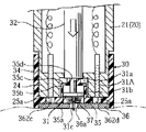
図2ないし図5に装着体30の一例の詳細を示す。この装着体30は、円筒部34と、この円筒部34の先端を塞ぐように位置する底壁部35とを備える大略キャップ状をしており、その主要部分は樹脂成形によって作製される。円筒部34の内径は、本体20の前部筒状部24の外径と対応させられており、この前部筒状部24に被せるようにして簡便に装着することができる。
2 to 5 show details of an example of the wearing
装着体30の底壁部35にはまた、上記穿刺体31が収容された陥没部35Aを覆うようにして、板状バイオセンサ36が貼着される。このバイオセンサ36は、図6ないし図8に示したように穿刺体31の穿刺針31cが通過しうる貫通孔36aと、この貫通孔36aと連通して厚みのなかを底壁部35と平行に延びる体液通路36bを備え、この体液通路36bの内壁に反応部36kが形成された構成を備えている。
A plate-
図9に示すように、たとえば0.2mmの厚みをもつ樹脂製絶縁シートからなる平面視長矩形状のベース板36Aが準備される。このベース板36Aにおいて電極が形成される面とは相対する平行面、すなわち皮膚当接面部分を図10に示す。図10に示すように、少なくとも貫通孔36aのごく近傍周辺部をあらかじめ疎水化処理を行って疎水部363aを形成してある。ここで言う、疎水化処理とは、水とのなじみを悪化させることである。ここで、疎水化処理するための化合物としては、樹脂製絶縁シートの表面を疎水化または撥水化できるものであれば特に限定されないが、例えばポリウレタン系樹脂、ポリアクリル系樹脂、ポリエステル系樹脂、ポリアミド系樹脂、ポリ塩化ビニル系樹脂、ポリスチレン系樹脂、フッ素系樹脂、その他ゴム変性物などが挙げられ、特に水溶性の樹脂とか吸湿性の高い樹脂でない限り、従来、インキのバインダーなどに使用されている公知の樹脂はいずれも使用することができる。また疎水化処理の方式としては、例えば上記樹脂を主成分とする液を所定の部分に浸透させた後乾燥させることによる印刷方式や撥水剤のコーティングなど公知の技術はいすれも使用することができる。このベース板36Aには、あらかじめたとえば1.5mm径の貫通孔36aが形成されている。このベース板36Aの上面には、グラファイトインクを用いたスクリーン印刷の手法により、作用極36cと対極36dとが膜状に形成される。作用極36cは、端子部となるべき端部領域36f(作用極36cに斜線のみを施した領域)から細状の突出部36gが延出形成された平面形態をもち、一方、対極36dは、端子部となるべき端部領域36h(対極36dに斜線のみを施した領域)から上記作用極36c側の突出部36gを両側から挟むように二股状に延びる突出部36i,36iをもつ平面形態をもっている。貫通孔36aは、対極36dの一方の突出部36iと近接して位置している。
As shown in FIG. 9, for example, a
次に、図9に示したように各スペーサ板36B,36Bに重ねるようにして、上記ベース板36Aの貫通孔36aと対応する貫通孔362bを有する平面視矩形状のカバー板36Cを重ね合わせてこのバイオセンサ36が完成する。すなわち、図6ないし図8に表れているように、上記ベース板36Aとスペーサ板36B,36Bとで形成された凹溝36eをカバー板36Cで塞ぐことによって縦方向に延びる断面横長矩形状の体液通路36bが形成され、かつ、この体液通路36bの内面に、作用極36cおよび対極36dに接触する試薬層36k(反応部)が形成され、かつ、この体液通路36bはこの板状バイオセンサ36の貫通穴36aに連通させられることとなる。また、体液通路36bにおける貫通孔36aの位置と反対側は、開放させられており、後述するように貫通孔36aを介してこの体液通路36bないし反応部36kに毛管現象によって体液(血液)が導入されるのを促す。
Next, as shown in FIG. 9, the cover plate 36C having a rectangular shape in a plan view having the through
上記のように形成された板状バイオセンサ36は、図2に良く表れているように装着体30の底壁部35に、穿刺針31cの位置とバイオセンサ36の貫通孔36aの位置とが一致するようにして貼着される。なお、図4および図5に表れているように、装着体30の底壁部35には、バイオセンサ36のベース板36Aの両端部に露出する作用極36cおよび対極36d用の端子部36f,36hと対応する丸穴362c,362dが形成されている。この丸穴362c,362dは、装着体30を本体20に装着したときに、本体20側のコネクタピン25a,25aの先端を上記端子部36f,36hに接触させるためのものである。装着体30の底壁部35にはまた、バイオセンサ貼着領域を挟むようにして弓形の開口36m,36mが形成されている。
In the plate-
【0029】
【実施例2】
実施例1と同様の体液測定装置において、板状バイオセンサ36の作製工程における絶縁ベース板36Aの部分を以下に説明するように変更する。
[0029]
[Example 2]
In the same body fluid measuring device as in Example 1, the portion of the
【0033】
【実施例3】
実施例1と同様の体液測定装置において、板状バイオセンサ36の作製工程における絶縁ベース板36Aの部分を以下に説明するように変更する。
0033
[Example 3]
In the same body fluid measuring device as in Example 1, the portion of the
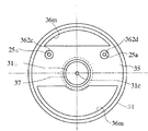
図9に示すように、たとえば0.2mmの厚みをもつ樹脂製絶縁シートからなる平面視長矩形状のベース板36Aが準備される。このベース板36Aには、あらかじめたとえば1.5mm径の貫通孔361aが形成されている。このベース板36Aにおいて電極が形成される面とは相対する平行面、すなわち皮膚当接面35aから見たベース板36Aの斜視図を図10に示す。図10に示すように、皮膚当接面35aには、貫通孔361aのごく近傍周辺部に、立体遮蔽物363aを配してある。ここでいう立体遮蔽物363aとは、例えばOリングなどで、傷から流出した血液の拡散を遮断することを目的としている。
As shown in FIG. 9, for example, a
【0037】
【発明の効果】
このように本発明によれば、上記体液測定装置10を用いて、装着体30の端面およびバイオセンサ36の皮膚当接面35aを患者の指先や耳たぶ等に押し当てた状態を保持しつつ、穿刺針31cを突出させるという操作をおこなうと、体液が皮膚とバイオセンサ36の隙間に入り込むことなく、血糖値等の体液測定を適切に行うことができる。
0037
【Effect of the invention】
As described above, according to the present invention, the body fluid measuring device 10 is used to maintain the state in which the end surface of the wearing
【図面の簡単な説明】
【図1】
本願発明に係る体液測定装置の全体外観図である。
【図2】
穿刺体が退避した状態における装着体の詳細を示す拡大縦断面図であり、図4のII−II線に沿う断面に相当する図である。
【図3】
穿刺体が進出した状態における装着体の詳細を示す拡大縦断面図である。
【図4】
装着体の底面図である。
【図5】
バイオセンサを外した状態での装着体の底面図である。
【図6】
バイオセンサの平面図である。
【図7】
図6のVII
−VII 線に沿う断面図である。
【図8】
図7における一点鎖線で囲まれた領域の拡大図である。
【図9】
バイオセンサの分解斜視図である。
【図10】
バイオセンサを皮膚当接面側から見た斜視図である。
【符号の説明】
10 体液測定装置
20 本体
23 押圧部(駆動機構を構成する)
25a コネクタピン(本体の端子としての)
30 装着体
31 穿刺体
32 押圧ロッド(駆動機構を構成する)
35a 皮膚当接面
36 バイオセンサ
36a 貫通孔(バイオセンサの)
36f,36h 端子部(センサの電極としての)
361a 貫通孔(皮膚当接面の)
363a 疎水部
[Simple explanation of drawings]
FIG. 1
It is an overall external view of the body fluid measuring apparatus which concerns on this invention.
FIG. 2
It is an enlarged vertical cross-sectional view which shows the detail of the wearing body in the state where the puncture body is retracted, and is the figure corresponding to the cross section along the line II-II of FIG.
FIG. 3
It is an enlarged vertical sectional view which shows the detail of the wearing body in the state where the puncture body is advanced.
FIG. 4
It is a bottom view of the wearing body.
FIG. 5
It is the bottom view of the wearing body with the biosensor removed.
FIG. 6
It is a top view of a biosensor.
FIG. 7
VII in Figure 6
It is a cross-sectional view along the −VII line.
FIG. 8
It is an enlarged view of the region surrounded by the alternate long and short dash line in FIG. 7.
FIG. 9
It is an exploded perspective view of a biosensor.
FIG. 10
It is a perspective view which looked at the biosensor from the skin contact surface side.
[Explanation of symbols]
10 Body
25a connector pin (as a terminal on the main unit)
30 Mounting
35a
36f, 36h terminal (as sensor electrode)
361a Through hole (on the skin contact surface)
363a Hydrophobic part
Priority Applications (1)
| Application Number | Priority Date | Filing Date | Title |
|---|---|---|---|
| JP31402998A JP4166878B2 (en) | 1998-10-15 | 1998-10-15 | Biosensor used in lancet-integrated body fluid measuring device |
Applications Claiming Priority (1)
| Application Number | Priority Date | Filing Date | Title |
|---|---|---|---|
| JP31402998A JP4166878B2 (en) | 1998-10-15 | 1998-10-15 | Biosensor used in lancet-integrated body fluid measuring device |
Publications (3)
| Publication Number | Publication Date |
|---|---|
| JP2000116628A JP2000116628A (en) | 2000-04-25 |
| JP2000116628A5 true JP2000116628A5 (en) | 2005-12-02 |
| JP4166878B2 JP4166878B2 (en) | 2008-10-15 |
Family
ID=18048365
Family Applications (1)
| Application Number | Title | Priority Date | Filing Date |
|---|---|---|---|
| JP31402998A Expired - Fee Related JP4166878B2 (en) | 1998-10-15 | 1998-10-15 | Biosensor used in lancet-integrated body fluid measuring device |
Country Status (1)
| Country | Link |
|---|---|
| JP (1) | JP4166878B2 (en) |
Cited By (16)
| Publication number | Priority date | Publication date | Assignee | Title |
|---|---|---|---|---|
| US7766829B2 (en) | 2005-11-04 | 2010-08-03 | Abbott Diabetes Care Inc. | Method and system for providing basal profile modification in analyte monitoring and management systems |
| US7811231B2 (en) | 2002-12-31 | 2010-10-12 | Abbott Diabetes Care Inc. | Continuous glucose monitoring system and methods of use |
| US8123686B2 (en) | 2007-03-01 | 2012-02-28 | Abbott Diabetes Care Inc. | Method and apparatus for providing rolling data in communication systems |
| US8226558B2 (en) | 1998-04-30 | 2012-07-24 | Abbott Diabetes Care Inc. | Analyte monitoring device and methods of use |
| US8226891B2 (en) | 2006-03-31 | 2012-07-24 | Abbott Diabetes Care Inc. | Analyte monitoring devices and methods therefor |
| US8287454B2 (en) | 1998-04-30 | 2012-10-16 | Abbott Diabetes Care Inc. | Analyte monitoring device and methods of use |
| US8437966B2 (en) | 2003-04-04 | 2013-05-07 | Abbott Diabetes Care Inc. | Method and system for transferring analyte test data |
| US8465425B2 (en) | 1998-04-30 | 2013-06-18 | Abbott Diabetes Care Inc. | Analyte monitoring device and methods of use |
| US8512239B2 (en) | 2003-06-10 | 2013-08-20 | Abbott Diabetes Care Inc. | Glucose measuring device for use in personal area network |
| US8593109B2 (en) | 2006-03-31 | 2013-11-26 | Abbott Diabetes Care Inc. | Method and system for powering an electronic device |
| US8612159B2 (en) | 1998-04-30 | 2013-12-17 | Abbott Diabetes Care Inc. | Analyte monitoring device and methods of use |
| US8652043B2 (en) | 2001-01-02 | 2014-02-18 | Abbott Diabetes Care Inc. | Analyte monitoring device and methods of use |
| US8688188B2 (en) | 1998-04-30 | 2014-04-01 | Abbott Diabetes Care Inc. | Analyte monitoring device and methods of use |
| US8771183B2 (en) | 2004-02-17 | 2014-07-08 | Abbott Diabetes Care Inc. | Method and system for providing data communication in continuous glucose monitoring and management system |
| US8920319B2 (en) | 2005-11-01 | 2014-12-30 | Abbott Diabetes Care Inc. | Analyte monitoring device and methods of use |
| US8974386B2 (en) | 1998-04-30 | 2015-03-10 | Abbott Diabetes Care Inc. | Analyte monitoring device and methods of use |
Families Citing this family (9)
| Publication number | Priority date | Publication date | Assignee | Title |
|---|---|---|---|---|
| US9066695B2 (en) | 1998-04-30 | 2015-06-30 | Abbott Diabetes Care Inc. | Analyte monitoring device and methods of use |
| WO2002100272A1 (en) * | 2001-06-11 | 2002-12-19 | Arkray, Inc. | Puncturing element integration mounting body, and method of producing the same |
| EP1404232B1 (en) * | 2001-06-12 | 2009-12-02 | Pelikan Technologies Inc. | Blood sampling apparatus and method |
| JPWO2003042679A1 (en) * | 2001-11-14 | 2005-03-10 | 松下電器産業株式会社 | Biosensor |
| EP1854410A4 (en) * | 2005-03-02 | 2009-12-02 | Nat Inst Of Advanced Ind Scien | Biosensor coupled with needle |
| JP4576624B2 (en) * | 2005-03-02 | 2010-11-10 | 独立行政法人産業技術総合研究所 | Needle integrated biosensor |
| WO2007077930A1 (en) * | 2006-01-05 | 2007-07-12 | Matsushita Electric Industrial Co., Ltd. | Blood test apparatus |
| JP2007282864A (en) * | 2006-04-17 | 2007-11-01 | Sumitomo Electric Ind Ltd | Biosensor system |
| JP5043863B2 (en) * | 2006-12-21 | 2012-10-10 | パナソニック株式会社 | Blood test equipment |
-
1998
- 1998-10-15 JP JP31402998A patent/JP4166878B2/en not_active Expired - Fee Related
Cited By (40)
| Publication number | Priority date | Publication date | Assignee | Title |
|---|---|---|---|---|
| US8617071B2 (en) | 1998-04-30 | 2013-12-31 | Abbott Diabetes Care Inc. | Analyte monitoring device and methods of use |
| US8880137B2 (en) | 1998-04-30 | 2014-11-04 | Abbott Diabetes Care Inc. | Analyte monitoring device and methods of use |
| US9072477B2 (en) | 1998-04-30 | 2015-07-07 | Abbott Diabetes Care Inc. | Analyte monitoring device and methods of use |
| US8597189B2 (en) | 1998-04-30 | 2013-12-03 | Abbott Diabetes Care Inc. | Analyte monitoring device and methods of use |
| US8226558B2 (en) | 1998-04-30 | 2012-07-24 | Abbott Diabetes Care Inc. | Analyte monitoring device and methods of use |
| US8226557B2 (en) | 1998-04-30 | 2012-07-24 | Abbott Diabetes Care Inc. | Analyte monitoring device and methods of use |
| US8974386B2 (en) | 1998-04-30 | 2015-03-10 | Abbott Diabetes Care Inc. | Analyte monitoring device and methods of use |
| US8235896B2 (en) | 1998-04-30 | 2012-08-07 | Abbott Diabetes Care Inc. | Analyte monitoring device and methods of use |
| US8287454B2 (en) | 1998-04-30 | 2012-10-16 | Abbott Diabetes Care Inc. | Analyte monitoring device and methods of use |
| US8612159B2 (en) | 1998-04-30 | 2013-12-17 | Abbott Diabetes Care Inc. | Analyte monitoring device and methods of use |
| US8465425B2 (en) | 1998-04-30 | 2013-06-18 | Abbott Diabetes Care Inc. | Analyte monitoring device and methods of use |
| US8622906B2 (en) | 1998-04-30 | 2014-01-07 | Abbott Diabetes Care Inc. | Analyte monitoring device and methods of use |
| US8480580B2 (en) | 1998-04-30 | 2013-07-09 | Abbott Diabetes Care Inc. | Analyte monitoring device and methods of use |
| US8688188B2 (en) | 1998-04-30 | 2014-04-01 | Abbott Diabetes Care Inc. | Analyte monitoring device and methods of use |
| US8641619B2 (en) | 1998-04-30 | 2014-02-04 | Abbott Diabetes Care Inc. | Analyte monitoring device and methods of use |
| US8660627B2 (en) | 1998-04-30 | 2014-02-25 | Abbott Diabetes Care Inc. | Analyte monitoring device and methods of use |
| US8668645B2 (en) | 2001-01-02 | 2014-03-11 | Abbott Diabetes Care Inc. | Analyte monitoring device and methods of use |
| US8652043B2 (en) | 2001-01-02 | 2014-02-18 | Abbott Diabetes Care Inc. | Analyte monitoring device and methods of use |
| US7811231B2 (en) | 2002-12-31 | 2010-10-12 | Abbott Diabetes Care Inc. | Continuous glucose monitoring system and methods of use |
| US8622903B2 (en) | 2002-12-31 | 2014-01-07 | Abbott Diabetes Care Inc. | Continuous glucose monitoring system and methods of use |
| US8187183B2 (en) | 2002-12-31 | 2012-05-29 | Abbott Diabetes Care Inc. | Continuous glucose monitoring system and methods of use |
| US8682598B2 (en) | 2003-04-04 | 2014-03-25 | Abbott Laboratories | Method and system for transferring analyte test data |
| US8560250B2 (en) | 2003-04-04 | 2013-10-15 | Abbott Laboratories | Method and system for transferring analyte test data |
| US8437966B2 (en) | 2003-04-04 | 2013-05-07 | Abbott Diabetes Care Inc. | Method and system for transferring analyte test data |
| US8483974B2 (en) | 2003-04-04 | 2013-07-09 | Abbott Diabetes Care Inc. | Method and system for transferring analyte test data |
| US8647269B2 (en) | 2003-06-10 | 2014-02-11 | Abbott Diabetes Care Inc. | Glucose measuring device for use in personal area network |
| US8512239B2 (en) | 2003-06-10 | 2013-08-20 | Abbott Diabetes Care Inc. | Glucose measuring device for use in personal area network |
| US8771183B2 (en) | 2004-02-17 | 2014-07-08 | Abbott Diabetes Care Inc. | Method and system for providing data communication in continuous glucose monitoring and management system |
| US8915850B2 (en) | 2005-11-01 | 2014-12-23 | Abbott Diabetes Care Inc. | Analyte monitoring device and methods of use |
| US8920319B2 (en) | 2005-11-01 | 2014-12-30 | Abbott Diabetes Care Inc. | Analyte monitoring device and methods of use |
| US9326716B2 (en) | 2005-11-01 | 2016-05-03 | Abbott Diabetes Care Inc. | Analyte monitoring device and methods of use |
| US8585591B2 (en) | 2005-11-04 | 2013-11-19 | Abbott Diabetes Care Inc. | Method and system for providing basal profile modification in analyte monitoring and management systems |
| US7766829B2 (en) | 2005-11-04 | 2010-08-03 | Abbott Diabetes Care Inc. | Method and system for providing basal profile modification in analyte monitoring and management systems |
| US8593109B2 (en) | 2006-03-31 | 2013-11-26 | Abbott Diabetes Care Inc. | Method and system for powering an electronic device |
| US8933664B2 (en) | 2006-03-31 | 2015-01-13 | Abbott Diabetes Care Inc. | Method and system for powering an electronic device |
| US8226891B2 (en) | 2006-03-31 | 2012-07-24 | Abbott Diabetes Care Inc. | Analyte monitoring devices and methods therefor |
| US8597575B2 (en) | 2006-03-31 | 2013-12-03 | Abbott Diabetes Care Inc. | Analyte monitoring devices and methods therefor |
| US9380971B2 (en) | 2006-03-31 | 2016-07-05 | Abbott Diabetes Care Inc. | Method and system for powering an electronic device |
| US8123686B2 (en) | 2007-03-01 | 2012-02-28 | Abbott Diabetes Care Inc. | Method and apparatus for providing rolling data in communication systems |
| US9095290B2 (en) | 2007-03-01 | 2015-08-04 | Abbott Diabetes Care Inc. | Method and apparatus for providing rolling data in communication systems |
Similar Documents
| Publication | Publication Date | Title |
|---|---|---|
| JP2000116628A5 (en) | ||
| JP4166878B2 (en) | Biosensor used in lancet-integrated body fluid measuring device | |
| JP3873093B2 (en) | Lancet-integrated body fluid measuring device and attached body to be used by attaching to this body fluid measuring device | |
| JP3691457B2 (en) | Electrochemical sensor and manufacturing method thereof | |
| JP2000000231A5 (en) | ||
| EP1262768A1 (en) | Analytical element, and measuring instrument and substrate determining method using the same | |
| JP2011025091A (en) | Piercing element integrally installed body for concentration measuring device with analyzing apparatus, and body fluid sampling apparatus | |
| EP1903334A1 (en) | Biosensor | |
| US20070266871A1 (en) | Diagnostic test media and methods for the manufacture thereof | |
| KR101522322B1 (en) | Electrochemical Test Strips | |
| US10746724B2 (en) | Sensor array | |
| CN108348199B (en) | Sensor for detecting an analyte in a body fluid and sensor assembly | |
| US20040000371A1 (en) | Embedded metallic deposits | |
| CN214539367U (en) | Biosensor and method for measuring the same | |
| KR101355337B1 (en) | Electrochemical sensor, lancet, and bodily fluid measuring apparatus | |
| JP2000116626A5 (en) | ||
| JP4893921B2 (en) | Biosensor | |
| JP4933656B1 (en) | Electrode device for electrochemical measuring chip | |
| JP4635140B2 (en) | Lancet-integrated body fluid measuring device and attached body to be used by attaching to this body fluid measuring device | |
| JPH11248667A (en) | Bio-sensor | |
| TWI332575B (en) | ||
| CN100432660C (en) | Structure of electrochemical sensing test block and producing method thereof | |
| DE20012374U1 (en) | Spectroelectrochemical measuring cell | |
| CA2971472C (en) | Sensor array with anti-diffusion region(s) to extend shelf life | |
| JP4635260B2 (en) | Biosensor and manufacturing method thereof |