JP4635260B2 - Biosensor and manufacturing method thereof - Google Patents
Biosensor and manufacturing method thereof Download PDFInfo
- Publication number
- JP4635260B2 JP4635260B2 JP2006072444A JP2006072444A JP4635260B2 JP 4635260 B2 JP4635260 B2 JP 4635260B2 JP 2006072444 A JP2006072444 A JP 2006072444A JP 2006072444 A JP2006072444 A JP 2006072444A JP 4635260 B2 JP4635260 B2 JP 4635260B2
- Authority
- JP
- Japan
- Prior art keywords
- biosensor
- cover
- electrically insulating
- insulating substrate
- soft
- Prior art date
- Legal status (The legal status is an assumption and is not a legal conclusion. Google has not performed a legal analysis and makes no representation as to the accuracy of the status listed.)
- Expired - Fee Related
Links
Images
Landscapes
- Measurement Of The Respiration, Hearing Ability, Form, And Blood Characteristics Of Living Organisms (AREA)
Description
本発明は、バイオセンサーおよびその製造法に関する。さらに詳しくは、一枚の電気絶縁性材料から形成されるバイオセンサーおよびその製造法に関する。 The present invention relates to a biosensor and a method for producing the same. More specifically, the present invention relates to a biosensor formed from a single electrically insulating material and a method for manufacturing the same.
従来、使い捨て型のセンサー(特許文献1および特許文献3)としては定量性を確保するために立体構造をとり、さらに毛細管現象(特許文献5および特許文献6)などを利用して試料液が自動的にセンサーの内部に導入する仕組みが知られている(特許文献7)。このような構成のセンサーは、電気絶縁性の基板上に、スペーサー、さらにカバーを積層して組み立てられる。基板上には電極パターン、カバー上には毛細管現象に必要な空気が抜けるために必要な空気孔が開けられている。これらの構成部品は各々所定の形状に予め打ち抜いておく必要があり、また立体加工における各部品の正確な重ねあわせのための位置決めも必要となるため、構成部品の数が増えるに従って立体加工の工程が複雑になる。さらに、これらのセンサーに分子識別素子やメデイエーターなどの試薬の塗布(特許文献2および特許文献4)や妨害物質の影響から回避するための膜(特許文献8)の形成などを必要とする場合は、さらに複雑な工程となるといった問題がある。
上述した従来のセンサーは製造に多くの工程、材料を要し、複雑な構造をとらざるを得なかった。その結果として、製造ラインに多大な設備投資を必要とし、また製品の歩留まりも充分ではなく、コスト的に負担が大きかった。当然、材料調達時、製造時の環境負荷も大きいものであった。さらに特性上では複雑な工程、特に基板積層時の位置合わせなどのため、製造されたセンサー特性のばらつきの指標である変動係数(CV)も充分ではなかった。また、バイオセンサーの形状変化は測定の精度や再現性の低下を招くため、該バイオセンサーにおいて、製造後、カバー等の反り返りなどが発生しない、長期形状安定性を確保することが求められていた。 The conventional sensor described above requires many processes and materials for manufacturing, and has to take a complicated structure. As a result, a large capital investment was required for the production line, the product yield was not sufficient, and the cost was high. Naturally, the environmental load at the time of material procurement and manufacturing was also large. Furthermore, due to complicated processes, especially alignment during substrate lamination, the coefficient of variation (CV), which is an indicator of variations in sensor characteristics produced, was not sufficient. In addition, since the change in shape of the biosensor causes a decrease in measurement accuracy and reproducibility, it has been required to ensure long-term shape stability in the biosensor without causing warping of a cover or the like after manufacturing. .
上記課題を解決するために、発明者らは先に一枚の電気絶縁性平面硬質基板を折り加工または曲げ加工または折り曲げ加工することにより製造されるバイオセンサーを提案している。このバイオセンサーは一枚の電気絶縁性基板上に電極を形成させ、電極が基板の内側に配置されるように一枚の平面基板を立体的に加工することで電極配置を平面または立体的として、狭小な部位での定量的な測定を可能にするものであり、一枚の平面基板からセンサーの主要構造を構成することに特徴がある。しかるにかかる方法では、折畳み部分の反り返りを防ぐため、折畳み部分へのミシン目の作製、該折畳み部分への固定具の装着や、熱圧着、切断などが必要であった。
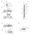
図16を用いて、上記バイオセンサーの問題点について詳しく説明する。a)およびb)は軟質シート1の形状が異なるのみであり、いずれも従来のバイオセンサーの一組立例を示している。i)には、表面に導電体7,7が形成され、折畳み部分となるミシン目16が設けられた一枚の軟質シート1およびこれに被覆されるレジスト6が示されている。レジスト6は、スペーサー2としても働く。ii)には、表面上にレジスト層が形成された硬質の電気絶縁性基板4および次の組立工程で被覆される接着剤層5が示されている。ここで、接着剤層5はレジスト6と同様にスペーサー2としても働く。iii)では、表面に接着剤層5が形成された基板がミシン目16に沿って折畳まれ、重なる前の状態を示している。iv)では、硬質な電気絶縁性基板4によって形成された折畳み成形体14であるバイオセンサー3を示している。この場合、ミシン目を形成する工程が必要となるうえ、ミシン目16に沿って形成された折畳み部分がレジスト層6や接着剤層5などのスペーサーの厚みによって反り返ることがあるため、この部分に固定具を装着したり、熱圧着により反り返りストレスを除くなどの何らかの処置が必要であった。
The problem of the biosensor will be described in detail with reference to FIG. a) and b) differ only in the shape of the
以上述べた如く、かかる折畳み式センサーでは製造工程の大幅な簡略化、材料の削減、極めて単純な構造などにより、従来のセンサーの製造法を大いに改善することに成功しているものの、該製造法により形成されたセンサーは、折畳み部分の反り返りを防ぐため、ミシン目の形成、該折畳み部分への固定具の装着や、熱圧着、切断などが必要であった。 As described above, such a foldable sensor has succeeded in greatly improving the manufacturing method of the conventional sensor by greatly simplifying the manufacturing process, reducing the material, and extremely simple structure. In order to prevent the folded portion from being warped, the sensor formed by the above method requires formation of perforations, attachment of a fixing tool to the folded portion, thermocompression bonding, cutting, and the like.
本発明の目的は、従来のセンサーのように製造に多くの工程、材料を要することなく製造が可能なバイオセンサーであって、かつ製造されたバイオセンサーが形状変化を起こさず、さらには試料体積を正確に規定し得るバイオセンサーおよびその製造法を提供することにある。 An object of the present invention is a biosensor that can be manufactured without requiring many processes and materials as in the case of a conventional sensor, and the manufactured biosensor does not cause a shape change, and further, a sample volume. It is an object of the present invention to provide a biosensor and a method for producing the same.
かかる本発明の目的は、電気絶縁性基板上に電極、スペーサーおよびカバーが順次形成されたバイオセンサーにおいて、電気絶縁性基板部分およびカバー部分が、1枚の軟質シートを、基板形成部およびカバー形成部の間を繋ぐ軟質部を残したうえで、該軟質部以外の基板形成部分およびカバー形成部分について硬化させることにより形成されることを特徴とするバイオセンサーによって達成され、かかるバイオセンサーは、軟質シートの電気絶縁性基板部分およびカバー部分を硬化させた後、電極およびスペーサーを形成し、電極をバイオセンサー内部に収めるように、電気絶縁性基板およびカバーを繋ぐ軟質部で電気絶縁性基板およびカバーを折畳むことにより製造される。 An object of the present invention is to provide a biosensor in which electrodes, spacers, and a cover are sequentially formed on an electrically insulating substrate, wherein the electrically insulating substrate portion and the cover portion form one flexible sheet, and the substrate forming portion and the cover formation. upon leaving the soft portion connecting the parts is achieved by biosensor characterized in that it is formed by curing the substrate forming portion and the cover forming a portion other than the soft quality unit, such biosensors, soft After the electrically insulating substrate portion and the cover portion of the sheet are cured, an electrode and a spacer are formed, and the electrically insulating substrate and cover are formed by a soft portion connecting the electrically insulating substrate and the cover so that the electrode is accommodated inside the biosensor. It is manufactured by folding.
本発明に係るバイオセンサーは、電気絶縁性基板およびカバー間に軟質部を設けることにより、該部分で折りたたむことで折畳み部分の反り返りが発生せず、これを防ぐための折畳み部分への固定具の装着や、熱圧着、切断などが必要ないといったすぐれた効果を奏する。 In the biosensor according to the present invention, by providing a soft portion between the electrically insulating substrate and the cover, folding of the folded portion does not occur when the folded portion is folded, and the fixture to the folded portion to prevent this is prevented. Excellent effects such as no need for mounting, thermocompression bonding and cutting.
さらに、本発明に係る針一体型バイオセンサーは、折畳み構造のバイオセンサー内に穿刺針を内包固定した場合に、穿刺採血時に絶縁性基板およびカバー間に設けられた軟質部分を穿刺針が突き破り、穿刺後、軟質シート材料の復元力によって穿刺針が元の位置に戻り、その際に新たに形成された試料導入口から採血が導入されることで、血液成分を電気化学的に測定することができる。 Furthermore, the needle-integrated biosensor according to the present invention has a puncture needle that breaks through a soft portion provided between the insulating substrate and the cover when blood is collected from the puncture when the puncture needle is contained and fixed in the biosensor having a folding structure. After the puncture, the puncture needle returns to the original position by the restoring force of the soft sheet material, and blood is introduced from the newly formed sample introduction port at that time, so that blood components can be measured electrochemically. it can.
電気絶縁性基板およびカバーは、1枚の軟質シートから形成される。軟質シート材料としては、光または熱などにより硬化する電気絶縁性シート材料、例えばビニルエステル、ポリイミドまたはポリエチレンなどが挙げられ、電気絶縁性基板およびカバーは、電気絶縁性基板およびカバー間に軟質部を残した状態で、該軟質部分以外の基板形成部分およびカバー形成部分を光または熱によって硬化させることにより形成される。軟質部には、測定対象試料液を導入するための試料導入口を設けることもできる。 The electrically insulating substrate and the cover are formed from a single flexible sheet. Examples of the soft sheet material include an electrically insulating sheet material that is cured by light or heat, such as vinyl ester, polyimide, or polyethylene. The electrically insulating substrate and the cover include a soft part between the electrically insulating substrate and the cover. In the remaining state, the substrate forming portion and the cover forming portion other than the soft portion are cured by light or heat. The soft part can also be provided with a sample inlet for introducing the sample liquid to be measured.
電気絶縁性基板上には、電極が形成される。電極は、スクリーン印刷法、蒸着法、スパッタリング法、箔貼り付け法、メッキ法など公知の方法により形成され、その材料としては、カーボン、銀、銀/塩化銀、白金、金、ニッケル、銅、パラジウム、チタン、イリジウム、鉛、酸化錫、白金黒などが挙げられる。ここで、カーボンとしては、カーボンナノチューブ、カーボンマイクロコイル、カーボンナノホーン、フラーレン、デンドリマーもしくはそれらの誘導体を用いることができる。 An electrode is formed on the electrically insulating substrate. The electrode is formed by a known method such as a screen printing method, a vapor deposition method, a sputtering method, a foil bonding method, a plating method, and the materials thereof are carbon, silver, silver / silver chloride, platinum, gold, nickel, copper, Examples include palladium, titanium, iridium, lead, tin oxide, and platinum black. Here, as the carbon, carbon nanotubes, carbon microcoils, carbon nanohorns, fullerenes, dendrimers, or derivatives thereof can be used.
電極は、作用極と対極で形成される2極法または作用極と対極、参照極で形成される3極法、あるいはそれ以上の極数の電極法であってもよい。ここで、3極法を採用すると、測定対象物質の電気化学測定の他に、搬送路内に導入される採血の移動速度の計測ができ、これによりヘマトクリット値が測定できる。また、2組以上の電極系で構成されていても良い。これらの電極は、電気絶縁性基板上にまとめて形成することもできるし、電気絶縁性基板およびカバーの各々に形成することもできる。電気絶縁性基板およびカバーの各々に電極を形成した場合には、試料体積の少量化を図ることができる。 The electrode may be a two-pole method formed with a working electrode and a counter electrode or a three-pole method formed with a working electrode and a counter electrode, a reference electrode, or an electrode method with more poles. Here, when the tripolar method is adopted, in addition to the electrochemical measurement of the measurement target substance, it is possible to measure the moving speed of the blood sample introduced into the transport path, thereby measuring the hematocrit value. Moreover, you may be comprised by 2 or more sets of electrode systems. These electrodes can be formed together on the electrically insulating substrate, or can be formed on each of the electrically insulating substrate and the cover. When electrodes are formed on each of the electrically insulating substrate and the cover, the sample volume can be reduced.
電極が形成された基板上には、試薬層(電極反応部)を形成することができる。試薬層はスクリーン印刷法またはデスペンサー法により形成され、この試薬層の電極表面または基板表面への固定化は、乾燥を伴う吸着法または共有結合法により行うことができる。バイオセンサーの電極反応部に配置する試薬としては、例えば血糖値測定用に構成する場合、酸化酵素であるグルコースオキシターゼおよびメディエーターとしてのフェリシアン化カリウムを含むものが挙げられる。試薬が血液によって溶解されると、酵素反応が開始される結果、反応層に共存させているフェリシアン化カリウムが還元され、還元型の電子伝達体であるフェロシアン化カリウムが蓄積される。その量は、基質濃度、すなわち血液中のグルコース濃度に比例する。一定時間蓄積された還元型の電子伝達体は、電気化学反応により酸化される。後述する測定装置本体内の電子回路は、このとき測定される陽極電流から、グルコース濃度(血糖値)を演算・決定し、本体表面に配置された表示部に表示する。 A reagent layer (electrode reaction part) can be formed on the substrate on which the electrode is formed. The reagent layer is formed by a screen printing method or a dispenser method, and the reagent layer can be immobilized on the electrode surface or the substrate surface by an adsorption method involving drying or a covalent bonding method. Examples of the reagent arranged in the electrode reaction part of the biosensor include those containing glucose oxidase as an oxidase and potassium ferricyanide as a mediator when configured for blood glucose measurement. When the reagent is dissolved by the blood, the enzyme reaction is started. As a result, potassium ferricyanide coexisting in the reaction layer is reduced and potassium ferrocyanide, which is a reduced electron carrier, is accumulated. The amount is proportional to the substrate concentration, ie the glucose concentration in the blood. The reduced electron carrier accumulated for a certain time is oxidized by an electrochemical reaction. An electronic circuit in the main body of the measuring apparatus, which will be described later, calculates and determines the glucose concentration (blood glucose level) from the anode current measured at this time, and displays it on the display unit arranged on the main body surface.
また、採血口の周辺および電極あるいは試薬層(電極反応部)表面に界面活性剤、脂質を塗布することができる。界面活性剤や脂質の塗布により、試料の移動を円滑にさせることが可能となる。 In addition, a surfactant and lipid can be applied around the blood collection port and on the surface of the electrode or reagent layer (electrode reaction part). By applying a surfactant or lipid, the sample can be moved smoothly.
以上の採血が満たされる電極上に試薬層が設けられたバイオセンサーは、採血口から送り込まれる採血が電極上の試薬層と接触することにより、採血と試薬とが反応する。この反応は、電極における電気的な変化としてモニタリングされる。 In the biosensor in which the reagent layer is provided on the electrode filled with the above blood collection, the blood collection and the reagent react when the blood collected from the blood collection port contacts the reagent layer on the electrode. This reaction is monitored as an electrical change at the electrode.
(試薬層形成)電極は、レジスト層によりその面積を規定することができる。レジスト層は、基板と反応あるいは溶解せず、折畳み時に折畳み部分の反り返りが発生しない程度の軟質な材料からなるもの、例えば紫外線または可視光線硬化型のビニル・アクリル系樹脂、ウレタンアクリレート系樹脂、ポリエステルアクリレート系樹脂、ポリ塩化ビニル、ポリエチレン、ポリエステル、ポリオレフィン、ポリフッ化ビニルなどからなり、その厚みが約5〜500μm、好ましくは約10〜100μmのものが用いられ、スクリーン印刷法などにより形成される。レジストの使用の目的は電極パターンを明確にし、電極面積を規定する以外にも、試薬層が存在しない試料搬送路を絶縁するなどの目的がある。またレジスト層は、後述する穿刺針が設けられた針一体型バイオセンサーにおいて、電極反応層に配置された試薬層との接触を防ぐためにも用いることができる。 (Reagent layer formation) The area of the electrode can be defined by the resist layer. The resist layer is made of a soft material that does not react or dissolve with the substrate and does not cause bending of the folded portion when folded, such as ultraviolet or visible light curable vinyl / acrylic resin, urethane acrylate resin, polyester. It is made of acrylate resin, polyvinyl chloride, polyethylene, polyester, polyolefin, polyvinyl fluoride, etc., and has a thickness of about 5 to 500 μm, preferably about 10 to 100 μm, and is formed by a screen printing method or the like. The purpose of using the resist is to clarify the electrode pattern and define the electrode area, and to insulate the sample transport path where no reagent layer is present. The resist layer can also be used to prevent contact with the reagent layer disposed in the electrode reaction layer in a needle-integrated biosensor provided with a puncture needle described later.
基板およびカバーは、アクリル樹脂系接着剤などの接着剤を介して接着されてバイオセンサーを構成する。かかる接着剤層も、スクリーン印刷法により形成することが可能であり、約5〜500μm、好ましくは約10〜100μmの厚さで形成され、かかる接着剤層はレジスト層同様スペーサーとしても作用する。なお、接着剤層中に上記試薬を含有させることもできる。 The substrate and the cover are bonded via an adhesive such as an acrylic resin adhesive to constitute a biosensor. Such an adhesive layer can also be formed by a screen printing method, and is formed with a thickness of about 5 to 500 μm, preferably about 10 to 100 μm, and such an adhesive layer acts as a spacer as well as a resist layer. In addition, the said reagent can also be contained in an adhesive bond layer.
また、以上の構成よりなるバイオセンサーは、電気絶縁性基板およびカバー間に設けられた軟質部において、電極をバイオセンサー内部に収めるように電気絶縁性基板およびカバーを折畳むことにより形成される。このようなバイオセンサーは、基板およびカバー間に設けられた軟質部に沿って折り畳むため、折畳み部分の反り返りが発生せず、これを防ぐためのミシン目の作製、折畳み部分への固定具の装着や、熱圧着、切断などが必要ないといったすぐれた効果を奏する。 In addition, the biosensor having the above configuration is formed by folding the electrically insulating substrate and the cover so that the electrode is accommodated in the biosensor in the soft portion provided between the electrically insulating substrate and the cover. Since such a biosensor folds along the soft part provided between the substrate and the cover, the folding part does not warp, and the perforation is made to prevent this, and the fixing part is attached to the folding part. In addition, it has excellent effects such as no need for thermocompression bonding and cutting.
かかるバイオセンサーは、長大な軟質シートの軟質部形成部分以外の硬化を行った後、電極等を多数形成したうえで、基板およびカバー間に設けられた軟質部に沿って折り畳んだ後、センサー形状に打ち抜くことにより、一度に大量のバイオセンサーを製造できる。このような製造方法により作製されるバイオセンサーは、再現性も大変に良くなり、従来の積層法によっては成しえなかった特長を有している。 Such a biosensor is a sensor shape after it is cured along the soft part provided between the substrate and the cover after forming a large number of electrodes after curing other than the soft part forming part of the long soft sheet. By punching in, a large amount of biosensor can be manufactured at once. The biosensor produced by such a production method has very good reproducibility and has features that cannot be achieved by the conventional lamination method.
また、接着剤層上には被検体の皮膚から体液を採取するための穿刺針を配置することもできる。穿刺針としては、被検体を穿刺する必要があるため、これに耐え得る強度を持ち、鋭利であることが望ましく、また穿刺時の痛みを抑えるために、細い穿刺針であることが好ましい。具体的には、テルモ社製で、21〜33ゲージのものが用いられる。穿刺針は被検体の皮膚を突き破ることができれば中空針であっても棒状針でも良い。さらに、穿刺針は使用されるまでバイオセンサー内に衛生的に収納されている必要があることから、抗菌・抗ウィルスに効果がある光触媒機能を針の先端表面に付与させても良い。その場合、酸化チタンまたは二酸化チタンの膜が望ましい。 A puncture needle for collecting body fluid from the skin of the subject can also be disposed on the adhesive layer. As the puncture needle, it is necessary to puncture the subject, and it is desirable that the puncture needle is strong and sharp enough to withstand this, and a thin puncture needle is preferable in order to suppress pain during puncture. Specifically, a 21-33 gauge thing by Terumo company is used. The puncture needle may be a hollow needle or a rod-like needle as long as it can penetrate the subject's skin. Furthermore, since the puncture needle needs to be hygienicly stored in the biosensor until it is used, a photocatalytic function effective for antibacterial and antiviral effects may be imparted to the needle tip surface. In that case, a film of titanium oxide or titanium dioxide is desirable.
このような針一体型バイオセンサーは、被検体への穿刺時に、穿刺針が電気絶縁性基板およびカバーをつなぐ軟質部を突き破り、被検体の皮膚を突き刺した後、軟質シート材料の復元力によって穿刺針が被検体の皮膚から引き戻され、そのときに生じた軟質部の貫通穴を通じて体液がバイオセンサーの試料搬送路へと導入される。 Puncture Such needle-integrated biosensor, when the puncture to a subject, breaks through the soft part puncture needle connecting electrically insulating substrate and a cover, after piercing the skin of a subject, by the restoring force of the flexible sheet material The needle is pulled back from the skin of the subject, and body fluid is introduced into the sample transport path of the biosensor through the through hole of the soft part generated at that time.
ここで、試料搬送路内への試薬層、界面活性剤あるいは脂質の塗布により、その内部に収まる穿刺針が汚染される可能性がある。このような汚染を防ぐためには、穿刺針先端の周囲にこれらの試薬を塗布しないようにするか、あるいはレジスト層または接着剤層によって試料搬送路内の試薬層から隔離することが好ましい。 Here, there is a possibility that the puncture needle contained in the inside of the sample conveyance path is contaminated by the application of the reagent layer, the surfactant or the lipid into the sample transport path. In order to prevent such contamination, it is preferable not to apply these reagents around the tip of the puncture needle, or to isolate them from the reagent layer in the sample transport path by a resist layer or an adhesive layer.
以上の構成よりなる針一体型バイオセンサーのうちバイオセンサー内部が密閉されているものについては、外気よりも陰圧の条件下、好ましくは真空条件下において製造することにより、センサー内部が陰圧状態で密閉され、穿刺後の試料搬送路内への採血の移動について毛細管現象に加えて、吸引手段を併用することができる。このような構成を採用することにより、採血を円滑に行なうことが可能となる。ここで、穿刺採血口付近に採血導入ガイドを設けることができる。採血導入ガイドの材質としては、例えばゲル、弾性材料、発泡性材料などが挙げられ、レジストと同一素材を用いることもできる。かかる材質よりなる採血導入ガイドは、陰圧を維持するとともに、被検体の皮膚と穿刺採血口との密着性を向上させるといった効果も併せて奏する。 The needle-integrated biosensor having the above-described configuration, in which the inside of the biosensor is sealed, is manufactured under a negative pressure condition, preferably a vacuum condition, than the outside air, so that the sensor is in a negative pressure state. In addition to capillary action, the suction means can be used in combination for the movement of blood collection into the sample transport path after puncture. By adopting such a configuration, blood can be collected smoothly. Here, a blood collection introduction guide can be provided in the vicinity of the puncture blood collection port. Examples of the material for the blood collection introduction guide include gels, elastic materials, and foamable materials, and the same material as the resist can be used. A blood collection introduction guide made of such a material maintains the negative pressure and also has the effect of improving the adhesion between the skin of the subject and the puncture blood collection port.
本発明の針一体型バイオセンサーは穿刺駆動を備えた測定装置により穿刺・採血・測定の一連の操作が成されることが望ましい。その場合、例えば穿刺駆動については針がバイオセンサーの軟質材を貫通して被検体の皮膚を突き破る機構と、穿刺直後、速やかに元の位置に戻る機構を備えていることが望ましい。 In the needle-integrated biosensor of the present invention, it is desirable that a series of operations of puncture, blood collection, and measurement be performed by a measurement device having a puncture drive. In this case, for example, it is desirable that the puncture drive has a mechanism in which the needle penetrates the soft material of the biosensor and breaks through the skin of the subject, and a mechanism that quickly returns to the original position immediately after the puncture.
測定装置の構造上の特徴の一例を述べる。本測定装置は穿刺針駆動部と測定装置部が一体化しており、穿刺針駆動部は引き金部、穿刺開始ボタン部、バネなどの弾性体による駆動部から構成される。一方、測定装置部については、センサー導入部、コネクター、電気化学測定用回路、メモリ部、操作パネル、バイオセンサーの電極における電気的な値を計測する計測部および計測部における計測値を表示する表示部を基本構成としており、さらに、無線手段として電波、例えばブルートゥース(登録商標)を搭載することもできる。かかるスライド構造により、針一体型バイオセンサーを確実にホールドした状態を保ったまま穿刺駆動を受けるので、測定装置全体としての強度を高めることができる。測定装置には、さらに針一体型バイオセンサーの穿刺針を中心線とした左右非対称構造を測定用端子の突出部で認識できる機構を備えることができる。 An example of the structural features of the measuring device will be described. In this measurement apparatus, the puncture needle drive unit and the measurement apparatus unit are integrated, and the puncture needle drive unit includes a trigger unit, a puncture start button unit, and a drive unit using an elastic body such as a spring. On the other hand, for the measuring device section, the sensor introduction section, the connector, the electrochemical measurement circuit, the memory section, the operation panel, the measurement section that measures the electrical values at the electrodes of the biosensor, and the display that displays the measurement values at the measurement section In addition, a radio wave, for example, Bluetooth (registered trademark) can be mounted as a wireless means. With such a slide structure, since the puncture drive is received while the needle-integrated biosensor is securely held, the strength of the entire measuring apparatus can be increased. The measurement device can further include a mechanism that can recognize the left-right asymmetric structure with the puncture needle of the needle-integrated biosensor as the center line by the protruding portion of the measurement terminal.
測定装置の穿刺駆動は、針一体型バイオセンサー上部を鉛直方向にたたいた後、速やかに戻る機構がよく、さらに被検体の皮膚を穿刺する深度が調節可能な機構を有することが好ましい。 The puncturing drive of the measuring device is preferably a mechanism that returns quickly after tapping the upper part of the needle-integrated biosensor in the vertical direction, and preferably has a mechanism that can adjust the depth of puncturing the skin of the subject.
測定装置には糖尿病疾患による視覚障害に対応した音声ガイド機能及び音声認識機能、電波時計の内臓による測定データ管理機能、測定データなどの医療機関などへの通信機能、充電機能などを併せ持たせることができる。 The measuring device must have voice guidance and voice recognition functions for visual impairment caused by diabetes, measurement data management functions using the built-in radio clock, communication functions for medical data such as measurement data, and charging functions. Can do.
測定装置の計測部における計測方法としては、特に限定はしないがポテンシャルステップクロノアンペロメトリー法、クーロメトリー法またはサイクリックボルタンメトリー法などを用いることができる。 A measurement method in the measurement unit of the measurement apparatus is not particularly limited, and potential step chronoamperometry, coulometry, cyclic voltammetry, or the like can be used.
以上より、本発明の針一体型バイオセンサーは、使用者を限定することのない、すなわち、ユニバーサルな規格に対応し得るものとなっている。 As described above, the needle-integrated biosensor of the present invention does not limit the user, that is, can support universal standards .
本発明による実施態様の針一体型バイオセンサーについて、それぞれ図面を参照しながら詳細に説明するが、本発明はその要旨を超えない限り以下の実施例に制限されるものではない。 The needle-integrated biosensor according to the embodiment of the present invention will be described in detail with reference to the drawings. However, the present invention is not limited to the following examples unless it exceeds the gist.
図1は、本発明に係るバイオセンサーの一組立例を示す図である。a)は光硬化型の軟質シート1に、電気絶縁性基板およびカバー部を繋ぐ部分を予め遮光板44で保護したうえで、光41を照射して電気絶縁性基板部分およびカバー部分を硬化させる様子を示している。b)は光41の照射によって硬化した軟質シート硬化部43の一方に、導電体7が設けられた状態を示している。遮光板44によって光41照射を受けなかった軟質シート部分は軟質部42となっている。また、導電体7が形成された軟質シートの硬化部43の上方にレジスト6のパターンが示されている。c)は導電体7,7上にレジスト6が設けられた状態が示され、d)では接着剤層5のパターンがレジスト層6の表面に設けられている。ここで、レジスト層6および接着剤層5は試料搬送路および電極反応部を形成するためのスペーサー2としても働く。軟質シート1の導電体等が形成されない硬化部43はカバー部分となり、2箇所の硬化部43の間が折りたたみに必要な軟質部42となって該接着剤層5に折り重なることで、e)に示すバイオセンサー3を形成する。このときカバー部分は、導電体7が形成された基板よりも短い長さで重なり合うことで、バイオセンサーの右端には端子部11が形成される。さらに、ここに示されているA-A'断面およびB-B'断面はそれぞれf)およびg)に示されている。f)に示されるように、軟質シート1に折畳まれた内部のレジスト6および接着剤層5の空きスペースに電極10の反応層13および試料搬送路8が設けられている。またg)では、軟質シート1,1間に、導電体7およびレジスト層6、接着剤層5が積層されている様子が示されている。このような構成により形成されるバイオセンサー3であれば、従来例で示した如く、硬質な基板の折畳みに必要とされるミシン目などの形成が不要であるといったすぐれた効果を奏する。この図では、光硬化型の軟質シートを使用例を示したが、熱硬化型の軟質シートを用い、電気絶縁性基板部分およびカバー部分のみを熱によって硬化させることもできる。
FIG. 1 is a view showing an assembly example of a biosensor according to the present invention. In a), the light-curing
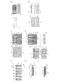
図2は、本発明にかかる針一体型バイオセンサーの一製造例を示す図である。a)は図1と同様にの手法により光硬化型の軟質シートに予め光硬化処理を施した軟質シート1の一方の表面上に導電体7,7が6組形成され、またレジスト6のパターンが示されている。b)は導電体を形成した一方の硬化部43上にレジスト6が設けられた状態がi)正面図およびii)背面図でそれぞれ示され、c)では接着剤層5のパターンがレジスト層6の表面に設けられている様子がi)正面図およびii)背面図でそれぞれ示している。ここで、レジスト層6および接着剤層5は試料搬送路および電極反応部を形成するためのスペーサー2としても設けられている。d)では、穿刺針20を配置させてから、2箇所の硬化基板部43の間が折畳みに必要な軟質部42となって硬化基板部43同士が重なり合うことで、e)に示す針一体型バイオセンサー単位40を形成する。この際、バイオセンサー内部を陰圧とするために、陰圧または真空の雰囲気下で、軟質部42での折畳みが行われる。ここではすでに針一体型バイオセンサー単位40が個々に分断されている状態がi)正面図およびii)背面図でそれぞれ示されている。さらに、e)では穿刺によって得た採血を無駄なくセンサー内に導入するために採血導入ガイド36が設けられている。f)では分断後の各針一体型バイオセンサー単位40を示し、これらのA-A’断面およびB-B’断面は、それぞれg)およびh)に示されている。g)では軟質シート1に折畳まれた内部のレジスト6および接着剤層5の空きスペースに電極10の反応層13および試料搬送路8が設けられている他、内部を真空に保つための空間26が設けられ、電極反応部13とは通気フィルター25で仕切られている。h)で示した断面には軟質シート1に折畳まれた内部の導電体7、レジスト層6および接着剤層5が積層されてと穿刺針の支持体19が接着剤層5内に固定されており、この部分には空間がない。このような構成により形成される針一体型バイオセンサー29であると、図1と同様に硬質な基板の折畳みに必要とされるミシン目などの形成が不要であるといったすぐれた効果を奏する。さらに、電気絶縁性基板およびカバーを繋ぐ部分が軟質基板であるために、バイオセンサーの内部に格納されている穿刺針が使用時に容易に該基板を突き抜け、非検体の皮膚を穿刺することができるといった特徴も有している。また図1と同様に、光硬化型の軟質シートの代わりに熱硬化型の軟質シートを用い、電気絶縁性基板部分およびカバー部分のみを熱によって硬化させることもできる。
FIG. 2 is a diagram showing an example of manufacturing a needle-integrated biosensor according to the present invention. In a), six sets of
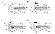
図3は、図2で示した針一体型バイオセンサーの一使用例を示す。a)には被検体の皮膚27に針一体型バイオセンサー29が穿刺する前の状態を示している。このとき、センサー内部は真空空間26の存在により外圧に対して陰圧に保たれている。b)は針一体型バイオセンサー29内に収められていた穿刺針20が軟質シート1の軟質部42と皮膚27を突き破った状態を示している。このとき採血導入ガイド36は皮膚27と密着することができる。この後、穿刺針は軟質シート材料の復元力によって被検体の皮膚から引き戻され、そのときに生じた軟質部42の貫通穴37を通じて採血24がバイオセンサーの試料搬送路へと導入される。この状態がc)に示されており、貫通穴37は採血24をセンサー内部へと送り込むための穿刺採血口32となっている。採血は採血導入ガイド36の存在とセンサー内部の真空状態の解除により円滑に行われる。採決後、血液成分の測定が行われている様子を図d)に示す。この状態では疎水性通気フィルター25の存在により、センサー内に搬送された採血は電極反応部13より奥にある空間26には送液されない。
FIG. 3 shows an example of use of the needle-integrated biosensor shown in FIG. a) shows a state before the needle-integrated
本発明にかかるバイオセンサーは、各種液体の成分濃度を、酵素などを利用して電気化学的に測定する、家庭内自己診断用の血糖計、尿糖計、糖化ヘモグロビン計、乳酸計、コレステロール計、尿酸計、タンパク質計、一塩基多型センサー、遺伝子診断に用いられるDNAチップ、他にアルコール計、グルタミン酸計、ピルビン酸計、pH計などに用いられるバイオセンサーとして有効に用いられる。 The biosensor according to the present invention is a home-use self-diagnosis blood glucose meter, urine sugar meter, glycated hemoglobin meter, lactic acid meter, cholesterol meter that electrochemically measures the component concentration of various liquids using an enzyme or the like. It is effectively used as a biosensor for use in uric acid meters, protein meters, single nucleotide polymorphism sensors, DNA chips used for genetic diagnosis, as well as alcohol meters, glutamic acid meters, pyruvic acid meters, pH meters and the like.
1 軟質シート
2 スペーサー
3 バイオセンサー
4 硬質基板
5 接着剤層
6 レジスト層
7 導電体
8 試料搬送路
9 試料導入口
10 電極
11 端子
12 空気排出口
13 電極反応部(試薬層)
14 折畳み成形体
15 カバー
16 ミシン目
19 穿刺針支持体
20 穿刺針
24 採血
25 通気フィルター
26 真空空間
27 皮膚
28 開放空間
29 針一体型バイオセンサー
32 穿刺採血口
33 穿刺針部
36 採血導入ガイド
37 貫通穴
38 採血導入ガイド形成鋳型
40 針一体型バイオセンサー単位
41 光
42 軟質部
43 硬化部
44 遮光板
DESCRIPTION OF
14 Folding molded
Claims (13)
電気絶縁性基板部分およびカバー部分が、1枚の軟質シートを、基板形成部およびカバー形成部の間を繋ぐ軟質部を残したうえで、該軟質部以外の基板形成部分およびカバー形成部分について硬化させることにより形成されることを特徴とするバイオセンサー。 In a biosensor in which electrodes, spacers, and a cover are sequentially formed on an electrically insulating substrate,
Curing the electrically insulating substrate portion and the cover portion, a single soft sheet, after leaving the soft portion connecting between the substrate forming part and the cover forming section, the substrate forming portion and the cover forming a portion other than the soft reacting section It is formed by making it biosensor.
Priority Applications (1)
| Application Number | Priority Date | Filing Date | Title |
|---|---|---|---|
| JP2006072444A JP4635260B2 (en) | 2006-03-16 | 2006-03-16 | Biosensor and manufacturing method thereof |
Applications Claiming Priority (1)
| Application Number | Priority Date | Filing Date | Title |
|---|---|---|---|
| JP2006072444A JP4635260B2 (en) | 2006-03-16 | 2006-03-16 | Biosensor and manufacturing method thereof |
Publications (2)
| Publication Number | Publication Date |
|---|---|
| JP2007248274A JP2007248274A (en) | 2007-09-27 |
| JP4635260B2 true JP4635260B2 (en) | 2011-02-23 |
Family
ID=38592744
Family Applications (1)
| Application Number | Title | Priority Date | Filing Date |
|---|---|---|---|
| JP2006072444A Expired - Fee Related JP4635260B2 (en) | 2006-03-16 | 2006-03-16 | Biosensor and manufacturing method thereof |
Country Status (1)
| Country | Link |
|---|---|
| JP (1) | JP4635260B2 (en) |
Families Citing this family (1)
| Publication number | Priority date | Publication date | Assignee | Title |
|---|---|---|---|---|
| CN110327059B (en) * | 2019-08-05 | 2020-06-23 | 浙江大学 | Electrode for biological sensitivity test and application |
Family Cites Families (14)
| Publication number | Priority date | Publication date | Assignee | Title |
|---|---|---|---|---|
| DK120991D0 (en) * | 1991-06-21 | 1991-06-21 | Novo Nordisk As | BLOOD SAMPLES |
| JP2000065777A (en) * | 1998-08-21 | 2000-03-03 | Nok Corp | Biosensor |
| JP2000116629A (en) * | 1998-10-15 | 2000-04-25 | Kdk Corp | Wearing body |
| US6413395B1 (en) * | 1999-12-16 | 2002-07-02 | Roche Diagnostics Corporation | Biosensor apparatus |
| EP1167538A1 (en) * | 2000-06-30 | 2002-01-02 | Schibli Engineering GmbH | Biosensor and method for its production |
| US6561989B2 (en) * | 2000-07-10 | 2003-05-13 | Bayer Healthcare, Llc | Thin lance and test sensor having same |
| JP4493181B2 (en) * | 2000-08-18 | 2010-06-30 | テルモ株式会社 | Component measuring device |
| US7691071B2 (en) * | 2001-01-19 | 2010-04-06 | Panasonic Corporation | Lancet-integrated sensor, measurer for lancet-integrated sensor, and cartridge |
| US20030212344A1 (en) * | 2002-05-09 | 2003-11-13 | Vadim Yuzhakov | Physiological sample collection devices and methods of using the same |
| US7544277B2 (en) * | 2003-06-12 | 2009-06-09 | Bayer Healthcare, Llc | Electrochemical test sensors |
| JP4038575B2 (en) * | 2003-07-25 | 2008-01-30 | 独立行政法人産業技術総合研究所 | Biosensor, biosensor device or biosensor storage method |
| JP2006010352A (en) * | 2004-06-22 | 2006-01-12 | Sumitomo Electric Ind Ltd | Sensor chip and manufacturing method thereof |
| JP4807493B2 (en) * | 2004-12-03 | 2011-11-02 | 住友電気工業株式会社 | Sensor chip and manufacturing method thereof |
| JP2007108104A (en) * | 2005-10-17 | 2007-04-26 | Sumitomo Electric Ind Ltd | Sensor chip and manufacturing method thereof |
-
2006
- 2006-03-16 JP JP2006072444A patent/JP4635260B2/en not_active Expired - Fee Related
Also Published As
| Publication number | Publication date |
|---|---|
| JP2007248274A (en) | 2007-09-27 |
Similar Documents
| Publication | Publication Date | Title |
|---|---|---|
| EP2426485B1 (en) | Method of making biosensors | |
| WO2007001003A1 (en) | Biosensor | |
| WO2007001001A1 (en) | Needle integrating biosensor | |
| JP4635260B2 (en) | Biosensor and manufacturing method thereof | |
| JP4665135B2 (en) | Biosensor manufacturing method | |
| JP4893921B2 (en) | Biosensor | |
| JP4670013B2 (en) | Biosensor and manufacturing method thereof | |
| JP4649594B2 (en) | Biosensor and manufacturing method thereof | |
| US12390134B2 (en) | Method of manufacturing a sensor for detecting an analyte in a body fluid | |
| JP4448940B2 (en) | Needle integrated biosensor | |
| JP4586210B2 (en) | Needle integrated biosensor | |
| US20140045202A1 (en) | Analyte Sensors and Methods for Making and Using the Same | |
| JP4706063B2 (en) | Needle integrated biosensor | |
| JP4595070B2 (en) | Needle integrated biosensor | |
| JP4686763B2 (en) | Needle integrated biosensor | |
| JP2007014646A (en) | Needle integrated biosensor | |
| JP4547535B2 (en) | Needle integrated biosensor | |
| JP4635258B2 (en) | Biosensor | |
| JP4853947B2 (en) | Biosensor | |
| JP4822511B2 (en) | Needle integrated biosensor | |
| JP4873536B2 (en) | Non-conductive needle | |
| JP4576628B2 (en) | Needle integrated biosensor | |
| JP2007256092A (en) | Biosensor |
Legal Events
| Date | Code | Title | Description |
|---|---|---|---|
| A621 | Written request for application examination |
Free format text: JAPANESE INTERMEDIATE CODE: A621 Effective date: 20080905 |
|
| A977 | Report on retrieval |
Free format text: JAPANESE INTERMEDIATE CODE: A971007 Effective date: 20100915 |
|
| A131 | Notification of reasons for refusal |
Free format text: JAPANESE INTERMEDIATE CODE: A131 Effective date: 20100928 |
|
| A521 | Request for written amendment filed |
Free format text: JAPANESE INTERMEDIATE CODE: A523 Effective date: 20100929 |
|
| TRDD | Decision of grant or rejection written | ||
| A01 | Written decision to grant a patent or to grant a registration (utility model) |
Free format text: JAPANESE INTERMEDIATE CODE: A01 Effective date: 20101102 |
|
| A01 | Written decision to grant a patent or to grant a registration (utility model) |
Free format text: JAPANESE INTERMEDIATE CODE: A01 |
|
| A61 | First payment of annual fees (during grant procedure) |
Free format text: JAPANESE INTERMEDIATE CODE: A61 Effective date: 20101104 |
|
| FPAY | Renewal fee payment (event date is renewal date of database) |
Free format text: PAYMENT UNTIL: 20131203 Year of fee payment: 3 |
|
| R150 | Certificate of patent or registration of utility model |
Free format text: JAPANESE INTERMEDIATE CODE: R150 |
|
| FPAY | Renewal fee payment (event date is renewal date of database) |
Free format text: PAYMENT UNTIL: 20131203 Year of fee payment: 3 |
|
| R250 | Receipt of annual fees |
Free format text: JAPANESE INTERMEDIATE CODE: R250 |
|
| S533 | Written request for registration of change of name |
Free format text: JAPANESE INTERMEDIATE CODE: R313533 |
|
| R350 | Written notification of registration of transfer |
Free format text: JAPANESE INTERMEDIATE CODE: R350 |
|
| R250 | Receipt of annual fees |
Free format text: JAPANESE INTERMEDIATE CODE: R250 |
|
| LAPS | Cancellation because of no payment of annual fees |