JP4154824B2 - Seedling planting machine - Google Patents
Seedling planting machine Download PDFInfo
- Publication number
- JP4154824B2 JP4154824B2 JP2000015949A JP2000015949A JP4154824B2 JP 4154824 B2 JP4154824 B2 JP 4154824B2 JP 2000015949 A JP2000015949 A JP 2000015949A JP 2000015949 A JP2000015949 A JP 2000015949A JP 4154824 B2 JP4154824 B2 JP 4154824B2
- Authority
- JP
- Japan
- Prior art keywords
- steering
- lever
- brake
- posture
- vehicle body
- Prior art date
- Legal status (The legal status is an assumption and is not a legal conclusion. Google has not performed a legal analysis and makes no representation as to the accuracy of the status listed.)
- Expired - Fee Related
Links
Images


Description
【0001】
【発明の属する技術分野】
この発明は、苗植機に関する。
【0002】
【発明が解決しようとする課題】
コンバインや田植機のような乗用作業機では、車体の前側から左右前車輪を操向する形態があるが、安全な走行を行わせることができなかった。
【0003】
【課題を解決するための手段】
この発明は、左右の前車輪(5)を備える車体(2)の後側にリフトリンク(13)を介して苗植装置(16)を設け、車体(2)の前部に左右の前車輪(5)を操向できるステアリングハンドル(1)を設け、車体(2)の前側に左右の前車輪(5)を操向できると共に走行クラッチ及びブレーキを操作できる操向レバー(3)を設けた苗植機において、主変速装置が苗植作業状態で且つ操向ブレーキペダル(11)を操作し且つステアリングハンドル(1)を所定以上操作したとき、パワステ(48)の駆動により前車輪(5)の切角が通常時よりも大きくなり、操向レバー(3)を、走行クラッチが切りになりブレーキが作動する起立した姿勢から走行クラッチが入りになりブレーキが解除される前側に倒した操向姿勢(C)に姿勢変更でき、操向姿勢(C)の操向レバー(3)から手を解放すると該操向レバー(3)が起立した姿勢に戻る構成とし、ステアリングハンドル(1)による前車輪(5)の最大操向角よりも操向姿勢(C)時の操向レバー(3)による前車輪(5)の最大操向角を小さく設定した苗植機とする。
【0004】
【発明の効果】
主変速装置が苗植作業状態で且つ操向ブレーキペダル11を操作し且つステアリングハンドル1を所定以上操作したとき、パワステ48の駆動により前車輪5の切角が通常時よりも大きくなるので、車体2が畦際等に達したときのステアリングハンドル1による操向を容易に行える。車体2を畦越えさせたり、車両に積み降しするような場合で、操縦者が車体2から降りた姿勢での操向を行うときは、車体2の前方から操向レバー3で左右の前車輪5を操向する。操向姿勢Cの操向レバー3から手を解放すると該操向レバー3を起立した姿勢に戻すことができ、操向レバー3による操向中に操縦者が転倒等によって操向レバー3の肥持を解除すると、自動的に走行クラッチが切られてブレーキが働くため、安全を図ることができる。
【0005】
また、この操向レバー3を前側に倒した操向姿勢(C)時に左右の前車輪5の最大操向角が小さく設定されているために、操縦者が車体2から降りた位置姿勢にあっても、安全な走行を行わせることができる。
【0006】
【発明の実施の形態】
苗植機を図面に基づいて説明する。
【0007】
図1〜図4において、苗植機の車体2は、前部のステアリングポスト4上のステアリングハンドル1によって操向自在の前車輪5と、操縦席6の後方に配置される後車輪7とを有して、該操縦席6下に搭載のエンジン8によって連動して走行できる四輪駆動走行形態である。9はステップフロア、10は左右一対の操向ブレーキペタルで、左右の後車輪7に各別に設けられる操向ブレーキ(図面省略)をれんどうする。11は走行クラッチペタル、12は変速レバーである。
【0008】
前記車体2の後側には、上下一対の平行リンクからなるリフトリンク13が、油圧力で伸縮されるリフトシリンダ14で上下回動可能に設けられ、この後端のヒッチリンク15に多条植形態の苗植装置16が連結される。又、この苗植装置16は車体2側のPTO軸(図面省略)を介して連動され、苗植付作動する。17は施肥装置で、車体2の後部の装着される。
【0009】
前記苗植装置16は、苗植フレーム18の下部にセンタフロート19とサイドフロート20を配置して、苗植装置16の重量を支持し土壌面を滑走しながら均平にする。後部には苗を分離保持して均平土壌面へ植付ける苗植付装置21を配置して、多条植付を行うことができる。上側にはマット状に育苗されたマット苗を収容して左右へ往復移動しながら後下部の苗取口部へ繰出す苗タンク22を設ける。この苗タンク22の苗取出口に苗植付装置21の植付爪部を作動させて、所定本数の苗を分離保持して植付ける。
【0010】
23は車体2の前部上に設けた補助苗載台で、苗タンク22へ補給するマット苗を収容する。24は操向マーカである。
【0011】
左右一対の前車輪5の車軸ケース25に一体の操向アーム26と、車体2前部のピットマンアーム27との間をタイロッド28で連結し、前記ステアリングハンドル1の操作で、パワステを介してアーム軸29を回動し、このアーム軸29と一体のピットマンアーム27を回動することができ、前車輪5を操向できる。
【0012】
操向レバー3は、該ピットマンアーム27の前側において、十字軸形態の竪軸30部の回りに左右方向Aに回動自在とし、横軸34部の回りに前後方向Bへ回動できる構成としている。左右方向Aへの回動では、ピットマンアーム27を回動して前車輪5を操向でき、前後方向Bへの回動では操向レバー3の出し入れを行わせる。
【0013】
該十字軸形態の竪軸30と横軸34とは一体的にこの竪軸30の回りに回動しうるもので、竪軸30部で車体2の前端部に枢支される。この横軸34の回りに操向レバー3の基部が前後方向Bに回動自在に支持される。この操向レバー3の基部から突出の係合アーム31を、ピットマンアーム27のアーム溝32に係合させる。操向レバー3でピットマンアーム27を回動することができる。
【0014】
ばね(図面省略)に抗して前側へ倒して操向姿勢Cとして左右方向Aへ回動するときは、車体2の前端部から突出の二又状の切角規制具38に当接して、操向レバー3による前車輪5の操向角度域が制限される。この切角規制具38の最大操向角は、ステアリングハンドル1による最大操向角よりも小さく設定している。
【0015】
又、操向レバー3は手を放せばばね力によって操向姿勢Cからステアリングポスト4に沿う後方に起立させることができる。
前記操向レバー3の先端にはグリップ35が形成されて、一方にはブレーキレバー36が、他方にはクラッチレバー37が操作可能に設けられる。
【0016】
苗植作業時、操縦者が操縦席6に搭乗して運転するときは、操向レバー3は収納姿勢Dにあって、係合アーム31はアーム溝32から外れた状態にある。ステアリングハンドル1の操作で前記ピットマンアーム27やタイロッド28等を介して左右の前車輪5を操向連動し、この操向角も大きく切ることができる。
【0017】
畦越え走行等のように操縦者が操向レバー3で操向するときは、車体2の前側から収納姿勢Dにある操向レバー3を前側へ倒して操向姿勢Cとして、係合アーム31をアーム溝32に係合させて、この操向レバー3を左右方向Aへ操作することによって、ピットマンアーム27を回動して、左右の前車輪5を操向できる。このとき、操向レバー3は、切角規制具38によって最大操向角度が必要最小限の安全な領域に規制されるために、前記ステアリングハンドル1による操向角よりも小さい切角領域での操向に制限することができる。
【0018】
図5,図6において、上例と異なる点は、前記操向レバー3の操作姿勢位置として、前記ステアリングポスト4に沿う起立位置を停止姿勢Eとし、更に後方のステップフロア9に沿う収容姿勢Dを設定する。又、操向レバー3は、車体2の中央正面から左右一側へ偏位した位置に、前記横軸34部を側方へ突出させて取付けている。この横軸34の左右両側部にはアーム39,40を有し、このアーム39,40と、後側に対向するクラッチペタル11のアーム41,ブレーキペタル10のアーム42との間を各々リンクロッド43,44で連結する。
【0019】
操向レバー3を操向姿勢Cにして操作作業中において、手を解放すると、操向レバー3はばね力によって停止位置Eに戻されて、リンクロッド43,44で連動のクラッチペタル11やブレーキペタル10が回動されて、クラッチが切られて前車輪5や後車輪7等の伝動が断たれると共に、左右の操向ブレーキが同時制動される。又、操向レバー3を操向姿勢Cに操作するとこれら走行クラッチは入りとなり、左右の操向ブレーキは解除される。
【0020】
このように操向レバー3による操向中に操縦者が転倒等によって操向レバー3の肥持を解除すると、自動的に走行クラッチが切られて左右の操向ブレーキが働くため、安全を図ることができる。
又、操向レバー3を収納姿勢Dへ倒すときは、例えば前記横軸34のアーム39,40からリンクロッド43,44の連結を外すことによって回動することができる。
【0021】
図7において、上例と異なる点は、車体2が畦際等に達したときの、前記ステアリングハンドル1による操向を容易にするものである。予めステアリングスイッチSW1をONしておき、ステアリングハンドル1の所定以上の操作によって、ステアリング切角センサである回転計45がこの切角を検出して、コントローラ46からの出力でモータ47を電動して、トルクジェネレータからなるパワステ48を駆動して、前車輪5の切角を通常時よりも大きくする構成としている。
【0022】
前記パワステ48の制御は、油圧無段変速装置等を設けて主変速伝動できる走行伝動形態において、苗植装置16による苗植作業を行う状態から旋回操向状態に入るときに行われる。
なお、前記ステアリングスイッチSW1は、前記のようなパワステ48の制御を行わせる場合に手動操作でONしておくものであるが、このようなステアリングスイッチSW1を、該主変速による苗植作業状態で、かつ前記操向ブレーキペタル11を踏んで片ブレーキを働かせて旋回行程に入ったときに、自動的にONさせる構成とすることによって、一層前記パワステの制御を容易に行わせることができる。
【0023】
図8において、上例と異なる点は、前記変速レバー12の中立位置N操作において、中立ブレーキ位置BLに操作することにより、左右の操向ブレーキを同時制動して、このブレーキ位置を固定できる構成としたものである。この変速レバー12の操作で走行クラッチの入り切りと左右の操向ブレーキの入り切りを同時に行わせる。苗植機をトラック荷台への積み降しするときの安全を図ることができる。
【0024】
前記変速レバー12は、クラッチレバーを兼用する形態とするもよい。変速軸51回りに、操作パネル49のレバーガイド50に沿って前後に操作回動でき、前側に操作すると前進位置Fとして前進走行でき、後側に操作すると前進位置Rとして後進走行できる。これらの中間の中立位置Nはクランク形体で、この中立位置Nの一側の中立ブレーキ位置BLが形成されて、変速レバー12を案内して係合できる。
【0025】
前記中立ブレーキ位置BLのレバーガイド50にはブレーキスイッチSW2が設けられて、このブレーキスイッチSW2を変速レバー12で押すことによってONしてブレーキ用の電磁バルブを作動して油圧回路によってブレーキを制動するものである。又、変速するときは、変速レバー12をブレーキ位置BLから移動することによってブレーキスイッチSW2をOFFして左右の操向ブレーキを解除し、変速走行できるものである。
【0026】
なお、前記変速レバー12に代えてクラッチレバーとする形態では、中立位置Nでは走行クラッチが切りとなり、前進位置F又は後進位置Rで走行クラッチが入りとなるように連動構成する。
又、この変速レバー12に代えて、副変速レバーを用いることもできる。
【図面の簡単な説明】
【図1】 操向レバー部の平面図。
【図2】 その側面図。
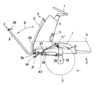
【図3】 苗植機の側面図。
【図4】 その平面図。
【図5】 操向レバー部の平面図。
【図6】 その側面図。
【図7】 ステアリングハンドル部のブロック図と、そのフローチャート。
【図8】 変速レバーガイド部の平面図、及び側面図。
【符号の説明】
1:ステアリングハンドル、2:車体、3:操向レバー、5:前車輪、11:操向ブレーキペダル、13:リフトリンク、16:苗植装置、48:パワステ、C:操向姿勢 [0001]
BACKGROUND OF THE INVENTION
The present invention relates to a seedling planting machine .
[0002]
[Problems to be solved by the invention]
In a riding work machine such as a combine or a rice transplanter, there is a form in which the left and right front wheels are steered from the front side of the vehicle body, but safe traveling cannot be performed.
[0003]
[Means for Solving the Problems]
The present invention provides a seedling planting device (16) via a lift link (13) on the rear side of a vehicle body (2) having left and right front wheels (5), and the left and right front wheels at the front of the vehicle body (2). A steering handle (1) that can steer (5) is provided, and a steering lever (3) that can steer the left and right front wheels (5) and operate the traveling clutch and brake is provided on the front side of the vehicle body (2) . In the seedling transplanter , when the main transmission is in the seedling planting state, the steering brake pedal (11) is operated, and the steering handle (1) is operated more than a predetermined amount, the front wheel (5) is driven by the power steering (48). Steering lever (3) is tilted to the front side when the travel clutch is engaged and the brake is released from the standing position where the travel clutch is disengaged and the brake is operated. Change posture to posture (C) When the hand is released from the steering lever (3) in the steering posture (C), the steering lever (3) returns to the standing posture, and the maximum steering of the front wheel (5) by the steering handle (1). A seedling transplanter is set in which the maximum steering angle of the front wheel (5) by the steering lever (3) in the steering posture (C) is set smaller than the steering angle .
[0004]
【The invention's effect】
When the main transmission is in the seedling planting operation, the
[0005]
In addition, since the maximum steering angle of the left and right
[0006]
DETAILED DESCRIPTION OF THE INVENTION
The seedling planting machine will be described based on the drawings.
[0007]
1 to 4, the
[0008]
A
[0009]
The
[0010]
[0011]
The
[0012]
The
[0013]
The
[0014]
When turning in the left-right direction A as the steering posture C against the spring (not shown) against the spring, it comes into contact with the bifurcated cut
[0015]
Moreover, the
A
[0016]
At the time of seedling planting work, when the operator gets on the
[0017]
When the operator steers with the
[0018]
5 and 6, the difference from the above example is that the operation posture position of the
[0019]
When the
[0020]
As described above, when the operator releases the holding of the
Further, when the
[0021]
In FIG. 7 , the difference from the above example is that steering by the steering handle 1 is facilitated when the
[0022]
The
The steering switch SW1 is turned on manually when the
[0023]
In FIG. 8 , the difference from the above example is that the left and right steering brakes can be braked simultaneously by operating to the neutral brake position BL in the neutral position N operation of the
[0024]
The
[0025]
A brake switch SW2 is provided in the
[0026]
In the form of a clutch lever instead of the
Further, instead of the
[Brief description of the drawings]
FIG. 1 is a plan view of a steering lever portion.
FIG. 2 is a side view thereof.
FIG. 3 is a side view of a seedling planting machine.
FIG. 4 is a plan view thereof.
FIG. 5 is a plan view of the steering lever.
FIG. 6 is a side view thereof.
FIG. 7 is a block diagram of a steering handle portion and a flowchart thereof.
FIGS. 8A and 8B are a plan view and a side view of a transmission lever guide portion . FIGS.
[Explanation of symbols]
1: Steering handle, 2 : Car body, 3 : Steering lever , 5 : Front wheel , 11: Steering brake pedal, 13: Lift link, 16: Seedling device, 48: Power steering, C: Steering posture
Claims (1)
Priority Applications (1)
| Application Number | Priority Date | Filing Date | Title |
|---|---|---|---|
| JP2000015949A JP4154824B2 (en) | 2000-01-25 | 2000-01-25 | Seedling planting machine |
Applications Claiming Priority (1)
| Application Number | Priority Date | Filing Date | Title |
|---|---|---|---|
| JP2000015949A JP4154824B2 (en) | 2000-01-25 | 2000-01-25 | Seedling planting machine |
Publications (3)
| Publication Number | Publication Date |
|---|---|
| JP2001206228A JP2001206228A (en) | 2001-07-31 |
| JP2001206228A5 JP2001206228A5 (en) | 2005-10-27 |
| JP4154824B2 true JP4154824B2 (en) | 2008-09-24 |
Family
ID=18543164
Family Applications (1)
| Application Number | Title | Priority Date | Filing Date |
|---|---|---|---|
| JP2000015949A Expired - Fee Related JP4154824B2 (en) | 2000-01-25 | 2000-01-25 | Seedling planting machine |
Country Status (1)
| Country | Link |
|---|---|
| JP (1) | JP4154824B2 (en) |
Families Citing this family (2)
| Publication number | Priority date | Publication date | Assignee | Title |
|---|---|---|---|---|
| JP2007089452A (en) * | 2005-09-28 | 2007-04-12 | Kubota Corp | Riding type paddy field working machine |
| JP5510589B2 (en) * | 2013-05-20 | 2014-06-04 | 井関農機株式会社 | Seedling transplanter |
-
2000
- 2000-01-25 JP JP2000015949A patent/JP4154824B2/en not_active Expired - Fee Related
Also Published As
| Publication number | Publication date |
|---|---|
| JP2001206228A (en) | 2001-07-31 |
Similar Documents
| Publication | Publication Date | Title |
|---|---|---|
| JP2008074236A5 (en) | ||
| JP2008074236A (en) | Working vehicle | |
| JP4154824B2 (en) | Seedling planting machine | |
| JP2008154487A (en) | Riding-type under-trellis work vehicle | |
| JP4581155B2 (en) | Passenger work vehicle | |
| JP4271923B2 (en) | Passenger rice transplanter | |
| JP3596349B2 (en) | Passenger work vehicle | |
| JPH0620867B2 (en) | Vehicle brake operating device | |
| JP4848572B2 (en) | Passenger work vehicle | |
| JP2005096577A (en) | Operation device for riding type working machine | |
| JP3497411B2 (en) | Travel shifting structure of paddy field vehicle | |
| JP3903551B2 (en) | Steering control device for work vehicle | |
| JP4297924B2 (en) | Riding machine | |
| JP3948830B2 (en) | Ground-operated equipment for riding farm equipment | |
| JP4793475B2 (en) | Passenger work vehicle | |
| JP4423873B2 (en) | Seedling planting machine | |
| JP2003102217A (en) | Riding type rice transplanter | |
| JP4985869B2 (en) | Passenger work vehicle | |
| JPS6211260Y2 (en) | ||
| JP2000335453A5 (en) | ||
| JPS6231297Y2 (en) | ||
| JPS6232902Y2 (en) | ||
| JP4930549B2 (en) | Passenger work vehicle | |
| JP4141221B2 (en) | Front-wheel steering structure for riding-type work machines | |
| JP2001278094A (en) | Riding paddy field working machine |
Legal Events
| Date | Code | Title | Description |
|---|---|---|---|
| A521 | Written amendment |
Free format text: JAPANESE INTERMEDIATE CODE: A523 Effective date: 20050830 |
|
| A621 | Written request for application examination |
Free format text: JAPANESE INTERMEDIATE CODE: A621 Effective date: 20050922 |
|
| A977 | Report on retrieval |
Free format text: JAPANESE INTERMEDIATE CODE: A971007 Effective date: 20070830 |
|
| A131 | Notification of reasons for refusal |
Free format text: JAPANESE INTERMEDIATE CODE: A131 Effective date: 20080226 |
|
| A521 | Written amendment |
Free format text: JAPANESE INTERMEDIATE CODE: A523 Effective date: 20080425 |
|
| TRDD | Decision of grant or rejection written | ||
| A01 | Written decision to grant a patent or to grant a registration (utility model) |
Free format text: JAPANESE INTERMEDIATE CODE: A01 Effective date: 20080617 |
|
| A01 | Written decision to grant a patent or to grant a registration (utility model) |
Free format text: JAPANESE INTERMEDIATE CODE: A01 |
|
| A61 | First payment of annual fees (during grant procedure) |
Free format text: JAPANESE INTERMEDIATE CODE: A61 Effective date: 20080630 |
|
| FPAY | Renewal fee payment (event date is renewal date of database) |
Free format text: PAYMENT UNTIL: 20110718 Year of fee payment: 3 |
|
| R150 | Certificate of patent or registration of utility model |
Free format text: JAPANESE INTERMEDIATE CODE: R150 |
|
| FPAY | Renewal fee payment (event date is renewal date of database) |
Free format text: PAYMENT UNTIL: 20110718 Year of fee payment: 3 |
|
| FPAY | Renewal fee payment (event date is renewal date of database) |
Free format text: PAYMENT UNTIL: 20140718 Year of fee payment: 6 |
|
| LAPS | Cancellation because of no payment of annual fees |