JP4154070B2 - Rear cushion unit mounting structure for scooter type vehicles - Google Patents
Rear cushion unit mounting structure for scooter type vehicles Download PDFInfo
- Publication number
- JP4154070B2 JP4154070B2 JP12131699A JP12131699A JP4154070B2 JP 4154070 B2 JP4154070 B2 JP 4154070B2 JP 12131699 A JP12131699 A JP 12131699A JP 12131699 A JP12131699 A JP 12131699A JP 4154070 B2 JP4154070 B2 JP 4154070B2
- Authority
- JP
- Japan
- Prior art keywords
- frame
- cushion
- portions
- mounting
- main
- Prior art date
- Legal status (The legal status is an assumption and is not a legal conclusion. Google has not performed a legal analysis and makes no representation as to the accuracy of the status listed.)
- Expired - Fee Related
Links
Images


Description
【0001】
【発明の属する技術分野】
本発明は、メインフレームに揺動可能に支承されるパワーユニットに後輪が軸支されるともにリヤクッションユニットの下端部が連結され、前記リヤクッションユニットの上端に設けられるクッション側ブラケットが、前記メインフレームの後部の主要部であるフレーム主部に設けられるクッション取付部に取付けられるスクータ型車両において、リヤクッションユニットのメインフレームへの取付構造の改良に関する。
【0002】
【従来の技術】
従来、かかるスクータ型車両は、たとえば特開平10−218065号公報等で既に知られている。
【0003】
【発明が解決しようとする課題】
ところが、上記従来のものでは、クッション取付部がフレーム主部から下方に突出するようにしてフレーム主部に設けられている。このため、リヤクッションユニットの上下方向長さが比較的短く、リヤクッションユニットのストロークが比較的小さくなっており、運転者の乗心地を向上するためには、リヤクッションユニットのストロークをより大きくすることが望まれる。
【0004】
本発明は、かかる事情に鑑みてなされたものであり、リヤクッションユニットのストロークをより大きくして、運転者の乗心地を向上し得るようにしたスクータ型車両におけるリヤクッションユニットの取付構造を提供することを目的とする。
【0005】
【課題を解決するための手段】
上記目的を達成するために、請求項1記載の発明は、メインフレームに揺動可能に支承されるパワーユニットに後輪が軸支されるともにリヤクッションユニットの下端部が連結され、前記リヤクッションユニットの上端に設けられるクッション側ブラケットが、前記メインフレームの後部を構成するフレーム主部に設けられるクッション取付部に取付けられるスクータ型車両において、前記クッション側ブラケットを挿通せしめる開口部を有する前記フレーム主部と、前記開口部を跨いで該フレーム主部よりも上方に隆起するクッション取付部とが互いに一体に鋳造成形され、前記クッション取付部には、これを横切る取付孔が形成されると共に、その取付孔にゴムブッシュが装着され、前記クッション取付部を挟む前記クッション側ブラケットが前記クッション取付部に、前記ゴムブッシュと、該ゴムブッシュ及びクッション側ブラケットを貫通して車両一側方より締付操作可能な第1のボルトとを介して取付けられることを特徴とする。
【0006】
かかる構成によれば、リヤクッションユニットが上端に備えるクッション側ブラケットをより高い位置に設定することが可能であり、リヤクッションユニットのストロークをより大きくして、運転者の乗心地を向上することができる。
【0007】
また請求項2記載の発明は、上記請求項1記載の発明の構成に加えて、前記メインフレームと共働して車体フレームを構成するサブフレームを取付けるためのボス部が前記フレーム主部に一体に形成されると共に、該ボス部を貫通する第2のボルトにより前記サブフレームが前記フレーム主部に締結され、前記ボス部は、前記クッション取付部の、前記フレーム主部に接続される一端部の側方に配置されていて、一部が車両側面視で前記一端部と重なっていることを特徴し、かかる構成によれば、フレーム主部から隆起するクッション取付部の強度をサブフレームで補強することができる。
【0008】
また請求項3記載の発明は、上記請求項2記載の発明の構成に加えて、前記第1及び第2のボルトは、各々の軸線相互が平行に配置されていて、車両の同一側方側より締付操作可能であることを特徴とする。
【0009】
【発明の実施の形態】
以下、本発明の実施形態を、添付図面に示す本発明の一実施例に基づいて説明する。
【0010】
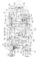
図1〜図24は本発明の一実施例を示すものであり、図1はスクータ型車両の側面図、図2はスクータ型車両の前部拡大側面図、図3はスクータ型車両の後部拡大側面図、図4は収納ボックスおよび燃料タンクを省略した状態での図3の4矢視図、図5は前部フレームおよび後部フレームを相互に分離した状態での斜視図、図6は前部フレームの拡大側面図、図7は図6の7矢視図、図8は図6の8−8線拡大断面図、図9は図7の9−9線拡大断面図、図10は図7の10−10線拡大断面図、図11は後部フレームの拡大側面図、図12は図11の12矢視図、図13は図12の13−13線拡大断面図、図14は車体フレームへのエンジンの揺動支持部を示す一部切欠き側面図、図15は図14の15−15線断面図、図16はリヤクッションユニットの車体フレームへの取付部を示す側面図、図17は図16の17−17線断面図、図18は図17の18−18線断面図、図19はサブフレームの側面図、図20は図19の20矢視図、図21は図1の21矢視拡大図、図22は図21の22−22線断面図、図23は図22の23−23線断面図、図24は後部フレームの中心線に対するヘッドパイプ部の位置のばらつきを説明するための図であって、(a)はメインフレームの側面図、(b)は(a)のB矢視図である。
【0011】
先ず図1において、スクータ型車両の車体フレームFは、メインフレーム21と、該メインフレーム21の後部に締結されるサブフレーム22とで構成されるものであり、メインフレーム21は、アルミ合金等で鋳造成形される前部フレーム23の後端部に、アルミ合金等で鋳造成形される後部フレーム24の前端部が締結されて成り、後部フレーム24の後端部に前記サブフレーム22が締結される。すなわち車体フレームFは、その前方側から順に前部フレーム23、後部フレーム24およびサブフレーム22が締結されて成るものである。
【0012】
図2を併せて参照して、前部フレーム23がその前端に備えるヘッドパイプ部25には、前輪WFを跨ぐフロントフォーク28が操向可能に支承される。前記フロントフォーク28の下端は前輪WFの車軸31よりも前方に配置されており、該フロントフォーク28の下端に一端が連結されるリンク29の他端が前記車軸31に連結され、フロントフォーク28の上下方向中間部およびリンク29の中間部間にフロントクッション30が設けられる。またフロントフォーク28の上端には操向ハンドル32が連結される。
【0013】
図3および図4を併せて参照して、後輪WRの前方側に配置されるエンジンEと、後輪WRの左側方に配置される無段変速機Mとから成るパワーユニットPが、後部フレーム24の前後方向中間部に上下揺動可能に支承される。エンジンEは、たとえばシリンダを車体前方に向けてほぼ水平に配置した水冷式の単気筒4サイクルエンジンであり、無段変速機Mは、たとえばベルト式のものである。
【0014】
パワーユニットPの後部には後輪WRが軸支され、パワーユニットPの後部と、メインフレーム23の後部すなわち後部フレーム24との間にはリヤクッションユニット33が設けられる。パワーユニットPの後部には、後輪WRの上部側方に配置されるエアクリーナ34が取付けられており、このエアクリーナ34は、気化器35を介してエンジンEに接続される。またエンジンEからの排気ガスを導く排気管36がエンジンEから後輪WRの右側方側に延出されており、この排気管36は、後輪WRの右側方に配置される排気マフラー37に接続される。さらにエンジンEにはスタンド38が回動可能に支持され、ラジエータ44がパワーユニットPの右側方に配置される。
【0015】
図5〜図7を併せて参照して、前部フレーム23は、ヘッドパイプ部25と、該ヘッドパイプ部25から後下りに延びるダウンフレーム部26と、該ダウンフレーム部26の下端から後方に延びる左右一対のフロア支持フレーム部271 ,272 とを一体に有して、鋳造成形される。
【0016】
ダウンフレーム部26は、図8で示すように、前方および下方を開放した溝形に形成されるものであり、溝内に配置される複数のリブ26a…がダウンフレーム部26に一体に設けられる。
【0017】
左右一対のフロア支持フレーム部271 ,272 は、上方を開放した溝形にそれぞれ形成されて一直線状に延びる。しかも両フロア支持フレーム部271 ,272 の前端部は、ダウンフレーム部26の下端両側にそれぞれ配置され、ダウンフレーム部26の下端前面よりも前方に膨らんだ一対の彎曲部501 ,502 を介して、前記両フロア支持フレーム部271 ,272 の前端部が、ダウンフレーム部26の下端両側にそれぞれ連設される。また両彎曲部501 ,502 も上方を開放した溝形に形成されており、両彎曲部501 ,502 の相互に対向する内側部には、外側方側に凹んだ凹部51がそれぞれ設けられる。
【0018】
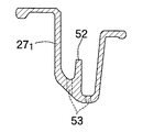
図9において、両フロア支持フレーム部271 ,272 には、前後方向に延びるリブ52,52がそれぞれ一体に設けられる。また両フロア支持フレーム部271 ,272 の底部には、フロア支持フレーム部271 ,272 内に浸入した水を排出するための一対の排水孔53,53が前記リブ52の両側に配置されるようにしてそれぞれ設けられる。さらに彎曲部501 ,502 の底部にも排水孔54がそれぞれ設けられる。
【0019】
両フロア支持フレーム部271 ,272 の後端部間は、上方に開放した略U字状に形成される補強フレーム部55を介して相互に一体に連結される。
【0020】
両フロア支持フレーム部271 ,272 の後端部には、前下がりに傾斜した前部締結板部561 ,562 が一体に設けられており、両前部締結板部561 ,562 には、ボルト挿通孔57,57が一対ずつ設けられる。而して一方の前部締結板部561 には、図10で示すように、両ボルト挿通孔57,57間の中間部下面に開口する単一の嵌合凹部58がボルト挿通孔57…と平行な軸線を有するようにして設けられ、他方の前部締結板部562 には、両ボルト挿通孔57,57間の中間部下面に開口する一対の嵌合凹部58,58がボルト挿通孔57…と平行な軸線を有するようにして設けられる。
【0021】
図11および図12を併せて参照して、後部フレーム24は、上方から見たときに前方を開いた略U字状に形成されるフレーム主部24aと、該フレーム主部24aの中間部両側間を連結する補強フレーム部24bとを一体に有して、基本的には後上がりに傾斜するようにして鋳造成形される。
【0022】
この後部フレーム24におけるフレーム部24aの両側前端には、前記前部フレーム23の後端の前部締結板部561 ,562 に下方から重合するようにして、前下がりに傾斜した後部締結板部611 ,612 がそれぞれ一体に設けられる。
【0023】
両後部締結板部611 ,612 には、前部フレーム23の前部締結板部561 ,562 に設けられたボルト挿通孔57,57にそれぞれ対応する一対ずつのボルト挿通孔62,62が設けられる。一方の後部締結板部611 には、図13で示すように、ボルト挿通孔62…の軸線と平行な軸線を有して両ボルト挿通孔62,62間の中間部上面から上方に突出する単一の嵌合突部63が、前部締結板部561 に設けられた嵌合凹部58に嵌合するようにして突設され、他方の後部締結板部612 には、ボルト挿通孔62…の軸線と平行な軸線を有して両ボルト挿通孔62,62間の上面から上方に突出する一対の嵌合突部63,63が、前部締結板部562 に設けられた嵌合凹部58,58に嵌合するようにして突設される。
【0024】
前部締結板部561 ,562 と、それらの前部締結板部561 ,562 に下方から重合する後部締結板部611 ,612 とは、各ボルト挿通孔57,62;57,62…に挿通されるボルト64,64…にナット65,65…を螺合して締付けることにより相互に締結される。しかも前部および後部締結板部561 ,562 ;611 ,612 の締結状態で、各嵌合突部63…が各嵌合凹部58…にそれぞれ嵌合され、フロア支持フレーム部271 ,272 の後端および後部フレーム24の前端の締結部の3箇所以上の複数箇所、この実施例では3箇所で各嵌合突部63…が各嵌合凹部58…に嵌合されることになる。
【0025】
また前部締結板部561 および後部締結板部611 、ならびに前部締結板部562 および後部締結板部612 をそれぞれ締結する複数(この実施例では一対)ずつのボルト64,64の少なくとも1つの軸線の延長線L、この実施例では一対のボルト64,64の軸線の延長線L,Lが、図1で示すように、操向操作を可能としてヘッドパイプ部25で支承される操向ハンドル32の上端と、前輪WFの車軸31との間を通るように設定されている。而して相互に嵌合した嵌合突部63…および嵌合凹部58…は、一対のボルト64,64間に配置されるものであり、ボルト64…と平行な軸線を有するものであるので、嵌合突部63…および嵌合凹部58…の軸線の延長線も操向ハンドル32の上端および前輪WFの車軸31間を通ることになる。
【0026】
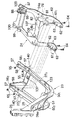
ところで、パワーユニットPにおけるエンジンEは、防振リンク66を介して車体フレームFにおける後部フレーム24に支承されるものであり、この防振リンク66の構造について、図14および図15を参照しつつ説明する。
【0027】
防振リンク66は、エンジンEに設けられる左右一対のエンジン側ブラケット671 ,672 と、各エンジン側ブラケット671 ,672 に一端が揺動可能に連結されるとともに他端が後部フレーム24のフレーム主部24aに揺動可能に連結されて気化器35よりも前方側に配置される左右一対のリンク681 ,682 と、両リンク681 ,682 間を連結するクロスメンバー69と、後部フレーム24における補強フレーム部24bに当接するようにして一方の前記リンク681 に設けられる一対のストッパラバー70,71と備える。
【0028】
エンジン側ブラケット671 ,672 は、上方に突出するようにしてエンジンEに設けられており、これらのエンジン側ブラケット671 ,672 には、装着孔72,72が同軸に設けられ、各装着孔72,72にはゴムブッシュ73,73が圧入され、両ゴムブッシュ73,73間には円筒状のスペーサ74が介装される。両ゴムブッシュ73,73およびスペーサ74には、一方のリンク681 の外側面に係合する頭部75aを備えるボルト75が挿通され、他方のリンク682 からの前記ボルト75の突出部に、他方のリンク682 の外側面に係合するナット84が螺合される。すなわち、両リンク681 ,682 の一端に連結されて水平に配置されるボルト75がゴムブッシュ73,73を介してエンジン側ブラケット671 ,672 に支承されることになる。
【0029】
後部フレーム24のフレーム主部24aにおける中間部両側には、支持孔76,76が同軸に設けられ、各支持孔76,76にはゴムブッシュ77,77が圧入される。而して両リンク681 ,682 の他端に設けられて前記ボルト75と平行であるボルト78,78が前記ゴムブッシュ77,77を介して前記フレーム主部24aに揺動可能に支承される。
【0030】
一方のリンク681 において、ボルト75およびボルト78の軸線を結ぶ直線よりも前方側にはボックス状のラバー支持部79が設けられ、このラバー支持部79に装着されるストッパラバー70を当接させる当接面81が、後部フレーム24における補強フレーム部24bの下面に形成される。また前記リンク681 において、ボルト75およびボルト78の軸線を結ぶ直線よりも後方側にはボックス状のラバー支持部80が設けられ、このラバー支持部80に装着されるストッパラバー71を当接させる当接面82が、前記補強フレーム部24bの下面に形成される。
【0031】
両リンク681 ,682 を連結するクロスメンバー69は、下方を開いた略U字状に形成されており、両リンク681 よりも後方側に配置される前記気化器35と、エンジンEとの間を接続する吸気管83を跨ぐように配置される。
【0032】
而して、かかる防振リンク66では、パワーユニットPのエンジンEからボルト75に作用する荷重は、ゴムブッシュ73,73の弾性変形によって吸収されるとともに、ストッパラバー70,71が当接面81,82に押付けられて弾性変形することにより吸収され、さらにゴムブッシュ77,77の弾性変形によっても吸収される。
【0033】
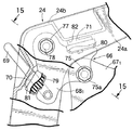
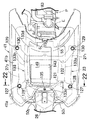
車体フレームFにおけるメインフレーム21の後部には、パワーユニットPに下端部が連結されたリヤクッションユニット33の上端部が取付けられるが、そのリヤクッションユニット33の上端部のメインフレーム21への取付構造について、図16〜図18を参照しつつ説明する。
【0034】
リヤクッションユニット33の上端には、上方に開放した略U字形に形成されたクッション側ブラケット86が設けられる。一方、メインフレーム21の後部すなわち後部フレーム24の主要部であるフレーム主部24aの後部において、リヤクッションユニット33に対応する部分には、前記クッション側ブラケット86を挿通せしめる開口部87が設けられる。
【0035】
また前記フレーム主部24aには、前記開口部87を跨いでフレーム主部24aよりも上方に隆起するクッション取付部88が一体に設けられており、前記クッション側ブラケット86はクッション取付部88を挟むように配置される。
【0036】
クッション取付部88に設けられる取付孔89にはゴムブッシュ90が圧入され、該ゴムブッシュ90を貫通するボルト91がクッション側ブラケット86に螺着される。すなわちクッション側ブラケット86はゴムブッシュ90を介してクッション取付部88に取付けられる。
【0037】
図19および図20において、サブフレーム22は、金属製のパイプの加工により構成されるものであり、上方から見たときに前方を開いた略U字状に形成される枠部92と、上下に延びるようにして枠部92の前端に中間部が溶接される一対の立上がり部93,93と、立上がり部93,93の下端に一端が溶接されるとともに枠部92に他端が溶接される一対の補強部94,94とを備え、車体フレーム21の前後方向に延びる中心線に関して左右対称に形成される。
【0038】
各立上がり部93,93の下端部、ならびにそれらの立上がり部93,93の下端部に重なった補強部94,94の一端部にはボルト挿通孔97…が設けられ、各補強部94,94の中間部にはボルト挿通孔98…が設けられる。一方、後部フレーム24におけるフレーム主部24aには、両ボルト挿通孔97…に対応した一対のボス部99,99と、両ボルト挿通孔98…に対応した一対のボス部100,100とが、フレーム主部24aから上方に隆起するようにして一体に設けられており、ボルト101…およびナット102…により、サブフレーム22が前記各ボス部99,99;100,100に取付けられる。しかもフレーム主部24aの左側に配置されるボス部99,100は、クッション取付部88のフレーム主部24aへの連設部に対応する位置に配置されており、サブフレーム22が、クッション取付部88のフレーム主部24aへの連設部に対応する位置で、フレーム主部24aに締結されることになる。而して前記ボス部100は、図4,図5,図16,図18にも示されるようにクッション取付部88の、フレーム主部24aに接続される一端部の側方に配置されていて、一部が車両側面視で前記一端部と重なっている。
【0039】
後部フレーム24およびサブフレーム22には、ヘルメット等を収納可能な収納ボックス39が、前記エンジンEおよび気化器35の上方に配置されるようにして支持される。
【0040】
収納ボックス39の前方寄り下端には、図15で明示するように、下方に突出する一対の脚部105,106が突設される。一方、後部フレーム24における補強フレーム部24bの上面には、前記各脚部105,106をそれぞれ受ける支持凹部107,108が設けられており、支持凹部107,108で受けられた脚部105,106が、ボルト109,109およびナット110,110で後部フレーム24の補強フレーム部24bに締結される。而して補強フレーム部24bおよび収納ボックス39の底部は、それら24b,39の下方に配置される吸気管83および気化器35との干渉を回避するために、スクータ型車両の走行方向前方を向いた状態で右下りに傾斜するように形成されている。
【0041】
またサブフレーム22における両立上がり部93…の上端には、平坦な取付板部111がそれぞれ設けられ、各取付板部111…には、ナット112がそれぞれ溶接される。これらの取付板部111…上には、収納ボックス39の後端が載せられ、ナット112…にそれぞれ螺合するボルト113…(図1参照)を締付けることにより、収納ボックス39の後端がサブフレーム22に取付けられる。
【0042】
このようにして、収納ボックス39が、エンジンEおよび気化器35の上方で後部フレーム24およびサブフレーム22に支持されるのであるが、前記防振リンク66におけるクロスメンバー69は、収納ボックス39およびエンジンE間に配置される。
【0043】
収納ボックス39よりも後方側で前記サブフレーム22上には燃料タンク40が支持される。燃料タンク40の支持のために、サブフレーム22における枠部92の後端上面には取付板114が溶接され、枠部92の中間部両側には取付板115,115が溶接される。前記取付板114には一対のナット116,116が溶接されており、前記取付板115,115にはナット117がそれぞれ溶接される。而して枠部92内に配置される燃料タンク40の後部は、両ナット116,116にそれぞれ螺合するボルト118…(図1,2参照)で前記取付板114上に支持され、また燃料タンク40の両側部は、前記各ナット117…にそれぞれ螺合するボルト119…(図1,2参照)で前記取付板115,115上に支持される。
【0044】
車体フレームFは、合成樹脂製の車体カバー41で覆われるものであり、この車体カバー41は、運転者の足の前方を覆うレッグシールド41aと、運転者の足を載せるためのステップフロア41bと、ステップフロア41bの下方を覆うアンダーカバー41cと、車体後部を両側から覆うサイドカバー41dとを備える。
【0045】
後部フレーム24およびサブフレーム22上に支持される収納ボックス39の大部分、ならびにサブフレーム22上に支持される燃料タンク40は、上記サイドカバー41dで覆われており、収納ボックス39を上方から覆い得るシート42がサイドカバー41dの上部に開閉可能に取付けられる。また燃料タンク40が備える燃料注入用のキャップ40aはサイドカバー41dの上部から上方に突出するように配置される。
【0046】
図2に特に注目して、ヘッドパイプ部25の背面部には、該ヘッドパイプ部25の背面に間隔をあけて対向する取付板部45が一体に設けられており、この取付板部45には、下方を開放した略U字状に形成されるナット支持部材46が上方から嵌合される。しかもナット支持部材46には、ヘッドパイプ部25の背面および取付板部45間に配置されるナット47が溶接される。一方、買物袋等を係合するためのフック48が、車体カバー41におけるレッグシールド41aの前記取付板部45に対応する部分に当接され、フック48、レッグシールド41a、ナット支持部材46および取付板部45に挿通されてフック48に係合するねじ部材49が前記ナット47に螺合される。
【0047】
図21〜図23において、前部フレーム23における両フロア支持フレーム部271 ,272 間には、前後方向に間隔をあけて一対のフロア支持板121,122がかけ渡される。
【0048】
両フロア支持フレーム部271 ,272 の前部寄りの部分には、ボルト挿通孔123,123が設けられ、それらのボルト挿通孔123,123に対応したナット124,124が溶接された略U字状のナット支持部材125,125が各フロア支持フレーム部271 ,272 に側方から嵌合される。而して、各ナット支持部材125,125上には、アンダーカバー支持部材126,126、フロア支持板121の長手方向両端部およびステップフロア41bの前部寄り両側部が載せられ、ステップフロア41b、フロア支持板121およびアンダーカバー支持部材126,126は、前記ナット125,125にボルト127,127が螺合されることにより、フロア支持フレーム部271 ,272 に共締めされる。しかもステップフロア41bにはボルト127,127の頭部が上方に突出することを回避するようにして、各ボルト127,127の頭部を収納する凹部128,128が設けられる。
【0049】
フロア支持板121の長手方向中央部には上方に隆起した隆起部121aが設けられており、ステップフロア41bの前端中央がレッグシールド41aの下端部とともに前記隆起部121aで支持される。
【0050】
フロア支持板121とともにステップフロア41bを下方から支持するフロア支持板122の長手方向両端部は、前記フロア支持板121と同様の構造で、ボルト129,129によりステップフロア41bとともに、フロア支持フレーム部271 ,272 に共締めされ、ボルト129,129の頭部を収納する凹部130,130がステップフロア41bに設けられる。而してフロア支持フレーム部271 ,272 の後部寄りの部分には、前記ボルト129,129を挿通せしめるためのボルト挿通孔140,140が設けられる。
【0051】
アンダーカバー41cは、前部フレーム23における両フロア支持フレーム部271 ,272 を下方から覆うように配置されるものであり、前記アンダーカバー支持部材126,126に、ボルト131…およびナット132…により締結される。
【0052】
前記両フロア支持フレーム部271 ,272 間には、上部を開放した箱形の物入れ133が配置される。この物入れ133の上端両側部には、両フロア支持フレーム部271 ,272 側に張出す支持鍔部133a,133bが一体に設けられ、それらの支持鍔部133a,133bの外端部に設けられる凹部134,135が、両フロア支持フレーム部271 ,272 の内側部上縁で受けられる。
【0053】
また物入れ133の上端前部には、ダウンフレーム部26の下部上面上に載せられる支持鍔部133cが一体に設けられ、該支持鍔部133cに挿通されるとともに、前記ダウンフレーム部26の下部に設けられるボルト挿通孔134に挿通されるボルト135と、該ボルト135に螺合されるナット136とにより、支持鍔部133cがダウンフレーム部26の下部に締結される。
【0054】
さらに物入れ133の後端下部には、補強フレーム部55の幅方向中央部に載せられる支持鍔部133dが一体に設けられ、該支持鍔部133dに挿通されるとともに、前記補強フレーム部55の幅方向中央部に設けられるボルト挿通孔137に挿通されるボルト138と、該ボルト138に螺合されるナット139とにより、支持鍔部133dが補強フレーム部55の幅方向中央部に締結される。
【0055】
物入れ133内の前方寄りの部分には、バッテリ143が収納される。このバッテリ143の前後で物入れ133に係合されているフック144,145に、バッテリ143に掛けられるベルト146の両端を係合することにより、バッテリ143が物入れ133内で固定配置される。
【0056】
前記バッテリ143よりも後方側で物入れ133内には、ラジエータリザーブタンク147が、固定配置される。
【0057】
物入れ133に対応する位置でステップフロア41bの中央部には開口部148が設けられており、この開口部148は、ねじ部材150でステップフロア41bに締結される蓋149で開閉可能に閉鎖され、閉鎖状態で蓋149の上面は、ステップフロア41bの上面と面一である。
【0058】
次にこの実施例の作用について説明すると、このスクータ型車両における車体フレームFは、前部フレーム23、後部フレーム24およびサブフレーム22が相互に締結されて成るものであり、各フレーム23,24,22のうちの少なくとも1つ、この実施例では前部フレーム23および後部フレーム24が、鋳造成形されて成るものである。したがって鋳造成形される前部フレーム23および後部フレーム24のいずれかを、車体フレームの一部を変更することで機種を異ならせるようにした多機種の自動二輪車に共用することで、機種変更による車体フレームの設計、製造コストの低減を図ることができる。しかも各フレーム23,24,22毎にモジュール化して各フレーム23,24,22毎の部品組付を行なうことが可能であり、組付完了後の3つのモジュールを相互に組付けてスクータ型の自動二輪車の組立を行なうことができるので、スクータ型車両の組付作業能率の向上にも寄与することができる。
【0059】
また前部フレーム23は、ヘッドパイプ部25、ダウンフレーム部26およびフロア支持フレーム部271 ,272 を一体に有して鋳造成形され、鋳造成形される後部フレーム24が前記フロア支持フレーム部271 ,272 の後端に締結され、金属製のパイプを加工して成るサブフレーム22が後部フレーム24の後端に締結されるので、設計、製造コストが多くはかからないサブフレーム22については、金属製のパイプの加工で機種変更に容易に対処することができる。
【0060】
前部フレーム23が備える左右一対のフロア支持フレーム部271 ,272 と、後部フレーム24との締結にあたって、フロア支持フレーム部271 ,272 の後端に設けられる前部締結板部561 ,562 に、後部フレーム24の前端に設けられて前部締結板部561 ,562 に重合する後部締結板部611 ,612 が締結されるのであるが、前部締結板部561 ,562 および後部締結板部611 ,612 は、図24(a)で示すように、ともに前下りに傾斜するように形成されている。したがって、両締結板部561 ,562 ;611 ,612 の締結面に平行な平面へのヘッドパイプ部25および前記締結面の投影図上では、図24(b)で示ように、締結板部561 ,562 ;611 ,612 の締結面がヘッドパイプ部25に比較的近接した位置に配置されることになる。このため、図24(b)で示すように、前部フレーム23の前部締結板部561 ,562 への後部フレーム24側の後部締結板部611 ,612 の組付誤差が生じて、後部フレーム24の幅方向中心線Cに対してヘッドパイプ部25の位置が傾斜するようにずれたとしても、後部フレーム24の幅方向中心線Cに対するヘッドパイプ部25の位置の変位量δ1 ,δ2 を比較的小さく抑えることができ、前輪WFおよび後輪WRの車体に対する位置合わせの精度を向上することができる。
【0061】
しかも前部締結板部561 および後部締結板部611 、ならびに前部締結板部562 および後部締結板部612 をそれぞれ締結する一対ずつのボルト64,64の少なくとも1つの軸線の延長線L、この実施例では一対のボルト64,64の軸線の延長線L,Lが、ヘッドパイプ部25で支承される操向ハンドル32の上端および前輪WFの車軸31間を通るように設定されていることにより、前記締結面がヘッドパイプ部25により近接した位置に配置されることになり、前部フレーム23への後部フレーム24の組付誤差が生じたとしても、後部フレーム24の幅方向中心線Cに対するヘッドパイプ部25の位置の変位量δ1 ,δ2 をより小さく抑えることができる。
【0062】
これに対し、前部フレーム23の後端および後部フレーム24の前端の締結面が図25(a)で示すように、前下りではなく、ほぼ水平である場合を想定すると、前部フレーム23の後端および後部フレーム24の前端の締結面に平行な平面へのヘッドパイプ部25および前記締結面の投影図上では、図25(b)で示ように、前記締結面がヘッドパイプ部25から比較的離反した位置に配置されることになり、前部フレーム23への後部フレーム24の組付誤差が生じたときには、後部フレーム24の幅方向中心線Cに対するヘッドパイプ部25の位置の変位量δ1 ,δ2 が比較的大きくなってしまうのである。
【0063】
また前部締結板部561 ,562 に後部締結板部611 ,612 が下方から重合されるので、フロア支持フレーム部271 ,272 の後端上方に後部フレーム24を配置するスペースを確保する必要がない。このためステップフロア41bをフロア支持フレーム部271 ,272 の後端上方まで配置することができ、ステップフロア41bのスペースを大きく設定することができる。
【0064】
またフロア支持フレーム部271 ,272 の後端に嵌合凹部58…が設けられ、後部フレーム24の前端に、前記嵌合凹部58…に嵌合する嵌合突部63…が突設されるので、前部フレーム23および後部フレーム24を相互に締結して組付ける際の組付け精度を向上することができる。
【0065】
しかもフロア支持フレーム部271 ,272 の後端および後部フレーム24の前端の締結部の3箇所以上の複数箇所、この実施例では3箇所に、嵌合凹部58…および嵌合突部63…が配置されることにより、前部フレーム23および後部フレーム24の組付け精度をより一層向上することができる。
【0066】
前部フレーム23において、ダウンフレーム部26は前方および下方を開放した溝形に形成されるので、ダウンフレーム部26の断面形状を減少させることなく前輪WFをダウンフレーム部26に近接、配置することができ、前輪WFおよびダウンフレーム部26の干渉を回避するとともにステップフロア41bのスペースを充分に確保しつつ、ホィールベースを短縮することができる。
【0067】
また左右一対のフロア支持フレーム部271 ,272 は上方を開放した溝形にそれぞれ形成されるので、車体フレームFに作用する外力の作用により両フロア支持フレーム部271 ,272 がそれらの上部開口面積を変化させるように撓むことで乗り心地の向上を図ることができる。
【0068】
しかもフロア支持フレーム部271 ,272 には、前後方向に延びるリブ52がそれぞれ設けられており、両フロア支持フレーム部271 ,272 が外力の作用により撓むことを可能としつつ、両フロア支持フレーム部271 ,272 の剛性が極端に低下することも防止することができる。
【0069】
さらにフロア支持フレーム部271 ,272 の前端部が、ダウンフレーム部26の下端両側にそれぞれ配置されるので、ステップフロア41bをダウンフレーム部26の下端両側まで配置することができ、ホィールベースを大きくすることなくステップフロア41bのスペースを前方側に充分に確保することができる。
【0070】
しかもフロア支持フレーム部271 ,272 の前端部が、ダウンフレーム部26の下端前面よりも前方に膨らんだ一対の彎曲部501 ,502 を介して、ダウンフレーム部26の下端両側にそれぞれ連設されるので、一直線状である一対のフロア支持フレーム部271 ,272 の前端部がそれぞれ配置されるにもかかわらず、ダウンフレーム部26および両フロア支持フレーム部271 ,272 の連設部、すなわち両彎曲部501 ,502 を前方側に膨らませるようにして、前記連設部の強度を充分に高めることができる。
【0071】
それに加えて、両彎曲部501 ,502 の相互に対向する内側部にそれぞれ設けられる凹部51…で前輪WFとの間の間隔を確保するようにして前輪WFを彎曲部501 ,502 側に近接配置することができ、したがって彎曲部501 ,502 を介して両フロア支持フレーム部271 ,272 の前端部がダウンフレーム部26に連設されることでホィールベースが大きくなってしまうことを回避することができる。
【0072】
パワーユニットPにおけるエンジンEを車体フレームFに揺動可能に支承する防振リンク66において、エンジンEに設けられる左右一対のエンジン側ブラケット671 ,672 および車体フレームFを揺動可能に連結する左右一対のリンク681 ,682 間を連結するクロスメンバー69は、下方を開いた略U字状に形成され、両リンク681 ,682 よりも後方側に配置される気化器35と、エンジンEとの間を接続する吸気管83を両リンク681 ,682 よりも前方側で跨ぐ位置に配置されている。したがって、気化器35が両リンク681 ,682 よりも前方側に配置されるものに比べて気化器35の配置上の自由度が高くなる。
【0073】
しかもエンジンEは、ほぼ水平に配置される4サイクルエンジンであり、シート42の下方で車体フレームFに取付けられる収納ボックス39およびエンジンE間に、クロスメンバー69が配置されることにより、収納ボックス39との干渉を回避してクロスメンバー69の自由な作動を確保するにあたり、シート42の位置が高くなること防止することができる。
【0074】
さらに車体フレームFにおけるメインフレーム21の後部の主要部であるフレーム主部24aに、リヤクッションユニット33が上端に備えるクッション側ブラケット86を挿通せしめる開口部87が設けられ、開口部87を跨いでフレーム主部24aよりも上方に隆起するクッション取付部88がフレーム主部24aに設けられ、クッション側ブラケット86がクッション取付部88に取付けられるので、クッション側ブラケット86をより高い位置に設定することが可能であり、リヤクッションユニット33のストロークをより大きくして、運転者の乗心地を向上することができる。
【0075】
しかもメインフレーム21と共働して車体フレームFを構成するサブフレーム22が、クッション取付部88のフレーム主部24aへの連設部に対応する位置でメインフレーム21に締結されるので、フレーム主部24から隆起するクッション取付部88の強度をサブフレーム22で補強することができる。
【0076】
以上、本発明の実施例を詳述したが、本発明は上記実施例に限定されるものではなく、特許請求の範囲に記載された本発明を逸脱することなく種々の設計変更を行なうことが可能である。
【0077】
【発明の効果】
以上のように請求項1記載の発明によれば、リヤクッションユニットが上端に備えるクッション側ブラケットをより高い位置に設定し得るようにしてリヤクッションユニットのストロークをより大きくし、運転者の乗心地を向上することができる。
【0078】
また請求項2記載の発明によれば、フレーム主部から隆起するクッション取付部の強度をサブフレームで補強することができる。
【図面の簡単な説明】
【図1】 スクータ型車両の側面図である。
【図2】 スクータ型車両の前部拡大側面図である。
【図3】 スクータ型車両の後部拡大側面図である。
【図4】 収納ボックスおよび燃料タンクを省略した状態での図3の4矢視図である。
【図5】 前部フレームおよび後部フレームを相互に分離した状態での斜視図である。
【図6】 前部フレームの拡大側面図である。
【図7】 図6の7矢視図である。
【図8】 図6の8−8線拡大断面図である。
【図9】 図7の9−9線拡大断面図である。
【図10】 図7の10−10線拡大断面図である。
【図11】 後部フレームの拡大側面図である。
【図12】 図11の12矢視図である。
【図13】 図12の13−13線拡大断面図である。
【図14】 車体フレームへのエンジンの揺動支持部を示す一部切欠き側面図である。
【図15】 図14の15−15線断面図である。
【図16】 リヤクッションユニットの車体フレームへの取付部を示す側面図である。
【図17】 図16の17−17線断面図である。
【図18】 図17の18−18線断面図である。
【図19】 サブフレームの側面図である。
【図20】 図19の20矢視図である。
【図21】 図1の21矢視拡大図である。
【図22】 図21の22−22線断面図である。
【図23】 図22の23−23線断面図である。
【図24】 後部フレームの中心線に対するヘッドパイプ部の位置のばらつきを説明するための図であって、(a)はメインフレームの側面図、(b)は(a)のB矢視図である。
【図25】 前部フレームおよび後部フレームの締結面がほぼ水平である状態での図24に対応する図であり、(a)はメインフレームの側面図、(b)は(a)のB矢視図である。
【符号の説明】
21・・・メインフレーム
22・・・サブフレーム
24a・・・フレーム主部
33・・・リヤクッションユニット
86・・・クッション側ブラケット
88・・・クッション取付部
87・・・開口部
89・・・取付孔
90・・・ゴムブッシュ
91・・・第1のボルト
100・・ボス部
101・・第2のボルト
F・・・・車体フレーム
P・・・・パワーユニット
WR・・・後輪[0001]
BACKGROUND OF THE INVENTION
According to the present invention, a rear wheel is pivotally supported by a power unit that is swingably supported by a main frame, and a lower end portion of a rear cushion unit is connected, and a cushion side bracket provided at an upper end of the rear cushion unit includes the main unit. The present invention relates to an improvement in the mounting structure of a rear cushion unit to a main frame in a scooter type vehicle attached to a cushion mounting portion provided in a main frame portion which is a main portion of the rear portion of the frame.
[0002]
[Prior art]
Conventionally, such a scooter type vehicle is already known, for example, in JP-A-10-218065.
[0003]
[Problems to be solved by the invention]
However, in the above conventional one, the cushion mounting portion is provided on the frame main portion so as to protrude downward from the frame main portion. For this reason, the vertical length of the rear cushion unit is relatively short and the stroke of the rear cushion unit is relatively small. In order to improve the ride comfort for the driver, the stroke of the rear cushion unit is made larger. It is hoped that.
[0004]
The present invention has been made in view of such circumstances, and provides a mounting structure for a rear cushion unit in a scooter type vehicle in which the stroke of the rear cushion unit can be further increased to improve the ride comfort of the driver. The purpose is to do.
[0005]
[Means for Solving the Problems]
In order to achieve the above object, according to the first aspect of the present invention, a rear wheel is pivotally supported on a power unit supported to be swingable on a main frame, and a lower end portion of a rear cushion unit is connected to the rear cushion unit. In the scooter type vehicle in which the cushion side bracket provided at the upper end of the main body is attached to the cushion attachment part provided in the frame main part constituting the rear part of the main frame, the frame main part having an opening through which the cushion side bracket is inserted When the the across openings cushion mounting portion raised above the said frame main portion is cast integrally with each other, the cushion mounting portion, the mounting hole is formed across this, the mounting The cushion side bracket is fitted with a rubber bush in the hole and sandwiches the cushion mounting portion. Doo said cushion mounting portion, wherein a rubber bushing, and wherein the attached via the said rubber bush and cushion first operable tightening from side one side vehicle through the bracket bolts.
[0006]
According to such a configuration, the cushion side bracket provided at the upper end of the rear cushion unit can be set at a higher position, and the stroke of the rear cushion unit can be increased to improve the ride comfort of the driver. it can.
[0007]
According to a second aspect of the invention, in addition to the configuration of the first aspect of the invention, a boss portion for attaching a sub-frame constituting a body frame in cooperation with the main frame is integrated with the main frame portion. The sub-frame is fastened to the frame main part by a second bolt that penetrates the boss part, and the boss part is one end of the cushion mounting part connected to the frame main part. The part is overlapped with the one end part in a side view of the vehicle , and according to such a configuration, the strength of the cushion mounting part protruding from the main part of the frame is reinforced by the subframe. can do.
[0008]
According to a third aspect of the present invention, in addition to the configuration of the second aspect of the present invention, the first and second bolts are arranged in parallel with each other, so that the same side of the vehicle. It is characterized in that it can be further tightened.
[0009]
DETAILED DESCRIPTION OF THE INVENTION
Embodiments of the present invention will be described below based on one embodiment of the present invention shown in the accompanying drawings.
[0010]
1 to 24 show an embodiment of the present invention. FIG. 1 is a side view of a scooter type vehicle, FIG. 2 is a front side enlarged side view of the scooter type vehicle, and FIG. 3 is a rear side enlarged view of the scooter type vehicle. 4 is a side view of FIG. 3 with the storage box and fuel tank omitted, FIG. 5 is a perspective view of the front frame and the rear frame separated from each other, and FIG. 6 is the front view. Fig. 7 is an enlarged side view of the frame, Fig. 7 is a view taken along
[0011]
First, in FIG. 1, a body frame F of a scooter type vehicle is composed of a
[0012]
Referring also to FIG. 2, a
[0013]
3 and 4 together, a power unit P including an engine E disposed on the front side of the rear wheel WR and a continuously variable transmission M disposed on the left side of the rear wheel WR includes a rear frame. 24 is supported by the middle part of the longitudinal direction so that it can swing up and down. The engine E is, for example, a water-cooled single-cylinder four-cycle engine in which cylinders are arranged almost horizontally with the front of the vehicle body, and the continuously variable transmission M is, for example, a belt type.
[0014]
A rear wheel WR is pivotally supported at the rear portion of the power unit P, and a
[0015]
5 to 7, the
[0016]
As shown in FIG. 8, the
[0017]
The pair of left and right floor support frame portions 27 1 and 27 2 are each formed in a groove shape having an open top and extend in a straight line. In addition, the front end portions of the floor support frame portions 27 1 and 27 2 are arranged on both sides of the lower end of the
[0018]
In FIG. 9,
[0019]
The rear end portions of both floor support frame portions 27 1 and 27 2 are integrally connected to each other via a reinforcing
[0020]
The rear end portions of both the floor supporting frame part 27 1, 27 2, front fastening plate 56 which is inclined forwardly downwards 1, 56 2 are provided integrally, both front fastening plate 56 1, 56 2 is provided with a pair of bolt insertion holes 57, 57. Thus, as shown in FIG. 10, one front
[0021]
Referring to FIG. 11 and FIG. 12 together, the
[0022]
The both sides front of the
[0023]
On both
[0024]
The front fastening plate 56 1, 56 2, fastening their front plate portion 56 1, 56 a
[0025]
The front fastening plate 56 1 and the
[0026]
By the way, the engine E in the power unit P is supported by the
[0027]
The
[0028]
The engine side brackets 67 1 and 67 2 are provided in the engine E so as to protrude upward, and the engine side brackets 67 1 and 67 2 are provided with mounting
[0029]
Support holes 76 and 76 are coaxially provided on both sides of the middle portion of the frame
[0030]
In one link 68 1 , a box-shaped
[0031]
A
[0032]
Thus, in the
[0033]
An upper end portion of a
[0034]
At the upper end of the
[0035]
Further, the frame
[0036]
A
[0037]
19 and 20, the
[0038]
Bolt insertion holes 97 are provided at the lower end portions of the rising
[0039]
A
[0040]
As clearly shown in FIG. 15, a pair of
[0041]
Further, flat
[0042]
In this way, the
[0043]
A
[0044]
The vehicle body frame F is covered with a vehicle body cover 41 made of synthetic resin. The
[0045]
Most of the
[0046]
With particular attention to FIG. 2, a mounting
[0047]
21 to 23, a pair of
[0048]
Bolt insertion holes 123 and 123 are provided in the portions near both front portions of both floor support frame portions 27 1 and 27 2 , and substantially U in which
[0049]
A raised
[0050]
Both ends in the longitudinal direction of the
[0051]
The under
[0052]
Between the floor support frame portions 27 1 and 27 2 , a box-shaped
[0053]
A
[0054]
Further, a
[0055]
A
[0056]
A
[0057]
An opening 148 is provided at the center of the
[0058]
Next, the operation of this embodiment will be described. The body frame F in this scooter type vehicle is composed of a
[0059]
The
[0060]
When fastening the pair of left and right floor support frame portions 27 1 , 27 2 provided in the
[0061]
Moreover the extension line of at least one axis of the
[0062]
On the other hand, assuming that the fastening surface of the rear end of the
[0063]
Further, since the rear
[0064]
Further,
[0065]
In addition, the
[0066]
In the
[0067]
Further, since the pair of left and right floor support frame portions 27 1 and 27 2 are respectively formed in a groove shape having an open top, both floor support frame portions 27 1 and 27 2 are caused by the action of an external force acting on the vehicle body frame F. Riding comfort can be improved by flexing so as to change the upper opening area.
[0068]
In addition, the floor support frame portions 27 1 and 27 2 are respectively provided with
[0069]
Further, since the front end portions of the floor support frame portions 27 1 and 27 2 are arranged on both sides of the lower end of the
[0070]
In addition, the front end portions of the floor support frame portions 27 1 and 27 2 are respectively provided on both sides of the lower end of the
[0071]
In addition, both flexure 50 1, flexure of the front wheel WF so as to ensure the spacing between the 50 2 of the front wheel WF mutually respective inner portions opposed to each other in the
[0072]
In an
[0073]
In addition, the engine E is a four-cycle engine arranged almost horizontally, and the
[0074]
Further, an
[0075]
In addition, since the
[0076]
Although the embodiments of the present invention have been described in detail above, the present invention is not limited to the above-described embodiments, and various design changes can be made without departing from the present invention described in the claims. Is possible.
[0077]
【The invention's effect】
As described above, according to the first aspect of the present invention, the rear cushion unit has a higher stroke so that the cushion side bracket provided at the upper end of the rear cushion unit can be set at a higher position. Can be improved.
[0078]
According to the second aspect of the present invention, the strength of the cushion mounting portion raised from the main frame portion can be reinforced by the subframe.
[Brief description of the drawings]
FIG. 1 is a side view of a scooter type vehicle.
FIG. 2 is an enlarged side view of a front portion of the scooter type vehicle.
FIG. 3 is an enlarged rear side view of a scooter type vehicle.
4 is a view taken along arrow 4 of FIG. 3 in a state in which a storage box and a fuel tank are omitted.
FIG. 5 is a perspective view showing a state in which a front frame and a rear frame are separated from each other.
FIG. 6 is an enlarged side view of the front frame.
7 is a view taken in the direction of
8 is an enlarged sectional view taken along line 8-8 in FIG. 6;
9 is an enlarged cross-sectional view taken along line 9-9 of FIG.
10 is an enlarged cross-sectional view taken along line 10-10 in FIG. 7;
FIG. 11 is an enlarged side view of a rear frame.
12 is a view taken in the direction of
13 is an enlarged cross-sectional view taken along line 13-13 of FIG.
FIG. 14 is a partially cutaway side view showing a swing support portion of the engine to the vehicle body frame.
15 is a cross-sectional view taken along line 15-15 of FIG.
FIG. 16 is a side view showing a mounting portion of the rear cushion unit to the vehicle body frame.
17 is a cross-sectional view taken along line 17-17 in FIG.
18 is a cross-sectional view taken along line 18-18 in FIG.
FIG. 19 is a side view of a subframe.
20 is a view taken in the direction of
FIG. 21 is an enlarged view taken along
22 is a cross-sectional view taken along line 22-22 of FIG.
23 is a cross-sectional view taken along line 23-23 in FIG.
FIGS. 24A and 24B are diagrams for explaining the variation in the position of the head pipe portion with respect to the center line of the rear frame, where FIG. 24A is a side view of the main frame, and FIG. is there.
25 is a view corresponding to FIG. 24 in a state in which the fastening surfaces of the front frame and the rear frame are substantially horizontal, (a) is a side view of the main frame, and (b) is a B arrow of (a). FIG.
[Explanation of symbols]
21 ...
89 ... Mounting hole
90 ... Rubber bush
91 ... 1st bolt
100 ... Boss
101 ··· Second bolt F ··· Body frame P ··· Power unit WR · · · Rear wheel
Claims (3)
前記クッション側ブラケット(86)を挿通せしめる開口部(87)を有する前記フレーム主部(24a)と、前記開口部(87)を跨いで該フレーム主部(24a)よりも上方に隆起するクッション取付部(88)とが互いに一体に鋳造成形され、
前記クッション取付部(88)には、これを横切る取付孔(89)が形成されると共に、その取付孔(89)にゴムブッシュ(90)が装着され、
前記クッション取付部(88)を挟む前記クッション側ブラケット(86)が前記クッション取付部(88)に、前記ゴムブッシュ(90)と、該ゴムブッシュ(90)及びクッション側ブラケット(86)を貫通して車両一側方より締付操作可能な第1のボルト(91)とを介して取付けられることを特徴とする、スクータ型車両におけるリヤクッションユニットの取付構造。A rear wheel (WR) is pivotally supported by a power unit (P) that is swingably supported by the main frame (21), and a lower end portion of the rear cushion unit (33) is connected to the rear cushion unit (33). In the scooter type vehicle in which the cushion side bracket (86) provided at the upper end is attached to the cushion attachment portion (88) provided in the frame main portion (24a) constituting the rear portion of the main frame (21),
Cushion attached to the raised and the frame main portion having an opening allowed to inserting the cushion side bracket (86) (87) (24a ), above the to the frame main portion across said opening (87) (24a) Part (88) is integrally cast with each other,
The cushion mounting portion (88) has a mounting hole (89) that crosses the cushion mounting portion (88), and a rubber bush (90) is mounted in the mounting hole (89).
The cushion side bracket (86) sandwiching the cushion mounting portion (88) penetrates the rubber bush (90), the rubber bush (90) and the cushion side bracket (86) through the cushion mounting portion (88). A mounting structure for a rear cushion unit in a scooter type vehicle, wherein the mounting structure is attached via a first bolt (91) that can be tightened from one side of the vehicle .
Priority Applications (4)
| Application Number | Priority Date | Filing Date | Title |
|---|---|---|---|
| JP12131699A JP4154070B2 (en) | 1999-04-28 | 1999-04-28 | Rear cushion unit mounting structure for scooter type vehicles |
| TW89106244A TW442419B (en) | 1999-04-28 | 2000-04-05 | Mounting structure of rear shock-absorber for scooter type vehicle |
| IT2000TO000354A IT1320043B1 (en) | 1999-04-28 | 2000-04-14 | STRUCTURE FOR SUPPORTING A REAR SHOCK ABSORBER ASSEMBLY FOR A SCOOTER TYPE VEHICLE. |
| CN 00108122 CN1196622C (en) | 1999-04-28 | 2000-04-28 | Engine mounting structure of small-sized motorcycle type vehicle |
Applications Claiming Priority (1)
| Application Number | Priority Date | Filing Date | Title |
|---|---|---|---|
| JP12131699A JP4154070B2 (en) | 1999-04-28 | 1999-04-28 | Rear cushion unit mounting structure for scooter type vehicles |
Publications (3)
| Publication Number | Publication Date |
|---|---|
| JP2000313390A JP2000313390A (en) | 2000-11-14 |
| JP2000313390A5 JP2000313390A5 (en) | 2006-06-15 |
| JP4154070B2 true JP4154070B2 (en) | 2008-09-24 |
Family
ID=14808237
Family Applications (1)
| Application Number | Title | Priority Date | Filing Date |
|---|---|---|---|
| JP12131699A Expired - Fee Related JP4154070B2 (en) | 1999-04-28 | 1999-04-28 | Rear cushion unit mounting structure for scooter type vehicles |
Country Status (4)
| Country | Link |
|---|---|
| JP (1) | JP4154070B2 (en) |
| CN (1) | CN1196622C (en) |
| IT (1) | IT1320043B1 (en) |
| TW (1) | TW442419B (en) |
Families Citing this family (4)
| Publication number | Priority date | Publication date | Assignee | Title |
|---|---|---|---|---|
| JP4001369B2 (en) * | 2002-09-13 | 2007-10-31 | ヤマハ発動機株式会社 | Motorcycle rear frame and method for casting rear frame of motorcycle |
| JP2008260501A (en) * | 2006-06-09 | 2008-10-30 | Yamaha Motor Co Ltd | Motorcycle |
| BR112014013199B1 (en) * | 2011-12-02 | 2021-02-02 | Honda Motor Co., Ltd. | vehicle frame structure |
| US11084364B2 (en) * | 2017-05-23 | 2021-08-10 | Gogoro Inc. | Vehicle |
-
1999
- 1999-04-28 JP JP12131699A patent/JP4154070B2/en not_active Expired - Fee Related
-
2000
- 2000-04-05 TW TW89106244A patent/TW442419B/en active
- 2000-04-14 IT IT2000TO000354A patent/IT1320043B1/en active
- 2000-04-28 CN CN 00108122 patent/CN1196622C/en not_active Expired - Fee Related
Also Published As
| Publication number | Publication date |
|---|---|
| ITTO20000354A0 (en) | 2000-04-14 |
| JP2000313390A (en) | 2000-11-14 |
| ITTO20000354A1 (en) | 2001-10-14 |
| CN1196622C (en) | 2005-04-13 |
| CN1271671A (en) | 2000-11-01 |
| IT1320043B1 (en) | 2003-11-12 |
| TW442419B (en) | 2001-06-23 |
Similar Documents
| Publication | Publication Date | Title |
|---|---|---|
| JP4425821B2 (en) | Storage box structure | |
| JP5581674B2 (en) | Motorcycle seat support structure | |
| JP5478182B2 (en) | Seat cowl structure for saddle-ride type vehicles | |
| JP4109791B2 (en) | Scooter type vehicle body frame | |
| JP4318785B2 (en) | Scooter type vehicle body frame | |
| JP4154070B2 (en) | Rear cushion unit mounting structure for scooter type vehicles | |
| JP4210389B2 (en) | Body frame for scooter type motorcycles | |
| JP4252667B2 (en) | Engine support structure for scooter type vehicles | |
| JP2000313387A5 (en) | ||
| JP3569597B2 (en) | Body structure of scooter type vehicle | |
| JP4109792B2 (en) | Scooter type vehicle body frame | |
| JP3838592B2 (en) | Motorcycle body cover support structure | |
| JP4394774B2 (en) | Motorcycle | |
| JP4364521B2 (en) | Motorcycle | |
| JP4490877B2 (en) | Cover structure for saddle-ride type vehicles | |
| JP3626557B2 (en) | Rear cushion mounting structure for scooter type vehicles | |
| JPH0413194B2 (en) | ||
| JP3676798B2 (en) | Scooter-type vehicle body structure | |
| JP3852714B2 (en) | Scooter type vehicle floor structure | |
| JP2920298B2 (en) | Scooter type motorcycle | |
| EP1366977B1 (en) | Exhaust muffler layout structure in motorcycle | |
| JP3569595B2 (en) | Body structure of scooter type vehicle | |
| JP4711561B2 (en) | Body frame structure for small vehicles | |
| JP3592442B2 (en) | Body structure of scooter type vehicle | |
| JP3147118B2 (en) | Scooter type vehicle |
Legal Events
| Date | Code | Title | Description |
|---|---|---|---|
| A521 | Written amendment |
Free format text: JAPANESE INTERMEDIATE CODE: A523 Effective date: 20060424 |
|
| A621 | Written request for application examination |
Free format text: JAPANESE INTERMEDIATE CODE: A621 Effective date: 20060424 |
|
| A977 | Report on retrieval |
Free format text: JAPANESE INTERMEDIATE CODE: A971007 Effective date: 20080228 |
|
| A131 | Notification of reasons for refusal |
Free format text: JAPANESE INTERMEDIATE CODE: A131 Effective date: 20080305 |
|
| A521 | Written amendment |
Free format text: JAPANESE INTERMEDIATE CODE: A523 Effective date: 20080507 |
|
| TRDD | Decision of grant or rejection written | ||
| A01 | Written decision to grant a patent or to grant a registration (utility model) |
Free format text: JAPANESE INTERMEDIATE CODE: A01 Effective date: 20080625 |
|
| A01 | Written decision to grant a patent or to grant a registration (utility model) |
Free format text: JAPANESE INTERMEDIATE CODE: A01 |
|
| A61 | First payment of annual fees (during grant procedure) |
Free format text: JAPANESE INTERMEDIATE CODE: A61 Effective date: 20080707 |
|
| R150 | Certificate of patent or registration of utility model |
Free format text: JAPANESE INTERMEDIATE CODE: R150 |
|
| FPAY | Renewal fee payment (event date is renewal date of database) |
Free format text: PAYMENT UNTIL: 20110711 Year of fee payment: 3 |
|
| FPAY | Renewal fee payment (event date is renewal date of database) |
Free format text: PAYMENT UNTIL: 20110711 Year of fee payment: 3 |
|
| FPAY | Renewal fee payment (event date is renewal date of database) |
Free format text: PAYMENT UNTIL: 20120711 Year of fee payment: 4 |
|
| FPAY | Renewal fee payment (event date is renewal date of database) |
Free format text: PAYMENT UNTIL: 20120711 Year of fee payment: 4 |
|
| FPAY | Renewal fee payment (event date is renewal date of database) |
Free format text: PAYMENT UNTIL: 20130711 Year of fee payment: 5 |
|
| FPAY | Renewal fee payment (event date is renewal date of database) |
Free format text: PAYMENT UNTIL: 20140711 Year of fee payment: 6 |
|
| LAPS | Cancellation because of no payment of annual fees |