JP4149641B2 - Articles having fiber Raman devices - Google Patents
Articles having fiber Raman devices Download PDFInfo
- Publication number
- JP4149641B2 JP4149641B2 JP2000230391A JP2000230391A JP4149641B2 JP 4149641 B2 JP4149641 B2 JP 4149641B2 JP 2000230391 A JP2000230391 A JP 2000230391A JP 2000230391 A JP2000230391 A JP 2000230391A JP 4149641 B2 JP4149641 B2 JP 4149641B2
- Authority
- JP
- Japan
- Prior art keywords
- wavelength
- fiber
- raman
- light
- optical fiber
- Prior art date
- Legal status (The legal status is an assumption and is not a legal conclusion. Google has not performed a legal analysis and makes no representation as to the accuracy of the status listed.)
- Expired - Lifetime
Links
Images


Classifications
-
- H—ELECTRICITY
- H01—ELECTRIC ELEMENTS
- H01S—DEVICES USING THE PROCESS OF LIGHT AMPLIFICATION BY STIMULATED EMISSION OF RADIATION [LASER] TO AMPLIFY OR GENERATE LIGHT; DEVICES USING STIMULATED EMISSION OF ELECTROMAGNETIC RADIATION IN WAVE RANGES OTHER THAN OPTICAL
- H01S3/00—Lasers, i.e. devices using stimulated emission of electromagnetic radiation in the infrared, visible or ultraviolet wave range
- H01S3/30—Lasers, i.e. devices using stimulated emission of electromagnetic radiation in the infrared, visible or ultraviolet wave range using scattering effects, e.g. stimulated Brillouin or Raman effects
- H01S3/302—Lasers, i.e. devices using stimulated emission of electromagnetic radiation in the infrared, visible or ultraviolet wave range using scattering effects, e.g. stimulated Brillouin or Raman effects in an optical fibre
-
- H—ELECTRICITY
- H01—ELECTRIC ELEMENTS
- H01S—DEVICES USING THE PROCESS OF LIGHT AMPLIFICATION BY STIMULATED EMISSION OF RADIATION [LASER] TO AMPLIFY OR GENERATE LIGHT; DEVICES USING STIMULATED EMISSION OF ELECTROMAGNETIC RADIATION IN WAVE RANGES OTHER THAN OPTICAL
- H01S3/00—Lasers, i.e. devices using stimulated emission of electromagnetic radiation in the infrared, visible or ultraviolet wave range
- H01S3/05—Construction or shape of optical resonators; Accommodation of active medium therein; Shape of active medium
- H01S3/06—Construction or shape of active medium
- H01S3/063—Waveguide lasers, i.e. whereby the dimensions of the waveguide are of the order of the light wavelength
- H01S3/067—Fibre lasers
- H01S3/06754—Fibre amplifiers
-
- H—ELECTRICITY
- H01—ELECTRIC ELEMENTS
- H01S—DEVICES USING THE PROCESS OF LIGHT AMPLIFICATION BY STIMULATED EMISSION OF RADIATION [LASER] TO AMPLIFY OR GENERATE LIGHT; DEVICES USING STIMULATED EMISSION OF ELECTROMAGNETIC RADIATION IN WAVE RANGES OTHER THAN OPTICAL
- H01S3/00—Lasers, i.e. devices using stimulated emission of electromagnetic radiation in the infrared, visible or ultraviolet wave range
- H01S3/09—Processes or apparatus for excitation, e.g. pumping
- H01S3/091—Processes or apparatus for excitation, e.g. pumping using optical pumping
- H01S3/094—Processes or apparatus for excitation, e.g. pumping using optical pumping by coherent light
- H01S3/094003—Processes or apparatus for excitation, e.g. pumping using optical pumping by coherent light the pumped medium being a fibre
- H01S3/094011—Processes or apparatus for excitation, e.g. pumping using optical pumping by coherent light the pumped medium being a fibre with bidirectional pumping, i.e. with injection of the pump light from both two ends of the fibre
-
- H—ELECTRICITY
- H01—ELECTRIC ELEMENTS
- H01S—DEVICES USING THE PROCESS OF LIGHT AMPLIFICATION BY STIMULATED EMISSION OF RADIATION [LASER] TO AMPLIFY OR GENERATE LIGHT; DEVICES USING STIMULATED EMISSION OF ELECTROMAGNETIC RADIATION IN WAVE RANGES OTHER THAN OPTICAL
- H01S3/00—Lasers, i.e. devices using stimulated emission of electromagnetic radiation in the infrared, visible or ultraviolet wave range
- H01S3/09—Processes or apparatus for excitation, e.g. pumping
- H01S3/091—Processes or apparatus for excitation, e.g. pumping using optical pumping
- H01S3/094—Processes or apparatus for excitation, e.g. pumping using optical pumping by coherent light
- H01S3/094042—Processes or apparatus for excitation, e.g. pumping using optical pumping by coherent light of a fibre laser
- H01S3/094046—Processes or apparatus for excitation, e.g. pumping using optical pumping by coherent light of a fibre laser of a Raman fibre laser
-
- H—ELECTRICITY
- H01—ELECTRIC ELEMENTS
- H01S—DEVICES USING THE PROCESS OF LIGHT AMPLIFICATION BY STIMULATED EMISSION OF RADIATION [LASER] TO AMPLIFY OR GENERATE LIGHT; DEVICES USING STIMULATED EMISSION OF ELECTROMAGNETIC RADIATION IN WAVE RANGES OTHER THAN OPTICAL
- H01S3/00—Lasers, i.e. devices using stimulated emission of electromagnetic radiation in the infrared, visible or ultraviolet wave range
- H01S3/09—Processes or apparatus for excitation, e.g. pumping
- H01S3/091—Processes or apparatus for excitation, e.g. pumping using optical pumping
- H01S3/094—Processes or apparatus for excitation, e.g. pumping using optical pumping by coherent light
- H01S3/094096—Multi-wavelength pumping
-
- H—ELECTRICITY
- H01—ELECTRIC ELEMENTS
- H01S—DEVICES USING THE PROCESS OF LIGHT AMPLIFICATION BY STIMULATED EMISSION OF RADIATION [LASER] TO AMPLIFY OR GENERATE LIGHT; DEVICES USING STIMULATED EMISSION OF ELECTROMAGNETIC RADIATION IN WAVE RANGES OTHER THAN OPTICAL
- H01S3/00—Lasers, i.e. devices using stimulated emission of electromagnetic radiation in the infrared, visible or ultraviolet wave range
- H01S3/30—Lasers, i.e. devices using stimulated emission of electromagnetic radiation in the infrared, visible or ultraviolet wave range using scattering effects, e.g. stimulated Brillouin or Raman effects
Landscapes
- Physics & Mathematics (AREA)
- Electromagnetism (AREA)
- Engineering & Computer Science (AREA)
- Plasma & Fusion (AREA)
- Optics & Photonics (AREA)
- Lasers (AREA)
- Optical Modulation, Optical Deflection, Nonlinear Optics, Optical Demodulation, Optical Logic Elements (AREA)
Description
【0001】
【発明の属する技術分野】
本発明は、光ファイバラマンデバイスを含む物品(例えば、光ファイバ通信システム、または、このようなシステムのための光源もしくは増幅器)に関する。
【0002】
【従来の技術】
光ファイバラマンレーザおよび増幅器(まとめて「ファイバラマンデバイス」という)は公知である。例えば、米国特許第5,323,404号には、波長選択素子として作用するファイバグレーティングを有する、第1のタイプの(線形トポロジーの)ファイバラマンデバイスの具体例が記載されている。
【0003】
第2のタイプの(円形トポロジーの)ファイバラマンレーザについては、例えば、S. V. Chernikov et al., Electronics Letters, Vol.34(7), April 1998, pp.680-681、に記載されている。この具体例は、波長選択素子として溶融ファイバカプラを用いてリングキャビティを形成している。
【0004】
光ファイバラマンデバイスは、Erドープファイバ増幅器(EDFA)にポンプ光(例えば、波長1480nmの)を供給するために使用可能であり、また、信号光(例えば、1310nm)を増幅するために使用可能である。
【0005】
図1は、EDFAのポンピングに適した、線形トポロジーのタイプの従来のファイバラマンレーザ10の概略図である。CPFL(cladding pumped fiber laser)11は、所定波長(例えば、1117nm)のポンプ光をラマンレーザに供給する。ラマンファイバ12は、通常、Geドープコアを有するシリカ系ファイバであり、通常、数百メートルの長さである。符号13および14はそれぞれ、上流(アップストリーム)および下流(ダウンストリーム)のグレーティングセットを指す。理解されるように、この概略図のグレーティングセットでは、それぞれの交差する線が個々のグレーティングを示す。上流セット13は、通常、高反射率(HR:high reflectivity)グレーティング(例えば、中心波長が1175、1240、1315、1395、および1480nm)のみを有し、下流セット14は、HRグレーティングに加えて、出力結合を提供するために、比較的低反射率のグレーティングも有する。例として、下流グレーティングは、中心波長が1117、1175、1240、1315、1395および1480nmであり、1117nmグレーティングが、ポンプ反射器として作用する。出力カプラは、所望の出力波長(例えば、1480nm)に対応する中心波長を有する。
【0006】
CPFLは公知であり、市販されている(例えば、米国特許出願第08/897,195号(出願日:1997年7月21日、発明者:DiGiovanni et al.)および第08/999,429号(出願日:1997年12月29日、発明者:DiGiovanni et al.)を参照)。略言すれば、CPFLは、いくつかの高出力発光ダイオード(例えば、InGaAlAsダイオード)を有する。各LEDの出力は、マルチモードファイバ(例えば、N.A.0.22、コア径105μm、外径125μmのシリカ系ファイバ)に結合される。ファイバは、例えば米国特許出願第09/315,631号(出願日:1999年5月20日、発明者:DiGiovanni et al.)に記載されているようにして、束(バンドル)にして溶融されテーパ状にされる。
【0007】
現在のところ、7本より多くのマルチモードファイバのテーパ状バンドルを形成することは容易でない。これは、ポンプ光源の数を7個に制限し、対応して、利用手段(例えば、EDFA)に提供可能なパワーを制限している。
【0008】
【発明が解決しようとする課題】
明らかに、7個より多くのLEDからファイバラマンデバイスにポンプ光を提供することができれば好ましい。本発明は、7個より多くのポンプLED(例えば、14個のポンプLED)からの光でポンピングされるファイバラマンデバイスを有する物品を実現する。
【0009】
[用語の定義および説明]
「光」および「放射」という用語は、ここでは、関連する電磁放射(通常、赤外光)について、区別なく使用される。
【0010】
光ファイバグレーティングおよび溶融ファイバカプラは、ここではまとめて「波長選択素子」という。溶融ファイバカプラは「WDM」ともいうことが多い。
【0011】
光ファイバの「ラマンスペクトル」は、入射光からの波長差の関数としての散乱強度である。長波長へのシフトは一般にストークスシフトという。通常、ストークスシフトはセンチメートルの逆数(cm-1)で表されるが、波長の単位で表すことも可能である。
【0012】
ゲルマノシリケートガラスのラマンスペクトルは、ポンプ光の波長に比べて、比較的広く、約440cm-1のストークスシフトに顕著な最大を有する。図2に、1427nmのポンプ光に対するラマンスペクトルを示す。
【0013】
与えられたポンプ光に応答するラマンデバイス内の波長選択素子を、ここでは(ポンプ光に関して)「オンレゾナンス」(共鳴する)といい、与えられたポンプ光に応答しない素子を、ここでは(ポンプ光に関して)「オフレゾナンス」(共鳴しない)という。
【0014】
波長選択素子が与えられたポンプ光に「応答する」のは、素子と光の相互作用が最大またはその付近の場合、例えば、グレーティングの反射率がグレーティングの最大反射率の50%以上であるか、または、ファイバカプラ(WDM)の結合強度がカプラの最大結合強度の50%以上であるような波長範囲内にポンプ光が入る場合である。
【0015】
【課題を解決するための手段】
一般に、本発明は、光ポンプパワーを利用するのに適した光ファイバラマンデバイスを有する光ファイバ通信システムなどの物品で実現される。
【0016】
ラマンデバイスは、
光ファイバ内の光のラマンシフトのための1つ以上の光キャビティを提供するように配置された少なくとも第1および第2の波長選択素子を含む、ある長さのシリカ系光ファイバを有し、
さらに、第1ポンプ光源からの第1波長λ1のポンプ光を前記光ファイバに結合する第1カプラを有し、
さらに、λ1より高い波長λ0のラマンシフトされたラマンデバイス出力光を出力光利用手段に提供する手段を有する。重要な点であるが、ファイバラマンデバイスは、さらに、第2ポンプ光源からの第2波長λ2のポンプ光を前記光ファイバに結合する第2カプラを有する。ここで、λ2はλ1とは異なり、λ0>λ2であり、前記波長選択素子のうちの少なくとも1つは、λ1およびλ2の少なくとも一方に関してオフレゾナンスである。
【0017】
ファイバラマンデバイスが線形トポロジーのラマンレーザである場合、第1および第2の波長選択素子は通常ファイバグレーティングであり、出力光を出力光利用手段に提供する手段は、例えば、比較的低反射率の出力カプラである。デバイスが円形トポロジーのラマンレーザである場合、波長選択素子は通常ファイバカプラ(WDM)であり、出力光を出力光利用手段に提供する手段もまた通常WDMを有する。
【0018】
ファイバラマンデバイスが線形トポロジーのラマンレーザである場合、波長選択素子は通常ファイバグレーティングであり、出力光を出力光利用手段に提供する手段は、信号光から1ストークスシフトの光のための高反射率光キャビティを有する。デバイスが円形トポロジーのラマン増幅器である場合、波長選択素子は通常WDMであり、出力光を出力光利用手段に提供する手段もまた通常WDMを有する。
【0019】
ラマンデバイスが線形トポロジーのラマンデバイスである場合、|λ1−λ2|は通常0.2nmより大きく、ラマンデバイスが円形トポロジーのラマンデバイスである場合、|λ1−λ2|は通常約3nmより大きい。
【0020】
【発明の実施の形態】
以下の記載の大部分では、2つの実施例について説明する。一方は、(線形トポロジーの)シリカ系ラマンレーザであり、(オンレゾナンスの)第1ポンプ光は1117nmであり、(オフレゾナンスの)第2ポンプ光は約1115nmであり、ラマンレーザ出力は1480nmである。他方は、(円形トポロジーの)ラマンレーザであり、波長選択素子として溶融ファイバカプラを有し、(オンレゾナンスの)第1ポンプ光は1060nmであり、(オフレゾナンスの)第2ポンプ光は約1110nmである。しかし、理解されるように、本発明は、特定のポンプ波長のセットや、ファイバグレーティングなどの波長選択素子のセットに限定されるものではなく、適当なポンプ波長(少なくとも1つはオフレゾナンス)および波長選択素子を有するすべてのファイバラマンデバイスが考えられる。
【0021】
図2に、ゲルマノシリケートコアを有し、1427nmポンプ光でポンピングされる通常のシリカ系ファイバのラマンスペクトルを示す。図2からわかるように、最大散乱強度は約1521nmにあるが、高い強度は、およそ1460〜1550nmの範囲にわたる。この比較的広いラマンスペクトルを考慮すると、ファイバラマンレーザ内の波長選択素子は、正確な最大ラマン散乱を生じるように選択される必要はなく、その値から多少ずれても、散乱強度の低下は比較的小さい。理解されるように、図2のスペクトルは、使用されるポンプ波長ごとに固有である。
【0022】
(線形トポロジーの)従来のファイバラマンレーザでは、通常、ポンプ光源11の波長で反射率がほぼ100%となるポンプ反射器ファイバグレーティングを設ける。ポンプ反射器ファイバグレーティングに加えて、従来のファイバラマンレーザは、1つ以上の光キャビティを形成する波長選択素子をも有する。各キャビティは、ほぼ同じ波長に高い反射率を有する、間隔をあけて配置された2個のファイバグレーティングを有する。これは、図1では、ポンプ光が1117nm、出力光が1480nmの例示的な従来のラマンレーザについて模式的に示されている。セット13および14のそれぞれの交差する線はファイバ(ブラッグ)グレーティングを示す。例えば、グレーティングセット13のグレーティングはそれぞれ、1480、1395、1315、1240および1175nmで透過率が最小になる。同様に、セット14のグレーティングはそれぞれ、1117、1175、1240、1315、1385および1480nmで透過率が最小となり、1480nmのグレーティングは出力カプラとして作用する。
【0023】
本発明の目的のためには、グレーティングが並ぶ順序は一般に重要ではない。波長1117nmポンプ光がラマンファイバに結合され、下流方向に1117nmポンプ反射器グレーティングまで進み、そこで、残っている1117nm光のほぼ全部が反射される。1117nm光はラマン散乱を受け、1175nmの光キャビティ内に1175nmの光を生じる。続いて、1175nm光のラマン散乱により、1240nmの光キャビティ内に1240nmの光を生じ、以下同様にして、1480nmの光がラマンレーザから出力される。
【0024】
図1のファイバブラッググレーティングは、1個を除いて全部、高反射率(HR:通常、ピーク反射率の95%以上であり、好ましくは、99%以上)である。グレーティング15(1480nm)は出力カプラとして作用し、1480nmの光キャビティから1480nmの出力光を放出させる。例えば、グレーティング15の反射率は、1480nmにおいて、4〜15%の範囲にある。
【0025】
通常、ファイバブラッググレーティングは両方向対称性を有する。すなわち、このデバイスでは、ファイバの一方向に進む光に対する応答スペクトルと、逆方向に進む光に対する応答スペクトルは同一である。従って、図1に関していえば、ポンプ反射器16が、下流へ伝搬する1117nmの光に対して高反射率を有する場合、上流へ伝搬する1117nmの光に対しても高反射率を有し、両側から1117nm光でこの構造をポンピングすることは有効でない。
【0026】
しかし、ファイバブラッググレーティングは、第1波長(例えば、1117nm)で高反射率を有し、近くの第2波長(例えば、1115nm)で低反射率(例えば、約98%以上の透過率)を有するように製造することが可能である。図4に、本発明を実施するのに使用可能な例示的なファイバブラッググレーティングのスペクトルを示す。図4のグレーティングは、中心波長λc=1116.62nm、反射率ピークの幅Δλ=0.33nmであり、最大反射率は99%より高い。
【0027】
また、図4には、反射率ピークの低波長側のスペクトル領域に高透過率(従って低反射率)を有するグレーティングも示している。
【0028】
理解されるように、図4に示したタイプの透過スペクトルは、従来の手段によって容易に達成可能であり、特殊な製造法を必要としない。
【0029】
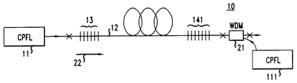
図3は、本発明による例示的なレーザの概略図である。図3のレーザは、図1の従来のレーザに類似しているが、重大な相違点がある。具体的には、図3のレーザは、追加のCPFL111を有し、このCPFLの出力は、WDM21によりラマンファイバ12に結合している。CPFL11の出力(波長1117nm)は、ポンプ反射器(1117nm)とオンレゾナンスであるが、CPFL111の出力(波長1115nm)は、この反射器に関してオフレゾナンスである。オフレゾナンスのポンプ光は、ラマンファイバ12に結合し、グレーティング141および13とほとんど相互作用せずに上流方向に伝搬する。1115nmポンプ光がラマンファイバ12を通ってグレーティングセット13まで伝搬することにより、1115nmポンプ光のストークスシフトが生じ、ストークスシフトした光は下流方向に伝搬する。
【0030】
シリカのラマンスペクトルは比較的広い(図2を参照)ため、1175nmキャビティによって生成される1175nm光が1115nmポンプ光のストークスシフトを誘導する効果は、1117nmポンプ光のストークスシフトとほとんど同程度である。これは、本発明による装置の重要な特徴であると考えられる。
【0031】
図3のグレーティングセット13は、オプションとして、シフトしていない1115nmポンプ光を反射する、中心波長1115nmのポンプ反射器グレーティング(図示せず)を有する。
【0032】
別の従来技術のラマンレーザ(円形トポロジーの)が、前掲のS. V. Chernikov et al.の文献に記載されている。これに記載されているレーザの例は、1.06μmのポンプ入力および1.24μmの出力を有し、1次ストークスシフトが1.12μmで、2次ストークスシフトが1.18μmである。図5は、この文献のFIG.1に対応する。図5において、Ybドープファイバレーザ51は、ラマンレーザに1.06μm入力を供給する。ラマンレーザのリングキャビティは、ポート1〜4を有するWDMカプラと、Geドープシングルモードシリカファイバ(1.2km)52と、高反射器55と、入出力WDMカプラ54とを有する。
【0033】
ポンプ光は、中心波長が1.06および1.24μmのWDMカプラ54を通じてラマンレーザに結合される。ファイバ内のラマン周波数シフトは約440cm-1であるため、1.06μmから1.24μmへの変換は、1.12および1.18μmを中心とする2つの中間ストークス次数を介して3次までのカスケードラマン散乱を通じて行われる。従って、このレーザキャビティにより、ポンプパワーが活性ラマンファイバに結合することが可能となり、1次および2次のストークス次数での共鳴により、高いキャビティ間強度が得られ、損失が最小になる。溶融テーパ状カプラ53は、1.06μmにおけるループ内のポンプ光の約80%をポート1から3へ透過するように設計される。残りの20%は、ループから現れる未変換のポンプパワーとともに、ミラー55によって反射され、部分的に、ラマンファイバ内に逆伝搬方向に結合する。キャビティに入るポンプエネルギーの大部分は1次のラマンストークス次数に変換される。カプラ53は、1.12および1.18μmにおける光に対してポート4からポート3へループ内で最大透過率を有するため、これらの波長における光の85%および95%がそれぞれループ内に残ることになる。
【0034】
高次のストークス次数(約1.3μm)でのレーザ発振を抑圧するため、ファイバベンドタイプのフィルタ(図示せず)をキャビティ内に形成する。ラマンレーザ出力は、最終的に、WDM54を通じてキャビティの外部に結合される。
【0035】
図6は、上記の(円形トポロジーの)図5の従来技術のレーザに類似した、本発明による例示的なラマンレーザの概略図である。図5の従来技術のラマンレーザの特徴に加えて、本発明によるレーザは、光源51とは異なる波長(例えば、1050nm)の出力を有するもう1つのポンプ光源66を有し、溶融ファイバカプラ67は、1050nm(カプラ53に関してオフレゾナンスであるため、85〜95%がポート3からポート4に結合する)のポンプ光をラマンファイバに結合することができるように選択される。
【0036】
前掲論文において、本発明によれば、溶融ファイバカプラは、波長選択素子である。
【0037】
(線形トポロジーの)ラマン増幅器は、(線形トポロジーの)ラマンレーザに類似しており、ポンプ光が1個以上の段を通じてラマンシフトされることにより、その結果得られるポンプ光が、所定の信号光より1ストークスシフトだけ低い波長を有するようにされる。ラマン増幅器の動作中、ポンプ光は、信号光を運ぶシリカ系光ファイバに結合され、信号光が、ポンプ光から信号光へのエネルギー輸送を誘導する。
【0038】
本発明による(円形トポロジーの)ラマン増幅器は、図6に示したのとほぼ同様に構成され、増幅器の動作中、出力光は、信号光を運ぶ光ファイバに結合される。
【0039】
図7は、本発明による例示的な光ファイバ通信システム70の概略図であり、符号71〜76はそれぞれ、送信機、光伝送ファイバ、受信機、EDFA、本発明によるラマンレーザ、および、ラマンレーザ出力光(例えば、1480nm光)を指す。
【0040】
図8は、例示的なラマン増幅器と、関連するコンポーネントを示す概略図である。ファイバレーザ810(通常、Yb3+クラッディングポンプファイバレーザ(CPFL))は、ラマンレーザ82に1117nmポンプ光を供給し、ファイバレーザ811は、1115nmポンプ光を供給する。ラマンレーザは、波長1453nmの出力光を有するように選択される。1453nmポンプ光は、通常のWDM83により信号伝送路に結合され、ある長さ(例えば、約20km)のゲルマノシリケートファイバを通って上流に伝搬する。また、このファイバを通って、1つ以上の信号(波長約1.55μm)が下流方向に伝搬する。信号は、誘導ラマン散乱により通常のように増幅される。増幅された信号は、通常の光アイソレータ85、通常のEDFA86、および通常のバンドパスフィルタ87を通って通常の受信機88へと伝搬する。
【0041】
【発明の効果】
以上述べたごとく、本発明によれば、7個より多くのポンプLED(例えば、14個のポンプLED)からの光でポンピングされるファイバラマンデバイスを有する物品が実現される。
【図面の簡単な説明】
【図1】従来の線形トポロジーのラマンレーザの概略図である。
【図2】ゲルマノシリケートのラマンスペクトルの図である。
【図3】本発明による例示的な線形トポロジーのラマンレーザの概略図である。
【図4】波長の関数として例示的なファイバグレーティングの透過率を示す図である。
【図5】従来の円形トポロジーのラマンレーザの概略図である。
【図6】本発明による円形トポロジーのラマンレーザの概略図である。
【図7】本発明による例示的な光ファイバ通信システムの概略図である。
【図8】例示的なラマン増幅器と、関連するコンポーネントを示す概略図である。
【符号の説明】
10 ファイバラマンレーザ
11 CPFL
111 CPFL
12 ラマンファイバ
13 上流グレーティングセット
14 下流グレーティングセット
15 グレーティング
21 WDM
51 Ybドープファイバレーザ
52 Geドープシングルモードシリカファイバ
53 溶融テーパ状カプラ
54 入出力WDMカプラ
55 高反射器
66 ポンプ光源
67 溶融ファイバカプラ
70 光ファイバ通信システム
71 送信機
72 光伝送ファイバ
73 受信機
74 EDFA
75 ラマンレーザ
76 ラマンレーザ出力光
810 ファイバレーザ
811 ファイバレーザ
82 ラマンレーザ
83 WDM
85 光アイソレータ
86 EDFA
87 バンドパスフィルタ
88 受信機[0001]
BACKGROUND OF THE INVENTION
The present invention relates to an article comprising a fiber optic Raman device (eg, a fiber optic communication system or a light source or amplifier for such a system).
[0002]
[Prior art]
Fiber optic Raman lasers and amplifiers (collectively referred to as “fiber Raman devices”) are known. For example, US Pat. No. 5,323,404 describes a specific example of a first type (linear topology) fiber Raman device having a fiber grating acting as a wavelength selective element.
[0003]
The second type (circular topology) fiber Raman laser is described, for example, in SV Chernikov et al., Electronics Letters , Vol. 34 (7), April 1998, pp. 680-681. In this example, a ring cavity is formed by using a fused fiber coupler as a wavelength selection element.
[0004]
A fiber optic Raman device can be used to provide pump light (eg, at a wavelength of 1480 nm) to an Er-doped fiber amplifier (EDFA) and can be used to amplify signal light (eg, 1310 nm). is there.
[0005]
FIG. 1 is a schematic diagram of a conventional
[0006]
CPFL is known and commercially available (eg, US patent application Ser. No. 08 / 897,195 (filing date: July 21, 1997, inventor: DiGiovanni et al.) And 08 / 999,429). (See filing date: December 29, 1997, inventor: DiGiovanni et al.)). In short, the CPFL has several high power light emitting diodes (eg, InGaAlAs diodes). The output of each LED is coupled to a multimode fiber (e.g., a silica-based fiber having a NA. The fiber is melted in a bundle, for example as described in US patent application Ser. No. 09 / 315,631 (filing date: May 20, 1999, inventor: DiGiovanni et al.). Tapered.
[0007]
At present, it is not easy to form a tapered bundle of more than seven multimode fibers. This limits the number of pump light sources to seven and correspondingly limits the power that can be provided to the utilization means (eg, EDFA).
[0008]
[Problems to be solved by the invention]
Clearly, it would be desirable to be able to provide pump light from more than 7 LEDs to the fiber Raman device. The present invention realizes an article having a fiber Raman device that is pumped with light from more than 7 pump LEDs (eg, 14 pump LEDs).
[0009]
[Definition and explanation of terms]
The terms “light” and “radiation” are used interchangeably herein for the associated electromagnetic radiation (usually infrared light).
[0010]
The optical fiber grating and the fused fiber coupler are collectively referred to herein as a “wavelength selection element”. The fused fiber coupler is often referred to as “WDM”.
[0011]
The “Raman spectrum” of an optical fiber is the scattering intensity as a function of the wavelength difference from the incident light. A shift to a longer wavelength is generally called a Stokes shift. Normally, the Stokes shift is expressed by the reciprocal of centimeter (cm −1 ), but it can also be expressed in wavelength units.
[0012]
The Raman spectrum of germanosilicate glass is relatively broad compared to the wavelength of the pump light and has a marked maximum at a Stokes shift of about 440 cm −1 . FIG. 2 shows a Raman spectrum for pump light of 1427 nm.
[0013]
A wavelength selective element in a Raman device that responds to a given pump light is referred to herein as “on resonance” (resonates) (with respect to the pump light), and an element that does not respond to a given pump light is referred to herein as (pump It is called “off-resonance” (no resonance).
[0014]
The wavelength-selective element “responds” to the pump light provided when the interaction between the element and the light is at or near the maximum, for example, whether the reflectance of the grating is 50% or more of the maximum reflectance of the grating. Alternatively, the pump light enters the wavelength range where the coupling strength of the fiber coupler (WDM) is 50% or more of the maximum coupling strength of the coupler.
[0015]
[Means for Solving the Problems]
In general, the present invention is implemented in articles such as fiber optic communication systems having fiber optic Raman devices suitable for utilizing optical pump power.
[0016]
Raman devices
Having a length of silica-based optical fiber including at least first and second wavelength selective elements arranged to provide one or more optical cavities for Raman shift of light in the optical fiber;
And a first coupler for coupling the pump light having the first wavelength λ 1 from the first pump light source to the optical fiber,
In addition, there is provided means for providing Raman-shifted Raman device output light having a wavelength λ 0 higher than λ 1 to the output light utilization means. Importantly, the fiber Raman device further includes a second coupler for coupling the pump light having the second wavelength λ 2 from the second pump light source to the optical fiber. Here, λ 2 is different from λ 1 and λ 0 > λ 2 , and at least one of the wavelength selection elements is off-resonant with respect to at least one of λ 1 and λ 2 .
[0017]
When the fiber Raman device is a linear topology Raman laser, the first and second wavelength selective elements are typically fiber gratings, and means for providing output light to the output light utilization means is, for example, a relatively low reflectivity output. It is a coupler. When the device is a circular topology Raman laser, the wavelength selection element is usually a fiber coupler (WDM), and the means for providing output light to the output light utilization means also usually has WDM.
[0018]
When the fiber Raman device is a linear topology Raman laser, the wavelength selection element is usually a fiber grating, and the means for providing output light to the output light utilization means is a high reflectivity light for light having a Stokes shift from the signal light. Has a cavity. If the device is a circular topology Raman amplifier, the wavelength selective element is typically WDM, and the means for providing output light to the output light utilization means also typically has WDM.
[0019]
When the Raman device is a linear topology Raman device, | λ 1 −λ 2 | is typically greater than 0.2 nm, and when the Raman device is a circular topology Raman device, | λ 1 −λ 2 | is typically about 3 nm. Greater than.
[0020]
DETAILED DESCRIPTION OF THE INVENTION
In most of the description below, two examples are described. One is a silica based Raman laser (of linear topology), the first pump light (on resonance) is 1117 nm, the second pump light (off resonance) is about 1115 nm, and the Raman laser output is 1480 nm. The other is a Raman laser (with a circular topology), with a fused fiber coupler as the wavelength selection element, the first pump light (on resonance) is 1060 nm, and the second pump light (off resonance) is about 1110 nm. is there. However, it will be appreciated that the present invention is not limited to a specific set of pump wavelengths or a set of wavelength selective elements such as fiber gratings, and suitable pump wavelengths (at least one of which is off-resonance) and All fiber Raman devices with wavelength selective elements are conceivable.
[0021]
FIG. 2 shows a Raman spectrum of a normal silica-based fiber having a germanosilicate core and pumped with 1427 nm pump light. As can be seen from FIG. 2, the maximum scattering intensity is at about 1521 nm, but the high intensity ranges from approximately 1460 to 1550 nm. Considering this relatively broad Raman spectrum, the wavelength selective element in the fiber Raman laser does not need to be selected to produce accurate maximum Raman scattering, and even if it deviates slightly from that value, the decrease in scattering intensity is comparable. Small. As will be appreciated, the spectrum of FIG. 2 is unique for each pump wavelength used.
[0022]
In a conventional fiber Raman laser (of a linear topology), a pump reflector fiber grating having a reflectance of almost 100% at the wavelength of the
[0023]
For the purposes of the present invention, the order in which the gratings are arranged is generally not important. The 1117 nm wavelength pump light is coupled to the Raman fiber and travels downstream to the 1117 nm pump reflector grating where almost all of the remaining 1117 nm light is reflected. The 1117 nm light undergoes Raman scattering, producing 1175 nm light in the 1175 nm optical cavity. Subsequently, 1240 nm light is generated in the 1240 nm optical cavity by Raman scattering of 1175 nm light, and 1480 nm light is output from the Raman laser in the same manner.
[0024]
All of the fiber Bragg gratings in FIG. 1 have a high reflectance (HR: usually 95% or more, preferably 99% or more of the peak reflectance) except for one. The grating 15 (1480 nm) acts as an output coupler and emits 1480 nm output light from the 1480 nm optical cavity. For example, the reflectance of the grating 15 is in the range of 4 to 15% at 1480 nm.
[0025]
Usually, the fiber Bragg grating has bi-directional symmetry. That is, in this device, the response spectrum for light traveling in one direction of the fiber and the response spectrum for light traveling in the opposite direction are the same. Thus, with respect to FIG. 1, when the
[0026]
However, the fiber Bragg grating has a high reflectivity at a first wavelength (eg, 1117 nm) and a low reflectivity (eg, a transmittance of about 98% or more) at a nearby second wavelength (eg, 1115 nm). It is possible to manufacture as follows. FIG. 4 shows the spectrum of an exemplary fiber Bragg grating that can be used to implement the present invention. The grating of FIG. 4 has a center wavelength λ c = 1116.62 nm, a reflectance peak width Δλ = 0.33 nm, and a maximum reflectance higher than 99%.
[0027]
FIG. 4 also shows a grating having high transmittance (and hence low reflectance) in the spectral region on the low wavelength side of the reflectance peak.
[0028]
As will be appreciated, a transmission spectrum of the type shown in FIG. 4 can be easily achieved by conventional means and does not require special manufacturing methods.
[0029]
FIG. 3 is a schematic diagram of an exemplary laser according to the present invention. The laser of FIG. 3 is similar to the conventional laser of FIG. 1 with significant differences. Specifically, the laser of FIG. 3 has an
[0030]
Since the Raman spectrum of silica is relatively wide (see FIG. 2), the effect of the 1175 nm light generated by the 1175 nm cavity inducing the Stokes shift of the 1115 nm pump light is almost the same as the Stokes shift of the 1117 nm pump light. This is considered to be an important feature of the device according to the invention.
[0031]
The grating set 13 of FIG. 3 optionally has a pump reflector grating (not shown) with a central wavelength of 1115 nm that reflects unshifted 1115 nm pump light.
[0032]
Another prior art Raman laser (of circular topology) is described in the above-mentioned SV Chernikov et al. The example laser described therein has a pump input of 1.06 μm and an output of 1.24 μm, a primary Stokes shift of 1.12 μm and a secondary Stokes shift of 1.18 μm. FIG. 5 shows FIG. Corresponding to 1. In FIG. 5, a Yb-doped
[0033]
The pump light is coupled to the Raman laser through the
[0034]
In order to suppress laser oscillation at higher Stokes orders (about 1.3 μm), a fiber bend type filter (not shown) is formed in the cavity. The Raman laser output is finally coupled out of the cavity through the
[0035]
FIG. 6 is a schematic diagram of an exemplary Raman laser according to the present invention, similar to the prior art laser of FIG. 5 (in a circular topology) described above. In addition to the features of the prior art Raman laser of FIG. 5, the laser according to the present invention has another pump
[0036]
In the above paper, according to the present invention, the fused fiber coupler is a wavelength selective element.
[0037]
A Raman amplifier (with a linear topology) is similar to a Raman laser (with a linear topology), and the pump light is Raman-shifted through one or more stages, so that the resulting pump light is less than the predetermined signal light. It is made to have a wavelength lower by one Stokes shift. During operation of the Raman amplifier, the pump light is coupled to a silica-based optical fiber that carries the signal light, and the signal light induces energy transport from the pump light to the signal light.
[0038]
A Raman amplifier (circular topology) according to the present invention is constructed in much the same way as shown in FIG. 6, and during operation of the amplifier, the output light is coupled to an optical fiber carrying signal light.
[0039]
FIG. 7 is a schematic diagram of an exemplary fiber optic communication system 70 according to the present invention, where reference numerals 71-76 respectively denote a transmitter, an optical transmission fiber, a receiver, an EDFA, a Raman laser according to the present invention, and a Raman laser output light. (For example, 1480 nm light).
[0040]
FIG. 8 is a schematic diagram illustrating an exemplary Raman amplifier and associated components. A fiber laser 810 (usually Yb 3+ cladding pump fiber laser (CPFL)) supplies 1117 nm pump light to the
[0041]
【The invention's effect】
As described above, the present invention provides an article having a fiber Raman device that is pumped with light from more than seven pump LEDs (eg, 14 pump LEDs).
[Brief description of the drawings]
FIG. 1 is a schematic view of a Raman laser having a conventional linear topology.
FIG. 2 is a diagram of a Raman spectrum of germanosilicate.
FIG. 3 is a schematic diagram of an exemplary linear topology Raman laser in accordance with the present invention.
FIG. 4 shows the transmittance of an exemplary fiber grating as a function of wavelength.
FIG. 5 is a schematic diagram of a conventional circular topology Raman laser.
FIG. 6 is a schematic diagram of a circular topology Raman laser according to the present invention.
FIG. 7 is a schematic diagram of an exemplary fiber optic communication system in accordance with the present invention.
FIG. 8 is a schematic diagram illustrating an exemplary Raman amplifier and associated components.
[Explanation of symbols]
10
111 CPFL
12
51 Yb-doped
75
85
87
Claims (8)
b)波長λ0のラマンデバイス出力光を生成するために、第1波長λ1のポンプ光(λ 1 <λ 0 )を前記第1の光ファイバブラッググレーティングが配置された前記光ファイバの一端に結合する第1ポンプ光源とを含むファイバラマンデバイスを有する物品において、前記ファイバラマンデバイスはさらに、
c)波長λ0 のラマンデバイス出力光を生成するために、第2波長λ2のポンプ光(λ 2 <λ 0 及びλ 2 ≠λ 1 )を前記第2の光ファイバブラッググレーティングが配置された前記光ファイバの他端に結合する第2ポンプ光源を含み、
前記第1の光ファイバブラッググレーティングは前記第1波長λ 1 に関してオフレゾナンスであり、前記第2の光ファイバブラッググレーティングは前記第2波長λ 2 に関してオフレゾナンスであることを特徴とする、ファイバラマンデバイスを有する物品。a) a length of silica-based optical fiber having at least first and second optical fiber Bragg gratings arranged to provide one or more optical cavities for Raman shift of light within the optical fiber; ,
b) In order to generate Raman device output light having a wavelength λ 0 , pump light (λ 1 <λ 0 ) having a first wavelength λ 1 is applied to one end of the optical fiber on which the first optical fiber Bragg grating is disposed. In an article having a fiber Raman device including a first pump light source for coupling, the fiber Raman device further comprises:
c) The second optical fiber Bragg grating is arranged with the pump light (λ 2 <λ 0 and λ 2 ≠ λ 1 ) of the second wavelength λ 2 to generate the Raman device output light of the wavelength λ 0 includes a second pump light source for coupling to the other end of the optical fiber,
Characterized in that said first optical fiber Bragg grating is off resonance with respect to the first wavelength lambda 1, the second optical fiber Bragg grating is off resonance with respect to the second wavelength lambda 2, the fiber Article having a Raman device.
b)波長λ 0 のラマンデバイス出力光を生成するために、第1波長λ 1 のポンプ光(λ 1 <λ 0 )を前記WDMカプラに結合する第1ポンプ光源を含むファイバラマンデバイスを有する物品において、前記ファイバラマンデバイスはさらに、
c)波長λ 0 のラマンデバイス出力光を生成するために、第2波長λ 2 のポンプ光(λ 2 <λ 0 及びλ 2 ≠λ 1 )を前記シリカ系光ファイバに結合する第2ポンプ光源を含み、
前記WDMカプラは、前記第1波長λ 1 に関してオンレゾナンスであって前記第1波長λ 1 のポンプ光を前記シリカ系光ファイバに結合し、そして、前記WDMカプラは、前記第2波長λ 2 に関してオフレゾナンスであって前記第2波長λ 2 のポンプ光を前記シリカ系光ファイバに結合することを特徴とする、ファイバラマンデバイスを有する物品。 a) a silica-based optical fiber having a length that generates a Raman shift of light having a WDM coupler, wherein the WDM coupler combines one end and the other end of the silica-based optical fiber to form a circular topology; In addition,
b) Article having a fiber Raman device including a first pump light source that couples pump light (λ 1 <λ 0 ) of a first wavelength λ 1 to the WDM coupler to generate Raman device output light of wavelength λ 0 In the fiber Raman device,
c) a second pump light source that couples pump light of the second wavelength λ 2 (λ 2 <λ 0 and λ 2 ≠ λ 1 ) to the silica-based optical fiber to generate Raman device output light of wavelength λ 0 Including
The WDM coupler, wherein the first wavelength lambda pump light of the first wavelength lambda 1 and an on-resonance with respect to 1 bonded to the silica-based optical fiber, and the WDM coupler, with respect to the second wavelength lambda 2 An article having a fiber Raman device, characterized in that it is off-resonance and couples the pump light of the second wavelength λ 2 to the silica-based optical fiber .
Applications Claiming Priority (2)
| Application Number | Priority Date | Filing Date | Title |
|---|---|---|---|
| US09/369,393 US6434172B1 (en) | 1999-08-06 | 1999-08-06 | Article comprising a fiber raman device |
| US09/369393 | 1999-08-06 |
Related Child Applications (1)
| Application Number | Title | Priority Date | Filing Date |
|---|---|---|---|
| JP2008122813A Division JP4559504B2 (en) | 1999-08-06 | 2008-05-09 | Articles having fiber Raman devices |
Publications (2)
| Publication Number | Publication Date |
|---|---|
| JP2001066650A JP2001066650A (en) | 2001-03-16 |
| JP4149641B2 true JP4149641B2 (en) | 2008-09-10 |
Family
ID=23455300
Family Applications (2)
| Application Number | Title | Priority Date | Filing Date |
|---|---|---|---|
| JP2000230391A Expired - Lifetime JP4149641B2 (en) | 1999-08-06 | 2000-07-31 | Articles having fiber Raman devices |
| JP2008122813A Expired - Fee Related JP4559504B2 (en) | 1999-08-06 | 2008-05-09 | Articles having fiber Raman devices |
Family Applications After (1)
| Application Number | Title | Priority Date | Filing Date |
|---|---|---|---|
| JP2008122813A Expired - Fee Related JP4559504B2 (en) | 1999-08-06 | 2008-05-09 | Articles having fiber Raman devices |
Country Status (4)
| Country | Link |
|---|---|
| US (1) | US6434172B1 (en) |
| EP (1) | EP1075062B1 (en) |
| JP (2) | JP4149641B2 (en) |
| DE (1) | DE60024002T2 (en) |
Families Citing this family (30)
| Publication number | Priority date | Publication date | Assignee | Title |
|---|---|---|---|---|
| GB9928474D0 (en) * | 1999-12-03 | 2000-02-02 | Secr Defence Brit | Laser effects and laser devices |
| RU2158458C1 (en) * | 2000-02-08 | 2000-10-27 | Научный центр волоконной оптики при Институте общей физики РАН | Raman fiber laser |
| EP1130702B1 (en) * | 2000-02-29 | 2008-07-23 | Nec Corporation | Method and device for laser amplification |
| JP2002006348A (en) * | 2000-06-21 | 2002-01-09 | Mitsubishi Electric Corp | Optical amplifier |
| US6624927B1 (en) * | 2001-03-14 | 2003-09-23 | Onetta, Inc. | Raman optical amplifiers |
| US6845194B2 (en) * | 2001-06-27 | 2005-01-18 | Furukawa Electric North America Inc. | Optical bandpass filter using long period gratings |
| US20030021302A1 (en) * | 2001-07-18 | 2003-01-30 | Grudinin Anatoly Borisovich | Raman cascade light sources |
| US6839377B2 (en) * | 2001-10-26 | 2005-01-04 | Agere Systems, Inc. | Optoelectronic device having a fiber grating stabilized pump module with increased locking range and a method of manufacture therefor |
| US6646785B2 (en) * | 2002-01-31 | 2003-11-11 | Corning Incorporated | Fiber ring amplifiers and lasers |
| EP1349242A1 (en) * | 2002-03-27 | 2003-10-01 | Alcatel | Raman fiber amplification stage; optical system and method to control the raman amplification stage |
| AU2003289003A1 (en) * | 2002-12-10 | 2004-06-30 | Nikon Corporation | Ultraviolet light source, phototherapy apparatus using ultraviolet light source, and exposure system using ultraviolet light source |
| KR100628472B1 (en) * | 2004-05-24 | 2006-09-26 | 한국과학기술연구원 | Raman or erbium-doped fiber laser sensing probe based on fiber Bragg gratings fabricated with few mode fibers for applications to simultaneous measurement of strain and temperature and long-distance remote sensors |
| US7391561B2 (en) | 2005-07-29 | 2008-06-24 | Aculight Corporation | Fiber- or rod-based optical source featuring a large-core, rare-earth-doped photonic-crystal device for generation of high-power pulsed radiation and method |
| ITMI20051625A1 (en) * | 2005-09-01 | 2007-03-02 | Marconi Comm Spa | OPTICAL AMPLIFIER AND WDM RING NETWORK ALL OPTICAL IN METROPOLITAN CONTEXT WITH IT |
| US7768700B1 (en) | 2006-11-30 | 2010-08-03 | Lockheed Martin Corporation | Method and apparatus for optical gain fiber having segments of differing core sizes |
| US8179594B1 (en) | 2007-06-29 | 2012-05-15 | Lockheed Martin Corporation | Method and apparatus for spectral-beam combining of fanned-in laser beams with chromatic-dispersion compensation using a plurality of diffractive gratings |
| JP4873645B2 (en) * | 2007-08-15 | 2012-02-08 | 新日本製鐵株式会社 | Optical fiber Raman laser device |
| JP5323562B2 (en) * | 2008-03-31 | 2013-10-23 | 古河電気工業株式会社 | Cascade Raman laser |
| US8503840B2 (en) | 2010-08-23 | 2013-08-06 | Lockheed Martin Corporation | Optical-fiber array method and apparatus |
| US8441718B2 (en) * | 2009-11-23 | 2013-05-14 | Lockheed Martin Corporation | Spectrally beam combined laser system and method at eye-safer wavelengths |
| DE102009056058B4 (en) * | 2009-11-25 | 2021-08-12 | Fraunhofer-Gesellschaft zur Förderung der angewandten Forschung e.V. | Device for generating excitation radiation for self-calibrating fiber optic Raman sensors, measuring device for detecting the temperature of a measurement object and Raman sensor arrangement |
| US20110134940A1 (en) * | 2009-12-08 | 2011-06-09 | Schlumberger Technology Corporation | Narrow linewidth brillouin laser |
| DE112011101288T5 (en) | 2010-04-12 | 2013-02-07 | Lockheed Martin Corporation | Beam diagnostic and feedback system and methods for spectrally beam combined lasers |
| IL221918A (en) * | 2012-09-12 | 2016-11-30 | V-Gen Ltd | Optical isolator |
| US9366872B2 (en) | 2014-02-18 | 2016-06-14 | Lockheed Martin Corporation | Apparatus and method for fiber-laser output-beam shaping for spectral beam combination |
| US9575390B2 (en) * | 2015-03-31 | 2017-02-21 | Ipg Photonics Corporation | Higher order seedless raman pumping |
| FR3050289B1 (en) * | 2016-04-13 | 2018-04-06 | Centre National De La Recherche Scientifique - Cnrs - | DEVICE FOR GENERATING A WAVE LENGTH PHOTON BEAM DEFINING A SUBSTANTIALLY CONTINUOUS SUPERCONTINUUM |
| EP3611494A1 (en) * | 2018-08-17 | 2020-02-19 | Koninklijke Philips N.V. | System and method for providing an indication of a person's gum health |
| JP6785901B2 (en) * | 2019-02-21 | 2020-11-18 | 株式会社フジクラ | Filter device, laser device |
| CN112414760B (en) * | 2020-11-24 | 2022-06-21 | 桂林电子科技大学 | Ring fiber core beak-shaped optical fiber tweezers system with stable capturing function |
Family Cites Families (13)
| Publication number | Priority date | Publication date | Assignee | Title |
|---|---|---|---|---|
| US4741587A (en) * | 1986-02-20 | 1988-05-03 | American Telephone And Telegraph Company, At&T Bell Laboratories | Optical communications system and method for the generation of a sequence of optical pulses by means of induced modulational instability |
| US5323404A (en) * | 1993-11-02 | 1994-06-21 | At&T Bell Laboratories | Optical fiber laser or amplifier including high reflectivity gratings |
| US5673280A (en) | 1996-02-12 | 1997-09-30 | Lucent Technologies Inc. | Article comprising low noise optical fiber raman amplifier |
| US5623508A (en) * | 1996-02-12 | 1997-04-22 | Lucent Technologies Inc. | Article comprising a counter-pumped optical fiber raman amplifier |
| US5659644A (en) * | 1996-06-07 | 1997-08-19 | Lucent Technologies Inc. | Fiber light source with multimode fiber coupler |
| JPH1073852A (en) * | 1996-09-02 | 1998-03-17 | Nippon Telegr & Teleph Corp <Ntt> | Optical amplification and transmission system |
| US5923684A (en) * | 1996-09-26 | 1999-07-13 | Lucent Technologies Inc. | Fiber amplifier with multiple pass pumping |
| US6212310B1 (en) * | 1996-10-22 | 2001-04-03 | Sdl, Inc. | High power fiber gain media system achieved through power scaling via multiplexing |
| US5815518A (en) * | 1997-06-06 | 1998-09-29 | Lucent Technologies Inc. | Article comprising a cascaded raman fiber laser |
| US5966480A (en) * | 1998-02-23 | 1999-10-12 | Lucent Technologies Inc. | Article comprising an improved cascaded optical fiber Raman device |
| US6310899B1 (en) * | 1998-04-15 | 2001-10-30 | Lucent Technologies Inc. | Cascaded raman resonator system and apparatus |
| US6163552A (en) * | 1998-08-14 | 2000-12-19 | Lucent Technologies Inc. | Article comprising an optical fiber cascaded Raman resonator |
| RU2158458C1 (en) * | 2000-02-08 | 2000-10-27 | Научный центр волоконной оптики при Институте общей физики РАН | Raman fiber laser |
-
1999
- 1999-08-06 US US09/369,393 patent/US6434172B1/en not_active Expired - Lifetime
-
2000
- 2000-07-24 EP EP00306288A patent/EP1075062B1/en not_active Expired - Lifetime
- 2000-07-24 DE DE60024002T patent/DE60024002T2/en not_active Expired - Lifetime
- 2000-07-31 JP JP2000230391A patent/JP4149641B2/en not_active Expired - Lifetime
-
2008
- 2008-05-09 JP JP2008122813A patent/JP4559504B2/en not_active Expired - Fee Related
Also Published As
| Publication number | Publication date |
|---|---|
| JP4559504B2 (en) | 2010-10-06 |
| EP1075062A2 (en) | 2001-02-07 |
| US6434172B1 (en) | 2002-08-13 |
| JP2008197684A (en) | 2008-08-28 |
| JP2001066650A (en) | 2001-03-16 |
| DE60024002D1 (en) | 2005-12-22 |
| EP1075062B1 (en) | 2005-11-16 |
| DE60024002T2 (en) | 2006-07-13 |
| EP1075062A3 (en) | 2002-06-12 |
Similar Documents
| Publication | Publication Date | Title |
|---|---|---|
| JP4559504B2 (en) | Articles having fiber Raman devices | |
| JP3357291B2 (en) | System with Raman fiber laser | |
| JP2813145B2 (en) | Optical fiber amplification system | |
| JP3247292B2 (en) | Optical communication system | |
| EP1107404B1 (en) | Fibre grating stabilized diode laser | |
| JP3749392B2 (en) | Articles including improved cascaded fiber optic Raman devices | |
| JP2000075150A (en) | Article including cascaded raman resonator of optical fiber | |
| EP1124295A2 (en) | Raman fiber laser | |
| US20020012163A1 (en) | Optical fiber amplifier with oscillating pump energy | |
| EP0867986A2 (en) | Optical fiber laser | |
| JP7060648B2 (en) | Raman amplification light source, Raman amplification light source system, Raman amplifier, Raman amplification system | |
| JP2001267665A (en) | Optical fiber for light amplification and optical fiber amplifier and optical fiber laser oscillator | |
| JP4063908B2 (en) | Light source device, optical amplifier, and optical communication system | |
| CN104718474A (en) | Optical fiber and fiber laser apparatus using same | |
| WO2003007040A2 (en) | Amplification with chalcogenide glass fiber | |
| JP2019216162A (en) | Optical fiber amplifier | |
| JP2007273600A (en) | Optical fiber laser | |
| US20040179797A1 (en) | Multi-wavelength optical fiber | |
| JP4134511B2 (en) | Rare earth element doped optical fiber and optical device using the same | |
| US6721088B2 (en) | Single-source multiple-order raman amplifier for optical transmission systems | |
| JP3905479B2 (en) | Fiber laser equipment | |
| JPH0371115A (en) | Optical circuit for light amplification | |
| JP2003031879A (en) | Optical device, optical fiber used therefor, pulse generator, optical amplifier, and fiber laser | |
| JP3240302B2 (en) | Optical amplifier | |
| CA2469832A1 (en) | Optical amplifier with multiple wavelength pump |
Legal Events
| Date | Code | Title | Description |
|---|---|---|---|
| A131 | Notification of reasons for refusal |
Free format text: JAPANESE INTERMEDIATE CODE: A131 Effective date: 20050613 |
|
| A601 | Written request for extension of time |
Free format text: JAPANESE INTERMEDIATE CODE: A601 Effective date: 20050913 |
|
| A602 | Written permission of extension of time |
Free format text: JAPANESE INTERMEDIATE CODE: A602 Effective date: 20050916 |
|
| A521 | Written amendment |
Free format text: JAPANESE INTERMEDIATE CODE: A523 Effective date: 20051213 |
|
| A02 | Decision of refusal |
Free format text: JAPANESE INTERMEDIATE CODE: A02 Effective date: 20060501 |
|
| A521 | Written amendment |
Free format text: JAPANESE INTERMEDIATE CODE: A523 Effective date: 20060823 |
|
| A521 | Written amendment |
Free format text: JAPANESE INTERMEDIATE CODE: A523 Effective date: 20080509 |
|
| A01 | Written decision to grant a patent or to grant a registration (utility model) |
Free format text: JAPANESE INTERMEDIATE CODE: A01 |
|
| A61 | First payment of annual fees (during grant procedure) |
Free format text: JAPANESE INTERMEDIATE CODE: A61 Effective date: 20080626 |
|
| FPAY | Renewal fee payment (event date is renewal date of database) |
Free format text: PAYMENT UNTIL: 20110704 Year of fee payment: 3 |
|
| R150 | Certificate of patent or registration of utility model |
Ref document number: 4149641 Country of ref document: JP Free format text: JAPANESE INTERMEDIATE CODE: R150 Free format text: JAPANESE INTERMEDIATE CODE: R150 |
|
| FPAY | Renewal fee payment (event date is renewal date of database) |
Free format text: PAYMENT UNTIL: 20120704 Year of fee payment: 4 |
|
| R250 | Receipt of annual fees |
Free format text: JAPANESE INTERMEDIATE CODE: R250 |
|
| FPAY | Renewal fee payment (event date is renewal date of database) |
Free format text: PAYMENT UNTIL: 20120704 Year of fee payment: 4 |
|
| FPAY | Renewal fee payment (event date is renewal date of database) |
Free format text: PAYMENT UNTIL: 20130704 Year of fee payment: 5 |
|
| R250 | Receipt of annual fees |
Free format text: JAPANESE INTERMEDIATE CODE: R250 |
|
| R250 | Receipt of annual fees |
Free format text: JAPANESE INTERMEDIATE CODE: R250 |
|
| R250 | Receipt of annual fees |
Free format text: JAPANESE INTERMEDIATE CODE: R250 |
|
| R250 | Receipt of annual fees |
Free format text: JAPANESE INTERMEDIATE CODE: R250 |
|
| R250 | Receipt of annual fees |
Free format text: JAPANESE INTERMEDIATE CODE: R250 |
|
| R250 | Receipt of annual fees |
Free format text: JAPANESE INTERMEDIATE CODE: R250 |
|
| R250 | Receipt of annual fees |
Free format text: JAPANESE INTERMEDIATE CODE: R250 |
|
| R250 | Receipt of annual fees |
Free format text: JAPANESE INTERMEDIATE CODE: R250 |
|
| R250 | Receipt of annual fees |
Free format text: JAPANESE INTERMEDIATE CODE: R250 |
|
| EXPY | Cancellation because of completion of term |