EP1349242A1 - Raman fiber amplification stage; optical system and method to control the raman amplification stage - Google Patents
Raman fiber amplification stage; optical system and method to control the raman amplification stage Download PDFInfo
- Publication number
- EP1349242A1 EP1349242A1 EP02360105A EP02360105A EP1349242A1 EP 1349242 A1 EP1349242 A1 EP 1349242A1 EP 02360105 A EP02360105 A EP 02360105A EP 02360105 A EP02360105 A EP 02360105A EP 1349242 A1 EP1349242 A1 EP 1349242A1
- Authority
- EP
- European Patent Office
- Prior art keywords
- wavelength
- output
- signal
- optical
- raman
- Prior art date
- Legal status (The legal status is an assumption and is not a legal conclusion. Google has not performed a legal analysis and makes no representation as to the accuracy of the status listed.)
- Withdrawn
Links
Images


Classifications
-
- H—ELECTRICITY
- H01—ELECTRIC ELEMENTS
- H01S—DEVICES USING THE PROCESS OF LIGHT AMPLIFICATION BY STIMULATED EMISSION OF RADIATION [LASER] TO AMPLIFY OR GENERATE LIGHT; DEVICES USING STIMULATED EMISSION OF ELECTROMAGNETIC RADIATION IN WAVE RANGES OTHER THAN OPTICAL
- H01S3/00—Lasers, i.e. devices using stimulated emission of electromagnetic radiation in the infrared, visible or ultraviolet wave range
- H01S3/30—Lasers, i.e. devices using stimulated emission of electromagnetic radiation in the infrared, visible or ultraviolet wave range using scattering effects, e.g. stimulated Brillouin or Raman effects
- H01S3/302—Lasers, i.e. devices using stimulated emission of electromagnetic radiation in the infrared, visible or ultraviolet wave range using scattering effects, e.g. stimulated Brillouin or Raman effects in an optical fibre
-
- H—ELECTRICITY
- H01—ELECTRIC ELEMENTS
- H01S—DEVICES USING THE PROCESS OF LIGHT AMPLIFICATION BY STIMULATED EMISSION OF RADIATION [LASER] TO AMPLIFY OR GENERATE LIGHT; DEVICES USING STIMULATED EMISSION OF ELECTROMAGNETIC RADIATION IN WAVE RANGES OTHER THAN OPTICAL
- H01S3/00—Lasers, i.e. devices using stimulated emission of electromagnetic radiation in the infrared, visible or ultraviolet wave range
- H01S3/05—Construction or shape of optical resonators; Accommodation of active medium therein; Shape of active medium
- H01S3/06—Construction or shape of active medium
- H01S3/063—Waveguide lasers, i.e. whereby the dimensions of the waveguide are of the order of the light wavelength
- H01S3/067—Fibre lasers
- H01S3/0675—Resonators including a grating structure, e.g. distributed Bragg reflectors [DBR] or distributed feedback [DFB] fibre lasers
-
- H—ELECTRICITY
- H01—ELECTRIC ELEMENTS
- H01S—DEVICES USING THE PROCESS OF LIGHT AMPLIFICATION BY STIMULATED EMISSION OF RADIATION [LASER] TO AMPLIFY OR GENERATE LIGHT; DEVICES USING STIMULATED EMISSION OF ELECTROMAGNETIC RADIATION IN WAVE RANGES OTHER THAN OPTICAL
- H01S3/00—Lasers, i.e. devices using stimulated emission of electromagnetic radiation in the infrared, visible or ultraviolet wave range
- H01S3/05—Construction or shape of optical resonators; Accommodation of active medium therein; Shape of active medium
- H01S3/08—Construction or shape of optical resonators or components thereof
- H01S3/08086—Multiple-wavelength emission
-
- H—ELECTRICITY
- H01—ELECTRIC ELEMENTS
- H01S—DEVICES USING THE PROCESS OF LIGHT AMPLIFICATION BY STIMULATED EMISSION OF RADIATION [LASER] TO AMPLIFY OR GENERATE LIGHT; DEVICES USING STIMULATED EMISSION OF ELECTROMAGNETIC RADIATION IN WAVE RANGES OTHER THAN OPTICAL
- H01S3/00—Lasers, i.e. devices using stimulated emission of electromagnetic radiation in the infrared, visible or ultraviolet wave range
- H01S3/10—Controlling the intensity, frequency, phase, polarisation or direction of the emitted radiation, e.g. switching, gating, modulating or demodulating
- H01S3/105—Controlling the intensity, frequency, phase, polarisation or direction of the emitted radiation, e.g. switching, gating, modulating or demodulating by controlling the mutual position or the reflecting properties of the reflectors of the cavity, e.g. by controlling the cavity length
- H01S3/1055—Controlling the intensity, frequency, phase, polarisation or direction of the emitted radiation, e.g. switching, gating, modulating or demodulating by controlling the mutual position or the reflecting properties of the reflectors of the cavity, e.g. by controlling the cavity length one of the reflectors being constituted by a diffraction grating
Definitions
- the present invention belongs to the field of cascaded Raman fiber lasers with an active control mechanism as well as to devices and systems containing such elements.
- Raman amplification is known to be effective to provide a flat gain over a wide signal wavelength band when using several pump wavelengths. Broadband Raman amplification is therefore used to amplify signals over a wide wavelength band, and is thus of particular interest in WDM (Wavelength Division Multiplexing) optical transmission systems.
- WDM Widelength Division Multiplexing
- Cascaded Raman fiber lasers are known per se e.g. from document EP-0 651 479.
- Such lasers comprise a length of optical waveguide, typically silica-based optical fiber, and means for introducing pump radiation of wavelength ⁇ p into the length of optical waveguide.
- the device further comprises n (n ⁇ 2) spaced apart pairs of reflector means that define optical "cavities" for electromagnetic radiation of a predetermined wavelength, the cavities comprising at least a portion of the length of optical waveguide.
- Each reflector has an associated center wavelength ⁇ i of a reflection band, and two reflectors of a given pair have substantially the same center wavelength, such that the reflectors of a given pair define an optical cavity of length L i for radiation of wavelength ⁇ i essentially equal to the center wavelength of the reflectors of the given pair.
- the reflectors have a high reflectivity, typically greater than 95%.
- the pump power can be converted, in a multiplicity of stages, to a power at a desired longer wavelength.
- the wavelength ⁇ i at a given stage is determined by the center wavelength of the relevant pair of reflectors, provided that the center wavelength is chosen such that the wavelength difference ( ⁇ i ) between the preceding stage ( ⁇ i-1 ) and the given stage ( ⁇ i ) is within the Stokes band associated with the optical fiber.
- Such a laser further comprises a low reflectivity reflector for radiation of wavelength ⁇ s on the output side of the device, so that most of the power of wavelength ⁇ s is coupled out of the laser.
- cascaded Raman lasers are based on Raman scattering, which is a non-linear optical process that involves coupling of light propagating through a non-linear medium to vibration modes of the non-linear medium an re-radiation at a different, typically longer wavelength.
- a photon is reflected back and forth in each optical cavity before undergoing Raman scattering that results in a photon of longer wavelength that then passes out of the cavity into the next optical cavity.
- the maximum Raman gain occurs at a frequency shift of 13,2 THz, corresponding to a wavelength shift of about 50 to 100 nm for pump wavelengths between about 1000 and 1500 nm.
- a cascaded multi-wavelength Raman fiber laser differs from a single-wavelength Raman fiber laser as described above in that it has several output wavelengths at the same time. It is based on the idea of splitting the Raman gain between several Stokes wavelengths having similar power levels in order to obtain several output wavelengths at the same time. To do so, the output reflectors of the pairs of reflectors having the desired output wavelengths as center wavelengths have a low reflectivity, so that most of the power of the desired output wavelengths is coupled out of the laser.
- the known cascaded multi-wavelength Raman fiber laser described in the above article is configurable, i.e. the power at each wavelength can be varied by changing the reflectivity of the Bragg gratings used to form the cavity.
- a power control of the individual output channels of such a configurable multi-wavelength Raman fiber laser is not sufficient.
- the outputs of the multi-wavelength Raman fiber laser are used as pump wavelengths for a broadband Raman amplifier for example, it is important that such pump wavelengths have precisely controlled respective powers, namely in order to ensure a similar power level on each output channel. This is not possible with the laser described in the above article.
- the object of the present invention is a cascaded multi-wavelength Raman fiber laser adapted for emitting radiation of several distinct wavelengths with a length of optical fiber having input and output sections, with means for introducing pump radiation of wavelength ⁇ p into said length of optical fiber with at least one pair of spaced-apart reflector means, defining an optical cavity belonging to said optical fiber and with means for deriving a control signal from the output wavelength to adjust the reflectivity of said output reflector means.
- one of the wavelengths of the optical monitor signal is selected by a tunable filter.
- the wavelengths of the optical monitor signal are demultiplexed .
- the parameters for adjusting the reflection means are calculated in a control circuit after opto-electrical conversion. It is possible to adjust wavelength by wavelength in a serial process or to adjust all wavelength in a parallel processing.
- the reflection means are adjusted.
- output reflector means having an adjustable reflectivity at the output wavelengths, it is possible to dynamically adjust the power of the output channels so as to precisely ensure a similar power level on each output channel, which is required when the laser is used as a pump for broadband Raman amplification.
- the power of the output channels also depends from the length of the fiber, the intra-cavity losses and the splicing losses. It is therefore all the more important to use adjustable output reflectors according to the invention as there are many parameters which may influence the output powers.
- the laser according to the present invention allows a dynamic control of the output power.
- the center wavelength of said output reflector means is adjustable. This is allows to "de-couple" the center and output wavelengths of the output reflector means; as the output power of the reflector means is maximum at its center wavelength, shifting the center wavelength of the output reflector means thus allows to adjust the output power.
- adjustment of the center wavelength of said output reflector means can be made by increasing said center wavelength.
- Adjustment of the reflectivity of the output reflectors means may be carried out, according to the invention, by adjusting the center wavelength of the reflection band of said output reflector.
- a preferred solution to reach such a goal is to choose a filter function of the reflector means having a shape which is not a step, and which is close enough to a triangle.
- the laser comprises at least two pairs of reflector means and is adapted for emitting radiation of at least two distinct wavelengths ⁇ s1 , ⁇ s2 .
- the reflector means are Bragg gratings
- this can be done by submitting said Bragg grating to strain (by heating or mechanically) in order to alter its transmission characteristics by e.g. changing its pitch.
- Changing the pitch of the Bragg grating leads to a shift of its center wavelength.
- the reflector means which are not output reflector means are such that the difference between their wavelengths of maximum and minimum reflectivity is less than or equal to 0,5 nm.
- the present invention also relates to an optical fiber communication system comprising a fiber laser (10) which further comprises:
- the invention also relates a method for adjusting the raman fiber amplification stage in a feed back loop.
- Figure 1 schematically depicts an exemplary embodiment of a Raman laser 10.
- Pump radiation of wavelength ⁇ p e.g. 1117 nm, from pump source 11 comprising a Yb 3+ laser is coupled via coupler 12 into a germano-silicate single mode optical fiber 13, and radiations of wavelengths 1440, 1455 and 1487 nm are emitted from the output end of the fiber.
- the fiber 13 has an input section 15 and an output section 16, and comprises in-line refractive index gratings such as Bragg gratings 151 to 159, 161 to 169.
- Gratings 151 and 161, 152 and 162, ... 159 and 169 form matched reflector pairs of e.g. center wavelengths 1170, 1229, 1292, 1364, 1306, 1394, 1440, 1455 and 1487 nm respectively.
- Gratings 151 to 159 belong to input section 15, and gratings 161 to 169 belong to output section 16. All gratings except gratings 161, 162 and 163 desirably have high reflectivity, with substantially more than 98% reflectivity at the center wavelength.
- Reflectivity of a grating is defined as the ratio between the power of the optical wave reflected by the grating to the power of the optical wave entering the grating at a given wavelength.
- the lower the reflectivity at a given wavelength the higher the output power of the reflector (i.e. the power of the wave not reflected by the reflector and thus transmitted by the reflector) at said given wavelength.
- reflectivity is maximum at their center wavelength.
- Pairs 151-161, 152-162 and 153-163 of gratings have respective initial center wavelengths equal to the output wavelengths of laser 10.
- the reflectivity of Bragg gratings 161, 162 and 163 at their center wavelength is lower than that of the respective corresponding gratings 151, 152 and 153. It is e.g. in the order of 20%, in order to emit the output wavelength out of the laser.
- an optional grating 17 can be used, having a center wavelength equal to ⁇ p . It serves as pump reflector.
- each of the Bragg gratings 161, 162 and 163, called output Bragg gratings is adjustable at the output wavelengths. To this end, it has been chosen to adjust the center wavelength of Bragg gratings 161, 162 and 163.
- the reflectivity of this grating at the output wavelength is decreased as compared to its initial value.
- the initial value of the reflectivity is the one for which the center wavelength of said output grating is equal to, or even preferably lower than the center wavelength of the corresponding input grating, which is in turn equal to an output wavelength of the laser.
- ⁇ Bragg ⁇ /2.n eff where n eff is the refractive index of the fiber.
- the advantage of the use of such means lies in the fact that the shift in center wavelength is proportional to the stretching of the Bragg grating, so that there is a linear relationship between the reflectivity of the Bragg grating and the output control voltage of the piezoelectric means.
- the invention is not limited to an output of three different wavelength. Also solutions with more than three, for example six or more are realized with the inventional device.
- Figure 2 shows a first embodiment for deriving the control parameters in a feed back loop.
- a tap coupler 20 is connected to the output line of the Raman amplifying stage 10.
- the tap coupler 10 is connected with an Fabry Perot filter 21 and a photodiode 23.
- the electrical output of the photodiode is linked to a control circuit 24.
- the control circuit has connections to the adjustment means 181, 182, 183 of the output reflection means 161, 162, 163.
- the tap coupler 10 branches about 1 percent of the output signal as optical monitor signal in the feed back loop.
- the optical monitor signal is a mixture of all Raman amplification stage wavelengths in our example of 1480, 1455 and 1440 nm .
- This wavelength mix is fed through a tunable Fabry Perot filter. With this filter 21 one of the three wavelength is selected by tuning the spectral range of the filter.
- a Fabry Perot filter can be tuned by changing the optical distance of the cavity.
- the Fabry Perot filter can be replaced by all other kind of filters for selecting one of the wavelengths of the mix.
- the resulting one wavelength is measured with the photodiode 23.
- the electrical signal is fed into the control circuit.
- the electrical photodiode voltage signal is compared with a predefined threshold value for the electrical voltage.
- This predefined threshold is fixed for a fixed output power of the Raman amplifying stage.
- the user wants to run the Raman amplifying stage with two of the possible three wavelengths 1455 nm and 1440 nm. Than the cavity for the 1480 nm line must be detuned. To adjust the Raman amplifying stage you have to start with the measurement for the 1480 nm wavelength.
- the Fabry Perot filter which is in a first step shifted to select the 1480 nm wavelength. The result is a measurement of the output power of the 1480 nm line.
- the threshold for this power is about zero and the control circuit generate the parameter to adjust the adjusting mean 183.
- the parameter has the form of an electrical signal which depends from the way the adjustment of the reflection mean is realized. For example a piezo element put some strain on a fiber Bragg grating. The electrical signal for the piezo element must be high to apply a high stain to the fiber and to obtain a high detuning factor.
- the control circuit applies a fixed high electrical signal value to obtain the detuning.
- the control unit applies signals in several steps, waiting for a new measurement of the optical monitoring signal and adjusting the reflection mean step by step.
- the control circuit has to monitor wavelength per wavelength and to adapt the adjusting means in a serial way.
- FIG. 3 shows a second embodiment of the invention.
- a tap coupler 20 is connected to the output line of the Raman amplifying stage 10.
- the output of the tap coupler 10 is linked to a demultiplexing stage 29.
- This stage consists of drop filters 25,26,27 for each of the Raman wavelengths and taps to drop the single reflected wavelengths.
- the single taps are connected to single photodiodes 231, 232, 233 which have separate connections to the control circuit 24.
- the control circuit therefore receives the signals of the photodiodes parallel and can parallel process the signals to derive at least one parameter for adjusting the reflectivity of the reflection means.
- This demultiplexing stage the parallel monitoring of all three Raman wavelengths is possible.
- the electrical signals for all three lines are measured and the control circuit can adapt three adjusting means in parallel.
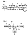
- Figure 4 schematically depicts an optical system 100 according to the invention, incorporating a laser as laser 10 of Figure 1.
- Optical system 100 is a Raman pre-amplified optical fiber communication system comprising:
- Signal radiation 103 (e.g. of wavelength 1550 nm) is coupled into conventional transmission fiber 104 and transmitted there through to the receiver means 102.
- Pump radiations 106 for the distributed Raman amplification is provided by laser 10 according to the invention, coupled into the transmission fiber 104 by conventional WDM 107.
- the Raman laser 10 provides radiations of wavelengths 1440, 1455 and 1487 nm suitable for pumping of the transmission fiber 104 such that the signal radiation 103 is amplified.
- an optical cavity can be formed by coupling the length of optical fiber to planar waveguide reflectors.
- the invention applies as well to WDM transmission systems using Raman pre-amplification with Erbium-doped fiber amplifiers (EDFAs) as to WDM transmission systems using Raman amplification alone.
- EDFAs Erbium-doped fiber amplifiers
- the invention can also be applied for pumping a Dispersion Compensation Fiber (DCF) instead of a line fiber.
- DCF Dispersion Compensation Fiber
Landscapes
- Physics & Mathematics (AREA)
- Electromagnetism (AREA)
- Engineering & Computer Science (AREA)
- Plasma & Fusion (AREA)
- Optics & Photonics (AREA)
- Optical Modulation, Optical Deflection, Nonlinear Optics, Optical Demodulation, Optical Logic Elements (AREA)
- Lasers (AREA)
Abstract
The present invention relates to a cascaded multi-wavelength Raman fiber
amplification stage with a length of optical fiber having input (15) and output
(16) sections, pump laser means (11) for introducing pump radiation of
wavelength λp into said length of optical fiber (13), at least two pairs of
reflector means (151,161;...;159, 169), spaced-apart the length of optical
fiber (13), at least one of said pairs of reflector means has an output reflector
mean (161, 162, 163), with a reflectivity lower than 100% and a feed back
loop with: a tap coupler (20) for deriving a low percentage of the optical
output signal as a optical monitor signal (28), at least one wavelength
selecting element (21, 25,26, 27) for the optical monitor signal (28),
at least one opto-electrical converter (23, 231,232,233) generating a
electrical signal and a control circuit (27) for the electrical signal connected to
adjustment means (181, 182, 183) adjusting the reflectivity of the output
reflector means( 161, 162, 163).
Description
The present invention belongs to the field of cascaded Raman fiber
lasers with an active control mechanism as well as to devices and systems
containing such elements.
Raman amplification is known to be effective to provide a flat gain
over a wide signal wavelength band when using several pump wavelengths.
Broadband Raman amplification is therefore used to amplify signals over a
wide wavelength band, and is thus of particular interest in WDM (Wavelength
Division Multiplexing) optical transmission systems.
In order to provide the necessary pump wavelengths for the Raman
amplification to be efficient (i.e. for the gain to be substantially flat), it is
known to use a cascaded Raman laser having several output channels. The
article "A high-efficiency power-stable three-wavelength configurable Raman
fiber laser", Mermelstein et al., Paper PD3, OFC 2001 discloses a WDM
system using a multi-wavelength cascaded Raman fiber laser to provide pump
wavelengths of 1427, 1455 and 1480 nm to a broadband Raman amplifier.
Cascaded Raman fiber lasers are known per se e.g. from document
EP-0 651 479.
Such lasers comprise a length of optical waveguide, typically
silica-based optical fiber, and means for introducing pump radiation of
wavelength λp into the length of optical waveguide. The device further
comprises n (n ≥ 2) spaced apart pairs of reflector means that define optical
"cavities" for electromagnetic radiation of a predetermined wavelength, the
cavities comprising at least a portion of the length of optical waveguide. Each
reflector has an associated center wavelength λi of a reflection band, and two
reflectors of a given pair have substantially the same center wavelength, such
that the reflectors of a given pair define an optical cavity of length Li for
radiation of wavelength λi essentially equal to the center wavelength of the
reflectors of the given pair. With Δλi (i=1, ..., n) being a length within the
appropriate Stokes band associated with the fiber, λi = λi-1 + Δλi (λ0 = λp).
The reflectors have a high reflectivity, typically greater than 95%.
Therefore, the pump power can be converted, in a multiplicity of
stages, to a power at a desired longer wavelength. The wavelength λi at a
given stage is determined by the center wavelength of the relevant pair of
reflectors, provided that the center wavelength is chosen such that the
wavelength difference (Δλi) between the preceding stage (λi-1) and the given
stage (λi) is within the Stokes band associated with the optical fiber. Such a
laser further comprises a low reflectivity reflector for radiation of wavelength λs
on the output side of the device, so that most of the power of wavelength λs is
coupled out of the laser.
Thus, cascaded Raman lasers are based on Raman scattering, which
is a non-linear optical process that involves coupling of light propagating
through a non-linear medium to vibration modes of the non-linear medium
an re-radiation at a different, typically longer wavelength. A photon is
reflected back and forth in each optical cavity before undergoing Raman
scattering that results in a photon of longer wavelength that then passes out of
the cavity into the next optical cavity.
When a silica-based optical fiber is used as the non-linear medium,
the maximum Raman gain occurs at a frequency shift of 13,2 THz,
corresponding to a wavelength shift of about 50 to 100 nm for pump
wavelengths between about 1000 and 1500 nm.
A cascaded multi-wavelength Raman fiber laser differs from a
single-wavelength Raman fiber laser as described above in that it has several
output wavelengths at the same time. It is based on the idea of splitting the
Raman gain between several Stokes wavelengths having similar power levels
in order to obtain several output wavelengths at the same time. To do so, the
output reflectors of the pairs of reflectors having the desired output
wavelengths as center wavelengths have a low reflectivity, so that most of the
power of the desired output wavelengths is coupled out of the laser.
The known cascaded multi-wavelength Raman fiber laser described in
the above article is configurable, i.e. the power at each wavelength can be
varied by changing the reflectivity of the Bragg gratings used to form the
cavity. However, a power control of the individual output channels of such a
configurable multi-wavelength Raman fiber laser is not sufficient.
Indeed, when the outputs of the multi-wavelength Raman fiber laser
are used as pump wavelengths for a broadband Raman amplifier for
example, it is important that such pump wavelengths have precisely controlled
respective powers, namely in order to ensure a similar power level on each
output channel. This is not possible with the laser described in the above
article.
Besides, it is also desirable to be able to select the required number of
output wavelengths; in other words, it is desired to be able to use the three-wavelength
Raman fiber laser described in the above article as a
two-wavelength laser, or even as a single-wavelength laser.
It is therefore a goal of the present invention to provide a multi-wavelength cascaded Raman fiber laser having precisely controllable output power on at least some output channels, and also being suitable for use with less output wavelengths than the maximum possible output wavelengths.
It is therefore a goal of the present invention to provide a multi-wavelength cascaded Raman fiber laser having precisely controllable output power on at least some output channels, and also being suitable for use with less output wavelengths than the maximum possible output wavelengths.
To this end, the object of the present invention is a cascaded
multi-wavelength Raman fiber laser adapted for emitting radiation of several
distinct wavelengths with a length of optical fiber having input and output
sections, with means for introducing pump radiation of wavelength λp into
said length of optical fiber with at least one pair of spaced-apart reflector
means, defining an optical cavity belonging to said optical fiber and
with means for deriving a control signal from the output wavelength to adjust
the reflectivity of said output reflector means.
In one preferred embodiment one of the wavelengths of the optical monitor signal is selected by a tunable filter. In another preferred embodiment the wavelengths of the optical monitor signal are demultiplexed .The parameters for adjusting the reflection means are calculated in a control circuit after opto-electrical conversion.
It is possible to adjust wavelength by wavelength in a serial process or to adjust all wavelength in a parallel processing.
With this parameters the reflection means are adjusted. By choosing
output reflector means having an adjustable reflectivity at the output
wavelengths, it is possible to dynamically adjust the power of the output
channels so as to precisely ensure a similar power level on each output
channel, which is required when the laser is used as a pump for broadband
Raman amplification.
Therefore, precise values of the reflectivity of each output reflector
means are obtained which allows equalization of the power of the output
channels.
In addition, it has been found that the power of the output channels
also depends from the length of the fiber, the intra-cavity losses and the
splicing losses. It is therefore all the more important to use adjustable output
reflectors according to the invention as there are many parameters which may
influence the output powers. The laser according to the present invention
allows a dynamic control of the output power.
Preferably, the center wavelength of said output reflector means is
adjustable. This is allows to "de-couple" the center and output wavelengths of
the output reflector means; as the output power of the reflector means is
maximum at its center wavelength, shifting the center wavelength of the output
reflector means thus allows to adjust the output power.
In this context, adjustment of the center wavelength of said output
reflector means can be made by increasing said center wavelength.
Adjustment of the reflectivity of the output reflectors means may be
carried out, according to the invention, by adjusting the center wavelength of
the reflection band of said output reflector. A preferred solution to reach such
a goal is to choose a filter function of the reflector means having a shape
which is not a step, and which is close enough to a triangle.
Indeed, in such a case, it is possible to gradually change the output
power, which allows the maximum flexibility.
In a preferred embodiment for WDM applications, the laser comprises
at least two pairs of reflector means and is adapted for emitting radiation of at
least two distinct wavelengths λs1, λs2.
When the reflector means are Bragg gratings, this can be done by
submitting said Bragg grating to strain (by heating or mechanically) in order to
alter its transmission characteristics by e.g. changing its pitch. Changing the
pitch of the Bragg grating leads to a shift of its center wavelength. In such a
case, the reflector means which are not output reflector means are such that
the difference between their wavelengths of maximum and minimum
reflectivity is less than or equal to 0,5 nm.
The present invention also relates to an optical fiber communication system comprising a fiber laser (10) which further comprises:
The present invention also relates to an optical fiber communication system comprising a fiber laser (10) which further comprises:
- transmitter means (101) that comprise means for generating a signal radiation (103) of wavelength λsignal
- receiver means (102) spaced apart from said transmitter means (101) that comprise means for detecting the signal radiation (103) at λsignal,
- optical fiber transmission means (104) that connect said transmitter (101) and receiver (102) means
- means (107) for coupling the output radiation (106) of wavelength λs1 of said Raman laser (10) into said optical fiber transmission means (104).
The invention also relates a method for adjusting the raman fiber
amplification stage in a feed back loop.
These and other objects of the present invention will be appear more
clearly from the following description of a preferred embodiment of the
present invention, given by way of example with respect to the accompanying
drawings.
In the drawings:
- Figure 1 schematically depicts a cascaded Raman fiber laser according to prior art
- Figure 2 shows a first control mechanism
- Figure 3 illustrate schematically a second control mechanism
- Figure 4 shows a optical transmission system
In the figures, common elements or elements having the same
function are identified by the same reference numerals.
Figure 1 schematically depicts an exemplary embodiment of a Raman
laser 10. Pump radiation of wavelength λp, e.g. 1117 nm, from pump source
11 comprising a Yb3+ laser is coupled via coupler 12 into a germano-silicate
single mode optical fiber 13, and radiations of wavelengths 1440, 1455 and
1487 nm are emitted from the output end of the fiber.
The fiber 13 has an input section 15 and an output section 16, and
comprises in-line refractive index gratings such as Bragg gratings 151 to 159,
161 to 169. Gratings 151 and 161, 152 and 162, ... 159 and 169 form
matched reflector pairs of e.g. center wavelengths 1170, 1229, 1292, 1364,
1306, 1394, 1440, 1455 and 1487 nm respectively. Gratings 151 to 159
belong to input section 15, and gratings 161 to 169 belong to output section
16. All gratings except gratings 161, 162 and 163 desirably have high
reflectivity, with substantially more than 98% reflectivity at the center
wavelength.
Reflectivity of a grating (or of any reflector means) is defined as the
ratio between the power of the optical wave reflected by the grating to the
power of the optical wave entering the grating at a given wavelength. Hence,
the lower the reflectivity at a given wavelength, the higher the output power of
the reflector (i.e. the power of the wave not reflected by the reflector and thus
transmitted by the reflector) at said given wavelength. For Bragg gratings,
reflectivity is maximum at their center wavelength.
Pairs 151-161, 152-162 and 153-163 of gratings have respective
initial center wavelengths equal to the output wavelengths of laser 10. The
reflectivity of Bragg gratings 161, 162 and 163 at their center wavelength is
lower than that of the respective corresponding gratings 151, 152 and 153. It
is e.g. in the order of 20%, in order to emit the output wavelength out of the
laser.
In addition to the gratings 151 to 159 and 161 to 169, an optional
grating 17 can be used, having a center wavelength equal to λp. It serves as
pump reflector.
The reflectivity of each of the Bragg gratings 161, 162 and 163,
called output Bragg gratings, is adjustable at the output wavelengths. To this
end, it has been chosen to adjust the center wavelength of Bragg gratings
161, 162 and 163.
Indeed, if the center wavelength of an output Bragg grating is shifted,
the reflectivity of this grating at the output wavelength is decreased as
compared to its initial value. The initial value of the reflectivity is the one for
which the center wavelength of said output grating is equal to, or even
preferably lower than the center wavelength of the corresponding input
grating, which is in turn equal to an output wavelength of the laser.
By selecting an appropriate profile of the reflectivity vs. wavelength
function of the output Bragg gratings, it is then possible to perform simple and
accurate adjustments of the center wavelength of the output Bragg gratings.
There exist solutions well known to the man skilled in the art to shift
the center wavelength of a Bragg grating.
This may be done by modifying the pitch of the grating, e.g. by
heating the grating with Peltier elements. Thermal expansion of the fiber under
heat increases the pitch Λ of the grating and thus the center wavelength λBragg
according to the following relationship:
λBragg = Λ/2.neff
where neff is the refractive index of the fiber.
Another possible solution is to stretch the grating with an adapted
mechanical system. Such systems are described e.g. in the article "Chirping
optical fiber Bragg gratings using tapered-thickness piezoelectric ceramic", M.
Pacheco et al., Electron. Letters, vol. 34, pp. 2348-2350, 1998. The article
"Dispersion variable fiber grating using a piezoelectric stack", M.M. Ohn et
al., Electron. Letters, vol. 32, pp. 2000-2001, 1996 also describes means for
stretching Bragg gratings.
The advantage of the use of such means lies in the fact that the shift in
center wavelength is proportional to the stretching of the Bragg grating, so
that there is a linear relationship between the reflectivity of the Bragg grating
and the output control voltage of the piezoelectric means.
The invention is not limited to an output of three different wavelength.
Also solutions with more than three, for example six or more are realized with
the inventional device.
Figure 2 shows a first embodiment for deriving the control parameters
in a feed back loop.
A tap coupler 20 is connected to the output line of the Raman
amplifying stage 10. The tap coupler 10 is connected with an Fabry Perot filter
21 and a photodiode 23. The electrical output of the photodiode is linked to a
control circuit 24. The control circuit has connections to the adjustment means
181, 182, 183 of the output reflection means 161, 162, 163.
The tap coupler 10 branches about 1 percent of the output signal as
optical monitor signal in the feed back loop. The optical monitor signal is a
mixture of all Raman amplification stage wavelengths in our example of 1480,
1455 and 1440 nm . This wavelength mix is fed through a tunable Fabry
Perot filter. With this filter 21 one of the three wavelength is selected by tuning
the spectral range of the filter. A Fabry Perot filter can be tuned by changing
the optical distance of the cavity. The Fabry Perot filter can be replaced by all
other kind of filters for selecting one of the wavelengths of the mix. The
resulting one wavelength is measured with the photodiode 23. The electrical
signal is fed into the control circuit. There the electrical photodiode voltage
signal is compared with a predefined threshold value for the electrical voltage.
This predefined threshold is fixed for a fixed output power of the Raman
amplifying stage.
For example: The user wants to run the Raman amplifying stage with two of the possible threewavelengths 1455 nm and 1440 nm. Than the cavity for the
1480 nm line must be detuned. To adjust the Raman amplifying stage you
have to start with the measurement for the 1480 nm wavelength. The Fabry
Perot filter which is in a first step shifted to select the 1480 nm wavelength.
The result is a measurement of the output power of the 1480 nm line. The
threshold for this power is about zero and the control circuit generate the
parameter to adjust the adjusting mean 183. The parameter has the form of
an electrical signal which depends from the way the adjustment of the
reflection mean is realized. For example a piezo element put some strain on a
fiber Bragg grating. The electrical signal for the piezo element must be high to
apply a high stain to the fiber and to obtain a high detuning factor.
The control circuit applies a fixed high electrical signal value to obtain the detuning. In another embodiment the control unit applies signals in several steps, waiting for a new measurement of the optical monitoring signal and adjusting the reflection mean step by step. For an adaptation of all Raman lines the control circuit has to monitor wavelength per wavelength and to adapt the adjusting means in a serial way.
For example: The user wants to run the Raman amplifying stage with two of the possible three
The control circuit applies a fixed high electrical signal value to obtain the detuning. In another embodiment the control unit applies signals in several steps, waiting for a new measurement of the optical monitoring signal and adjusting the reflection mean step by step. For an adaptation of all Raman lines the control circuit has to monitor wavelength per wavelength and to adapt the adjusting means in a serial way.
Figure 3 shows a second embodiment of the invention. A tap coupler 20 is
connected to the output line of the Raman amplifying stage 10. The output of
the tap coupler 10 is linked to a demultiplexing stage 29. This stage consists
of drop filters 25,26,27 for each of the Raman wavelengths and taps to drop
the single reflected wavelengths. The single taps are connected to single
photodiodes 231, 232, 233 which have separate connections to the control
circuit 24. The control circuit therefore receives the signals of the photodiodes
parallel and can parallel process the signals to derive at least one parameter
for adjusting the reflectivity of the reflection means. With this demultiplexing
stage the parallel monitoring of all three Raman wavelengths is possible. The
electrical signals for all three lines are measured and the control circuit can
adapt three adjusting means in parallel.
Figure 4 schematically depicts an optical system 100 according to the
invention, incorporating a laser as laser 10 of Figure 1.
- transmitter means 101
- receiver means 102 spaced apart from transmitter means 101.
Signal radiation 103 (e.g. of wavelength 1550 nm) is coupled into
conventional transmission fiber 104 and transmitted there through to the
receiver means 102. Pump radiations 106 for the distributed Raman
amplification is provided by laser 10 according to the invention, coupled into
the transmission fiber 104 by conventional WDM 107. The Raman laser 10
provides radiations of wavelengths 1440, 1455 and 1487 nm suitable for
pumping of the transmission fiber 104 such that the signal radiation 103 is
amplified.
For clarity sake, only one WDM multiplexer has been shown on Figure
4, but it is to be understood that several such means are disposed along the
length of transmission fiber 104.
Of course, the present invention is not limited to the embodiments
described above.
Although in-line refractive index fiber gratings are currently preferred
reflector means, use of other reflector means is also contemplated. For
instance, an optical cavity can be formed by coupling the length of optical
fiber to planar waveguide reflectors.
In addition, ordering of the reflector means according to the teachings
of US-5 815 518 can also be applied to lasers of the present invention.
At last, the invention applies as well to WDM transmission systems
using Raman pre-amplification with Erbium-doped fiber amplifiers (EDFAs) as
to WDM transmission systems using Raman amplification alone.
The invention can also be applied for pumping a Dispersion
Compensation Fiber (DCF) instead of a line fiber.
Claims (8)
- A cascaded multi-wavelength Raman fiber amplification stage comprising:a length of optical fiber (13) having input (15) and output (16) sectionspump laser means (11) for introducing pump radiation of wavelength λp into said length of optical fiber (13)at least two pairs of reflector means (151,161;...;159, 169), spaced-apart the length of optical fiber (13)at least two of said pairs of reflector means has an output reflector mean (161, 162, 163), with a reflectivity lower than 100%a feed back loop with:a tap coupler (20) for deriving a low percentage of the optical output signal as a optical monitor signal (28)at least one wavelength selecting element (21, 25,26, 27) for the optical monitor signal (28)at least one opto-electrical converter (23, 231,232,233) generating a electrical signala control circuit (27) for the electrical signal connected to adjustment means (181, 182, 183) adjusting the reflectivity of the output reflector means( 161, 162, 163).
- A cascaded multi-wavelength Raman fiber amplification stage according to claim 1 where the tap coupler (20) is connected to a tunable wavelength selective filter (23) selecting one wavelength and to a photodiode (23).
- A cascaded multi-wavelength Raman fiber amplification stage according to claim 2 where the wavelength selective filter is a tunable Fabry Perot filter.
- A cascaded multi-wavelength Raman fiber amplification stage according to claim 1 where the feed back loop comprises a wavelength demultiplexing filter (29) with photodiodes (231,232,233) for the simultaneously demultiplexed wavelengths.
- A cascaded multi-wavelength Raman fiber amplification stage according to claim 1 wherein that said reflector means are fiber Bragg gratings.
- A cascaded multi-wavelength Raman fiber amplification stage according to claim 1 wherein shifting of the center wavelength is obtained by heating or straining said Bragg grating.
- Optical fiber communication system comprising a fiber laser (10) according to claim 1 which further comprises:transmitter means (101) that comprise means for generating a signal radiation (103) of wavelength λsignalreceiver means (102) spaced apart from said transmitter means (101) that comprise means for detecting the signal radiation (103) at λsignal,optical fiber transmission means (104) that connect said transmitter (101) and receiver (102) meansmeans (107) for coupling the output radiation (106) of wavelength λs1 of said Raman laser (10) into said optical fiber transmission means (104).
- Method for controlling a cascaded multi-wavelength Raman fiber amplification stage using a feed back looptaping an optical monitoring signalselecting at least one wavelength of the optical monitor signalconverting the optical monitor signal of at least one wavelength to an electrical control signalderiving control parameters in a control circuitadjusting output reflection means according to the said parameters.
Priority Applications (2)
| Application Number | Priority Date | Filing Date | Title |
|---|---|---|---|
| EP02360105A EP1349242A1 (en) | 2002-03-27 | 2002-03-27 | Raman fiber amplification stage; optical system and method to control the raman amplification stage |
| US10/359,150 US20030184848A1 (en) | 2002-03-27 | 2003-02-06 | Raman fiber amplification stage, optical system and method to control the Raman amplification |
Applications Claiming Priority (1)
| Application Number | Priority Date | Filing Date | Title |
|---|---|---|---|
| EP02360105A EP1349242A1 (en) | 2002-03-27 | 2002-03-27 | Raman fiber amplification stage; optical system and method to control the raman amplification stage |
Publications (1)
| Publication Number | Publication Date |
|---|---|
| EP1349242A1 true EP1349242A1 (en) | 2003-10-01 |
Family
ID=27798943
Family Applications (1)
| Application Number | Title | Priority Date | Filing Date |
|---|---|---|---|
| EP02360105A Withdrawn EP1349242A1 (en) | 2002-03-27 | 2002-03-27 | Raman fiber amplification stage; optical system and method to control the raman amplification stage |
Country Status (2)
| Country | Link |
|---|---|
| US (1) | US20030184848A1 (en) |
| EP (1) | EP1349242A1 (en) |
Cited By (2)
| Publication number | Priority date | Publication date | Assignee | Title |
|---|---|---|---|---|
| EP1523076A1 (en) * | 2003-10-10 | 2005-04-13 | Alcatel | Raman laser with a simplified structure of wavelength selectors |
| US7340136B2 (en) * | 2001-07-02 | 2008-03-04 | Ocg Technology Licensing, Llc | Multi-wavelength optical fiber |
Families Citing this family (1)
| Publication number | Priority date | Publication date | Assignee | Title |
|---|---|---|---|---|
| GB0129717D0 (en) * | 2001-12-12 | 2002-01-30 | Marconi Comm Ltd | A method and an apparatus for signal transmission |
Citations (3)
| Publication number | Priority date | Publication date | Assignee | Title |
|---|---|---|---|---|
| US5691999A (en) * | 1994-09-30 | 1997-11-25 | United Technologies Corporation | Compression-tuned fiber laser |
| WO2000004613A1 (en) * | 1998-07-14 | 2000-01-27 | Korea Advanced Institute Of Science And Technology | Optical amplifier with actively controlled spectral gain and fiber light source with desired output spectrum |
| EP0984532A1 (en) * | 1998-08-14 | 2000-03-08 | Lucent Technologies Inc. | Article comprising an optical fiber cascaded raman resonator |
Family Cites Families (19)
| Publication number | Priority date | Publication date | Assignee | Title |
|---|---|---|---|---|
| US5022730A (en) * | 1989-12-12 | 1991-06-11 | At&T Bell Laboratories | Wavelength tunable optical filter |
| US5323404A (en) * | 1993-11-02 | 1994-06-21 | At&T Bell Laboratories | Optical fiber laser or amplifier including high reflectivity gratings |
| US5815518A (en) * | 1997-06-06 | 1998-09-29 | Lucent Technologies Inc. | Article comprising a cascaded raman fiber laser |
| US5982791A (en) * | 1998-01-14 | 1999-11-09 | Hewlett-Packard Company | Wavelength tracking in adjustable optical systems |
| US5966480A (en) * | 1998-02-23 | 1999-10-12 | Lucent Technologies Inc. | Article comprising an improved cascaded optical fiber Raman device |
| US6310899B1 (en) * | 1998-04-15 | 2001-10-30 | Lucent Technologies Inc. | Cascaded raman resonator system and apparatus |
| US6567430B1 (en) * | 1998-09-21 | 2003-05-20 | Xtera Communications, Inc. | Raman oscillator including an intracavity filter and amplifiers utilizing same |
| US6208773B1 (en) * | 1999-02-18 | 2001-03-27 | Trw Inc. | Addressable, semiconductor adaptable Bragg gratings (ASABG) |
| US6434172B1 (en) * | 1999-08-06 | 2002-08-13 | Fitel Usa Corp. | Article comprising a fiber raman device |
| US6407855B1 (en) * | 1999-10-29 | 2002-06-18 | Sdl, Inc. | Multiple wavelength optical sources |
| JP2002040495A (en) * | 2000-07-21 | 2002-02-06 | Sumitomo Electric Ind Ltd | Raman amplifier |
| JP4821037B2 (en) * | 2000-08-25 | 2011-11-24 | 富士通株式会社 | Optical amplifier and Raman pump light source using Raman amplification |
| US6594288B1 (en) * | 2000-11-06 | 2003-07-15 | Cidra Corporation | Tunable raman laser and amplifier |
| US6807338B2 (en) * | 2001-03-12 | 2004-10-19 | Fitel Usa Corp. | Multiwavelength cascaded raman resonator |
| US6624927B1 (en) * | 2001-03-14 | 2003-09-23 | Onetta, Inc. | Raman optical amplifiers |
| US6529316B1 (en) * | 2001-05-03 | 2003-03-04 | Onetta, Inc. | Optical network equipment with optical channel monitor and dynamic spectral filter alarms |
| US6768577B2 (en) * | 2002-03-15 | 2004-07-27 | Fitel Usa Corp. | Tunable multimode laser diode module, tunable multimode wavelength division multiplex raman pump, and amplifier, and a system, method, and computer program product for controlling tunable multimode laser diodes, raman pumps, and raman amplifiers |
| US6721088B2 (en) * | 2002-03-15 | 2004-04-13 | Ofs Fitel | Single-source multiple-order raman amplifier for optical transmission systems |
| US6768750B2 (en) * | 2002-11-12 | 2004-07-27 | Corning Incorporated | Multi-spectral line Raman laser |
-
2002
- 2002-03-27 EP EP02360105A patent/EP1349242A1/en not_active Withdrawn
-
2003
- 2003-02-06 US US10/359,150 patent/US20030184848A1/en not_active Abandoned
Patent Citations (3)
| Publication number | Priority date | Publication date | Assignee | Title |
|---|---|---|---|---|
| US5691999A (en) * | 1994-09-30 | 1997-11-25 | United Technologies Corporation | Compression-tuned fiber laser |
| WO2000004613A1 (en) * | 1998-07-14 | 2000-01-27 | Korea Advanced Institute Of Science And Technology | Optical amplifier with actively controlled spectral gain and fiber light source with desired output spectrum |
| EP0984532A1 (en) * | 1998-08-14 | 2000-03-08 | Lucent Technologies Inc. | Article comprising an optical fiber cascaded raman resonator |
Non-Patent Citations (1)
| Title |
|---|
| MERMELSTEIN M D ET AL: "CONFIGURABLE THREE-WAVELENGTH RAMAN FIBER LASER FOR RAMAN AMPLIFICATION AND DYNAMIC GAIN FLATTENING", IEEE PHOTONICS TECHNOLOGY LETTERS, IEEE INC. NEW YORK, US, vol. 13, no. 12, December 2001 (2001-12-01), pages 1286 - 1288, XP001076759, ISSN: 1041-1135 * |
Cited By (2)
| Publication number | Priority date | Publication date | Assignee | Title |
|---|---|---|---|---|
| US7340136B2 (en) * | 2001-07-02 | 2008-03-04 | Ocg Technology Licensing, Llc | Multi-wavelength optical fiber |
| EP1523076A1 (en) * | 2003-10-10 | 2005-04-13 | Alcatel | Raman laser with a simplified structure of wavelength selectors |
Also Published As
| Publication number | Publication date |
|---|---|
| US20030184848A1 (en) | 2003-10-02 |
Similar Documents
| Publication | Publication Date | Title |
|---|---|---|
| EP0984532B1 (en) | Article comprising an optical fiber cascaded Raman resonator | |
| US6741390B2 (en) | Variable wavelength light source apparatus and optical amplifier using same | |
| US6775055B2 (en) | Raman amplifier | |
| US6690504B1 (en) | System and method for controlling spectral distribution of output power in a Raman amplifier | |
| US8224139B2 (en) | Tunable optical filter | |
| JP2002504756A (en) | Upgradeable gain-flattened fiber amplifier for WDM processing | |
| EP1150157A1 (en) | Optical filter for gain equalizing | |
| US6836488B2 (en) | Cascaded Raman fiber laser, and optical system including such a laser | |
| JP4635402B2 (en) | Optical amplifier and optical amplification method | |
| WO2001065647A2 (en) | Cascaded raman resonator with seed source | |
| KR20000024871A (en) | Apparatus for controlling gain of optical fiber amplifier and method therefor | |
| JPH11337750A (en) | Variable gain flattener | |
| US7064887B2 (en) | Raman amplifier with gain control | |
| EP1349242A1 (en) | Raman fiber amplification stage; optical system and method to control the raman amplification stage | |
| CN212435026U (en) | Multi-wavelength fiber laser | |
| US20040160994A1 (en) | Multiple wavelength laser system | |
| JP2004301991A (en) | Optical amplification control unit and optical amplification control process | |
| US6829407B2 (en) | Planar optical circuit and optical transmission system | |
| JP3740849B2 (en) | Optical amplifier | |
| KR20010074560A (en) | Tunable gain-flattening filter using microbending long-period fiber grating | |
| US7079311B2 (en) | Optical amplifier and optical communication system including the same | |
| KR100487200B1 (en) | Multi wavelength light source using fiber grating | |
| US6906854B1 (en) | System and method for controlling noise in raman amplifiers | |
| CN112003115A (en) | Tunable multi-wavelength fiber laser and control method thereof | |
| JP2004233671A (en) | Excitation light source for raman amplification |
Legal Events
| Date | Code | Title | Description |
|---|---|---|---|
| PUAI | Public reference made under article 153(3) epc to a published international application that has entered the european phase |
Free format text: ORIGINAL CODE: 0009012 |
|
| AK | Designated contracting states |
Kind code of ref document: A1 Designated state(s): AT BE CH CY DE DK ES FI FR GB GR IE IT LI LU MC NL PT SE TR |
|
| AX | Request for extension of the european patent |
Extension state: AL LT LV MK RO SI |
|
| 17P | Request for examination filed |
Effective date: 20030915 |
|
| AKX | Designation fees paid |
Designated state(s): AT BE CH CY DE DK ES FI FR GB GR IE IT LI LU MC NL PT SE TR |
|
| STAA | Information on the status of an ep patent application or granted ep patent |
Free format text: STATUS: THE APPLICATION HAS BEEN WITHDRAWN |
|
| 18W | Application withdrawn |
Effective date: 20050531 |