JP4821037B2 - Optical amplifier and Raman pump light source using Raman amplification - Google Patents
Optical amplifier and Raman pump light source using Raman amplification Download PDFInfo
- Publication number
- JP4821037B2 JP4821037B2 JP2000255291A JP2000255291A JP4821037B2 JP 4821037 B2 JP4821037 B2 JP 4821037B2 JP 2000255291 A JP2000255291 A JP 2000255291A JP 2000255291 A JP2000255291 A JP 2000255291A JP 4821037 B2 JP4821037 B2 JP 4821037B2
- Authority
- JP
- Japan
- Prior art keywords
- wavelength
- output
- optical
- light
- excitation light
- Prior art date
- Legal status (The legal status is an assumption and is not a legal conclusion. Google has not performed a legal analysis and makes no representation as to the accuracy of the status listed.)
- Expired - Fee Related
Links
Images


Classifications
-
- H—ELECTRICITY
- H04—ELECTRIC COMMUNICATION TECHNIQUE
- H04B—TRANSMISSION
- H04B10/00—Transmission systems employing electromagnetic waves other than radio-waves, e.g. infrared, visible or ultraviolet light, or employing corpuscular radiation, e.g. quantum communication
- H04B10/29—Repeaters
- H04B10/291—Repeaters in which processing or amplification is carried out without conversion of the main signal from optical form
- H04B10/2912—Repeaters in which processing or amplification is carried out without conversion of the main signal from optical form characterised by the medium used for amplification or processing
- H04B10/2916—Repeaters in which processing or amplification is carried out without conversion of the main signal from optical form characterised by the medium used for amplification or processing using Raman or Brillouin amplifiers
-
- H—ELECTRICITY
- H01—ELECTRIC ELEMENTS
- H01S—DEVICES USING THE PROCESS OF LIGHT AMPLIFICATION BY STIMULATED EMISSION OF RADIATION [LASER] TO AMPLIFY OR GENERATE LIGHT; DEVICES USING STIMULATED EMISSION OF ELECTROMAGNETIC RADIATION IN WAVE RANGES OTHER THAN OPTICAL
- H01S3/00—Lasers, i.e. devices using stimulated emission of electromagnetic radiation in the infrared, visible or ultraviolet wave range
- H01S3/10—Controlling the intensity, frequency, phase, polarisation or direction of the emitted radiation, e.g. switching, gating, modulating or demodulating
- H01S3/13—Stabilisation of laser output parameters, e.g. frequency or amplitude
- H01S3/1301—Stabilisation of laser output parameters, e.g. frequency or amplitude in optical amplifiers
- H01S3/13013—Stabilisation of laser output parameters, e.g. frequency or amplitude in optical amplifiers by controlling the optical pumping
-
- H—ELECTRICITY
- H01—ELECTRIC ELEMENTS
- H01S—DEVICES USING THE PROCESS OF LIGHT AMPLIFICATION BY STIMULATED EMISSION OF RADIATION [LASER] TO AMPLIFY OR GENERATE LIGHT; DEVICES USING STIMULATED EMISSION OF ELECTROMAGNETIC RADIATION IN WAVE RANGES OTHER THAN OPTICAL
- H01S3/00—Lasers, i.e. devices using stimulated emission of electromagnetic radiation in the infrared, visible or ultraviolet wave range
- H01S3/30—Lasers, i.e. devices using stimulated emission of electromagnetic radiation in the infrared, visible or ultraviolet wave range using scattering effects, e.g. stimulated Brillouin or Raman effects
- H01S3/302—Lasers, i.e. devices using stimulated emission of electromagnetic radiation in the infrared, visible or ultraviolet wave range using scattering effects, e.g. stimulated Brillouin or Raman effects in an optical fibre
-
- H—ELECTRICITY
- H04—ELECTRIC COMMUNICATION TECHNIQUE
- H04B—TRANSMISSION
- H04B10/00—Transmission systems employing electromagnetic waves other than radio-waves, e.g. infrared, visible or ultraviolet light, or employing corpuscular radiation, e.g. quantum communication
- H04B10/07—Arrangements for monitoring or testing transmission systems; Arrangements for fault measurement of transmission systems
- H04B10/075—Arrangements for monitoring or testing transmission systems; Arrangements for fault measurement of transmission systems using an in-service signal
- H04B10/077—Arrangements for monitoring or testing transmission systems; Arrangements for fault measurement of transmission systems using an in-service signal using a supervisory or additional signal
- H04B10/0777—Monitoring line amplifier or line repeater equipment
-
- H—ELECTRICITY
- H04—ELECTRIC COMMUNICATION TECHNIQUE
- H04B—TRANSMISSION
- H04B10/00—Transmission systems employing electromagnetic waves other than radio-waves, e.g. infrared, visible or ultraviolet light, or employing corpuscular radiation, e.g. quantum communication
- H04B10/07—Arrangements for monitoring or testing transmission systems; Arrangements for fault measurement of transmission systems
- H04B10/075—Arrangements for monitoring or testing transmission systems; Arrangements for fault measurement of transmission systems using an in-service signal
- H04B10/079—Arrangements for monitoring or testing transmission systems; Arrangements for fault measurement of transmission systems using an in-service signal using measurements of the data signal
- H04B10/0795—Performance monitoring; Measurement of transmission parameters
- H04B10/07955—Monitoring or measuring power
-
- H—ELECTRICITY
- H04—ELECTRIC COMMUNICATION TECHNIQUE
- H04B—TRANSMISSION
- H04B10/00—Transmission systems employing electromagnetic waves other than radio-waves, e.g. infrared, visible or ultraviolet light, or employing corpuscular radiation, e.g. quantum communication
- H04B10/07—Arrangements for monitoring or testing transmission systems; Arrangements for fault measurement of transmission systems
- H04B10/075—Arrangements for monitoring or testing transmission systems; Arrangements for fault measurement of transmission systems using an in-service signal
- H04B10/079—Arrangements for monitoring or testing transmission systems; Arrangements for fault measurement of transmission systems using an in-service signal using measurements of the data signal
- H04B10/0797—Monitoring line amplifier or line repeater equipment
-
- H—ELECTRICITY
- H01—ELECTRIC ELEMENTS
- H01S—DEVICES USING THE PROCESS OF LIGHT AMPLIFICATION BY STIMULATED EMISSION OF RADIATION [LASER] TO AMPLIFY OR GENERATE LIGHT; DEVICES USING STIMULATED EMISSION OF ELECTROMAGNETIC RADIATION IN WAVE RANGES OTHER THAN OPTICAL
- H01S3/00—Lasers, i.e. devices using stimulated emission of electromagnetic radiation in the infrared, visible or ultraviolet wave range
- H01S3/05—Construction or shape of optical resonators; Accommodation of active medium therein; Shape of active medium
- H01S3/06—Construction or shape of active medium
- H01S3/063—Waveguide lasers, i.e. whereby the dimensions of the waveguide are of the order of the light wavelength
- H01S3/067—Fibre lasers
- H01S3/06754—Fibre amplifiers
-
- H—ELECTRICITY
- H01—ELECTRIC ELEMENTS
- H01S—DEVICES USING THE PROCESS OF LIGHT AMPLIFICATION BY STIMULATED EMISSION OF RADIATION [LASER] TO AMPLIFY OR GENERATE LIGHT; DEVICES USING STIMULATED EMISSION OF ELECTROMAGNETIC RADIATION IN WAVE RANGES OTHER THAN OPTICAL
- H01S3/00—Lasers, i.e. devices using stimulated emission of electromagnetic radiation in the infrared, visible or ultraviolet wave range
- H01S3/09—Processes or apparatus for excitation, e.g. pumping
- H01S3/091—Processes or apparatus for excitation, e.g. pumping using optical pumping
- H01S3/094—Processes or apparatus for excitation, e.g. pumping using optical pumping by coherent light
- H01S3/094096—Multi-wavelength pumping
-
- H—ELECTRICITY
- H04—ELECTRIC COMMUNICATION TECHNIQUE
- H04B—TRANSMISSION
- H04B2210/00—Indexing scheme relating to optical transmission systems
- H04B2210/07—Monitoring an optical transmission system using a supervisory signal
- H04B2210/077—Monitoring an optical transmission system using a supervisory signal using a separate fibre
Landscapes
- Physics & Mathematics (AREA)
- Electromagnetism (AREA)
- Engineering & Computer Science (AREA)
- Computer Networks & Wireless Communication (AREA)
- Signal Processing (AREA)
- Plasma & Fusion (AREA)
- Optics & Photonics (AREA)
- Optical Modulation, Optical Deflection, Nonlinear Optics, Optical Demodulation, Optical Logic Elements (AREA)
- Lasers (AREA)
- Optical Communication System (AREA)
Abstract
Description
【発明の属する技術分野】
【0001】
本発明は各種光通信システムで信号光の増幅に使うことが出来るラマン増幅器であり、特に波長分割多重光の増幅に適するものである。
【従来の技術】
【0002】
現在の光通信システムで使用される光増幅器のほとんどは、希土類添加光ファイバ増幅器である。特にErを添加した光ファイバ増幅器(EDFAと略する)が広く用いられている。EDFAの広い利得帯域を活用した波長多重(WDM)光伝送方式は、複数の波長の光信号を1本の光ファイバで伝送することにより、通信容量を増大させることが可能な伝送方式である。
【0003】
このWDM光伝送方式は既存の光ファイバを利用できるため導入コストが低く、また、光増幅器等を用いることで伝送路はビットレートフリーとなり、将来のアップブレードが容易であるなどの利点を有する。
【0004】
光ファイバ伝送路の損失の小さい帯域(約0.3dB/km以下)は、1450nmから1650nmであるが、EDFAの実用的な増幅帯域は1530nmから1610nmである。EDFAはこのうちの一部への適用に過ぎない。その中で、一本の光ファイバで伝送可能容量を増やす技術の研究・開発が精力的に進められている。
【0005】
一方、WDM光通信システムにおいて、所定の伝送特性を得るには、各チャンネル間の光パワーのバラツキを各光中継段において、1dB以下に抑える必要がある。
これは、光パワーの上限が非線型効果により制限され、下限が受信SNRにより制限されるためである。
【0006】
ここで、WDM光通信システムを構成する伝送路や分散補償ファイバ等の損失波長特性を小さくする必要がある。実際のWDM光通信システムでは、次に挙げる事柄などにより各チャンネル間の光伝送パワーに波長特性が生じる。
(1)レイリー散乱による伝送路の損失波長特性
(2)分散補償器の波長特性
(3)誘導ラマン散乱による伝送路の損失波長特性
(4)光増幅器の利得の波長特性
(5)伝送路、分散補償器および光増幅器の温度特性
【0007】
具体的には、例えば信号の波長帯域を1530〜1610nmとした場合に長さ100kmの1.3μmゼロ分散シングルモードファイバを光伝送路に用いたときに上記(1)及び(3)に起因して発生する光伝送パワーの偏差は7dBとなる。
【0007】
また、上記(2)に起因する偏差は一般的な分散補償ファイバを分散補償器として用いたとき約0.5dBとなり、上記(4)に起因する偏差は、一般的なEDFAを用いたときに1dBとなる。更に上記(5)に起因する偏差は、該各光デバイスを用いたとき約0.3dBと見積もることができる。
【0008】
以上みてきたように、信号の波長特性に尤も大きく影響するのは、誘導ラマン散乱による伝送路の損失の波長特性であることが分かる。
【0009】
現在の波長多重伝送システムのキーコンポーネントは多波長の信号を一括増幅できるEDFAであり、このEDFAは低雑音、所定の出力を送出すること、所定の利得を補償すること、チャンネル間の出力バラツキを小さくできる特性を有していた。
【0010】
今後更に、伝送容量の増大、超長距離伝送を可能にするには、EDFAのこれらの特性を有しつつ帯域の異なる光増幅器が求められている。伝送容量増大のための帯域拡大として、ラマン増幅器が注目を集めている。ラマン増幅器は、励起光周波数より増幅媒体のラマンシフト量だけストークスシフトした周波数で増幅することができ、任意の波長の励起光源さえ用意できれば、任意の波長で増幅することが可能となる。
【0011】
例えば、J.Kani等はElectronics Letter、 vol. 34 pp.1745で励起波長1420nmを用いてEDFA適用帯域外の1505〜1522nmの利得を報告している。
【0012】
また、M.Takeda等のOSA TOPS vol.30 pp.101−105 (1999)での報告や特開2000−98433では、ラマン増幅器をEDFAの出力偏差の補正として用いている他、ラマン増幅器は、誘導ラマン散乱による伝送路の損失波長特性補正として、伝送路に励起光を導入し、伝送路をラマン増幅媒体とした出力劣化補正に用いることができる等の理由からラマン増幅器に注目が集まっている。
【0013】
ラマン増幅器として主に以下の3つの応用が考えられ、(a)EDFAの適用波長帯域外での使用、(b)EDFAの出力偏差補正と光SNR改善、(c)伝送路の誘導ラマン散乱補償である。波長多重伝送方式において、これらの全ての応用で最初に求められる特性は広帯域と平坦な波長特性である。
【発明が解決しようとする課題】
【0014】
ラマン増幅器の広帯域のために、特開2000−98433にあるように波長の異なる複数の励起光を利用することが考えられている。特開2000−98433やM.Takeda et al.、 OSA TOPS vol.30、 pp.101−105 (1999)には、ラマン増幅出力をモニタまたは、ラマン増幅器の後にインラインアンプを挿入後の出力をモニタし、利得偏差若しくは出力偏差が小さくなるようにラマン増幅器の帯域確保のために用いた複数の励起LDの出力を制御するとある。
【0015】
しかしながら、特開2000−98433の実施例では2つのグループに分けた励起光源に対する制御の場合について示しているだけであり、また同様にM.Takeda等も励起光源を2つにした場合について示している。励起光源が3つ以上になった場合は、出力パワー一定制御若しくは利得一定制御、波長特性平坦化制御のアルゴリズムが非常に煩雑となる。
【0016】
つまり、広帯域化、波長特性平坦化のために励起波長数若しくは励起光源数が増えるに従い、複雑な制御アルゴリズムを必要とするが適当なアルゴリズムがなく、多波長励起光源を用いたラマン増幅器の光システムへの実用レベルでの適用を阻む要因となっている。
【課題を解決するための手段】
【0017】
本発明はラマン増幅を行なう場合に、複数励起光波長若しくは励起光源を用いて広帯域化を行い、尚且つ、波長特性を平坦化または特定の傾斜を持つ特性をとるように、出力パワー一定制御、利得一定制御、波長特性平坦化制御を簡便に行なう制御アルゴリズムを提供するものである。
【0018】
第一の手段は、複数のチャンネルのいずれかに配置された複数の信号光が波長多重された波長多重光を入力しラマン増幅を行う光増幅媒体と、波長の異なる複数の励起光をそれぞれ出力する複数の励起光源と、該複数の励起光を該光増幅媒体に出力する励起光供給手段と、該増幅媒体から出力された該波長多重光の、複数の波長帯域ごとのパワーをモニタする出力モニタ手段と、該出力モニタ手段のモニタ結果と、該複数の励起光の各々の励起により該光増幅媒体で生じる利得の波長特性を基に、該複数の励起光源をそれぞれ制御する励起光制御手段とを備えた光増幅器であって、該複数の波長帯域は、少なくとも1つの該チャンネルをそれぞれ含み、該複数の励起光のいずれかにより該光増幅媒体においてラマン増幅される波長帯域であることを特徴とする。
【0019】
第二の手段は、複数のチャンネルのいずれかに配置された複数の信号光が波長多重された波長多重光を入力し、ラマン増幅を行う光増幅媒体と、波長の異なる複数の励起光をそれぞれ出力する複数の励起光源と、該複数の励起光を該光増幅媒体に出力する励起光供給手段と、該光増幅媒体に入力される該波長多重光の、複数の波長帯域ごとのパワーをモニタする入力モニタ手段と、該光増幅媒体より出力された該波長多重光の、該複数の波長帯域ごとのパワーをモニタする出力モニタ手段と、
該入力モニタ手段及び該出力モニタ手段のモニタ結果と、該複数の励起光の各々の励起により該光増幅媒体で生じる利得の波長特性に基づき該複数の励起光源を制御する励起光制御手段とを備えた光増幅器であって、該複数の波長帯域は、少なくとも1つの該チャンネルをそれぞれ含み、該複数の励起光のいずれかにより該光増幅媒体においてラマン増幅される波長帯域であることを特徴とする。
【0020】
第三の手段は、複数のチャンネルのいずれかに配置された複数の信号光が波長多重された波長多重光を入力しラマン増幅を行う光増幅媒体と、波長の異なる複数の励起光をそれぞれ出力する複数の励起光源と、該複数の励起光を該光増幅媒体に出力する励起光供給手段と、該増幅媒体から出力された該波長多重光を、第一の波長帯域と第二の波長帯域に分離する帯域分離手段と、該分離された第一の波長帯域の光を増幅する第一の希土類元素ドープファイバと、該分離された第二の波長帯域の光を増幅する第二の希土類元素ドープファイバと、該第一の希土類元素ドープファイバの出力光をモニタする第一モニタ手段と、該第二の希土類元素ドープファイバの出力光をモニタする第二モニタ手段と、該第一モニタ手段および第二モニタ手段のモニタ結果と、該複数の励起光の各々の励起により該光増幅媒体で生じる利得の波長特性を基に、該複数の励起光源をそれぞれ制御する励起光制御手段とを備えた光増幅器であって、該複数の波長帯域は、少なくとも1つの該チャンネルをそれぞれ含み、該複数の励起光のいずれかにより該光増幅媒体においてラマン増幅される波長帯域であることを特徴とする。
【0021】
第四の手段は、複数のチャンネルに配置された信号光が波長多重された波長多重光が入力され、ラマン増幅を行う光増幅媒体を励起するラマン励起光源であって、異なる波長の複数の励起光をそれぞれ出力する複数の励起光源と、該複数の励起光を合該光増幅媒体に出力する励起光供給手段と、該増幅媒体から出力された該波長多重光の、少なくとも1つの該チャネルが含まれる複数の波長帯域ごとのパワーをモニタするモニタ手段と、該モニタ手段のモニタ結果と、該複数の励起光の各々の励起により該光増幅媒体で生じる利得の波長特性を基に、該複数の励起光の出力パワーをそれぞれ制御する励起光制御手段とを備えたことを特徴とする。
【実施の形態】
【0022】
以下に本発明の詳細な説明を記す。ラマン増幅は図1に示すように、励起光波長から増幅媒体のラマンシフト量だけシフトされた信号波長に利得を生じるものであり、ラマンシフト量、ラマン帯域は物質(増幅媒体)固有に与えられるものである。
【0023】
HYPERLINK "JavaScript:void(0)"図1は、励起波長を長波長側にシフトさせると、利得の中心波長及び利得帯域がほぼ励起波長のシフト量と同じだけ長波長側にシフトする様子が示されている。従って、ラマン増幅は、任意の波長をもつ励起光源さえ揃えられれば、任意の波長で利得を得ることができる光増幅技術である。励起波長が僅かずつ異なる励起光源を一括して増幅媒体に入射することで、図2に示すように広帯域な光増幅を可能とする。
【0024】
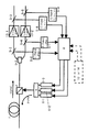
本発明の第1の実施構成を図3に示す。0は入力ポート、1はラマン増幅媒体、2は合波カプラ、3は分岐カプラ、4は合波カプラ、5は波長分離カプラ、6−1乃至6−3は励起光源ブロック、7−1乃至7−3は受光素子、8は励起光制御部をそれぞれ示す。
【0025】
複数の信号光が波長多重された波長多重光がラマン増幅器の入力ポートから、後方励起されたラマン増幅媒体1に入射される。合波カプラ4は中心波長の異なる励起光源ブロック6−1乃至6−3からの平均波長λp1乃至λp3の励起光を合波する波長多重カプラである。合波カプラ2は合波カプラ4からの波長λp1乃至λp3の励起光と複数の信号光を波長多重した波長多重光とをラマン増幅媒体1の中で波長多重する波長多重カプラである。
【0026】
分岐カプラ3はラマン増幅媒体1で増幅された波長多重光を10対1で分岐するビームスプリッタである。波長分離カプラ5は励起光源ブロック6−1乃至6−3からの励起光により生じるラマン利得波長帯域を、3つの波長帯域ブロック(モニタブロック)に分割する波長帯域分岐カプラである。
【0027】
受光素子7−1乃至7−3は波長分離カプラ5で分離した3つの帯域各々を受光し光/電変換する。励起光制御回路8は受光素子からの出力を用いて励起光源ブロック6−1乃至6−3の平均波長λp1乃至λp3の出力パワーを制御する。
【0028】
以下に励起光制御回路8の制御原理について説明をする。
【0029】
励起光源ブロック6−1の平均励起波長をlp1、励起光源ブロック6−1の出力パワーをPp1、励起光源ブロック6−2の平均励起波長をlp2、励起光源ブロック6−2の出力パワーをPp2、励起光源ブロック6−3の平均励起波長をlp3、励起光源ブロック6−3の出力パワーをPp3とする。
【0030】
受光素子7−1で受信する波長帯域ブロック(モニタブロック1;平均波長ls1)の平均出力パワーをPs1とし、受光素子7−2で受信する波長帯域ブロック(モニタブロック2;平均波長ls2)の平均出力パワーをPs2とし、受光素子7−3で受信する波長帯域ブロック(モニタブロック3;平均波長ls3)の平均出力パワーをPs3とする。
【0031】
励起光源ブロック6−1のみを稼動させ、平均励起波長λp1、平均励起出力パワーPp1で動作した場合の、波長多重光の出力を図4(a)に示す。細い実線は、波長帯域ブロック1(平均波長ls1)における出力スペクトルを示し、太い実線は波長帯域ブロック1の平均出力パワーPp1を示している。
【0032】
励起光源ブロック6−2のみを稼動させ平均励起波長λp2、平均励起出力パワーPp2で動作した場合の、波長多重光の出力を図4(b)に示す。細い実線は、波長帯域ブロック2(平均波長ls2)における出力スペクトルを示し、太い実線は波長帯域ブロック2の平均出力パワーPp2を示している。
【0033】
励起光源ブロック6−3のみを稼動させ平均励起波長λp3、平均励起出力パワーPp3で動作した場合の、波長多重光の出力を図4(c)示す。細い実線は、波長帯域ブロック3(平均波長ls3)における出力スペクトルを示し、太い実線は波長帯域ブロック3の平均出力パワーPp3を示している。
【0034】
励起光源ブロック6−1が最も寄与する信号光出力モニタブロックはブロック1であり、励起光源ブロック6−2が最も寄与する信号光出力モニタブロックはブロック2であり、励起光源ブロック6−3が最も寄与する信号光出力モニタブロックはブロック3であることが分かる。
【0035】
同時に、励起光源ブロック6−1は信号光出力モニタブロックls2と信号光出力モニタブロックls3にも寄与し、励起光源ブロック6−2は信号光出力モニタブロックls1と信号光出力モニタブロックls3にも寄与し、励起光源ブロック6−3は信号光出力モニタブロックls1と信号光出力モニタブロックls2にも寄与している。
【0036】
従って、広帯域な光アンプを作るために複数波長の励起光を用いた場合には、一つの励起光源ブロックのパワーを制御すると、励起光により利得が生じる波長帯域は広い範囲に及び、モニタする波長帯域ブロックの複数に影響を及ぼしていることが判る。
【0037】
所定の増幅信号パワーを得るためには励起光源のパワーに利得係数を掛ければ良いので、励起光源ブロック6−1乃至6−3の励起光出力の平均パワー変動量をΔP、受光素子7−1乃至7−3からの得た励起光により利得が生じる帯域の平均出力パワーの変動量をΔPs、平均利得係数をAとすると、
【式1】

【0038】
従って、各波長帯域ブロックの出力パワーの波長特性偏差をなくすためには、波長分離カプラ5で3つに分離した各波長帯域の波長多重光のパワーレベルを同じになるようにΔPpを調整すれば良い。
【0039】
ΔPpは、励起光源の光出力パワーを変動させることで調整でき、また励起波長を変動させ重心波長をシフトさせることでも調整でき、また励起光波長幅を変動することでも調整することができる。ここでは、光出力パワーを変動する調整の例を示す。
【0040】
図4に示したように、一つの励起光源ブロックにより生じる利得波長帯域は広く、各モニタブロック間に跨がり利得を有しているため、一つの励起光源ブロックを変化させた場合に他のモニタブロックの波長に与える影響を考慮して式1を計算する必要がある。言い換えると、各モニタブロックのパワーを各励起光源ブロックごとの光増幅媒体で生じる利得の波長特性を基に各励起光ブロックの出力パワーの制御をおこなう必要がある。
【0041】
ここで、励起光ブロック6−1の平均励起波長lp1の平均出力パワー変動ΔPp1がモニタブロックのブロック1の平均出力パワー変動ΔPs1に及ぼす平均利得係数をA11、励起光源ブロック6−1の励起光波長lp1の平均出力パワー変動ΔPp1がモニタブロックのブロック2の平均出力パワー変動ΔPs2に及ぼす平均利得係数をA12、励起光源ブロック6−1の励起波長lp1の平均出力パワー変動ΔPp1がモニタブロックのブロック3の平均出力パワー変動ΔPs3に及ぼす平均利得係数をA13、励起光源ブロック6−2の励起波長lp2の平均出力パワー変動ΔPp2がモニタブロックのブロック1の平均出力パワー変動ΔPs1に及ぼす平均利得係数をA21、励起光源ブロック6−2の励起波長lp2の平均出力パワー変動ΔPp2が信モニタブロックのブロック2の平均出力パワー変動ΔPs2に及ぼす平均利得係数をA22、励起光源ブロック6−2の励起波長lp2の平均出力パワー変動ΔPp2がモニタブロックのブロック3の平均出力パワー変動ΔPs3に及ぼす平均利得係数をA23、励起光源ブロック6−3の励起波長lp3の平均出力パワー変動ΔPp3がモニタブロックのブロック1の平均出力パワー変動ΔPs1に及ぼす平均利得係数をA31、励起光源ブロック6−3の励起波長lp3の平均出力パワー変動ΔPp2がモニタブロックのブロック2の平均出力パワー変動ΔPs2に及ぼす平均利得係数をA32、励起光源ブロック6−3の励起波長lp3の平均出力パワー変動ΔPp3がモニタブロックのブロック3の平均出力パワー変動ΔPs3に及ぼす平均利得係数をA33と定義する。
【0042】
図5(a)に励起光源ブロック6−1のみを稼動させた場合の、励起光出力パワー差分に対する、モニタブロックのブロック1、モニタブロックのブロック2、モニタブロックのブロック3の平均出力パワー差分を示している。それぞれの傾きがA11、A12、A13に相当する。
【0043】
また、図5(b)に励起光源ブロック6−2のみを稼動させた場合の、励起光出力パワー差分に対する、出力モニタブロックのブロック1、出力モニタブロックのブロック2、出力モニタブロックのブロック3の平均出力パワー差分を示している。それぞれの傾きがA21、A22、A23に相当する。
【0044】
図5(c)に励起光源ブロック6−3のみを稼動させた場合の、励起光出力パワー差分に対する、出力モニタブロックのブロック1、出力モニタブロックのブロック2、出力モニタブロックのブロック3の平均出力パワー差分を示している。それぞれの傾きがA31、A32、A33に相当する。
【0045】
それらを要素とする平均利得係数行列[A]を求めることが出来る。
【式2】
【0046】
波長多重光出力の波長特性偏差を小さくすることは、図6(b)に示すように出力モニタブロックのブロック1、ブロック2、ブロック3の平均出力Ps1乃至Ps3を目的とするラマン増幅された波長多重光出力Pf(全波長帯域の平均出力)に一致させることを意味している。
【式3】
ラマン増幅媒体1でラマン利得が生じる全波長帯域で出力差分(チルト)を小さく抑えるには、上式を満たすように励起光源ブロック6−1乃至6−3の励起光の出力Pp1乃至Pp3の補正量をΔPp1、ΔPp2、ΔPp3を下式から算出すればよい。
【式5】
すなわち、HYPERLINK "JavaScript:void(0)"図3中の励起光制御部8は複数の信号光が波長多重された波長多重光を所定の波長帯域のモニタブロックに分けて出力パワーをモニタし、各波長帯域のモニタブロックの全出力をチャンネル数で割った平均値化処理を行い、全波長帯域での出力パワー差分を小さくするために必要な各励起光源ブロックの励起波長が各モニタブロックの波長に対して及ぼす影響の重み付けを励起光の平均出力パワー差分を上記の式5により計算し、各励起光源ブロックより出力される励起光のパワーを制御すれば良い。
そして、所定の波長特性偏差が得られるまで、1回〜10回程度のフィードバック制御を行う。このような制御処理を行なうことで、励起光により生じるラマン利得波長帯域の平均パワーを一定のパワーPfの値にすることができる。
【0049】
図3の構成に於いて、励起光制御部8はCPU等のプロセッサにより図7のフローにより制御することで実現できる。
ステップ1として:制御処理を開始する。
ステップ2として:受光素子7−1乃至7−3の出力よりモニタブロック内の平均出力パワーPs1乃至Ps3を求める。
ステップ3として:モニタブロック内の平均波長出力パワーPs1乃至Ps3を目的とする波長多重光出力値Pfと比較し、ΔPs1乃至ΔPs3を求める。
ステップ4として:ΔPs1乃至ΔPs3とPfの差分が、許容範囲内の場合は動作を止めステップ7に、許容範囲該の場合は次のステップ5に行く。
ステップ5として:ΔPs1乃至ΔPs3より各励起光が各モニタブロックに及ぼす平均利得係数A11乃至A33の逆行列を用いて励起光源ブロックのλp1乃至λp3のパワーレベルPp1乃至Pp3の制御量ΔPp1乃至ΔPp3を求める。
ステップ6として:現在のPp1乃至Pp3に制御量ΔPp1乃至ΔPp3を加え励起光源ブロック6−1乃至6−3の出力パワーPp1乃至Pp3、を制御する。
ステップ7として:制御処理を終了する。
【0057】
図3では一例として、励起光源ブロックを3つブロックとし、励起光源ブロックからの励起光により生じる利得を生じる波長帯域のモニタブロックは3つに分けているが、これらの数は必要に応じて任意に設定することができる。
【0058】
励起光源ブロックとモニタブロックの数を任意の数に設定した場合をHYPERLINK "JavaScript:void(0)"図8に示す。図中、励起源ブロックの数をn個(6−1乃至6−n)、波長多重光のモニタブロックm個で構成したとする。
【0059】
ここでの励起光により生じるラマン増幅利得の波長帯域を図9に示し、波長分離カプラ5の波長多重光のm個のモニタブロックに分ける。励起光パワー制御の変動量ΔPpはn×1の行列となり、モニタブロック内の.波長多重光パワーの平均値と目的とする制御の値との差分ΔPsはm×1の行列となり、Aはn×mの行列となる。
【式6】
この場合のΔPpiは励起源のブロックの平均出力パワーの変動量、またΔPsjは信号光モニタブロックの平均出力パワーの変動量である。変動量を用いているので、モニタ出力パワーを主信号出力パワーに変換する必要はない。ΔPsjに伴うΔPpiを求めるには[A]の逆行列[A]-1を求めればよいことが分かる。従って、
【式7】
【0061】
第1の実施構成では励起光源ブロックとモニタブロック数は任意に構成できるが、モニタブロックの数は波長多重光に多重されている信号光チャンネル数以下にし、励起光源ブロック化数以上にすることが望ましい。
【0062】
図3の構成における、具体的な構成をHYPERLINK "JavaScript:void(0)"図10に示す。
【0063】
図中24、25はWDMカプラ、61乃至63は偏光合成カプラ、51乃至56はファイバグレーティングフィルタ、81乃至86は半導体レーザをそれぞれ示す。
【0064】
励起光源ブロック6−1乃至6−3は2つの僅かに波長の異なる半導体レーザ81、82の組み合わせ83、84の組み合わせ85、86の組み合わせでそれぞれ構成される。(この例では半導体レーザの波長間隔は約4nm)
【0065】
半導体レーザ81乃至86からの光はファイバグレーティンクフィルタ51乃至56でそれぞれ特定の波長(この例では1429.7nm、1433.7nm、1454.0nm、1480.0nm、1484.5nm、1488.5nmの各波長)で半導体レーザ81乃至86にそれぞれ反射して半導体レーザ81乃至86とファイハグレーティングフィルタ51乃至56で共振構造を取り特定の波長の励起光を出力する。
【0066】
各励起光源ブロックの2つの励起光は偏波構成カプラ61乃至63でそれぞれ偏波合成され励起光源ブロックの出力となる。偏波合成を行うのは、ラマン増幅の偏光依存性を解消するためである。合波カプラ4はWDMカプラ24、25で構成されている。
【0067】
WDMカプラ25は励起光源ブロック6−2からの波長の光を反射して、励起光源ブロック6−3からの波長を通過する特性を有している。WDMカプラ24は励起光源ブロック6−1からの波長の光を反射して、励起光源ブロック6−2、励起光源ブロック6−3からの波長を通過する特性を有している。
【0068】
図10に於いては励起光源ブロック内の半導体レーザとファイバグレーティングの中心は僅かに波長が異なる光を出力しているが、同じ波長の光としても良い。また、励起光源ブロックの光は必ずしも複数半導体レーザで構成する必要はなく、偏光無依存の励起光源等を用いる場合は単一の光源で有っても良い。
【0069】
第1実施例では目標となる波長多重光出力値をPfとして、全ての波長帯域の平均パワーがPfに揃うように制御しているため、全ての波長帯域にて出力一定制御を行なうことができる。この出力一定制御の変形例として、モニタブロックの波長帯域毎にPfをPf1、Pf2、Pf3と定めて、比較することにより、波長ブロック単位で個別に出力一定制御を行なうことができる。
【0070】
この場合図7のフローチャートのステップ4でPfの代わりに、各モニタブロックに対応して、Pf1、Pf2、Pf3をさだめる。そして、Pf1、Pf2、Pf3より、それぞれ対応するPs1、Ps2、Ps3を引くことで励起光制御部8の制御を行なうことができる。
【0070】
またPfを変える変わり図11に示すように図3の受光素子7−1乃至7−3の前段に可変または固定の減衰器71乃至73を設けることで、任意にモニタブロック単位で重み付けを行ない、波長ブロック単位で個別に出力一定制御を行なうことができる。
【0071】
また、第1の実施例はラマン増幅媒体としては、通常の1.3ゼロミクロンファイバはもちろん、実効断面積が小さく非線形が大きい分散補償ファイバ(DCF)、分散シフトファイバ(DSF)、ノンゼロ分散シフトファイバ(NZDSF)を用いることも可能である。これらの非線形が大きいファイバを用いると必要な利得をえるためのラマン増幅媒体となるファイバは短くて済み、集中増幅を可能にすることができる。
【0072】
第1の実施構成ではモニタブロックは波長分離カプラ5、10と受光素子7−1乃至11−1で構成しているが、これらはスペクトルアナライザで代用することが可能である。
【0073】
第2の実施構成を図12に示す。図12に於いて図3と同じ構成は同じ番号で示す。図中9は分岐カプラ、10は波長分離カプラ、11−1乃至11−3は受光素子をそれぞれ示す。分岐カプラ9はラマン増幅器の入力ポートに設け、入力ポートに入力される複数の信号光波長多重された波長多重光を、分岐比10:1で分岐するビームスプリッタである。
【0076】
波長分離カプラ10は分岐カプラ9の1/10側のポートからの波長多重光を、波長分離カプラ5と同じように、励起光源ブロック6−1乃至6−3からの励起光により生じるラマン利得波長帯域を、3つの波長帯域ブロック(モニタブロック)に分離する波長分離カプラである。受光素子11−1乃至11−3は3つのモニタブロックにそれぞれ対応して設けられ、各モニタブロックの光パワーを電気信号に変換する。
【0077】
波長分離カプラ10で分離したモニタブロック1の平均波長をls1、平均出力パワーをPin_s1、モニタブロック2の平均波長をls2、平均出力パワーをPin_s2、モニタブロック3の平均波長をls3、平均出力パワーをPin_s3とする。
【0078】
その後、信号光は後方励起されたラマン増幅媒体1に入射される。励起光源ブロック6−1乃至6−3は図10のように構成されても良いし、第1の実施例と同様のさまざまな構成で実現可能である。
【0079】
増幅媒体1で増幅された信号はその後、10対1の分岐カプラ3で分岐され、その1/10ポートから出力された信号光は、図3と同様に波長分離カプラ5で、入力ポート側に設けた波長分離カプラ10と同じ3つの波長帯域ブロックに分けられる。波長分離カプラ5の波長帯域ブロックは波長分離カプラ10のモニタブロックの平均波長ls1、ls2、ls3にそれぞれ対応している。受光素子7−1乃至7−3にて波長多重光出力パワーを光電変換する。
【0080】
図3と同様に波長分離カプラ5のモニタブロックの平均波長ls1の平均出力パワーをPs1、モニタブロックの平均波長ls2の平均出力パワーをPs2、モニタブロックの平均波長ls3の平均出力パワーをPs3とする。励起光制御部8では受光素子7−1乃至7−3及び11−1乃至11−3からのモニタ入力により利得が所定の値となるように制御する。
【0081】
図12における具体的な制御部8の動作の説明を以下に述べる。各モニタブロックの平均利得G1、G2、G3は増幅媒体1で増幅された波長多重光を波長分離カプラで分離して受光素子7−1乃至7−3で得たPs1、Ps2、Ps3、より入力ポート側の波長分離カプラ10で分離して受光素子11−1乃至11−3で得たPin_s1、Pin_s2、Pin_s3を引くことにより得られる。
【式8】
各モニタブロックの励起光平均出力パワーと各モニタブロックの波長光平均利得は各モニタブロックの平均利得係数で結び付けることができ、励起光平均出力パワー変動量をΔPp、信号光平均出力パワーの変動量をΔG、平均利得係数をAとすると、
【式9】
【0083】
実施例1で使用した[A]は励起光平均出力パワーの信号光平均出力パワーの傾きを示しているので、ここで定義する利得Aに対しても同様に下記の関係が成り立つ。
【式10】
目的とする利得レベルを全波長帯域の平均利得Gfとし、各モニタブロックの平均利得をG1、G2、G3とし、GfとG1の差分をΔG1、GfとG2の差分をΔG2、GfとG3の差分をΔG3とする。
【式11】
全波長帯域で利得波長偏差(チルト)を小さく抑えるには、各モニタブロック間の平均利得を揃えて全波長帯域の平均利得Gfと一致するように制御すれば良い。
【0086】
ここで、Gfは利得を一定にするための予め定めた値とすることで、全ての波長が定めた利得に一定に制御できる。
【式12】
【式13】
すなわち、励起光制御部8は波長多重光のモニタブロックの全出力を取得し、モニタブロックの全出力をチャンネル数で割った平均値化処理を行い、全波長帯域での利得差分を小さくするために、各励起光源ブロックによる利得が各モニタブロックの波長に及ぼす影響を考慮して、必要な励起光の平均出力差分を計算し、モニタブロックの励起光発生手段を制御する働きをしている。ラマン光増幅器の各モニタブロックの利得の波長特性偏差がなくなるまで、1回〜10回程度のフードバック制御を行う。
【0088】
図13に励起光制御部8の動作フローチャートの一例を示す。
ステップ1として:制御開始する。
ステップ2として:光増幅媒体の出力側に設けた波長分離カプラ5の各モニタブロックのパワーPs1乃至Ps3より入力側に設けた波長分離カプラ5の各モニタブロックのパワーPin_s1乃至Pin_s3を引き各モニタブロックの利得G1乃至G3を求める。
ステップ3として:目標とする利得Gfとモニタブロック内の利得G1乃至G3fと比較し、差分ΔG1乃至ΔG3を求める。
ステップ4として:ΔG1乃至ΔG3とGfとの差分が、許容範囲内の場合は動作を止めステップ7に、許容範囲該の場合は次のステップ5に行く。
ステップ5として:ΔG1乃至ΔG3より各励起光が各モニタブロックに及ぼす平均利得係数A11乃至A33を用いて励起光源ブロックのλp1乃至λp3のパワーレベルp1乃至Pp3の制御量ΔPp1乃至ΔPp3を求める。
ステップ6として:現在のPp1乃至Pp3に制御量ΔPp1乃至ΔPp3を加え励起光源ブロック6−1乃至6−3の出力パワーPp1乃至Pp、3を制御する。
ステップ6として:制御処理を終了する。
以上の様な流れで励起光制御部8は励起光源ブロックを制御する。
【0097】
第2の実施例においても第1の実施例同様に、励起光源ブロックとモニタブロックの数は任意の数にすることができる。即ち、励起光源ブロックをn個とし、モニタブロックの数をm個とした場合は、式10乃至式13を式14乃至式18と書き換えることができる。
【式14】
【0098】
第2の実施構成でも第1の実施構成と同様に励起光源ブロックとモニタブロック数は任意に構成できるが、モニタブロックの数は波長多重光に多重されている信号光チャネル数以下にし、励起光源ブロック化数以上にすることが望ましい。
【0099】
また、第二の実施例では第1の実施例と同様に、ラマン増幅媒体を通常の1.3ゼロミクロンファイバはもちろん、実効断面積が小さく非線形が大きい分散補償ファイバ(DCF)、分散シフトファイバ(DSF)、ノンゼロ分散シフトファイバ(NZDSF)を用いることも可能である。これらの非線形が大きいファイバを用いると必要な利得を得るためのラマン増幅媒体となるファイバは短くて済み、集中増幅をすることができる。
【0101】
ラマン増幅媒体1となる光ファイバの実効断面積が小さく非線形が強いファイバの場合はラマン増幅媒体1を短く構成できるが、通常の1.3μmゼロ分散ファイバの場合は励起パワーにもよるが約40Km以上必要な場合もある。そこで、図14に図12ラマン増幅器の波長多重光入力の通知を実際の伝送路を用いて行なう例を示す。
【0102】
図14では監視制御部12で各モニタブロックのパワーを検出し、その結果を情報化して波長λOSCの波長で合波カプラ13を介して、ラマン増幅媒体1となる伝送路に送信する。この波長λOSCの信号は波長分離カプラ5により分離され監視制御部14で検出され励起光制御部8に供給される。図14では波長λOSCを波長分離カプラ5で分離したが、伝送路より分岐カプラを別途設け、監視制御信号を分離して監視制御部14に入力しても良い。
【0103】
図13の説明ではGfを全てのモニタブロックにて同じ値を用いることにより、励起光源ブロックからの励起光により、増幅媒体1で生じる利得波長帯域で、このような構成にすることでラマン増幅媒体1が伝送路を用いた場合でも利得を一定に制御することができるが、ここで、Gfを各モニタブロックごとに別の利得を設定することで、各モニタブックの波長帯域毎重み付けした利得による利得一定制御を行なうことができる。
【0104】
また、第2の実施例でも第1の実施例同様に、上記の重み付けの処理は全ての波長ブロックでGfに一定にし、モニタブロックの単位に受光素子の前段に可変または固定の光減衰器71乃至73を設けることで重み付けを行なう処理を行なっても良い。
【0105】
第2の実施構成ではモニタブロックは波長分離カプラ5、10と受光素子7−1乃至11−1で構成しているが、これらはスペクトルアナライザで代用することが可能である。
【0106】
第3の実施構成として、第1の実施例と第2の実施例を希土類元素ドープファイバ(例えばエルビウプドープファイバ)を用いた光増幅器との組み合わせについて図15を用いて説明する。図中13−1は第1の希土類元素ドープファイバ増幅器、13−2は第2の希土類元素ドープファイバ増幅器、5−1は波長帯域分離カプラ、5−2乃至5−5は分岐カプラ、5−6は第1の波長帯域モニタ、5−7は第2の波長帯域モニタ、5−8は第1のスペクトルアナライザ、5−9は第2のスペクトルアナライザをそれぞれ示す。図3および図12と同一機能のブロックと同一の機能のブロックは同一符号で示す。
【0107】
波長帯域分離カプラ5−1はラマン増幅媒体1で増幅された波長多重光を第一の波長帯域(C−band帯域1530nm乃至1557nm)と第2の波長帯域(Lband帯域1570nm乃至1610nm)に分割して出力する。
【0108】
第1の希土類元素ドープファイバ増幅器13−1は第1の波長帯域に対して利得を有するエルビウムドープファイバ(EDF)からなる光増幅器である。第2の希土類元素ドープファイバ増幅器13−2は第2の波長帯域に対して利得を有するエルビウムドープファイバ(EDF)からなる光増幅器である。波長帯域分離カプラ5−1で分岐された光は第1の希土類元素ドープファイバ増幅器と第2の希土類元素ドープファイバ増幅器にてそれぞれの波長帯域の光が増幅される。
【0109】
分岐カプラ5−2、5−3は第1の波長帯域の光を10対1程度で分岐する分岐カプラである。分岐カプラ5−4、5−5は第2の波長帯域の光を10対1程度で分岐する分岐カプラである。
【0110】
第1の波長帯域モニタ5−6は分岐カプラ5−2で分岐された第1の波長帯域の光のパワーをモニタする。第2の波長帯域モニタ5−7は分岐カプラ5−4で分岐された第2の波長帯域の光のパワーをモニタする。
【0111】
励起光制御回路8は第1及び第2の波長モニタ5−6、5−7の出力をもとに第1のスペクトラルアナライザ5−8及び第2のスペクトラルアナライザ5−9の出力パワーの校正を行う。
【0112】
5−8、5−9の出力を1528.773〜1552.122nm、1552.524〜1563.455nm、1570.416〜1581.601nm、1582.018〜1607.035nmの3つの波長帯域ブロックに分けて、各モニタブロックの平均出力を求め励起光6−1乃至6−3を制御する。
【0113】
第2の実施構成との組み合わせの場合は図12及び図14の波長分離カプラ10からの出力を用いる場合と監視制御波長信号OSCを用い監視制御部14からのラマン増幅される前の信号を検出して制御を行なう方法を用いることもできる。
【0114】
[付記1]複数の信号光を波長多重した波長多重光をラマン増幅するための光増幅媒体と、複数の波長の異なる励起光を発生する複数の励起光源と、該複数の励起光を合波する第1光合波手段と、複数の信号光と該励起光を合波する第2光合波手段と、該増幅媒体で増幅された該波長多重光を複数の波長帯域に分割してパワーを検出するモニタ手段と、該モニタ手段の各波長帯域のパワーと該各励起光ごとに該光増幅媒体で生じる利得の波長特性を基に該各励起光の出力パワーを制御する励起光制御手段を設けたことを特徴とする光増幅器。
【0115】
[付記2]該励起光制御手段は該モニタの該各波長帯域間のパワーの波長特性偏差が小さくなるように該各励起光の出力を制御する事を特徴とする付記1記載の光増幅器。
【0116】
[付記3]該励起光制御手段は該各波長帯域の出力パワーが各々特定の値になるように該各励起光の出力を制御する事を特徴とする付記1記載の光増幅器。
【0117】
[付記4]該励起光制御手段は該各波長帯域の出力パワーが全て特定の値になるように該各励起光の出力を制御する事を特徴とする付記1記載の光増幅器。
【0118】
[付記5]該励起光制御手段は該各波長帯域の出力パワーが全て特定の値になるように該各励起光の出力を制御する事を特徴とする付記1記載の光増幅器。
【0119】
[付記6]複数の信号光を波長多重した光をラマン増幅するための光増幅媒体と、複数の波長の異なる励起光を発生する複数の励起光源と、該複数の励起光を合波する第1光合波手段と、複数の信号光と該励起光を合波する第2光合波手段と、該増幅媒体に入射されるパワーを検出する入力モニタ手段と、該増幅媒体で増幅したパワーを検出する出力モニタ手段と、該入力モニタ手段及び該出力モニタ手段に基づき該各励起光の出力パワーを制御する励起光制御手段を設けたことを特徴とする光増幅器。
【0120】
[付記7]該入力モニタ手段は該増幅媒体に入射される該波長多重光を複数の波長帯域に分割してパワーを検出し、該出力モニタ手段は該増幅媒体で増幅した該波長多重光を複数の波長帯域に分割してパワーを検出することを特徴とする付記6記載の光増幅器。
【0121】
[付記8]該制御手段は該入出力モニタ手段の同じ波長帯域のパワーを比較して得た該各波長帯域ごとの利得と該各励起光ごとの該光増幅媒体で生じる利得の波長特性を基に該各励起光の出力を制御する付記7記載の光増幅器。
【0122】
[付記9]該励起光制御手段は該モニタの該各波長帯域間の利得の波長特性偏差が小さくなるように該各励起光の出力を制御する事を特徴とする付記8記載の光増幅器。
【0123】
[付記10]該励起光制御手段は該各波長帯域の利得が各々特定の値になるように該各励起光の出力パワーを制御する事を特徴とする付記8記載の光増幅器。
【0124】
[付記11]該励起光制御手段は該各波長帯域の利得が全て特定の値になるように該各励起光の出力を制御する事を特徴とする付記8記載の光増幅器。
【発明の効果】
【0125】
ラマン増幅器の広帯域化及び、出力と利得の波長特性を平坦にするために、励起光源を複数化し、励起光により利得が生じた結果をモニタする際に、励起光源を3個以上にした場合の制御に関する。
【0126】
本発明では、励起光発生手段をブロック化し、信号光の入出力モニタの波長帯域を励起光発生手段のブロック化数以上及び信号チャンネル数以下に分けてモニタすることで、簡便な制御アルゴリズムを用いて出力パワーと利得の波長特性偏差の制御及び、出力一定制御、利得一定制御を可能とするものである。
【図面の簡単な説明】
【図1】 ラマン増幅時の励起光と利得波長の関係を示す図
【図2】 励起光源を波長多重化することで、ラマン増幅の帯域拡大を示す図
【図3】 第1の実施構成を示す図
【図4】 単独の励起光源ブロックの波長特性を示す図
【図5】 単独の励起光源ブロックの波長特性を示す図
【図6】 波長特性を一定にするための制御を説明する図
【図7】 第1の実施構成の励起光制御部の制御フローチャート
【図8】 第1の実施構成に於いて励起光源ブロック数とモニタブロック数を任意にした場合の構成図
【図9】 モニタブロック数を任意にした場合の波長特性を示す図
【図10】 図3及び図8の構成の励起光源ブロックと波長合波カプラの具体的構成を示す図
【図11】 第1の実施構成に於いて重み付けした場合の構成を示す図
【図12】 第2の実施構成を示す図
【図13】 第2の実施構成の励起光制御部の制御フローチャート
【図14】 第2の実施構成の変形例を示す図
【図15】 第3の実施構成を示す図
【符号の説明】
0:入力ポート、
1:ラマン増幅媒体
2:合波カプラ、
3:分岐カプラ、
4:合波カプラ、
5:波長分離カプラ、
6−1乃至6−3:励起光源ブロック、
7−1乃至7−3:受光素子、
8:励起光制御部BACKGROUND OF THE INVENTION
[0001]
The present invention is a Raman amplifier that can be used for amplification of signal light in various optical communication systems, and is particularly suitable for amplification of wavelength division multiplexed light.
[Prior art]
[0002]
Most of the optical amplifiers used in the current optical communication system are rare earth doped optical fiber amplifiers. In particular, an optical fiber amplifier (abbreviated as EDFA) doped with Er is widely used. The wavelength division multiplexing (WDM) optical transmission system utilizing the wide gain band of EDFA is a transmission system capable of increasing communication capacity by transmitting optical signals of a plurality of wavelengths through one optical fiber.
[0003]
This WDM optical transmission system has the advantages that the existing optical fiber can be used and the introduction cost is low, and the use of an optical amplifier or the like makes the transmission line bit-rate free and facilitates future upblade.
[0004]
The band with a small loss (about 0.3 dB / km or less) of the optical fiber transmission line is 1450 nm to 1650 nm, but the practical amplification band of EDFA is 1530 nm to 1610 nm. EDFA is only applied to some of these. In this context, research and development of technologies that increase the transmission capacity with a single optical fiber are being actively pursued.
[0005]
On the other hand, in a WDM optical communication system, in order to obtain a predetermined transmission characteristic, it is necessary to suppress variations in optical power between channels to 1 dB or less in each optical repeater stage.
This is because the upper limit of optical power is limited by the nonlinear effect, and the lower limit is limited by the received SNR.
[0006]
Here, it is necessary to reduce loss wavelength characteristics of a transmission line, a dispersion compensating fiber, and the like constituting the WDM optical communication system. In an actual WDM optical communication system, wavelength characteristics occur in the optical transmission power between channels due to the following matters.
(1) Loss wavelength characteristics of transmission line due to Rayleigh scattering
(2) Wavelength characteristics of dispersion compensator
(3) Loss wavelength characteristics of transmission line due to stimulated Raman scattering
(4) Wavelength characteristics of gain of optical amplifier
(5) Temperature characteristics of transmission line, dispersion compensator and optical amplifier
[0007]
Specifically, for example, when the wavelength band of the signal is 1530 to 1610 nm and a 1.3 μm zero dispersion single mode fiber having a length of 100 km is used for the optical transmission line, it is caused by the above (1) and (3). The optical transmission power deviation generated in this manner is 7 dB.
[0007]
The deviation due to the above (2) is about 0.5 dB when a general dispersion compensating fiber is used as a dispersion compensator, and the deviation due to the above (4) is when the general EDFA is used. 1 dB. Furthermore, the deviation due to the above (5) can be estimated to be about 0.3 dB when each optical device is used.
[0008]
As described above, it is understood that the wavelength characteristic of the loss of the transmission line due to stimulated Raman scattering has the greatest influence on the wavelength characteristic of the signal.
[0009]
The key component of the current wavelength division multiplexing transmission system is an EDFA that can amplify multi-wavelength signals at once. This EDFA transmits low noise, outputs a predetermined output, compensates for a predetermined gain, and outputs variations between channels. It had a characteristic that can be reduced.
[0010]
In the future, in order to increase transmission capacity and enable ultra-long distance transmission, optical amplifiers having different characteristics while having these characteristics of EDFA are required. As an expansion of the band for increasing the transmission capacity, a Raman amplifier has attracted attention. The Raman amplifier can amplify at a frequency that is Stokes-shifted by the Raman shift amount of the amplification medium from the pumping light frequency. If a pumping light source having an arbitrary wavelength can be prepared, it can be amplified at an arbitrary wavelength.
[0011]
For example, J. et al. Kani et al., Electronics Letter, vol. 34 pp. 1745 reports a gain of 1505-1522 nm outside the EDFA band using an excitation wavelength of 1420 nm.
[0012]
In addition, M.M. Takeda et al., OSA TOPS vol. 30 pp. In 101-105 (1999) and Japanese Patent Laid-Open No. 2000-98433, a Raman amplifier is used as a correction for the output deviation of the EDFA, and the Raman amplifier is used as a transmission wavelength loss correction for the transmission line due to stimulated Raman scattering. Attention has been focused on Raman amplifiers for the reason that pump light can be introduced into the channel and the transmission channel can be used for output deterioration correction using a Raman amplification medium.
[0013]
The following three applications can be considered as Raman amplifiers: (a) Use of EDFA outside the applicable wavelength band, (b) EDFA output deviation correction and optical SNR improvement, (c) Stimulated Raman scattering compensation of transmission line It is. In the wavelength division multiplexing transmission system, the characteristics first required for all of these applications are a wide band and a flat wavelength characteristic.
[Problems to be solved by the invention]
[0014]
In order to widen the bandwidth of the Raman amplifier, it is considered to use a plurality of pumping lights having different wavelengths as disclosed in JP-A-2000-98433. JP 2000-98433 and M.K. Takeda et al. OSA TOPS vol. 30, pp. In 101-105 (1999), the Raman amplification output is monitored or the output after the inline amplifier is inserted after the Raman amplifier is used to secure the band of the Raman amplifier so that the gain deviation or the output deviation is reduced. The output of a plurality of excitation LDs is controlled.
[0015]
However, the embodiment of Japanese Patent Application Laid-Open No. 2000-98433 only shows the case of controlling the excitation light sources divided into two groups. Takeda et al. Also shows a case where two excitation light sources are used. When there are three or more excitation light sources, algorithms for constant output power control, constant gain control, and wavelength characteristic flattening control become very complicated.
[0016]
In other words, as the number of excitation wavelengths or the number of excitation light sources increases in order to broaden the bandwidth and flatten the wavelength characteristics, a complex control algorithm is required but there is no appropriate algorithm, and an optical system of a Raman amplifier using a multi-wavelength excitation light source. This is a factor that hinders the practical application of the system.
[Means for Solving the Problems]
[0017]
In the present invention, when performing Raman amplification, the output power is constantly controlled so as to widen the band using a plurality of pumping light wavelengths or pumping light sources, and to flatten the wavelength characteristics or to have characteristics having a specific inclination. A control algorithm for easily performing constant gain control and wavelength characteristic flattening control is provided.
[0018]
The first means is to input a wavelength-multiplexed light in which a plurality of signal lights arranged in any of a plurality of channels are wavelength-multiplexed and to perform Raman amplification, and to output a plurality of pump lights having different wavelengths, respectively. A plurality of pumping light sources, pumping light supply means for outputting the plurality of pumping lights to the optical amplifying medium, and an output for monitoring the power of the wavelength multiplexed light output from the amplifying medium for each of a plurality of wavelength bands Excitation light control means for controlling the plurality of excitation light sources based on the monitoring means, the monitoring result of the output monitoring means, and the wavelength characteristics of the gain generated in the optical amplification medium by the excitation of each of the plurality of excitation lights The plurality of wavelength bands each include at least one of the channels, and are wavelength bands that are Raman-amplified in the optical amplification medium by any of the plurality of pump lights. And wherein the door.
[0019]
The second means is to input a wavelength-multiplexed light in which a plurality of signal lights arranged in any of a plurality of channels are wavelength-multiplexed, an optical amplifying medium for performing Raman amplification, and a plurality of pumping lights having different wavelengths, respectively. A plurality of pumping light sources for outputting, a pumping light supplying means for outputting the plurality of pumping lights to the optical amplifying medium, and monitoring the power of the wavelength multiplexed light input to the optical amplifying medium for each of a plurality of wavelength bands; Input monitoring means, and output monitoring means for monitoring the power of each of the plurality of wavelength bands of the wavelength multiplexed light output from the optical amplification medium;
A monitoring result of the input monitoring means and the output monitoring means, and a pumping light control means for controlling the plurality of pumping light sources based on a wavelength characteristic of a gain generated in the optical amplifying medium by each pumping of the plurality of pumping lights. The plurality of wavelength bands each include at least one of the channels, and are wavelength bands that are Raman-amplified in the optical amplification medium by any of the plurality of pump lights. To do.
[0020]
The third means is to input a wavelength-multiplexed light in which a plurality of signal lights arranged in any one of a plurality of channels are wavelength-multiplexed to perform Raman amplification, and to output a plurality of pumping lights having different wavelengths, respectively. A plurality of pumping light sources, pumping light supply means for outputting the plurality of pumping lights to the optical amplifying medium, and the wavelength multiplexed light output from the amplifying medium, the first wavelength band and the second wavelength band A band separation means for separating the first wavelength band, a first rare earth element doped fiber for amplifying the separated first wavelength band light, and a second rare earth element for amplifying the separated second wavelength band light. A doped fiber, a first monitor means for monitoring the output light of the first rare earth element doped fiber, a second monitor means for monitoring the output light of the second rare earth element doped fiber, the first monitor means, Of the second monitoring means And an excitation light control means for controlling each of the plurality of excitation light sources on the basis of the result of the detection and the wavelength characteristic of the gain generated in the optical amplification medium by the excitation of each of the plurality of excitation lights. The plurality of wavelength bands each include at least one of the channels, and are wavelength bands that are Raman-amplified in the optical amplification medium by any of the plurality of excitation lights.
[0021]
A fourth means is a Raman pumping light source that pumps an optical amplifying medium that performs Raman amplification by inputting wavelength-multiplexed light in which signal light arranged in a plurality of channels is wavelength-multiplexed, and a plurality of pumps having different wavelengths. A plurality of pumping light sources that respectively output light, a pumping light supply unit that outputs the plurality of pumping lights to the optical amplification medium, and at least one channel of the wavelength-multiplexed light output from the amplification medium. Monitoring means for monitoring the power for each of a plurality of wavelength bands included, the monitoring result of the monitoring means, and the wavelength characteristics of the gain generated in the optical amplifying medium due to the excitation of each of the plurality of excitation lights. And pumping light control means for controlling the output power of each pumping light.
Embodiment
[0022]
The detailed description of the present invention will be described below. As shown in FIG. 1, the Raman amplification produces a gain at the signal wavelength shifted from the pumping light wavelength by the Raman shift amount of the amplification medium, and the Raman shift amount and the Raman band are given uniquely to the substance (amplification medium). Is.
[0023]
HYPERLINK "JavaScript: void (0)" Figure 1 shows that when the excitation wavelength is shifted to the longer wavelength side, the center wavelength and gain band of the gain are shifted to the longer wavelength side by the same amount as the shift amount of the excitation wavelength. Has been. Therefore, Raman amplification is an optical amplification technique that can obtain a gain at an arbitrary wavelength as long as an excitation light source having an arbitrary wavelength is prepared. By making the excitation light sources having slightly different excitation wavelengths incident on the amplification medium at once, broadband optical amplification can be performed as shown in FIG.
[0024]
A first embodiment of the present invention is shown in FIG. 0 is an input port, 1 is a Raman amplification medium, 2 is a multiplexing coupler, 3 is a branching coupler, 4 is a multiplexing coupler, 5 is a wavelength separation coupler, 6-1 to 6-3 are excitation light source blocks, 7-1 to 7-3 is a light receiving element, and 8 is an excitation light control unit.
[0025]
Wavelength multiplexed light obtained by wavelength multiplexing a plurality of signal lights is incident on the
[0026]
The branching
[0027]
The light receiving elements 7-1 to 7-3 receive each of the three bands separated by the
[0028]
The control principle of the excitation
[0029]
The average excitation wavelength of the excitation light source block 6-1 is l p1 The output power of the excitation light source block 6-1 is P p1 The average excitation wavelength of the excitation light source block 6-2 is l p2 The output power of the excitation light source block 6-2 is P p2 The average excitation wavelength of the excitation light source block 6-3 is l p3 The output power of the excitation light source block 6-3 is P p3 And
[0030]
Wavelength band block (monitor
[0031]
Only the excitation light source block 6-1 is operated, and the average excitation wavelength λ p1 , Average excitation output power P p1 FIG. 4 (a) shows the output of wavelength multiplexed light when operating in FIG. The thin solid line is the wavelength band block 1 (average wavelength l s1 ), The thick solid line shows the average output power P of the
[0032]
Only the excitation light source block 6-2 is operated, and the average excitation wavelength λ p2 , Average excitation output power P p2 FIG. 4 (b) shows the output of wavelength multiplexed light when operating in FIG. The thin solid line is the wavelength band block 2 (average wavelength l s2 ), The thick solid line shows the average output power P of the
[0033]
Only the excitation light source block 6-3 is operated, and the average excitation wavelength λ p3 , Average excitation output power P p3 FIG. 4C shows the output of wavelength-multiplexed light when operating in FIG. The thin solid line indicates the wavelength band block 3 (average wavelength l s3 ), The thick solid line shows the average output power P of the
[0034]
The signal light output monitor block to which the excitation light source block 6-1 contributes most is the
[0035]
At the same time, the excitation light source block 6-1 is a signal light output monitor block l. s2 And signal light output monitor block l s3 The excitation light source block 6-2 is a signal light output monitor block l. s1 And signal light output monitor block l s3 The excitation light source block 6-3 is also a signal light output monitor block l. s1 And signal light output monitor block l s2 Has also contributed.
[0036]
Therefore, when using multiple wavelengths of pumping light to make a broadband optical amplifier, controlling the power of one pumping light source block results in a wide range of wavelength bands where gain is generated by the pumping light. It can be seen that multiple band blocks are affected.
[0037]
In order to obtain a predetermined amplified signal power, it is sufficient to multiply the power of the excitation light source by a gain coefficient. Therefore, the average power fluctuation amount of the excitation light output of the excitation light source blocks 6-1 to 6-3 is ΔP, and the light receiving element 7-1. To the variation amount of the average output power in the band where the gain is generated by the pumping light obtained from 7 to 7-3. s If the average gain coefficient is A,
[Formula 1]
[0038]
Therefore, in order to eliminate the wavelength characteristic deviation of the output power of each wavelength band block, ΔP is set so that the power level of the wavelength multiplexed light in each wavelength band separated into three by the
[0039]
ΔP p Can be adjusted by changing the optical output power of the excitation light source, can be adjusted by changing the excitation wavelength and shifting the centroid wavelength, and can also be adjusted by changing the excitation light wavelength width. Here, an example of adjustment for varying the optical output power is shown.
[0040]
As shown in FIG. 4, since the gain wavelength band generated by one excitation light source block is wide and has a gain across each monitor block, when one excitation light source block is changed, another monitor It is necessary to calculate
[0041]
Here, the average excitation wavelength l of the excitation light block 6-1 p1 Average output power fluctuation ΔP p1 Is the average output power fluctuation ΔP of block 1 of the monitor block s1 The average gain factor on 11 The excitation light wavelength l of the excitation light source block 6-1 p1 Average output power fluctuation ΔP p1 Is the average output power fluctuation ΔP of block 2 of the monitor block s2 The average gain factor on 12 The excitation wavelength l of the excitation light source block 6-1 p1 Average output power fluctuation ΔP p1 Is the average output power fluctuation ΔP of the monitor block 3 s3 The average gain factor on 13 The excitation wavelength l of the excitation light source block 6-2 p2 Average output power fluctuation ΔP p2 Is the average output power fluctuation ΔP of block 1 of the monitor block s1 The average gain factor on twenty one The excitation wavelength l of the excitation light source block 6-2 p2 Average output power fluctuation ΔP p2 Is the average output power fluctuation ΔP of block 2 of the communication monitor block s2 The average gain factor on twenty two The excitation wavelength l of the excitation light source block 6-2 p2 Average output power fluctuation ΔP p2 Is the average output power fluctuation ΔP of the monitor block 3 s3 The average gain factor on twenty three The excitation wavelength l of the excitation light source block 6-3 p3 Average output power fluctuation ΔP p3 Is the average output power fluctuation ΔP of block 1 of the monitor block s1 The average gain factor on 31 The excitation wavelength l of the excitation light source block 6-3 p3 Average output power fluctuation ΔP p2 Is the average output power fluctuation ΔP of block 2 of the monitor block s2 The average gain factor on 32 The excitation wavelength l of the excitation light source block 6-3 p3 Average output power fluctuation ΔP p3 Is the average output power fluctuation ΔP of the monitor block 3 s3 The average gain factor on 33 It is defined as
[0042]
FIG. 5A shows the average output power difference between the
[0043]
In addition, when only the pumping light source block 6-2 is operated in FIG. 5B, the output
[0044]
The average output of
[0045]
An average gain coefficient matrix [A] having them as elements can be obtained.
[Formula 2]
[0046]
Reducing the wavelength characteristic deviation of the wavelength-multiplexed light output means that the average output P of the
[Formula 3]
In order to keep the output difference (tilt) small in the entire wavelength band where the Raman gain occurs in the
[Formula 5]
That is, the HYPERLINK “JavaScript: void (0)” excitation
Then, feedback control is performed about 1 to 10 times until a predetermined wavelength characteristic deviation is obtained. By performing such control processing, the average power in the Raman gain wavelength band generated by the pumping light is made constant power P. f The value can be
[0049]
In the configuration of FIG. 3, the excitation
As step 1: Control processing is started.
As Step 2: Average output power P in the monitor block from outputs of the light receiving elements 7-1 to 7-3 s1 To P s3 Ask for.
As Step 3: Average wavelength output power P in the monitor block s1 To P s3 Wavelength-multiplexed light output value P for f ΔP compared to s1 To ΔP s3 Ask for.
As step 4: ΔP s1 To ΔP s3 And P f If the difference is within the allowable range, the operation is stopped, and the operation is stopped at
As step 5: ΔP s1 To ΔP s3 Λ of the excitation light source block using the inverse matrix of the average gain coefficients A11 to A33 that each excitation light exerts on each monitor block. p1 To λ p3 Power level P p1 To P p3 Control amount ΔP p1 To ΔP p3 Ask for.
As step 6: current P p1 To P p3 Control amount ΔP p1 To ΔP p3 Output power P of the excitation light source blocks 6-1 to 6-3 p1 To P p3 , Control.
Step 7: The control process is terminated.
[0057]
In FIG. 3, as an example, there are three pump light source blocks, and the wavelength band monitor blocks that generate the gain generated by the pump light from the pump light source block are divided into three, but these numbers are arbitrary as required. Can be set to
[0058]
A case where the number of excitation light source blocks and monitor blocks is set to an arbitrary number is shown in FIG. 8 for HYPERLINK “JavaScript: void (0)”. In the figure, it is assumed that the number of excitation source blocks is n (6-1 to 6-n) and m is a monitor block of wavelength multiplexed light.
[0059]
The wavelength band of the Raman amplification gain generated by the pumping light here is shown in FIG. 9 and divided into m monitor blocks of the wavelength multiplexed light of the
[Formula 6]
ΔP in this case pi Is the amount of fluctuation in the average output power of the block of the excitation source, and ΔP sj Is the fluctuation amount of the average output power of the signal light monitor block. Since the fluctuation amount is used, it is not necessary to convert the monitor output power to the main signal output power. ΔP sj ΔP associated with pi To obtain the inverse matrix [A] of [A] -1 It can be seen that Therefore,
[Formula 7]
[0061]
In the first embodiment, the number of pumping light source blocks and the number of monitor blocks can be arbitrarily configured, but the number of monitor blocks should be less than or equal to the number of signal light channels multiplexed in the wavelength multiplexed light and more than the number of pumping light source blocks. desirable.
[0062]
A specific configuration in the configuration of FIG. 3 is shown in FIG. 10 of HYPERLINK “JavaScript: void (0)”.
[0063]
In the figure, 24 and 25 are WDM couplers, 61 to 63 are polarization combining couplers, 51 to 56 are fiber grating filters, and 81 to 86 are semiconductor lasers.
[0064]
The excitation light source blocks 6-1 to 6-3 are respectively composed of combinations of two combinations 83 and 84 of
[0065]
Light from the
[0066]
The two pumping lights of each pumping light source block are respectively subjected to polarization synthesis by the
[0067]
The
[0068]
In FIG. 10, the center of the semiconductor laser and the fiber grating in the excitation light source block outputs light having slightly different wavelengths, but light of the same wavelength may be used. In addition, the light of the excitation light source block is not necessarily constituted by a plurality of semiconductor lasers, and when a polarization-independent excitation light source or the like is used, it may be a single light source.
[0069]
In the first embodiment, the target wavelength multiplexed light output value is P f The average power of all wavelength bands is P f Therefore, the output constant control can be performed in all wavelength bands. As a modification of this constant output control, P for each wavelength band of the monitor block. f P f1 , P f2 , P f3 Thus, constant output control can be performed individually for each wavelength block.
[0070]
In this case, in
[0070]
P f As shown in FIG. 11, variable or fixed
[0071]
In the first embodiment, as a Raman amplifying medium, not only a normal 1.3 zero micron fiber, but also a dispersion compensating fiber (DCF), a dispersion shifted fiber (DSF), a non-zero dispersion shift, which has a small effective area and a large nonlinearity. It is also possible to use a fiber (NZDSF). If these non-linear fibers are used, the fiber serving as the Raman amplifying medium for obtaining the necessary gain can be short, and concentrated amplification can be realized.
[0072]
In the first embodiment, the monitor block is constituted by the
[0073]
A second implementation configuration is shown in FIG. In FIG. 12, the same components as those of FIG. In the figure, 9 is a branching coupler, 10 is a wavelength separation coupler, and 11-1 to 11-3 are light receiving elements. The
[0076]
The
[0077]
The average wavelength of the
[0078]
Thereafter, the signal light is incident on the
[0079]
The signal amplified by the
[0080]
Similar to FIG. 3, the average wavelength l of the monitor block of the
[0081]
The specific operation of the
[Formula 8]
The pump light average output power of each monitor block and the wavelength light average gain of each monitor block can be linked by the average gain coefficient of each monitor block, the pump light average output power fluctuation amount is ΔPp, and the signal light average output power fluctuation amount Is ΔG and the average gain coefficient is A,
[Formula 9]
[0083]
[A] used in Example 1 indicates the slope of the signal light average output power of the pumping light average output power, and the following relationship holds similarly for the gain A defined here.
[Formula 10]
The target gain level is the average gain G for all wavelength bands. f And the average gain of each monitor block is G 1 , G 2 , G Three And G f And G 1 The difference of ΔG 1 , G f And G 2 The difference of ΔG 2 , G f And G Three The difference of ΔG Three And
[Formula 11]
In order to keep the gain wavelength deviation (tilt) small in the entire wavelength band, the average gain G of the entire wavelength band is obtained by aligning the average gain between the monitor blocks. f It may be controlled so as to match.
[0086]
Where G f By setting the value to a predetermined value for making the gain constant, all wavelengths can be controlled to a constant gain.
[Formula 12]
[Formula 13]
That is, in order to reduce the gain difference in the entire wavelength band, the pumping
[0088]
FIG. 13 shows an example of an operation flowchart of the
As Step 1: Control is started.
As step 2: power P of each monitor block of the
As step 3: target gain G f And gains G1 to G3 in the monitor block f And the differences ΔG1 to ΔG3 are obtained.
As Step 4: ΔG1 to ΔG3 and G f If the difference is within the allowable range, the operation is stopped, and the operation is stopped at
Step 5: Using the average gain coefficients A11 to A33 that each pump light has on each monitor block from ΔG1 to ΔG3, λ of the pump light source block p1 To λ p3 Power level p1 To P p3 Control amount ΔP p1 To ΔP p3 Ask for.
As step 6: current P p1 To P p3 Control amount ΔP p1 To ΔP p3 Output power P of the excitation light source blocks 6-1 to 6-3 p1 To P p ,
Step 6: The control process is terminated.
The excitation
[0097]
Also in the second embodiment, as in the first embodiment, the number of excitation light source blocks and monitor blocks can be arbitrarily set. That is, when the number of excitation light source blocks is n and the number of monitor blocks is m, Expressions 10 to 13 can be rewritten as
[Formula 14]
[0098]
In the second embodiment, the number of pumping light source blocks and the number of monitor blocks can be arbitrarily configured as in the first embodiment, but the number of monitor blocks is set to be equal to or less than the number of signal light channels multiplexed in wavelength multiplexed light. It is desirable to make it more than the number of blocks.
[0099]
In the second embodiment, as in the first embodiment, the Raman amplification medium is not only a normal 1.3 zero micron fiber, but also a dispersion compensating fiber (DCF) and dispersion shifted fiber having a small effective area and a large nonlinearity. (DSF) and non-zero dispersion shifted fiber (NZDSF) can also be used. If these non-linear fibers are used, the fiber serving as the Raman amplification medium for obtaining the necessary gain can be short, and concentrated amplification can be performed.
[0101]
In the case of a fiber having a small effective cross-section and a strong nonlinearity, the
[0102]
In FIG. 14, the
[0103]
In the description of FIG. f By using the same value for all the monitor blocks, the
[0104]
Also in the second embodiment, as in the first embodiment, the above weighting process is performed for all wavelength blocks. f The weighting process may be performed by providing variable or fixed
[0105]
In the second embodiment, the monitor block is composed of the
[0106]
As a third embodiment, a combination of the first and second embodiments with an optical amplifier using a rare earth element doped fiber (for example, an erboop doped fiber) will be described with reference to FIG. In the figure, 13-1 is a first rare earth element doped fiber amplifier, 13-2 is a second rare earth element doped fiber amplifier, 5-1 is a wavelength band separation coupler, 5-2 to 5-5 are branch couplers,
[0107]
The wavelength band separation coupler 5-1 divides the wavelength multiplexed light amplified by the
[0108]
The first rare earth element doped fiber amplifier 13-1 is an optical amplifier composed of an erbium doped fiber (EDF) having a gain with respect to the first wavelength band. The second rare earth element doped fiber amplifier 13-2 is an optical amplifier composed of an erbium doped fiber (EDF) having a gain with respect to the second wavelength band. The light branched by the wavelength band separation coupler 5-1 is amplified by the first rare earth element doped fiber amplifier and the second rare earth element doped fiber amplifier.
[0109]
The branch couplers 5-2 and 5-3 are branch couplers that branch the light in the first wavelength band about 10 to 1. Branch couplers 5-4 and 5-5 are branch couplers that branch the light in the second wavelength band about 10 to 1.
[0110]
The first wavelength band monitor 5-6 monitors the power of the light in the first wavelength band branched by the branch coupler 5-2. The second wavelength band monitor 5-7 monitors the power of the light in the second wavelength band branched by the branch coupler 5-4.
[0111]
The excitation
[0112]
The outputs of 5-8 and 5-9 are divided into three wavelength band blocks of 1528.773 to 1552.122 nm, 1552.524 to 1563.455 nm, 1570.416 to 1581.601 nm, and 1582.018 to 1607.035 nm. Then, the average output of each monitor block is obtained and the excitation lights 6-1 to 6-3 are controlled.
[0113]
In the case of the combination with the second embodiment, the output from the
[0114]
[Appendix 1] An optical amplifying medium for Raman-amplifying wavelength-multiplexed light obtained by wavelength-multiplexing a plurality of signal lights, a plurality of pumping light sources for generating pumping lights having different wavelengths, and a combination of the pumping lights First optical multiplexing means, second optical multiplexing means for multiplexing a plurality of signal lights and the excitation light, and detecting the power by dividing the wavelength multiplexed light amplified by the amplification medium into a plurality of wavelength bands And pumping light control means for controlling the output power of each pumping light based on the wavelength characteristics of the gain generated in the optical amplifying medium for each pumping light and the power of each wavelength band of the monitoring means An optical amplifier characterized by that.
[0115]
[Appendix 2] The optical amplifier according to
[0116]
[Supplementary note 3] The optical amplifier according to
[0117]
[Supplementary note 4] The optical amplifier according to
[0118]
[Supplementary Note 5] The optical amplifier according to
[0119]
[Appendix 6] An optical amplifying medium for Raman-amplifying light obtained by wavelength-multiplexing a plurality of signal lights, a plurality of pumping light sources for generating pumping lights having different wavelengths, and a plurality of pumping lights for combining the
[0120]
[Supplementary Note 7] The input monitor means detects the power by dividing the wavelength multiplexed light incident on the amplification medium into a plurality of wavelength bands, and the output monitor means detects the wavelength multiplexed light amplified by the amplification medium. The optical amplifier according to
[0121]
[Supplementary Note 8] The control means obtains the wavelength characteristic of the gain for each wavelength band obtained by comparing the powers of the same wavelength band of the input / output monitoring means and the gain generated in the optical amplifying medium for each pumping light. The optical amplifier according to
[0122]
[Appendix 9] The optical amplifier according to
[0123]
[Appendix 10] The optical amplifier according to
[0124]
[Supplementary note 11] The optical amplifier according to
【The invention's effect】
[0125]
In order to increase the bandwidth of the Raman amplifier and to flatten the wavelength characteristics of the output and gain, when multiple pumping light sources are used and the result of gain generated by the pumping light is monitored, the number of pumping light sources is three or more. Regarding control.
[0126]
In the present invention, a simple control algorithm is used by blocking the pumping light generating means and monitoring the wavelength band of the input / output monitor of the signal light by dividing it into the number of blocks of the pumping light generating means and the number of signal channels. Thus, it is possible to control the wavelength characteristic deviation of the output power and the gain, the constant output control, and the constant gain control.
[Brief description of the drawings]
FIG. 1 is a diagram showing the relationship between pump light and gain wavelength during Raman amplification.
FIG. 2 is a diagram showing band expansion of Raman amplification by wavelength multiplexing of an excitation light source.
FIG. 3 is a diagram showing a first implementation configuration;
FIG. 4 is a diagram showing wavelength characteristics of a single excitation light source block.
FIG. 5 is a diagram showing the wavelength characteristics of a single excitation light source block.
FIG. 6 is a diagram for explaining control for making wavelength characteristics constant.
FIG. 7 is a control flowchart of an excitation light control unit according to the first embodiment.
FIG. 8 is a configuration diagram when the number of excitation light source blocks and the number of monitor blocks are arbitrarily set in the first embodiment.
FIG. 9 is a graph showing wavelength characteristics when the number of monitor blocks is arbitrary.
10 is a diagram showing a specific configuration of a pumping light source block and a wavelength multiplexing coupler configured as shown in FIGS. 3 and 8. FIG.
FIG. 11 is a diagram showing a configuration when weighting is performed in the first embodiment.
FIG. 12 is a diagram showing a second embodiment configuration
FIG. 13 is a control flowchart of an excitation light control unit according to the second embodiment.
FIG. 14 is a diagram showing a modification of the second embodiment configuration;
FIG. 15 is a diagram showing a third embodiment configuration;
[Explanation of symbols]
0: Input port
1: Raman amplification medium
2: multiplexing coupler,
3: Branch coupler,
4: multiplexing coupler,
5: Wavelength separation coupler,
6-1 to 6-3: excitation light source block,
7-1 to 7-3: light receiving elements,
8: Excitation light control unit
Claims (25)
波長の異なる励起光をそれぞれ出力する少なくとも3つ以上の励起光源と、
該励起光を該光増幅媒体に出力する励起光供給手段と、
該増幅媒体から出力された該波長多重光の、複数の波長帯域ごとのパワーをモニタする出力モニタ手段と、
該出力モニタ手段のモニタ結果から得られる複数の波長帯域ごとの出力パワーと、該励起光源をそれぞれ個別に稼動させたときの波長帯域ごとの出力パワーを基に、該モニタ結果から得られる複数の波長帯域の各々における出力パワーが等しくなるよう、該複数の励起光の出力パワーをそれぞれ制御する励起光制御手段とを備え、
該複数の波長帯域は、少なくとも1つの該チャンネルをそれぞれ含み、該複数の励起光のいずれかにより該光増幅媒体においてラマン増幅される波長帯域である、
ことを特徴とする光増幅器。An optical amplifying medium for performing Raman amplification by inputting wavelength-multiplexed light in which a plurality of signal lights arranged in any of a plurality of channels are wavelength-multiplexed;
At least three excitation light sources that respectively output excitation light having different wavelengths;
Excitation light supply means for outputting the excitation light to the optical amplification medium;
Output monitoring means for monitoring the power of each wavelength band of the wavelength multiplexed light output from the amplification medium;
Based on the output power for each of a plurality of wavelength bands obtained from the monitoring result of the output monitoring means and the output power for each wavelength band when the excitation light source is individually operated, a plurality of obtained from the monitoring result Pumping light control means for controlling the output power of each of the plurality of pumping light so that the output power in each of the wavelength bands is equal,
The plurality of wavelength bands are wavelength bands each including at least one of the channels and Raman-amplified in the optical amplification medium by any of the plurality of excitation lights.
An optical amplifier characterized by that.
波長の異なる励起光をそれぞれ出力する少なくとも3つ以上の励起光源と、
該励起光を該光増幅媒体に出力する励起光供給手段と、
該増幅媒体から出力された該波長多重光の、複数の波長帯域ごとのパワーをモニタする出力モニタ手段と、
該出力モニタ手段のモニタ結果から得られる複数の波長帯域ごとの平均出力パワーと、目的とする波長多重光の平均出力パワーと、該励起光源をそれぞれ個別に稼動させたときの波長帯域ごとの平均出力パワーを基に、該モニタ結果から得られる複数の波長帯域の各々における平均出力パワーが各々の目標平均出力パワーと等しくなるよう、該複数の励起光の出力パワーをそれぞれ制御する励起光制御手段とを備え、
該複数の波長帯域は、少なくとも1つの該チャンネルをそれぞれ含み、該複数の励起光のいずれかにより該光増幅媒体においてラマン増幅される波長帯域である、
ことを特徴とする光増幅器。An optical amplifying medium for performing Raman amplification by inputting wavelength-multiplexed light in which a plurality of signal lights arranged in any of a plurality of channels are wavelength-multiplexed;
At least three excitation light sources that respectively output excitation light having different wavelengths;
Excitation light supply means for outputting the excitation light to the optical amplification medium;
Output monitoring means for monitoring the power of each wavelength band of the wavelength multiplexed light output from the amplification medium;
The average output power for each of a plurality of wavelength bands obtained from the monitoring result of the output monitor means, the average output power of the target wavelength multiplexed light, and the average for each wavelength band when the pump light source is operated individually Excitation light control means for controlling the output power of the plurality of excitation lights based on the output power so that the average output power in each of the plurality of wavelength bands obtained from the monitoring result is equal to the respective target average output power And
The plurality of wavelength bands are wavelength bands each including at least one of the channels and Raman-amplified in the optical amplification medium by any of the plurality of excitation lights.
An optical amplifier characterized by that.
波長の異なる励起光をそれぞれ出力する少なくとも3つ以上の励起光源と、
該励起光を該光増幅媒体に出力する励起光供給手段と、
該光増幅媒体に入力される該波長多重光の、複数の波長帯域ごとのパワーをモニタする入力モニタ手段と、
該光増幅媒体より出力された該波長多重光の、該複数の波長帯域ごとのパワーをモニタする出力モニタ手段と、
該出力モニタ手段のモニタ結果から得られる複数の波長帯域ごとの利得と、該励起光源をそれぞれ個別に稼動させたときの波長帯域ごとの利得を基に、該モニタ結果から得られる複数の波長帯域の各々における該光増幅媒体による利得が等しくなるよう、該複数の励起光の出力パワーを制御する励起光制御手段とを備え、
該複数の波長帯域は、少なくとも1つの該チャンネルをそれぞれ含み、該複数の励起光のいずれかにより該光増幅媒体においてラマン増幅される波長帯域である、
ことを特徴とする光増幅器。An optical amplifying medium that receives wavelength-multiplexed light obtained by wavelength-multiplexing a plurality of signal lights arranged in any of a plurality of channels, and performs Raman amplification;
At least three excitation light sources that respectively output excitation light having different wavelengths;
Excitation light supply means for outputting the excitation light to the optical amplification medium;
Input monitoring means for monitoring the power of each of a plurality of wavelength bands of the wavelength multiplexed light input to the optical amplification medium;
Output monitoring means for monitoring the power of each of the plurality of wavelength bands of the wavelength multiplexed light output from the optical amplification medium;
Based on the gain for each wavelength band obtained from the monitoring result of the output monitoring means and the gain for each wavelength band when the excitation light source is individually operated, the plurality of wavelength bands obtained from the monitoring result And a pumping light control means for controlling the output power of the plurality of pumping lights so that the gains by the optical amplification medium in each of the plurality of pumping lights are equal,
The plurality of wavelength bands are wavelength bands each including at least one of the channels and Raman-amplified in the optical amplification medium by any of the plurality of excitation lights.
An optical amplifier characterized by that.
波長の異なる励起光をそれぞれ出力する少なくとも3つ以上の励起光源と、
該励起光を該光増幅媒体に出力する励起光供給手段と、
該光増幅媒体に入力される該波長多重光の、複数の波長帯域ごとのパワーをモニタする入力モニタ手段と、
該光増幅媒体より出力された該波長多重光の、該複数の波長帯域ごとのパワーをモニタする出力モニタ手段と、
該出力モニタ手段のモニタ結果から得られる複数の波長帯域ごとの平均利得と、目的とする波長多重光の平均利得と、該励起光源をそれぞれ個別に稼動させたときの波長帯域ごとの平均利得を基に、該モニタ結果から得られる複数の波長帯域の各々における該光増幅媒体による平均利得が各々の目標平均利得と等しくなるよう、該複数の励起光の出力パワーを制御する励起光制御手段とを備え、
該複数の波長帯域は、少なくとも1つの該チャンネルをそれぞれ含み、該複数の励起光のいずれかにより該光増幅媒体においてラマン増幅される波長帯域である、
ことを特徴とする光増幅器。An optical amplifying medium that receives wavelength-multiplexed light obtained by wavelength-multiplexing a plurality of signal lights arranged in any of a plurality of channels, and performs Raman amplification;
At least three excitation light sources that respectively output excitation light having different wavelengths;
Excitation light supply means for outputting the excitation light to the optical amplification medium;
Input monitoring means for monitoring the power of each of a plurality of wavelength bands of the wavelength multiplexed light input to the optical amplification medium;
Output monitoring means for monitoring the power of each of the plurality of wavelength bands of the wavelength multiplexed light output from the optical amplification medium;
The average gain for each of the plurality of wavelength bands obtained from the monitoring result of the output monitor means, the average gain of the target wavelength multiplexed light, and the average gain for each wavelength band when the pumping light source is individually operated. And a pumping light control means for controlling the output power of the plurality of pumping lights so that an average gain by the optical amplification medium in each of a plurality of wavelength bands obtained from the monitoring result is equal to each target average gain; With
The plurality of wavelength bands are wavelength bands each including at least one of the channels and Raman-amplified in the optical amplification medium by any of the plurality of excitation lights.
An optical amplifier characterized by that.
波長の異なる励起光をそれぞれ出力する少なくとも3つ以上の励起光源と、
該励起光を該光増幅媒体に出力する励起光供給手段と、
該増幅媒体から出力された該波長多重光を、第一の波長帯域と第二の波長帯域に分離する帯域分離手段と、
該分離された第一の波長帯域の光を増幅する第一の希土類元素ドープファイバと、
該分離された第二の波長帯域の光を増幅する第二の希土類元素ドープファイバと、
該第一の希土類元素ドープファイバの出力光の出力をモニタする第一モニタ手段と、
該第二の希土類元素ドープファイバの出力光の出力をモニタする第二モニタ手段と、
該第一モニタ手段および第二モニタ手段のモニタ結果から得られる複数の波長帯域ごとの出力パワーと、該励起光源をそれぞれ個別に稼動させたときの波長帯域ごとの出力パワーを基に、該モニタ結果から得られる複数の波長帯域の各々における出力パワーが等しくなるよう、該複数の励起光の出力パワーをそれぞれ制御する励起光制御手段とを備え、
該複数の波長帯域は、少なくとも1つの該チャンネルをそれぞれ含み、該複数の励起光のいずれかにより該光増幅媒体においてラマン増幅される波長帯域である、
ことを特徴とする光増幅器。An optical amplifying medium for performing Raman amplification by inputting wavelength-multiplexed light in which a plurality of signal lights arranged in any of a plurality of channels are wavelength-multiplexed;
At least three excitation light sources that respectively output excitation light having different wavelengths;
Excitation light supply means for outputting the excitation light to the optical amplification medium;
Band separation means for separating the wavelength multiplexed light output from the amplification medium into a first wavelength band and a second wavelength band;
A first rare earth element-doped fiber that amplifies the separated first wavelength band light;
A second rare earth element doped fiber for amplifying the separated second wavelength band light;
First monitoring means for monitoring the output of the output light of the first rare earth element doped fiber;
Second monitoring means for monitoring the output of the output light of the second rare earth element doped fiber;
Based on the output power for each of a plurality of wavelength bands obtained from the monitoring results of the first monitor means and the second monitor means, and the output power for each wavelength band when the excitation light source is operated individually, the monitor Pumping light control means for respectively controlling the output power of the plurality of pumping light so that the output power in each of the plurality of wavelength bands obtained from the results is equal,
The plurality of wavelength bands are wavelength bands each including at least one of the channels and Raman-amplified in the optical amplification medium by any of the plurality of excitation lights.
An optical amplifier characterized by that.
異なる波長の励起光をそれぞれ出力する少なくとも3つ以上の励起光源と、
該励起光を合該光増幅媒体に出力する励起光供給手段と、
該増幅媒体から出力された該波長多重光の、少なくとも1つの該チャネルが含まれる複数の波長帯域ごとのパワーをモニタするモニタ手段と、
該モニタ手段のモニタ結果から得られる複数の波長帯域ごとの出力パワーと、該励起光源をそれぞれ個別に稼動させたときの波長帯域ごとの出力パワーを基に、該モニタ結果から得られる複数の波長帯域の各々における出力パワーが等しくなるよう、該複数の励起光の出力パワーをそれぞれ制御する励起光制御手段とを備えたラマン励起光源。A Raman pumping light source that pumps an optical amplifying medium that performs Raman amplification by inputting wavelength-multiplexed light in which signal lights arranged in a plurality of channels are wavelength-multiplexed,
At least three excitation light sources that respectively output excitation light of different wavelengths;
Excitation light supply means for outputting the excitation light to the optical amplification medium;
Monitoring means for monitoring the power of each of a plurality of wavelength bands including at least one channel of the wavelength multiplexed light output from the amplification medium;
Based on the output power for each of a plurality of wavelength bands obtained from the monitoring result of the monitoring means and the output power for each wavelength band when the excitation light source is individually operated, a plurality of wavelengths obtained from the monitoring result A Raman pumping light source comprising pumping light control means for controlling the output power of the plurality of pumping lights so that the output power in each of the bands becomes equal.
Priority Applications (8)
| Application Number | Priority Date | Filing Date | Title |
|---|---|---|---|
| JP2000255291A JP4821037B2 (en) | 2000-08-25 | 2000-08-25 | Optical amplifier and Raman pump light source using Raman amplification |
| US09/693,838 US6624926B1 (en) | 2000-08-25 | 2000-10-23 | Optical amplifier with pump light source control for raman amplification |
| EP06023623.9A EP1746745B1 (en) | 2000-08-25 | 2001-03-16 | Optical amplifier with pump light source control for Raman amplification |
| EP01106362A EP1182808B1 (en) | 2000-08-25 | 2001-03-16 | Optical amplifier with pump light source control for raman amplification |
| EP06023622A EP1746744A3 (en) | 2000-08-25 | 2001-03-16 | Optical amplifier with pump light source control for Raman amplification |
| US10/624,568 US6891661B2 (en) | 2000-08-25 | 2003-07-23 | Optical amplifier with pump light source control for Raman amplification |
| US10/925,929 US7042636B2 (en) | 2000-08-25 | 2004-08-26 | Optical amplifier with pump light source control for Raman amplification |
| US11/371,093 US7362499B2 (en) | 2000-08-25 | 2006-03-09 | Optical amplifier with pump light source control for Raman amplification |
Applications Claiming Priority (1)
| Application Number | Priority Date | Filing Date | Title |
|---|---|---|---|
| JP2000255291A JP4821037B2 (en) | 2000-08-25 | 2000-08-25 | Optical amplifier and Raman pump light source using Raman amplification |
Related Child Applications (1)
| Application Number | Title | Priority Date | Filing Date |
|---|---|---|---|
| JP2011085937A Division JP2011170372A (en) | 2011-04-08 | 2011-04-08 | Light amplifier using raman amplification and raman excitation light source |
Publications (2)
| Publication Number | Publication Date |
|---|---|
| JP2002072262A JP2002072262A (en) | 2002-03-12 |
| JP4821037B2 true JP4821037B2 (en) | 2011-11-24 |
Family
ID=18744104
Family Applications (1)
| Application Number | Title | Priority Date | Filing Date |
|---|---|---|---|
| JP2000255291A Expired - Fee Related JP4821037B2 (en) | 2000-08-25 | 2000-08-25 | Optical amplifier and Raman pump light source using Raman amplification |
Country Status (3)
| Country | Link |
|---|---|
| US (4) | US6624926B1 (en) |
| EP (3) | EP1182808B1 (en) |
| JP (1) | JP4821037B2 (en) |
Families Citing this family (97)
| Publication number | Priority date | Publication date | Assignee | Title |
|---|---|---|---|---|
| JP3527671B2 (en) * | 1999-04-23 | 2004-05-17 | 富士通株式会社 | Method of controlling wavelength characteristics of optical transmission power by Raman amplification, wavelength division multiplexing optical communication system and optical amplifier using the same |
| EP2755289A3 (en) * | 2000-01-14 | 2015-01-21 | The Furukawa Electric Co., Ltd. | WDM, multiple wavelength pumped, Raman amplifier |
| JP2001249369A (en) * | 2000-03-02 | 2001-09-14 | Nec Corp | Optical amplifier and optical amplification repeater using the same, and wavelength multiplex transmission device |
| JP4821037B2 (en) * | 2000-08-25 | 2011-11-24 | 富士通株式会社 | Optical amplifier and Raman pump light source using Raman amplification |
| DE10048460B4 (en) * | 2000-09-29 | 2004-02-12 | Siemens Ag | Raman amplifier |
| GB0031508D0 (en) * | 2000-12-22 | 2001-02-07 | Cit Alcatel | Broadband raman amplifier |
| WO2002056509A1 (en) * | 2001-01-05 | 2002-07-18 | Fujitsu Limited | Control scheme for long wavelength channels in wideband wdm optical fiber transmission system |
| CA2369766A1 (en) * | 2001-02-02 | 2002-08-02 | The Furukawa Electric Co., Ltd | Pump light source for raman amplifier and raman amplifier using the same |
| US7106969B1 (en) * | 2001-02-12 | 2006-09-12 | Atrica Israel Ltd. | Optical network terminator |
| JP2002250947A (en) * | 2001-02-23 | 2002-09-06 | Fujitsu Ltd | Raman excitation control method and optical transmission device using the same |
| DE10120276B4 (en) * | 2001-04-25 | 2004-01-29 | Siemens Ag | Method and transmission system for optimizing the transmission properties of an optical wavelength division multiplex system |
| EP1265381A3 (en) | 2001-06-07 | 2004-06-09 | Sumitomo Electric Industries, Ltd. | Raman amplifier and control method |
| JP3824974B2 (en) | 2001-07-13 | 2006-09-20 | 古河電気工業株式会社 | Raman light amplification system |
| JP3790455B2 (en) | 2001-10-12 | 2006-06-28 | 富士通株式会社 | Optical repeater supervisory control method and supervisory control system |
| JP3899893B2 (en) * | 2001-10-26 | 2007-03-28 | 日本電気株式会社 | Raman amplification control method, optical communication system, optical amplification apparatus, and program |
| US6937389B1 (en) * | 2001-12-13 | 2005-08-30 | Corvis Corporation | Optical communication systems and optical amplifiers employing periodic combiners and methods |
| JP3966005B2 (en) * | 2002-02-07 | 2007-08-29 | 住友電気工業株式会社 | Raman amplification method, Raman amplification pump unit, and wavelength division multiplexing optical communication system |
| US6690508B2 (en) | 2002-03-26 | 2004-02-10 | Fujitsu Network Communications, Inc. | Control system and method for an optical amplifier |
| EP1349242A1 (en) * | 2002-03-27 | 2003-10-01 | Alcatel | Raman fiber amplification stage; optical system and method to control the raman amplification stage |
| JP3833564B2 (en) * | 2002-04-24 | 2006-10-11 | 富士通株式会社 | Method and apparatus for optical fiber transmission using Raman amplification |
| US7440164B2 (en) * | 2002-06-04 | 2008-10-21 | Pivotal Decisions Llc | Apparatus and method for Raman gain spectral control |
| US6721091B2 (en) | 2002-06-13 | 2004-04-13 | Tyco Telecommunications (Us) Inc. | System and method for controlling optical amplifier pumps |
| JP3819332B2 (en) * | 2002-06-28 | 2006-09-06 | 日本電信電話株式会社 | Optical network and node device |
| US6963681B2 (en) * | 2002-07-01 | 2005-11-08 | Jds Uniphase Corporation | Automatic raman gain control |
| KR100474714B1 (en) * | 2002-09-18 | 2005-03-10 | 삼성전자주식회사 | Wideband optical fiber amplifier |
| ITMI20022079A1 (en) | 2002-10-02 | 2004-04-03 | Marconi Comm Ltd | RAMAN AMPLIFIER. |
| CN1317599C (en) * | 2002-10-15 | 2007-05-23 | 中兴通讯股份有限公司 | Gain controlling method for reversed distributed multipumping Raman amplifier |
| JP3999629B2 (en) | 2002-10-22 | 2007-10-31 | 富士通株式会社 | Wavelength division multiplexing optical transmission system and its relay station |
| JP3934529B2 (en) * | 2002-10-30 | 2007-06-20 | 富士通株式会社 | WDM optical communication system |
| US6813067B1 (en) * | 2002-11-05 | 2004-11-02 | At&T Corp. | Method and apparatus for providing a broadband raman amplifier with improved noise performance |
| WO2004077700A1 (en) * | 2003-02-27 | 2004-09-10 | The Furukawa Electric Co. Ltd. | Multiwavelength pumped raman amplifier controller, control method, and its control program |
| EP1560304B1 (en) | 2003-03-13 | 2012-01-11 | Fujitsu Limited | Optical amplifier provided with control function of pumping light, and optical transmission system using the same |
| JP4707307B2 (en) * | 2003-03-26 | 2011-06-22 | 富士通株式会社 | Optical transmission equipment |
| US7365902B2 (en) * | 2003-04-03 | 2008-04-29 | Mitsubishi Denki K.K. | Optical amplifier and optical communication system |
| US7554721B2 (en) | 2003-08-01 | 2009-06-30 | Fujitsu Limited | Raman amplifier and Raman amplifier adjustment method |
| US7038843B2 (en) * | 2003-08-21 | 2006-05-02 | Lucent Technologies Inc. | Method and system for reducing Raman gain tilt error |
| CN1304899C (en) * | 2003-09-15 | 2007-03-14 | 中兴通讯股份有限公司 | Device and method for realizing auto-control gain of on-line fibre-optical Raman amplifier |
| JP4718769B2 (en) * | 2003-09-22 | 2011-07-06 | 日本電気株式会社 | Raman amplification repeater |
| JP2005141099A (en) * | 2003-11-07 | 2005-06-02 | Nec Corp | Raman amplifier repeater and optical transmission system using the same |
| US7920793B2 (en) * | 2004-06-23 | 2011-04-05 | Nippon Telegraph And Telephone Corporation | Inline repeater and optical fiber communication system |
| US20060049341A1 (en) * | 2004-09-06 | 2006-03-09 | National Central University | Method for examining corrosion of a steel reinforcement rod embedded in concrete |
| DE602004006007T2 (en) * | 2004-12-23 | 2007-12-20 | Alcatel Lucent | Method for controlling the gain of a Raman amplifier |
| JP4399496B2 (en) | 2005-02-09 | 2010-01-13 | 富士通株式会社 | Optical amplifier, optical amplification repeater, and pumping light supply control method |
| US7142356B2 (en) * | 2005-02-24 | 2006-11-28 | At&T Corp. | Fast dynamic gain control in an optical fiber amplifier |
| CA2533478A1 (en) * | 2005-02-24 | 2006-08-24 | At&T Corp. | Fast dynamic gain control in an optical fiber amplifier |
| US7436582B2 (en) * | 2005-11-15 | 2008-10-14 | At&T Corp. | Fast dynamic gain control in a bidirectionally-pumped Raman fiber amplifier |
| US7672042B2 (en) * | 2005-02-24 | 2010-03-02 | At&T Corporation | Fast dynamic gain control in an optical fiber amplifier |
| JP4929664B2 (en) | 2005-03-14 | 2012-05-09 | 富士通株式会社 | Optical amplifier control device, optical amplifier control method, optical transmission device, optical amplifier, optical amplifier using band-unit gain equalizer, and wavelength division multiplexing transmission system using band-unit gain equalizer |
| US20060275037A1 (en) * | 2005-06-02 | 2006-12-07 | Evans Alan F | Methods and apparatus for multiple signal amplification |
| WO2006137123A1 (en) * | 2005-06-20 | 2006-12-28 | Fujitsu Limited | Raman light amplifier |
| US7446933B2 (en) * | 2005-06-23 | 2008-11-04 | At&T Corp | Multi-band hybrid SOA-Raman amplifier for CWDM |
| EP1748581A1 (en) | 2005-07-26 | 2007-01-31 | Alcatel | Optical WDM transmission system with Raman amplifiers comprising optical supervisory channel and controlling system |
| US7280269B2 (en) * | 2005-11-15 | 2007-10-09 | At&T Corporation | Fast dynamic gain control in cascaded Raman fiber amplifiers |
| US7280270B2 (en) * | 2005-11-15 | 2007-10-09 | At&T Corporation | Fast dynamic gain control in cascaded Raman fiber amplifiers |
| US20070109623A1 (en) * | 2005-11-15 | 2007-05-17 | At&T Corp. | Fast Dynamic Gain Control in a Bidirectionally-Pumped Raman Fiber Amplifier |
| US7280271B2 (en) * | 2005-11-15 | 2007-10-09 | At&T Corp. | Fast dynamic gain control in cascaded Raman fiber amplifiers |
| US7277221B2 (en) * | 2005-11-15 | 2007-10-02 | At&T Corp. | Fast dynamic gain control in cascaded Raman fiber amplifiers |
| EP1788728A1 (en) * | 2005-11-18 | 2007-05-23 | Alcatel Lucent | Raman amplifier and optical transmission system |
| JP4869755B2 (en) * | 2005-12-09 | 2012-02-08 | 富士フイルム株式会社 | Light control material and light control method |
| JP2007274496A (en) * | 2006-03-31 | 2007-10-18 | Occ Corp | System and method for optical communication |
| JP2007274482A (en) * | 2006-03-31 | 2007-10-18 | Fujitsu Ltd | Optical transmitter |
| US7916384B2 (en) * | 2006-05-02 | 2011-03-29 | At&T Intellectual Property Ii, L.P. | Feedback dynamic gain control for a WDM system employing multi wavelength pumped Raman fiber amplifiers |
| JP4839954B2 (en) * | 2006-05-10 | 2011-12-21 | 日本電気株式会社 | Wavelength multiplexed signal optical receiver and optical amplification method thereof |
| US20070281626A1 (en) * | 2006-06-05 | 2007-12-06 | Dobosz Paul J | Vehicle telematics satellite data transceiver utilizing fm radio circuitry |
| US7636192B2 (en) | 2006-06-15 | 2009-12-22 | At&T Corp. | Method, apparatus and system for cost effective optical transmission with fast Raman tilt transient control |
| US7446932B2 (en) * | 2006-06-15 | 2008-11-04 | At&T Corporation | Method, apparatus and system for cost effective optical transmission with fast Raman tilt transient control |
| US7878019B2 (en) * | 2006-06-30 | 2011-02-01 | Christopher Ralph Cantolino | One-piece float switch housing and drain line assembly with condensate collection pan |
| JP4768549B2 (en) | 2006-08-24 | 2011-09-07 | 富士通株式会社 | Raman optical amplifier for amplifying signal light for optical communication, optical communication system including Raman optical amplifier, and control method of Raman optical amplifier |
| JP4376263B2 (en) * | 2006-12-08 | 2009-12-02 | 富士通株式会社 | Optical wavelength multiplexing system |
| JP5012478B2 (en) * | 2006-12-27 | 2012-08-29 | 富士通株式会社 | Distributed Raman amplifier and WDM optical transmission system |
| US20090041063A1 (en) * | 2007-04-10 | 2009-02-12 | Fujikura Ltd. | Fiber laser apparatus |
| JP4973491B2 (en) * | 2007-12-26 | 2012-07-11 | 富士通株式会社 | Optical transmission apparatus and optical communication system |
| JP4978575B2 (en) * | 2008-06-25 | 2012-07-18 | 富士通株式会社 | Image coding method and image coding program in thin client system |
| JP2010008568A (en) | 2008-06-25 | 2010-01-14 | Fujitsu Ltd | Light output control apparatus |
| US8643941B2 (en) * | 2009-12-14 | 2014-02-04 | Finisar Israel Ltd. | Automatic measurement and gain control of distributed Raman amplifiers |
| JP5703611B2 (en) * | 2010-07-07 | 2015-04-22 | 日本電気株式会社 | Signal light correction apparatus and signal light correction method |
| JP2012043934A (en) * | 2010-08-18 | 2012-03-01 | Fujitsu Ltd | Amplification device, communication system and amplification method |
| JP5699760B2 (en) * | 2011-04-04 | 2015-04-15 | 富士通株式会社 | Optical amplification device, optical amplification device control method, optical receiving station, and optical transmission system |
| JP2011170372A (en) * | 2011-04-08 | 2011-09-01 | Fujitsu Ltd | Light amplifier using raman amplification and raman excitation light source |
| CN102307068B (en) * | 2011-06-24 | 2015-04-01 | 武汉光迅科技股份有限公司 | Method for locking Raman gains of target and Raman OFA (optical fiber amplifier) |
| CN103138842A (en) * | 2011-11-24 | 2013-06-05 | 昂纳信息技术(深圳)有限公司 | Power control device of multi-pumping raman optical fiber amplifier |
| EP2727587A1 (en) | 2012-10-30 | 2014-05-07 | Pharnext | Compositions, methods and uses for the treatment of diabetes and related conditions by controlling blood glucose level |
| JP6052295B2 (en) | 2012-11-02 | 2016-12-27 | 富士通株式会社 | Raman amplifier and gain control method |
| US9300396B2 (en) * | 2012-11-13 | 2016-03-29 | At&T Intellectual Property I, L.P. | Fast optical link control adaptation using a channel monitor |
| EP2936706A1 (en) * | 2012-12-21 | 2015-10-28 | Intune Networks Limited | Optical path control in a network |
| US9461437B2 (en) * | 2013-03-13 | 2016-10-04 | Xtera Communications, Inc. | Tilt control through optical pump power adjustment |
| US9300110B2 (en) * | 2013-09-26 | 2016-03-29 | Cisco Technology, Inc. | Multi-wavelength distributed raman amplification set-up |
| EP3062782A1 (en) | 2013-10-30 | 2016-09-07 | Pharnext | Compositions, methods and uses for the treatment of diabetes and related conditions by controlling blood glucose level |
| US9838136B2 (en) * | 2015-03-06 | 2017-12-05 | Neptune Subsea Ip Limited | Optical transmission system and related remote optically pumped amplifier (ROPA) and method |
| CN104953450B (en) * | 2015-06-19 | 2018-12-07 | 深圳联品激光技术有限公司 | A kind of optical fiber laser |
| US10581551B2 (en) | 2015-09-29 | 2020-03-03 | Nec Corporation | Optical repeater and control method for optical repeater |
| US20180375574A1 (en) * | 2017-06-27 | 2018-12-27 | Afl Telecommunications Llc | Optical power measurement apparatus |
| US10771153B2 (en) | 2017-06-27 | 2020-09-08 | Afl Telecommunications Llc | Optical power measurement apparatus |
| WO2019003797A1 (en) * | 2017-06-28 | 2019-01-03 | 日本電気株式会社 | Optical fiber amplifier and optical fiber amplification system |
| JP7000984B2 (en) * | 2018-05-10 | 2022-01-19 | 富士通株式会社 | Devices and methods for adjusting the power of wavelength division multiplexing optical signals |
| US11057142B1 (en) * | 2020-07-06 | 2021-07-06 | Huawei Technologies Co., Ltd. | Method and system to estimate SRS induced gain change in optical communication networks |
| CN116014547A (en) * | 2023-01-03 | 2023-04-25 | 武汉光迅科技股份有限公司 | Ultra-wideband Raman amplifier for eliminating influence of OSC signal on gain and control method |
Family Cites Families (41)
| Publication number | Priority date | Publication date | Assignee | Title |
|---|---|---|---|---|
| US4616898A (en) | 1980-03-31 | 1986-10-14 | Polaroid Corporation | Optical communication systems using raman repeaters and components therefor |
| JPS56165437A (en) | 1980-05-26 | 1981-12-19 | Kokusai Denshin Denwa Co Ltd <Kdd> | Optical repeating system for optical communication |
| JPH0727149B2 (en) | 1986-11-04 | 1995-03-29 | 沖電気工業株式会社 | Optical coupler |
| JPH05235458A (en) * | 1992-02-19 | 1993-09-10 | Nec Corp | Optical fiber amplifier device |
| GB9305977D0 (en) * | 1993-03-23 | 1993-05-12 | Northern Telecom Ltd | Transmission system incorporating optical amplifiers |
| JP2734969B2 (en) * | 1993-12-29 | 1998-04-02 | 日本電気株式会社 | Optical fiber amplifier for WDM transmission |
| JP3379052B2 (en) * | 1994-09-26 | 2003-02-17 | 富士通株式会社 | WDM optical amplifier, WDM transmission system, and WDM transmission method |
| JP2687933B2 (en) * | 1995-06-09 | 1997-12-08 | 日本電気株式会社 | Optical direct amplifier |
| JP2871547B2 (en) * | 1995-09-08 | 1999-03-17 | 日本電気株式会社 | Optical spectrum analyzer apparatus and optical amplifier control method |
| JP3730299B2 (en) * | 1996-02-07 | 2005-12-21 | 富士通株式会社 | Optical equalization amplifier and optical equalization amplification method |
| US5959750A (en) * | 1996-06-06 | 1999-09-28 | Lucent Technologies Inc. | Method of upgrading transmission capacity by Raman amplification |
| US5889610A (en) * | 1996-12-31 | 1999-03-30 | Lucent Technologies Inc. | Optical protection switching system |
| CA2228122A1 (en) * | 1997-02-17 | 1998-08-17 | Kevin W. Bennett | Pump wavelength tuning of optical amplifiers and use of same in wavelength division multiplexed systems |
| EP0911926B1 (en) * | 1997-02-18 | 2011-12-07 | Nippon Telegraph And Telephone Corporation | Optical amplifier and transmission system using the same |
| US6049417A (en) * | 1997-06-02 | 2000-04-11 | Lucent Technologies Inc. | Wide band optical amplifier |
| US6052394A (en) * | 1997-09-12 | 2000-04-18 | Samsung Electronics Co., Ltd. | High power pumping device for optical fiber amplification |
| US5978130A (en) * | 1997-09-16 | 1999-11-02 | Mci Communications Corporation | Dual-band fiber optic amplification system using a single pump source |
| EP1055299A2 (en) * | 1998-02-20 | 2000-11-29 | SDL, Inc. | Upgradable, gain flattened fiber amplifiers for wdm applications |
| US6101024A (en) * | 1998-03-24 | 2000-08-08 | Xtera Communications, Inc. | Nonlinear fiber amplifiers used for a 1430-1530nm low-loss window in optical fibers |
| US6631028B1 (en) * | 1998-03-24 | 2003-10-07 | Xtera Communications, Inc. | Broadband amplifier and communication system |
| US6344922B1 (en) * | 1998-07-21 | 2002-02-05 | Corvis Corporation | Optical signal varying devices |
| US6115174A (en) * | 1998-07-21 | 2000-09-05 | Corvis Corporation | Optical signal varying devices |
| EP1018666B1 (en) * | 1998-07-23 | 2012-04-18 | The Furukawa Electric Co., Ltd. | Optical repeater |
| JP4115027B2 (en) * | 1998-07-23 | 2008-07-09 | 古河電気工業株式会社 | Excitation light generation means, Raman amplifier and optical repeater using the same |
| US6151160A (en) * | 1998-10-05 | 2000-11-21 | Tyco Submarine Systems Ltd. | Broadband Raman pre-amplifier for wavelength division multiplexed optical communication systems |
| GB9911665D0 (en) * | 1999-05-19 | 1999-07-21 | Cit Alcatel | An optical amplifier |
| JP2001024594A (en) * | 1999-07-07 | 2001-01-26 | Fujitsu Ltd | Optical amplifier and system having the same |
| US6469826B1 (en) * | 1999-07-12 | 2002-10-22 | Nippon Telegraph And Telephone Corporation | Optical amplifier |
| CA2279645A1 (en) * | 1999-08-04 | 2001-02-04 | Nortel Networks Corporation | Two-stage modular wide-band optical amplifiers |
| JP2001102666A (en) * | 1999-09-28 | 2001-04-13 | Fujitsu Ltd | Optical amplifier |
| US6307668B1 (en) * | 1999-10-04 | 2001-10-23 | Optigain, Inc. | Ultra-wide bandwidth fiber based optical amplifier |
| JP4013425B2 (en) * | 1999-10-18 | 2007-11-28 | 富士通株式会社 | Multiple wavelength band optical amplifier |
| US6735394B1 (en) * | 1999-12-15 | 2004-05-11 | Tellabs Operations, Inc. | Per-channel optical amplification using saturation mode |
| US6731877B1 (en) * | 2000-03-03 | 2004-05-04 | Qtera Corporation | High capacity ultra-long haul dispersion and nonlinearity managed lightwave communication systems |
| US6407376B1 (en) * | 2000-03-03 | 2002-06-18 | Axsun Technologies, Inc. | Optical channel monitoring system with self-calibration |
| JP2001308791A (en) * | 2000-04-19 | 2001-11-02 | Kdd Submarine Cable Systems Inc | Variable gain equalizer |
| US6310716B1 (en) * | 2000-08-18 | 2001-10-30 | Corning Incorporated | Amplifier system with a discrete Raman fiber amplifier module |
| JP4821037B2 (en) * | 2000-08-25 | 2011-11-24 | 富士通株式会社 | Optical amplifier and Raman pump light source using Raman amplification |
| JP2002076482A (en) * | 2000-08-31 | 2002-03-15 | Fujitsu Ltd | Optical amplifier, optical amplification method and optical amplification system |
| US6466362B1 (en) * | 2000-08-31 | 2002-10-15 | Ciena Corporation | Hybrid amplifier and control method herefor that minimizes a noise figure for particular span loss |
| US6556340B1 (en) * | 2001-04-06 | 2003-04-29 | Onetta, Inc. | Optical amplifiers and upgrade modules |
-
2000
- 2000-08-25 JP JP2000255291A patent/JP4821037B2/en not_active Expired - Fee Related
- 2000-10-23 US US09/693,838 patent/US6624926B1/en not_active Expired - Lifetime
-
2001
- 2001-03-16 EP EP01106362A patent/EP1182808B1/en not_active Expired - Lifetime
- 2001-03-16 EP EP06023622A patent/EP1746744A3/en not_active Ceased
- 2001-03-16 EP EP06023623.9A patent/EP1746745B1/en not_active Expired - Lifetime
-
2003
- 2003-07-23 US US10/624,568 patent/US6891661B2/en not_active Expired - Lifetime
-
2004
- 2004-08-26 US US10/925,929 patent/US7042636B2/en not_active Expired - Fee Related
-
2006
- 2006-03-09 US US11/371,093 patent/US7362499B2/en not_active Expired - Fee Related
Also Published As
| Publication number | Publication date |
|---|---|
| US20040080813A1 (en) | 2004-04-29 |
| EP1746744A2 (en) | 2007-01-24 |
| EP1746745B1 (en) | 2016-11-30 |
| EP1746744A3 (en) | 2012-08-22 |
| EP1182808A3 (en) | 2005-12-14 |
| US20060152796A1 (en) | 2006-07-13 |
| US7362499B2 (en) | 2008-04-22 |
| JP2002072262A (en) | 2002-03-12 |
| US7042636B2 (en) | 2006-05-09 |
| EP1182808A2 (en) | 2002-02-27 |
| US6624926B1 (en) | 2003-09-23 |
| EP1746745A2 (en) | 2007-01-24 |
| EP1182808B1 (en) | 2008-09-17 |
| US6891661B2 (en) | 2005-05-10 |
| EP1746745A3 (en) | 2012-07-25 |
| US20050024714A1 (en) | 2005-02-03 |
Similar Documents
| Publication | Publication Date | Title |
|---|---|---|
| JP4821037B2 (en) | Optical amplifier and Raman pump light source using Raman amplification | |
| US7394589B2 (en) | Optical amplifier for wide band Raman amplification of wavelength division multiplexed (WDM) signal lights | |
| JP4725951B2 (en) | Wavelength multiplexed signal light amplification method and optical amplifier | |
| JP4626918B2 (en) | Raman optical repeater | |
| US6724526B1 (en) | Inter-wavelength light power deviation monitoring method and optical equalizer and optical amplifier utilizing the method | |
| US6741389B2 (en) | Optical transmission system and optical transmission method utilizing Raman amplification | |
| JP4173720B2 (en) | OPTICAL AMPLIFIER, METHOD FOR CONTROLLING WAVELENGTH CHARACTERISTICS IN OPTICAL AMPLIFIER, AND OPTICAL TRANSMISSION SYSTEM | |
| JP4549591B2 (en) | apparatus | |
| JP2002353939A (en) | Optical transmission device | |
| US7075711B2 (en) | Optical communication system having dynamic gain equalization | |
| US6580549B1 (en) | Wavelength-multiplexed light amplifying apparatus, optical amplifier and optical add-and-drop apparatus using wavelength-multiplexed light amplifying basic unit | |
| JP2002232362A (en) | Optical relay transmission system and optical relay transmitting method | |
| US6426832B1 (en) | Wavelength-multiplexed light amplifying apparatus, optical amplifier and optical add-and-drop apparatus using wavelength-multiplexed light amplifying basic unit | |
| JP2002344054A (en) | Optical amplifier and optical transmission system | |
| JPH08204647A (en) | Optical relay transmitter and optical communication method | |
| US7391560B2 (en) | Multistage optical amplifier having tilt compensation feature | |
| US6728028B1 (en) | Low noise figure optical amplifier for DWDM systems with per sub-band power control | |
| US6829407B2 (en) | Planar optical circuit and optical transmission system | |
| JP2009055058A (en) | Optical amplifier, and optical amplification method and system | |
| JP2011170372A (en) | Light amplifier using raman amplification and raman excitation light source | |
| JP2003124891A (en) | Optical amplifier | |
| JP2003195373A (en) | Raman amplifier, raman amplifying method and wavelength division multiplexing optical communication system using them |
Legal Events
| Date | Code | Title | Description |
|---|---|---|---|
| A621 | Written request for application examination |
Free format text: JAPANESE INTERMEDIATE CODE: A621 Effective date: 20050902 |
|
| A977 | Report on retrieval |
Free format text: JAPANESE INTERMEDIATE CODE: A971007 Effective date: 20080125 |
|
| A131 | Notification of reasons for refusal |
Free format text: JAPANESE INTERMEDIATE CODE: A131 Effective date: 20080701 |
|
| A521 | Written amendment |
Free format text: JAPANESE INTERMEDIATE CODE: A523 Effective date: 20080828 |
|
| A131 | Notification of reasons for refusal |
Free format text: JAPANESE INTERMEDIATE CODE: A131 Effective date: 20090915 |
|
| A521 | Written amendment |
Free format text: JAPANESE INTERMEDIATE CODE: A523 Effective date: 20091113 |
|
| A131 | Notification of reasons for refusal |
Free format text: JAPANESE INTERMEDIATE CODE: A131 Effective date: 20100427 |
|
| A521 | Written amendment |
Free format text: JAPANESE INTERMEDIATE CODE: A523 Effective date: 20100625 |
|
| A02 | Decision of refusal |
Free format text: JAPANESE INTERMEDIATE CODE: A02 Effective date: 20110111 |
|
| A521 | Written amendment |
Free format text: JAPANESE INTERMEDIATE CODE: A523 Effective date: 20110408 |
|
| A911 | Transfer to examiner for re-examination before appeal (zenchi) |
Free format text: JAPANESE INTERMEDIATE CODE: A911 Effective date: 20110418 |
|
| TRDD | Decision of grant or rejection written | ||
| A01 | Written decision to grant a patent or to grant a registration (utility model) |
Free format text: JAPANESE INTERMEDIATE CODE: A01 Effective date: 20110809 |
|
| A01 | Written decision to grant a patent or to grant a registration (utility model) |
Free format text: JAPANESE INTERMEDIATE CODE: A01 |
|
| A61 | First payment of annual fees (during grant procedure) |
Free format text: JAPANESE INTERMEDIATE CODE: A61 Effective date: 20110822 |
|
| R150 | Certificate of patent or registration of utility model |
Free format text: JAPANESE INTERMEDIATE CODE: R150 |
|
| FPAY | Renewal fee payment (event date is renewal date of database) |
Free format text: PAYMENT UNTIL: 20140916 Year of fee payment: 3 |
|
| LAPS | Cancellation because of no payment of annual fees |