US7106969B1 - Optical network terminator - Google Patents
Optical network terminator Download PDFInfo
- Publication number
- US7106969B1 US7106969B1 US09/781,461 US78146101A US7106969B1 US 7106969 B1 US7106969 B1 US 7106969B1 US 78146101 A US78146101 A US 78146101A US 7106969 B1 US7106969 B1 US 7106969B1
- Authority
- US
- United States
- Prior art keywords
- optical
- ring
- network
- terminator
- channels
- Prior art date
- Legal status (The legal status is an assumption and is not a legal conclusion. Google has not performed a legal analysis and makes no representation as to the accuracy of the status listed.)
- Expired - Lifetime, expires
Links
Images


Classifications
-
- H—ELECTRICITY
- H04—ELECTRIC COMMUNICATION TECHNIQUE
- H04B—TRANSMISSION
- H04B10/00—Transmission systems employing electromagnetic waves other than radio-waves, e.g. infrared, visible or ultraviolet light, or employing corpuscular radiation, e.g. quantum communication
- H04B10/25—Arrangements specific to fibre transmission
- H04B10/2507—Arrangements specific to fibre transmission for the reduction or elimination of distortion or dispersion
- H04B10/25073—Arrangements specific to fibre transmission for the reduction or elimination of distortion or dispersion using spectral equalisation, e.g. spectral filtering
-
- H—ELECTRICITY
- H04—ELECTRIC COMMUNICATION TECHNIQUE
- H04J—MULTIPLEX COMMUNICATION
- H04J14/00—Optical multiplex systems
- H04J14/02—Wavelength-division multiplex systems
- H04J14/0201—Add-and-drop multiplexing
-
- H—ELECTRICITY
- H04—ELECTRIC COMMUNICATION TECHNIQUE
- H04J—MULTIPLEX COMMUNICATION
- H04J14/00—Optical multiplex systems
- H04J14/02—Wavelength-division multiplex systems
- H04J14/0221—Power control, e.g. to keep the total optical power constant
-
- H—ELECTRICITY
- H04—ELECTRIC COMMUNICATION TECHNIQUE
- H04J—MULTIPLEX COMMUNICATION
- H04J14/00—Optical multiplex systems
- H04J14/02—Wavelength-division multiplex systems
- H04J14/0227—Operation, administration, maintenance or provisioning [OAMP] of WDM networks, e.g. media access, routing or wavelength allocation
- H04J14/0241—Wavelength allocation for communications one-to-one, e.g. unicasting wavelengths
- H04J14/0242—Wavelength allocation for communications one-to-one, e.g. unicasting wavelengths in WDM-PON
- H04J14/0245—Wavelength allocation for communications one-to-one, e.g. unicasting wavelengths in WDM-PON for downstream transmission, e.g. optical line terminal [OLT] to ONU
- H04J14/0246—Wavelength allocation for communications one-to-one, e.g. unicasting wavelengths in WDM-PON for downstream transmission, e.g. optical line terminal [OLT] to ONU using one wavelength per ONU
-
- H—ELECTRICITY
- H04—ELECTRIC COMMUNICATION TECHNIQUE
- H04J—MULTIPLEX COMMUNICATION
- H04J14/00—Optical multiplex systems
- H04J14/02—Wavelength-division multiplex systems
- H04J14/0278—WDM optical network architectures
- H04J14/0283—WDM ring architectures
-
- H—ELECTRICITY
- H04—ELECTRIC COMMUNICATION TECHNIQUE
- H04B—TRANSMISSION
- H04B2210/00—Indexing scheme relating to optical transmission systems
- H04B2210/25—Distortion or dispersion compensation
- H04B2210/258—Distortion or dispersion compensation treating each wavelength or wavelength band separately
-
- H—ELECTRICITY
- H04—ELECTRIC COMMUNICATION TECHNIQUE
- H04J—MULTIPLEX COMMUNICATION
- H04J14/00—Optical multiplex systems
- H04J14/02—Wavelength-division multiplex systems
- H04J14/0227—Operation, administration, maintenance or provisioning [OAMP] of WDM networks, e.g. media access, routing or wavelength allocation
-
- H—ELECTRICITY
- H04—ELECTRIC COMMUNICATION TECHNIQUE
- H04J—MULTIPLEX COMMUNICATION
- H04J14/00—Optical multiplex systems
- H04J14/02—Wavelength-division multiplex systems
- H04J14/0278—WDM optical network architectures
- H04J14/0282—WDM tree architectures
-
- H—ELECTRICITY
- H04—ELECTRIC COMMUNICATION TECHNIQUE
- H04J—MULTIPLEX COMMUNICATION
- H04J14/00—Optical multiplex systems
- H04J14/02—Wavelength-division multiplex systems
- H04J14/0278—WDM optical network architectures
- H04J14/0284—WDM mesh architectures
Definitions
- the present invention relates generally to optical data communications and more particularly relates to an optical network terminator for terminating an optical based network.
- Optical communication systems are becoming more and more widespread mainly due to their very large information carrying bandwidths.
- the growth and diversity of lightwave networks, such as Wavelength Division Multiplexed (WDM) networks are placing new demands on all aspects of optical networks including, for example, capacity management and provisioning, maintenance, and reliable and robust operation.
- WDM Wavelength Division Multiplexed
- the current trend in many carrier networks is to implement standard IP based networks to achieve convergence of traditionally separate voice and data networks.
- Ethernet based equipment in implementing carrier networks is becoming increasingly common.
- WDM ring networks are commonly used in metropolitan area network (MAN) applications but can also be used in LANs and WANs.
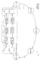
- FIG. 1 A block diagram illustrating an example prior art optical ring network comprising a plurality of nodes is shown in FIG. 1 .
- the optical network generally referenced 10 , comprises a plurality of nodes 12 , labeled node #1 through #5, connected by optical fiber links 14 so as to form an optical ring network.
- the ring network is characterized by communications that take place from node to node. In this example network, only a single ring is shown such that communications proceeds in the clockwise direction only.
- a second ring can be implemented that carries communications between nodes in the opposite or counter-clockwise direction.
- Wavelength division multiplexed (WDM) optical networks are particularly desirable because of their restoration capabilities and suitability for minimizing the optical fiber length for the interconnection of system nodes.
- a typical WDM optical ring network includes network elements with optical add/drop multiplexers (OADMs), whereby some optical channels are dropped, some are added and/or other channels are expressed or passed through.
- OADMs optical add/drop multiplexers
- each ring node is connected to exactly two other ring nodes.
- the OADMs are used to construct a ring network whereby adjacent OADMs are connected pair wise while the network nodes are situated to form a ring.
- any node can be reached from any other node using two physically separate paths, i.e. one traveling clockwise and the other counter clockwise.
- the opposite traveling paths are used to provide protection against route failures.
- the use of at least two parallel fibers with traffic flowing in opposite directions provides restoration capabilities in the event of a fiber cut.
- An Add/Drop Optical Multiplexer functions to filter or drop one or more wavelengths transmitted on the ring.
- the optical technologies typically used for producing an ADOM can be placed in two main categories, namely: (1) those using fixed filtering, whereby an ADOM is produced for dropping and adding a fixed wavelength, and (2) those using tunable filtering, whereby an external control determines the wavelength of the dropped and added channel.
- OADMs optical add/drop multiplexers
- FIG. 2A A block diagram illustrating a typical structure of an Optical Add/Drop Multiplexer (OADM) is shown in FIG. 2A .
- the OADM generally referenced 20 , comprises drop module 22 adapted to generate a drop channel 26 from the multi-wavelength input signal and an add module 24 , incorporating an optical amplifier 23 , adapted to add a channel 28 to the multi-wavelength output signal.
- a problem associated with such types of optical networks is the losses incurred from the passive optical devices, such as filters, couplers, multiplexers, etc.
- the losses, which exist at every node on the network, can increase as the number of optical components increases, such as in networks with large numbers of nodes,
- optical amplifiers are used along the optical ring to boost the weak optical signals.
- Commonly used optical amplifiers include Erbium Doped Fiber Amplifiers (EDFAs).
- EDFAs Erbium Doped Fiber Amplifiers
- the use of optical amplifiers, however, is problematic.
- the amplifiers function to boost not only the optical signals but also any noise present.
- the optical amplifiers add noise to the line in addition to the signal and to the noise already present.
- noise creep In non-ring type networks, techniques are well known for reducing the effects of the noise.
- an optical ring network In an optical ring network, however, the use of active optical amplifiers causes noise accumulation from amplifier spontaneous emissions (ASE) and from other noise sources as well, and is commonly referred to as noise creep.
- ASE amplifier spontaneous emissions
- FIGS. 2B through 2G Signal graphs illustrating the phenomena of ASE and noise build up or amplifier noise accumulation are shown in FIGS. 2B through 2G .
- the graphs correspond to points A, B and C shown in FIG. 2A .
- Each node along the ring employs at least one OADM 20 .
- FIGS. 2B , 2 C and 2 D correspond to the baseline optical signal levels along the ring at points A, B and C, respectively.
- FIGS. 2E , 2 F and 2 G correspond to the optical signal levels after a complete revolution around the ring at points A, B and C, respectively.
- the relative amplitude is plotted as a function of frequency (i.e. wavelength).
- the five peaks 30 in relative amplitude correspond to five different wavelengths in use along the ring.
- the OADM 20 corresponds to the lowest frequency.
- the add module employs an active amplifier to boost the optical signal with the new channel added.
- the signal at point C comprises the five wavelengths amplified.
- the noise level is also amplified by an amount ⁇ N 1 where N represents the noise added to the signal each loop around the ring.
- FIG. 2E illustrates the optical signal at the same point A after traversing the loop.
- the wavelength peaks are present along with an elevated noise floor.
- the original signal as shown in FIG. 2B is indicated by dotted line 34 .
- the first wavelength is removed as shown in FIG. 2F .
- a channel is then added and the resulting signal amplified as shown in FIG. 2G .
- the noise along with the signal is amplified.
- the noise level also rises by an additional amount ⁇ N 2 to a level indicated by line 38 .
- the noise level at point C from the previous loop is indicated by line 36 while the original noise level at point A is indicated by line 34 .
- the noise level has increased to a level equal to ⁇ N 1 + ⁇ N 2 .
- the effects of noise creep can amount to significant levels of noise after only relatively few trips around the ring.
- the noise caused by amplifier noise and other noise source accumulation increases sufficiently to saturate the amplifier and communications along the optical ring becomes impossible.
- FIG. 3 A block diagram illustrating a prior art optical ring network that attempts to solve the amplifier noise accumulation problem is shown in FIG. 3 .
- the example network generally referenced 40 , comprises five nodes 42 , labeled node #1 through node #5, connected by link 48 .
- the link between nodes #1 and #5 is severed leaving two stubs 46 , 44 .
- the problem of noise creep is eliminated since the optical signal begins and terminates within a single rotation.
- a disadvantage of this solution is that the ring properties of the network are destroyed. Communications around the ring can only take place in one direction. Thus, one half of the bandwidth is lost. For example, in a closed ring, two nodes normally can communication with each other in two directions, clockwise and counter-clockwise directions of communications.
- the network 40 only supports unidirectional communications. Bi-directional communications is a very desirable characteristic and a major benefit of employing optical networks in ring configuration.
- a solution to this is to normally maintain the ring in an open state and to close it only when necessary such as during a fiber cut or other failure along the ring. This requires adding means to the network operative to detect fiber cuts and to close the ring in response thereto.
- FIG. 4 A block diagram illustrating a prior art Optical Electrical Optical (OEO) termination module is shown in FIG. 4 .
- the network generally referenced 50 , comprises a plurality of nodes 52 , labeled node #1 through node #N, connected by optical links 54 .
- the ring is broken and an Optical/Electrical/Optical (OEO) termination is inserted.
- the OEO terminator comprises an optical demultiplexer 56 , optical multiplexer 64 , optical to electrical converters 58 , electrical repeaters 60 and electrical to optical converters 62 .
- the optical signal received by the demultiplexer is divided into N optical signals 57 each having a different wavelength. Each individual channel is then converted from the optical domain to the electrical domain by optical to electrical converter 58 to yield an electrical signal 66 .
- the electrical signal is then amplified and regenerated to yield a regenerated electrical signal 68 .
- This signal is then converted to an optical signal 70 by electrical to optical converter 62 .
- the optical signals output from the N converters 62 are multiplexed by multiplexer 64 into a composite multi-wavelength optical signal that is then transmitted to the first node on the ring.
- a benefit of electrical regeneration of the signal is that the noise is cleaned from the ring.
- each individual channel is accessible electrically for any purpose.
- a disadvantage of this solution is that it is relatively costly in terms of complexity and the requirement to add optical and electrical based hardware to the ring.
- the electrical based equipment must be managed, adding to the cost and complexity.
- the equipment typically consumes a large amount of space. Further, the use of additional electrical equipment lowers the overall reliability of the network as it is another potential point of failure.
- the present invention comprises an optical network terminator for terminating an optical network.
- the invention is applicable to optical networks having any kind of topology such as optical ring networks, point-to-point networks, mesh networks, star networks, etc.
- the invention comprises a filter that can be implemented using any suitable technology such as multiplexer/demultiplexer, Fiber Bragg Grating (FBG) based filters, etc.
- FBG Fiber Bragg Grating
- the invention is not limited to the type of wavelength content.
- the optical network may implement Dense Wavelength Division Multiplexing (DWDM), WDM, Coarse Wavelength Division Multiplexing (CWDM), Wide Wavelength Division Multiplexing (WWDM), etc., a specific wavelength or can be any type of non-WDM based network.
- Use of the present invention eliminates the prior art problems of noise accumulation regardless of its source, such as Amplifier Spontaneous Emission (ASE) noise, thermal noise, noise due to non-linear effects, etc.
- ASE Amplifier Spontaneous
- the invention is described in the context of an optical ring network. It is appreciated that the invention is not limited to the example optical networks presented but can be applied to any type of optical network.
- optical terminator is operative to overcome the problems associated with the prior art by breaking the link between two nodes and placing an optical noise filtering mechanism, termed an ‘optical network terminator,’ therebetween.
- an optical network terminator For example, in the case of an optical ring network, the invention breaks the ring and places the optical terminator between two nodes.
- the ‘optical terminator’ denotes any suitable filtering mechanism including but not limited to an optical demultiplexer coupled to an optical multiplexer, optical add/drop multiplexer, Fiber Bragg Gratings, polarization based devices, etc. It is appreciated, however, that other types of optical filtering schemes may be used without departing from the scope of the invention.
- the ‘optical terminator’ functions to filter each individual wavelength of light and generate a multi-wavelength optical output with the accumulation of noise removed, including amplifier noise.
- the filtering out of the noise accumulation occurs in the optical domain without the need for optical to electrical and electrical to optical conversion.
- the filter e.g., combination of optical demultiplexer and multiplexer (or any other optical filtering method), functions to pass for each channel a ‘cleaned’ signal wherein the noise has been removed.
- the invention also provides a means to add optical features to a system in a seamless manner.
- Features such as equalizing the optical power between WDM channels. Equalization of the channels is achieved by placing variable optical attenuators and monitors in line with each channel.
- the invention also enables the remote disconnection from the ring of channels currently not in use. Disconnecting unused channels aids in reducing cross talk between channels. A channel is disconnected by reducing the gain of the corresponding attenuator sufficiently such that the channel is effectively removed from the optical ring.
- a method of optical network termination in an optical network having one or more channels each potentially corrupted with noise comprising the steps of receiving one or more input optical signals transmitted over the one or more channels of the optical network, filtering the one or more input optical signals so as to remove any accumulated noise and outputting the output optical signal onto the one or more channels on the optical network.
- an optical network terminator for terminating an optical network comprising a receiver for receiving one or more multi-channel optical input signals, an optical demultiplexer operative to demultiplex each the input multi-channel optical signal into a plurality of individual optical channels, each the optical channel having a unique wavelength, an optical multiplexer operative to multiplex the plurality of individual optical channels so as to generate one or more output multi-channel optical signals with any accumulated noise removed and a transmitter for outputting the one or more output multi-channel optical signals.
- an optical network comprising a plurality of nodes, wherein a portion of the nodes employs one or more optical amplifiers, an optical network terminator for terminating the optical network, wherein the optical network terminator comprises one or more optical receiving ports for receiving input single or multi-channel optical signals, an optical demultiplexer operative to demultiplex each the input multi-channel optical signals into a plurality of individual optical channels, each the optical channel having a unique wavelength, an optical multiplexer operative to multiplex the plurality of individual optical channels so as to generate an output multi-channel optical signal with any noise accumulation removed and one or more optical transmitting ports adapted to output the output single or multi-channel optical signal.
- an optical ring network comprising a plurality of nodes situated around the optical ring, wherein a portion of the nodes employs one or more optical amplifiers, an optical network terminator for terminating the optical ring network, wherein the optical network terminator comprises an optical receiver for receiving an input multi-channel optical signal, an optical demultiplexer operative to demultiplex the input multi-channel optical signal into a plurality of individual optical channels, each the optical channel having a unique wavelength, a plurality of optical attenuators, each optical attenuator coupled in-line to an individual optical channel, the optical attenuator operative to very the optical gain of an optical signal, a plurality of monitors, each monitor coupled in-line to an individual optical channel, the monitor operative to measure the optical power of an optical signal, an optical multiplexer operative to multiplex the plurality of individual optical channels so as to generate an output multi-channel optical signal with any noise accumulation removed and an optical transmitter adapted to output the output multi-channel optical signal.
- a method of optically terminating an optical network having one or more channels comprising the steps of receiving an input optical signal containing a single channel and having wavelength associated therewith, filtering the input optical signal to remove unwanted noise and to generate an output optical signal therefrom and outputting the output optical signal.
- FIG. 1 is a block diagram illustrating an example prior art optical ring network comprising a plurality of nodes
- FIG. 2A is a block diagram illustrating a typical structure of an Optical Add/Drop Multiplexer (OADM);
- OADM Optical Add/Drop Multiplexer
- FIGS. 2B through 2G are signal graphs illustrating the phenomenon of amplifier noise accumulation
- FIG. 3 is a block diagram illustrating a prior art optical ring network that attempts to solve the amplifier noise accumulation problem
- FIG. 4 is a block diagram illustrating a prior art Optical Electrical Optical (OEO) termination module
- FIG. 5 is a block diagram illustrating an example optical network employing the optical network terminator constructed in accordance with the present invention
- FIG. 6 is a block diagram illustrating an example optical ring network employing the optical network terminator constructed in accordance with the present invention
- FIG. 7A is a block diagram illustrating the optical network terminator of the present invention with several optical signal points identified;
- FIGS. 7B through 7D are signal graphs illustrating the elimination of amplifier noise accumulation using the optical network terminator of the present invention.
- FIG. 8 is a block diagram illustrating the optical network terminator of the present invention adapted to provide gain equalization, monitoring and remote enable/disable capabilities.
- the present invention comprises an optical network terminator for terminating an optical network and removing unwanted noise accumulation.
- the invention is applicable to optical networks having any kind of physical or logical topology such as optical ring networks, point-to-point networks, mesh networks, star networks, etc.
- optical networks having any kind of physical or logical topology
- point-to-point networks such as optical ring networks, point-to-point networks, mesh networks, star networks, etc.
- mesh type networks may comprise one or more sub-rings wherein each sub-ring comprises an optical terminator of the present invention.
- the invention comprises a terminator that can be implemented using any suitable technology such as multiplexer/demultiplexer combination, Fiber Bragg Grating (FBG) based filters, Optical Band Pass Filters (OBPFs), filters based on polarization based devices, etc.
- FBG Fiber Bragg Grating
- OBPFs Optical Band Pass Filters
- the optical network may implement Dense Wavelength Division Multiplexing (DWDM), WDM, CWDM, WWDM, etc., a specific wavelength or can be any type of non-WDM network as well.
- DWDM Dense Wavelength Division Multiplexing
- WDM Wideband Division Multiplexing
- CWDM Wideband Division Multiplexing
- WWDM Worldwide Interoperability for Microwavelength Division Multiplexing
- Use of the present invention eliminates the prior art problems of noise accumulation regardless of its source, such as Amplifier Spontaneous Emission (ASE) noise, thermal noise, noise due to non-linear effects, etc.
- ASE Amplifier Spontan
- the invention is described in the context of a multi-channel optical ring network. It is appreciated that the invention is not limited to the example optical networks presented but can be applied to any type of physical optical network that is adapted to implement any type of logical network, e.g., star, mesh, etc.
- a ring network may be adapted to implement a star or mesh network by appropriately configuring the nodes and transmission wavelength assignments.
- the example network described herein employs a plurality of nodes wherein each node employs one or more OADMs, each corresponding to a single wavelength.
- the network also employs optical amplifiers such as Erbium Doped Fiber Amplifiers (EDFAs), for example.
- EDFAs Erbium Doped Fiber Amplifiers
- add drop multiplexer denotes transmission equipment that functions to add and drop information from an optical ring to and from one or more switching elements.
- optical ring network any type of topology comprising any number of nodes and OADMs, any type of optical amplifiers and any type of noise (i.e. undesirable optical signal).
- the invention is not limited to optical ring type networks but can be applied to other types of networks as well. It is not intended that the invention be limited to the configurations and example embodiments described herein. It is appreciated that one skilled in the art may apply the principles of the present invention to numerous other types of optical network configurations without departing from the spirit and scope of the invention.
- the invention overcomes the problems associated with the prior art by virtually breaking the ring and virtually placing an optical terminator in line with the optical signal. It is important to note that in contrast to prior art electronic ring termination which is a physical termination, the optical network termination of the present invention is a logical termination only since the signal remains in the optical domain and is not converted to the electrical domain.
- FIG. 5 A block diagram illustrating an example optical network employing the optical network terminator constructed in accordance with the present invention is shown in FIG. 5 .
- the optical network generally referenced 130 , comprises a plurality of nodes 132 , labeled node #1 through node #N, connected by optical links 134 .
- the optical network is virtually broken and an optical network terminator 136 is virtually placed in line with the signal. Note that the particular location of virtually breaking the network is not critical to the operation of the invention.
- the ‘optical terminator’ 136 comprises an M channel optical filter 138 .
- the optical terminator functions to remove amplifier spontaneous emissions (ASE) noise, thermal noise, noise due to non-linearities, etc. and any other type of noise by filtering the optical signal.
- ASE amplifier spontaneous emissions
- thermal noise thermal noise
- each individual wavelength of light is filtered and a multi-wavelength optical output is generated with the noise accumulation removed.
- the cleaned optical signals are then output as a multi-wavelength output signal.
- the filter may comprise a demultiplexer/multiplexer combination, wavelength selective coupler, Optical Add/Drop Multiplexer, Fiber Bragg Gratings (FBG) based filter, polarization devices such as wideband isolators that can isolate a particular wavelength, a filter implemented using polarization, etc.
- FBG Fiber Bragg Gratings
- An FBG based optical filter suitable for use with the present invention is Part Number FBG-ITU-99-0.8S, manufactured by Innovative Fibers Inc., Gatineau, Quebec, Canada. Note that a plurality of FBG based filters, each adapted to filter a particular wavelength, can be cascaded in parallel or placed in series combination so as to cover multiple wavelengths.
- optical filters suitable for use with the present invention include a fiber Fabry-Perot optical filter, Part Number FFP-TF, manufactured by Micron Optics Inc., Atlanta, Ga.; a Mach-Zehnder optical filter, AmpFlat Part Number AFF-1550-ABC99-0, manufactured by Photonic Technologies, Eveleigh, Australia; Acousto-Optic-Tunable-Filter, Infrared Fiber Optics—AOTF.
- a polarization based filter suitable for use with the present invention is the PolarWave Optical Slicer 50G Filter manufactured by Chorum Technologies, Richardson, Tex.
- the filter functions to only pass for each channel a band limited signal around the center frequency corresponding to the wavelengths supported by the particular network.
- An important aspect of the invention is that the filtering out of the noise accumulation occurs in the optical domain without the need for optical to electrical converters, electrical repeaters and electrical to optical conversion.
- the terminator may be constructed to handle any number M of channels using a suitably adapted filter.
- FIG. 6 A block diagram illustrating an example optical ring network employing the optical network terminator constructed in accordance with the present invention is shown in FIG. 6 .
- the optical ring network generally referenced 80 , comprises a plurality of nodes 82 , labeled node #1 through node #N, connected by optical links 84 .
- the optical ring is virtually broken and an optical based network terminator 86 is virtually placed in line with the signal. Note that the particular location of virtually breaking the ring is not critical to the operation of the invention.
- the optical network terminator 86 comprises an M output optical demultiplexer 88 coupled to an M input optical multiplexer 92 via a plurality of optical cables 90 .
- the optical network terminator functions to remove the amplifier spontaneous emissions (ASE) noise and any other type of noise by filtering the optical signal. Each individual wavelength of light is filtered and a multi-wavelength optical output is generated with the amplifier noise accumulation and/or any other type of noise removed. The cleaned optical signals are then multiplexed to generate a multi-wavelength output signal.
- ASE amplifier spontaneous emissions
- the demultiplexer and multiplexer can be replaced with a filter that performs the same filtering function. Any suitable filtering mechanism may be used as long as it is effective to remove the ASE and other types of noise.
- optical demultiplexer and multiplexer functions for each channel to only pass a band limited signal around the center frequency corresponding to the DWDM wavelengths supported by the particular ring network.
- the filtering out of the noise accumulation occurs in the optical domain without the need for optical to electrical converters, electrical repeaters and electrical to optical conversion.
- optical network terminator may be constructed to handle any number M of channels using either single or multiple pairs of demultiplexers and multiplexers.
- devices other than optical demultiplexers can be employed to perform the optical filtering function, such as ADOM, FBG, OBPF, polarization based isolators and filters, etc.
- FIG. 7A A block diagram illustrating the optical network terminator of the present invention with several optical signal points identified is shown in FIG. 7A .
- the optical network terminator generally referenced 100 , comprises an M output demultiplexer 102 and M input multiplexer 104 connected to each other by optical fiber cables 106 .
- FIGS. 7B through 7D Signal graphs illustrating the elimination of amplifier noise accumulation using the optical network terminator of the present invention are shown in FIGS. 7B through 7D .
- FIGS. 7B , 7 C and 7 D correspond to the signal present at points A, B and C, respectively, shown in FIG. 7A .
- FIG. 7B illustrates the multi-channel signal input to the demultiplexer 102 .
- Each peak 108 in relative amplitude corresponds to a unique DWDM wavelength in use along the ring.
- the demultiplexer 102 functions to filter out all but a single wavelength from the input signal.
- FIG. 7C wherein all but a single peak 110 is filtered from the input.
- the optical demultiplexer is operative to only pass for each channel a band limited signal around the center frequency corresponding to a particular DWDM wavelength.
- the optical demultiplexer functions to remove the ASE noise, thermal noise, effects due to non-linearities, etc. and any other applicable noise from the optical ring.
- the multiplexer 104 functions to combine the M channels into a single multi-channel output signal as shown in FIG. 7D .
- Each individual channel 112 comprises a band-limited signal with the amplifier noise accumulation filtered out.
- the invention also comprises additional embodiments that provide additional functionality such as line equalization, line monitoring and remote line disconnection, as described in more detail hereinbelow.
- FIG. 8 A block diagram illustrating the optical network terminator of the present invention adapted to provide gain equalization, a monitoring and remote enable/disable capability is shown in FIG. 8 .
- the modified optical network terminator generally referenced 110 , comprises a demultiplexer 114 and multiplexer 120 as in the first embodiment of FIG. 6 , but also comprises additional components to enable functions such as line equalization, line monitoring and remote line disconnection.
- the optical network terminator 110 comprises a plurality of optical attenuators 116 adapted to have variable levels of attenuation that can be controlled electrically, a plurality of line monitors 118 and a controller 122 .
- a means for equalizing the optical power of each channel is provided. Equalization of the channels is achieved using the variable optical attenuators 116 and monitors 118 placed in line with each channel.
- the attenuators 116 are controlled by the controller 122 .
- the controller is adapted to generate an input to each attenuator for setting the attenuation level.
- the measurement output of each monitor 118 is input to the controller 122 .
- the controller comprises a processor or central processing unit (CPU) such as a digital signal processor (DSP), microcontroller, microprocessor or microcomputer and static read only memory (ROM) and dynamic main memory or random access memory (RAM) all in communication with the processor.
- CPU central processing unit
- DSP digital signal processor
- ROM read only memory
- RAM dynamic main memory or random access memory
- the processor is also in communication, via suitable control and data lines, with the plurality of attenuator and line monitors.
- the controller 122 is adapted to control and maintain the operation of the system optical network terminator.
- the control may also comprise a magnetic storage device for storing application programs and data.
- the system may also comprise a computer readable storage medium, which may include any suitable memory means including but not limited to magnetic storage, optical storage, semiconductor volatile or non-volatile memory, biological memory devices, or any other memory storage device.
- the optical network terminator is adapted to perform line equalization whereby the power level of each channel is measured using the channel monitor and any adjustments are made via the attenuator associated with that channel.
- Line monitoring can also be performed without equalization, where it is required to obtain optical power measurements of all channels.
- channel monitoring can also be performed without equalization, where it is required to obtain optical power measurements of one or more channels.
- the invention also enables the remote disconnection of one or more channels from the optical ring.
- An optical channel is ‘disconnected’ from the ring by increasing the attenuation of its corresponding attenuator high enough such that the channel is effectively removed from the ring. Removing unused channels helps to reduce the associated noise and the cross talk between the channels that are in use on the ring.
- the ability to remove a channel remotely is realized using the ability to set the level of attenuation of the attenuators electrically.
- the present invention enables the removal of unused channels remotely, such as from a central management center 123 employed to monitor and control one or more optical ring networks.
- the controller is programmed with suitable software that is constructed to perform the line equalization, line/channel monitoring and remote channel(s) disconnect method of the present invention.
- the controller software is adapted to reside on a computer readable medium, such as a magnetic disk within a disk drive unit, e.g., hard disk drive media, floppy drive media, etc.
- the computer readable medium may comprise a floppy disk, Flash memory card, EEROM based memory, bubble memory storage, ROM storage, RAM storage, etc.
- the controller software may also reside, in whole or in part, in the static or dynamic main memories or in firmware within the processor of the computer system (i.e. within microcontroller, microprocessor or microcomputer internal memory).
- the method of the present invention may be applicable to implementations of the invention in integrated circuits, field programmable gate arrays (FPGAs), chip sets or application specific integrated circuits (ASICs), wireless implementations and other communication system products.
- FPGAs field programmable gate arrays
- ASICs application specific integrated circuits
- any of the optical demultiplexer and multiplexer types used in the optical network terminator have similar optical characteristics as the optical components used in the multiplexers (add/drop or otherwise) within the nodes along the ring.
Abstract
Description
| The following notation is used throughout this document. |
| Term | Definition | ||
| ADOM | Add Drop Optical Multiplexer | ||
| ASE | Amplifier Spontaneous Emission | ||
| ASIC | Application Specific Integrated Circuit | ||
| CPU | Central Processing Unit | ||
| DSP | Digital Signal Processor | ||
| WWDM | Wide Wavelength Division Multiplexing | ||
| CWDM | Coarse Wavelength Division Multiplexing | ||
| DWDM | Dense Wavelength Division Multiplexing | ||
| EDFA | Erbium Doped Fiber Amplifiers | ||
| EEROM | Electrically Erasable Read Only Memory | ||
| FBG | Fiber Bragg Grating | ||
| FPGA | Field Programmable Gate Array | ||
| IP | Internet Protocol | ||
| LAN | Local Area Network | ||
| MAN | Metropolitan Area Network | ||
| OADM | Optical Add Drop Multiplexer | ||
| OBPF | Optical Band Pass Filter | ||
| OEO | Optical Electrical Optical | ||
| RAM | Random Access Memory | ||
| ROM | Read Only Memory | ||
| WAN | Wide Area Network | ||
| WDM | Wavelength Division Multiplexing | ||
Claims (8)
Priority Applications (1)
| Application Number | Priority Date | Filing Date | Title |
|---|---|---|---|
| US09/781,461 US7106969B1 (en) | 2001-02-12 | 2001-02-12 | Optical network terminator |
Applications Claiming Priority (1)
| Application Number | Priority Date | Filing Date | Title |
|---|---|---|---|
| US09/781,461 US7106969B1 (en) | 2001-02-12 | 2001-02-12 | Optical network terminator |
Publications (1)
| Publication Number | Publication Date |
|---|---|
| US7106969B1 true US7106969B1 (en) | 2006-09-12 |
Family
ID=36951888
Family Applications (1)
| Application Number | Title | Priority Date | Filing Date |
|---|---|---|---|
| US09/781,461 Expired - Lifetime US7106969B1 (en) | 2001-02-12 | 2001-02-12 | Optical network terminator |
Country Status (1)
| Country | Link |
|---|---|
| US (1) | US7106969B1 (en) |
Cited By (30)
| Publication number | Priority date | Publication date | Assignee | Title |
|---|---|---|---|---|
| US20030151789A1 (en) * | 2001-11-15 | 2003-08-14 | Alcatel Optronics France | Method of dynamically controlling an optical module |
| US20040120711A1 (en) * | 2001-03-20 | 2004-06-24 | Elbers Joerg-Peters | Optical transmission system with variable network limits |
| US20050008363A1 (en) * | 2003-07-08 | 2005-01-13 | Fujitsu Network Communications, Inc. | Method and system for management of directly connected optical components |
| US20050036790A1 (en) * | 2002-03-19 | 2005-02-17 | Fujitsu Limited | Method and system for optical fiber transmission using Raman amplification |
| US20050041978A1 (en) * | 2001-10-03 | 2005-02-24 | Rajeev Roy | Optical signal to noise ratio system |
| US20050117907A1 (en) * | 2002-01-04 | 2005-06-02 | Claringburn Harry R. | Noise reduction in optical communications networks |
| US20050185960A1 (en) * | 2004-02-23 | 2005-08-25 | Alcatel | Optical ring transmission network |
| US20050286905A1 (en) * | 2004-06-25 | 2005-12-29 | Mohs Georg H | Optical fiber transmission system with noise loading |
| US20060023996A1 (en) * | 2004-07-30 | 2006-02-02 | Fujitsu Limited | Optical add/drop multiplexer |
| US20060050751A1 (en) * | 2004-09-06 | 2006-03-09 | Fujitsu Limited | Optical transmission device for controlling optical level of wavelength multiplexed light and method thereof |
| US20070031146A1 (en) * | 2000-02-21 | 2007-02-08 | Nippon Telegraph And Telephone Corporation | Node apparatus, optical wavelength division multiplexing network, and system switching method |
| US20070201878A1 (en) * | 2006-02-28 | 2007-08-30 | Fujitsu Limited | Repeater and repeating method |
| US7502568B1 (en) * | 2003-12-04 | 2009-03-10 | National Semiconductor Corporation | Method of using low bandwidth sensor for measuring high frequency AC modulation amplitude |
| US7630422B1 (en) | 2005-01-14 | 2009-12-08 | National Semiconductor Corporation | Driver for vertical-cavity surface-emitting laser and method |
| US20100008672A1 (en) * | 2008-07-09 | 2010-01-14 | Tyco Telecommunications (Us) Inc. | Optical Add/Drop Multiplexer Including Reconfigurable Filters and System Including the Same |
| US7680032B1 (en) * | 2003-12-19 | 2010-03-16 | Ciena Corporation | Bidirectional line switched partial rings, mesh networks, and methods of operation |
| WO2011058547A1 (en) | 2009-11-12 | 2011-05-19 | Eci Telecom Ltd. | Optical communication network having flexible operability |
| US20150229399A1 (en) * | 2007-08-27 | 2015-08-13 | Fujitsu Limited | Network management system |
| US20180212706A1 (en) * | 2017-01-20 | 2018-07-26 | Cox Communications, Inc. | Optical comunications module link, systems, and methods |
| US20190037286A1 (en) * | 2017-01-20 | 2019-01-31 | Cox Communications Inc. | Coherent gigabit ethernet and passive optical network coexistence in optical communications module link extender related systems and methods |
| US10993003B2 (en) | 2019-02-05 | 2021-04-27 | Cox Communications, Inc. | Forty channel optical communications module link extender related systems and methods |
| US10997041B2 (en) | 2018-04-25 | 2021-05-04 | Hewlett Packard Enterprise Development Lp | Method to disable or reboot unresponsive device with active uplink in a ring network |
| US10999658B2 (en) | 2019-09-12 | 2021-05-04 | Cox Communications, Inc. | Optical communications module link extender backhaul systems and methods |
| US11146350B1 (en) | 2020-11-17 | 2021-10-12 | Cox Communications, Inc. | C and L band optical communications module link extender, and related systems and methods |
| US11271670B1 (en) | 2020-11-17 | 2022-03-08 | Cox Communications, Inc. | C and L band optical communications module link extender, and related systems and methods |
| US11317177B2 (en) | 2020-03-10 | 2022-04-26 | Cox Communications, Inc. | Optical communications module link extender, and related systems and methods |
| US11323788B1 (en) | 2021-02-12 | 2022-05-03 | Cox Communications, Inc. | Amplification module |
| US11502770B2 (en) | 2017-01-20 | 2022-11-15 | Cox Communications, Inc. | Optical communications module link extender, and related systems and methods |
| US11523193B2 (en) | 2021-02-12 | 2022-12-06 | Cox Communications, Inc. | Optical communications module link extender including ethernet and PON amplification |
| US11689287B2 (en) | 2021-02-12 | 2023-06-27 | Cox Communications, Inc. | Optical communications module link extender including ethernet and PON amplification |
Citations (25)
| Publication number | Priority date | Publication date | Assignee | Title |
|---|---|---|---|---|
| US5612805A (en) * | 1994-06-07 | 1997-03-18 | Alcatel Cit | Add-drop optical spectrum-division multiplexer |
| US5812710A (en) * | 1996-02-07 | 1998-09-22 | Fujitsu Limited | Apparatus and method for optical equalization and amplification |
| US5986800A (en) * | 1995-04-05 | 1999-11-16 | Hitachi, Ltd. | Optical amplification apparatus |
| US6067187A (en) * | 1995-11-29 | 2000-05-23 | Fujitsu Limited | Optical amplifier and optical communication system employing the same |
| US6226425B1 (en) * | 1999-02-24 | 2001-05-01 | Bandwidth9 | Flexible optical multiplexer |
| US6262835B1 (en) * | 1996-11-25 | 2001-07-17 | Hitachi, Ltd | Optical amplifier unit control methods, optical amplifier systems and systems which use the methods and amplifier systems |
| US6321003B1 (en) * | 1999-06-04 | 2001-11-20 | Bandwidth9, Inc. | Tunable semiconductor laser system |
| US6344910B1 (en) * | 1999-09-23 | 2002-02-05 | Avanex Corporation | Optical performance monitor |
| US6356386B1 (en) * | 2000-02-29 | 2002-03-12 | Lucent Technologies Inc. | Method and apparatus for stabilizing transient control in amplified optical networks |
| US6359726B1 (en) * | 1999-03-02 | 2002-03-19 | Fujitsu Limited | Wavelength division multiplexing optical amplifier with function of gain-equalizing and optical communication system |
| US6366379B1 (en) * | 1998-01-30 | 2002-04-02 | Fujitsu Limited | Remote control device of acousto-optic tunable filter and optical transmission system containing equalizer using acousto-optic tunable filter and optical transmission system containing optical add/drop multiplexer using acousto-optic tunable filter |
| US6400498B1 (en) * | 1997-05-29 | 2002-06-04 | Nec Corporation | Optical signal repeating and amplifying device and optical level adjusting device |
| US6466348B1 (en) * | 1998-03-11 | 2002-10-15 | Fujitsu Limited | Trunk apparatus of a wavelength-division-multiplexing communication system for controlling a gain of an optical amplifier provided therein |
| US6483636B1 (en) * | 1999-10-18 | 2002-11-19 | Fujitsu Limited | Optical amplifier |
| US6496619B2 (en) * | 1999-01-18 | 2002-12-17 | Fujitsu Limited | Method for gain equalization, and device and system for use in carrying out the method |
| US6515777B1 (en) * | 1999-03-12 | 2003-02-04 | Marconi Communications Limited | Ring gain control in WDM optical signal transmission system |
| US6519060B1 (en) * | 1999-06-04 | 2003-02-11 | Chorum Technologies Lp | Synchronous optical network in frequency domain |
| US6529317B2 (en) * | 2000-06-08 | 2003-03-04 | Electronics And Telecommunications Research Institute | L-band erbium-doped fiber amplifier pumped by 1530 nm-band pump |
| US6549314B1 (en) * | 1998-11-02 | 2003-04-15 | Nec Corporation | Optical control apparatus, optical junction apparatus, optical ADM apparatus and optical transmission apparatus having thereof |
| US6580550B1 (en) * | 1999-07-06 | 2003-06-17 | Hitachi, Ltd. | Filter with variable transmission character, optical transmission equipment and method of optical transmission |
| US6594046B1 (en) * | 1998-05-11 | 2003-07-15 | Nec Corporation | Level-flattening circuit for WDM optical signals |
| US6624926B1 (en) * | 2000-08-25 | 2003-09-23 | Fujitsu Limited | Optical amplifier with pump light source control for raman amplification |
| US6626590B1 (en) * | 1998-12-08 | 2003-09-30 | Nippon Telegraph And Telephone Corporation | Optical communication network |
| US6643055B1 (en) * | 1997-10-21 | 2003-11-04 | Tomas Askinger | Optical amplifier control |
| US6646795B1 (en) * | 2000-11-20 | 2003-11-11 | Nortel Networks Limited | Optical amplifier |
-
2001
- 2001-02-12 US US09/781,461 patent/US7106969B1/en not_active Expired - Lifetime
Patent Citations (26)
| Publication number | Priority date | Publication date | Assignee | Title |
|---|---|---|---|---|
| US5612805A (en) * | 1994-06-07 | 1997-03-18 | Alcatel Cit | Add-drop optical spectrum-division multiplexer |
| US5986800A (en) * | 1995-04-05 | 1999-11-16 | Hitachi, Ltd. | Optical amplification apparatus |
| US6094296A (en) * | 1995-04-05 | 2000-07-25 | Hitachi, Ltd. | Optical amplification apparatus |
| US6067187A (en) * | 1995-11-29 | 2000-05-23 | Fujitsu Limited | Optical amplifier and optical communication system employing the same |
| US5812710A (en) * | 1996-02-07 | 1998-09-22 | Fujitsu Limited | Apparatus and method for optical equalization and amplification |
| US6262835B1 (en) * | 1996-11-25 | 2001-07-17 | Hitachi, Ltd | Optical amplifier unit control methods, optical amplifier systems and systems which use the methods and amplifier systems |
| US6400498B1 (en) * | 1997-05-29 | 2002-06-04 | Nec Corporation | Optical signal repeating and amplifying device and optical level adjusting device |
| US6643055B1 (en) * | 1997-10-21 | 2003-11-04 | Tomas Askinger | Optical amplifier control |
| US6366379B1 (en) * | 1998-01-30 | 2002-04-02 | Fujitsu Limited | Remote control device of acousto-optic tunable filter and optical transmission system containing equalizer using acousto-optic tunable filter and optical transmission system containing optical add/drop multiplexer using acousto-optic tunable filter |
| US6466348B1 (en) * | 1998-03-11 | 2002-10-15 | Fujitsu Limited | Trunk apparatus of a wavelength-division-multiplexing communication system for controlling a gain of an optical amplifier provided therein |
| US6594046B1 (en) * | 1998-05-11 | 2003-07-15 | Nec Corporation | Level-flattening circuit for WDM optical signals |
| US6549314B1 (en) * | 1998-11-02 | 2003-04-15 | Nec Corporation | Optical control apparatus, optical junction apparatus, optical ADM apparatus and optical transmission apparatus having thereof |
| US6626590B1 (en) * | 1998-12-08 | 2003-09-30 | Nippon Telegraph And Telephone Corporation | Optical communication network |
| US6496619B2 (en) * | 1999-01-18 | 2002-12-17 | Fujitsu Limited | Method for gain equalization, and device and system for use in carrying out the method |
| US6226425B1 (en) * | 1999-02-24 | 2001-05-01 | Bandwidth9 | Flexible optical multiplexer |
| US6359726B1 (en) * | 1999-03-02 | 2002-03-19 | Fujitsu Limited | Wavelength division multiplexing optical amplifier with function of gain-equalizing and optical communication system |
| US6515777B1 (en) * | 1999-03-12 | 2003-02-04 | Marconi Communications Limited | Ring gain control in WDM optical signal transmission system |
| US6519060B1 (en) * | 1999-06-04 | 2003-02-11 | Chorum Technologies Lp | Synchronous optical network in frequency domain |
| US6321003B1 (en) * | 1999-06-04 | 2001-11-20 | Bandwidth9, Inc. | Tunable semiconductor laser system |
| US6580550B1 (en) * | 1999-07-06 | 2003-06-17 | Hitachi, Ltd. | Filter with variable transmission character, optical transmission equipment and method of optical transmission |
| US6344910B1 (en) * | 1999-09-23 | 2002-02-05 | Avanex Corporation | Optical performance monitor |
| US6483636B1 (en) * | 1999-10-18 | 2002-11-19 | Fujitsu Limited | Optical amplifier |
| US6356386B1 (en) * | 2000-02-29 | 2002-03-12 | Lucent Technologies Inc. | Method and apparatus for stabilizing transient control in amplified optical networks |
| US6529317B2 (en) * | 2000-06-08 | 2003-03-04 | Electronics And Telecommunications Research Institute | L-band erbium-doped fiber amplifier pumped by 1530 nm-band pump |
| US6624926B1 (en) * | 2000-08-25 | 2003-09-23 | Fujitsu Limited | Optical amplifier with pump light source control for raman amplification |
| US6646795B1 (en) * | 2000-11-20 | 2003-11-11 | Nortel Networks Limited | Optical amplifier |
Non-Patent Citations (4)
| Title |
|---|
| Alcatel to acquire Innovative Fibers, the world leader in DWDM optical filter technology, Alcatel, Jul. 5, 2000. |
| Grubsky, V. et al., "Wavelength-Selective Coupler and Add-Drop Multiplexer Using Long-Period Fiber Gratings", D-STAR Technologies, Inc., Not dated. |
| IP T1 Product Brochure, Engage Communication, Not dated. |
| Stein, Y. et al., "Circuit Extension Over IP", RAD Data Communications, http://www.tdmoio.com/wp<SUB>-</SUB>ceoip.htm, pp. 1-13, Not dated. |
Cited By (51)
| Publication number | Priority date | Publication date | Assignee | Title |
|---|---|---|---|---|
| US7433594B2 (en) * | 2000-02-21 | 2008-10-07 | Nippon Telegraph And Telephone Corporation | Node apparatus, optical wavelength division multiplexing network, and system switching method |
| US20070031146A1 (en) * | 2000-02-21 | 2007-02-08 | Nippon Telegraph And Telephone Corporation | Node apparatus, optical wavelength division multiplexing network, and system switching method |
| US20040120711A1 (en) * | 2001-03-20 | 2004-06-24 | Elbers Joerg-Peters | Optical transmission system with variable network limits |
| US20090022499A1 (en) * | 2001-10-03 | 2009-01-22 | Tejas Networks India Ltd. | Optical signal to noise ratio system |
| US20050041978A1 (en) * | 2001-10-03 | 2005-02-24 | Rajeev Roy | Optical signal to noise ratio system |
| US20030151789A1 (en) * | 2001-11-15 | 2003-08-14 | Alcatel Optronics France | Method of dynamically controlling an optical module |
| US7593640B2 (en) * | 2001-11-15 | 2009-09-22 | Alcatel Optronics France | Method of dynamically controlling an optical module |
| US7860396B2 (en) * | 2002-01-04 | 2010-12-28 | Ericsson Ab | Noise reduction in optical communications networks |
| US20050117907A1 (en) * | 2002-01-04 | 2005-06-02 | Claringburn Harry R. | Noise reduction in optical communications networks |
| US20050036790A1 (en) * | 2002-03-19 | 2005-02-17 | Fujitsu Limited | Method and system for optical fiber transmission using Raman amplification |
| US7305184B2 (en) * | 2003-07-08 | 2007-12-04 | Fujitsu Limited | Method and system for management of directly connected optical components |
| US20050008363A1 (en) * | 2003-07-08 | 2005-01-13 | Fujitsu Network Communications, Inc. | Method and system for management of directly connected optical components |
| US7502568B1 (en) * | 2003-12-04 | 2009-03-10 | National Semiconductor Corporation | Method of using low bandwidth sensor for measuring high frequency AC modulation amplitude |
| US7680032B1 (en) * | 2003-12-19 | 2010-03-16 | Ciena Corporation | Bidirectional line switched partial rings, mesh networks, and methods of operation |
| US20050185960A1 (en) * | 2004-02-23 | 2005-08-25 | Alcatel | Optical ring transmission network |
| US7389047B2 (en) * | 2004-02-23 | 2008-06-17 | Alcatel | Optical ring transmission network |
| US7881611B2 (en) * | 2004-06-25 | 2011-02-01 | Tyco Electronics Subsea Communications Llc | Optical fiber transmission system with noise loading |
| US7526201B2 (en) * | 2004-06-25 | 2009-04-28 | Tyco Telecommunications (Us) Inc. | Optical fiber transmission system with noise loading |
| US20090214214A1 (en) * | 2004-06-25 | 2009-08-27 | Tyco Telecommunications (Us) Inc. | Optical Fiber Transmission System with Noise Loading |
| US20050286905A1 (en) * | 2004-06-25 | 2005-12-29 | Mohs Georg H | Optical fiber transmission system with noise loading |
| US20060023996A1 (en) * | 2004-07-30 | 2006-02-02 | Fujitsu Limited | Optical add/drop multiplexer |
| US20060050751A1 (en) * | 2004-09-06 | 2006-03-09 | Fujitsu Limited | Optical transmission device for controlling optical level of wavelength multiplexed light and method thereof |
| US7630422B1 (en) | 2005-01-14 | 2009-12-08 | National Semiconductor Corporation | Driver for vertical-cavity surface-emitting laser and method |
| US20070201878A1 (en) * | 2006-02-28 | 2007-08-30 | Fujitsu Limited | Repeater and repeating method |
| US20150229399A1 (en) * | 2007-08-27 | 2015-08-13 | Fujitsu Limited | Network management system |
| US20100008672A1 (en) * | 2008-07-09 | 2010-01-14 | Tyco Telecommunications (Us) Inc. | Optical Add/Drop Multiplexer Including Reconfigurable Filters and System Including the Same |
| US8554081B2 (en) * | 2008-07-09 | 2013-10-08 | Tyco Electronics Subsea Communications, Llc | Optical add/drop multiplexer including reconfigurable filters and system including the same |
| WO2011058547A1 (en) | 2009-11-12 | 2011-05-19 | Eci Telecom Ltd. | Optical communication network having flexible operability |
| US20200245045A1 (en) * | 2017-01-20 | 2020-07-30 | Cox Communications, Inc. | Coherent gigabit ethernet and passive optical network coexistence in optical communications module link extender related systems and methods |
| US11063685B2 (en) * | 2017-01-20 | 2021-07-13 | Cox Communications, Inc. | Optical communications module related systems and methods |
| US10205552B2 (en) * | 2017-01-20 | 2019-02-12 | Cox Communications, Inc. | Optical communications module link, systems, and methods |
| US10516922B2 (en) * | 2017-01-20 | 2019-12-24 | Cox Communications, Inc. | Coherent gigabit ethernet and passive optical network coexistence in optical communications module link extender related systems and methods |
| US10516499B2 (en) * | 2017-01-20 | 2019-12-24 | Cox Communications, Inc. | Optical communications module link, systems, and methods |
| US20180212706A1 (en) * | 2017-01-20 | 2018-07-26 | Cox Communications, Inc. | Optical comunications module link, systems, and methods |
| US20200244387A1 (en) * | 2017-01-20 | 2020-07-30 | Cox Communications, Inc. | Optical communications module related systems and methods |
| US11646812B2 (en) * | 2017-01-20 | 2023-05-09 | Cox Communications, Inc. | Optical communications module related systems and methods |
| US11502770B2 (en) | 2017-01-20 | 2022-11-15 | Cox Communications, Inc. | Optical communications module link extender, and related systems and methods |
| US10999656B2 (en) * | 2017-01-20 | 2021-05-04 | Cox Communications, Inc. | Coherent gigabit ethernet and passive optical network coexistence in optical communications module link extender related systems and methods |
| US20210314080A1 (en) * | 2017-01-20 | 2021-10-07 | Cox Communications, Inc. | Optical communications module related systems and methods |
| US20190037286A1 (en) * | 2017-01-20 | 2019-01-31 | Cox Communications Inc. | Coherent gigabit ethernet and passive optical network coexistence in optical communications module link extender related systems and methods |
| US11461198B2 (en) | 2018-04-25 | 2022-10-04 | Hewlett Packard Enterprise Development Lp | Method to disable or reboot unresponsive device with active uplink in a ring network |
| US10997041B2 (en) | 2018-04-25 | 2021-05-04 | Hewlett Packard Enterprise Development Lp | Method to disable or reboot unresponsive device with active uplink in a ring network |
| US10993003B2 (en) | 2019-02-05 | 2021-04-27 | Cox Communications, Inc. | Forty channel optical communications module link extender related systems and methods |
| US10999658B2 (en) | 2019-09-12 | 2021-05-04 | Cox Communications, Inc. | Optical communications module link extender backhaul systems and methods |
| US11317177B2 (en) | 2020-03-10 | 2022-04-26 | Cox Communications, Inc. | Optical communications module link extender, and related systems and methods |
| US11146350B1 (en) | 2020-11-17 | 2021-10-12 | Cox Communications, Inc. | C and L band optical communications module link extender, and related systems and methods |
| US11271670B1 (en) | 2020-11-17 | 2022-03-08 | Cox Communications, Inc. | C and L band optical communications module link extender, and related systems and methods |
| US11616591B2 (en) | 2020-11-17 | 2023-03-28 | Cox Communications, Inc. | C and L band optical communications module link extender, and related systems and methods |
| US11323788B1 (en) | 2021-02-12 | 2022-05-03 | Cox Communications, Inc. | Amplification module |
| US11523193B2 (en) | 2021-02-12 | 2022-12-06 | Cox Communications, Inc. | Optical communications module link extender including ethernet and PON amplification |
| US11689287B2 (en) | 2021-02-12 | 2023-06-27 | Cox Communications, Inc. | Optical communications module link extender including ethernet and PON amplification |
Similar Documents
| Publication | Publication Date | Title |
|---|---|---|
| US7106969B1 (en) | Optical network terminator | |
| JP4043048B2 (en) | Optical multichannel system | |
| US7321729B2 (en) | Optical ring network with selective signal regeneration and wavelength conversion | |
| US8554074B2 (en) | Colorless, directionless, and gridless optical network, node, and method | |
| US6842562B2 (en) | Optical add/drop node and method | |
| US6922529B2 (en) | Optical communications systems, devices, and methods | |
| EP1043859B1 (en) | Optical add/drop multiplexer node device | |
| JP4598528B2 (en) | Optical network and node for optical network | |
| US7483637B2 (en) | Optical ring network with optical subnets and method | |
| JP2006020308A (en) | Optical network, and method for communicating optical traffic | |
| JP4256843B2 (en) | Optical network and gateway node | |
| US6959153B2 (en) | Dynamically reconfigurable add/drop multiplexer with low coherent cross-talk for optical communication networks | |
| US7120360B2 (en) | System and method for protecting traffic in a hubbed optical ring network | |
| JP3233204B2 (en) | Wavelength ADM device | |
| US20050175346A1 (en) | Upgraded flexible open ring optical network and method | |
| US7542420B1 (en) | Systems, devices, and methods utilizing port dimensioning strategies | |
| US20040109686A1 (en) | Architecture for metropolitan dense wavelength division multiplex network with all-optical reference node | |
| Wang et al. | A broadcast and select WDM-PON and its protection | |
| US20070009261A1 (en) | Optical WDM transmission system having a distributed arrangement of regenerators | |
| US20050095001A1 (en) | Method and system for increasing network capacity in an optical network | |
| Merli et al. | The" Prometeo" test bed: a unidirectional WDM transparent self healing ring in a field environment | |
| EP1158712A1 (en) | Optical communication network architectures having reduced loss | |
| Tong et al. | Fault Surveillance Schemes for Optical Components and Systems using Fiber Bragg Gratings and Optical Amplifiers as Monitoring Sources | |
| Shen et al. | Novel single-fiber bidirectional optical add-drop multiplexer for optical distribution networks | |
| AU2007200419A1 (en) | Optical transmission systems including optical protection systems, apparatuses and methods |
Legal Events
| Date | Code | Title | Description |
|---|---|---|---|
| AS | Assignment |
Owner name: ATRICA INC., CALIFORNIA Free format text: ASSIGNMENT OF ASSIGNORS INTEREST;ASSIGNORS:LICHTMAN, EYAL;HENDELL, ERIK;REEL/FRAME:011540/0018;SIGNING DATES FROM 20010205 TO 20010206 |
|
| AS | Assignment |
Owner name: ATRICA IRELAND LIMITED, IRELAND Free format text: ASSIGNMENT OF ASSIGNORS INTEREST;ASSIGNOR:ATRICA INC.;REEL/FRAME:013402/0081 Effective date: 20021010 |
|
| AS | Assignment |
Owner name: VENTURE LENDING & LEASING III, INC., CALIFORNIA Free format text: SECURITY INTEREST;ASSIGNOR:ARTICA IRELAND LIMITED;REEL/FRAME:013609/0057 Effective date: 20021213 |
|
| AS | Assignment |
Owner name: VENTURE LENDING & LEASING III, INC., CALIFORNIA Free format text: CORRECTION TO THE SPELLING OF THE CONVEYING PARTY;ASSIGNOR:ATRICA IRELAND LIMITED;REEL/FRAME:014174/0374 Effective date: 20021213 |
|
| AS | Assignment |
Owner name: ATRICA ISRAEL LTD., ISRAEL Free format text: ASSIGNMENT OF ASSIGNORS INTEREST;ASSIGNOR:ATRICA IRELAND LIMITED;REEL/FRAME:016038/0920 Effective date: 20041228 |
|
| AS | Assignment |
Owner name: ATRICA IRELAND LIMITED, CALIFORNIA Free format text: RELEASE BY SECURED PARTY;ASSIGNOR:VENTURE LENDING & LEASING III, INC.;REEL/FRAME:017024/0716 Effective date: 20060109 |
|
| STCF | Information on status: patent grant |
Free format text: PATENTED CASE |
|
| AS | Assignment |
Owner name: SPVC VI, LLC, MINNESOTA Free format text: SECURITY AGREEMENT;ASSIGNOR:ATRICA ISRAEL LTD.;REEL/FRAME:019511/0116 Effective date: 20070530 Owner name: GUNNALLEN VENTURE PARTNERS X-A, LLC, FLORIDA Free format text: SECURITY AGREEMENT;ASSIGNOR:ATRICA ISRAEL LTD.;REEL/FRAME:019511/0116 Effective date: 20070530 Owner name: JK&B CAPITAL FUND IV, L.P., ILLINOIS Free format text: SECURITY AGREEMENT;ASSIGNOR:ATRICA ISRAEL LTD.;REEL/FRAME:019511/0116 Effective date: 20070530 Owner name: JK&B CAPITAL FUND IV, Q.I.P., ILLINOIS Free format text: SECURITY AGREEMENT;ASSIGNOR:ATRICA ISRAEL LTD.;REEL/FRAME:019511/0116 Effective date: 20070530 Owner name: BENHAMOU GLOBAL INVESTORS, LLC, CALIFORNIA Free format text: SECURITY AGREEMENT;ASSIGNOR:ATRICA ISRAEL LTD.;REEL/FRAME:019511/0116 Effective date: 20070530 Owner name: LITUNG VENTURE CAPITAL CORPORATION, TAIWAN Free format text: SECURITY AGREEMENT;ASSIGNOR:ATRICA ISRAEL LTD.;REEL/FRAME:019511/0116 Effective date: 20070530 Owner name: INNOVACOM 4, CALIFORNIA Free format text: SECURITY AGREEMENT;ASSIGNOR:ATRICA ISRAEL LTD.;REEL/FRAME:019511/0116 Effective date: 20070530 Owner name: CADOGAN, WILLIAM J., FLORIDA Free format text: SECURITY AGREEMENT;ASSIGNOR:ATRICA ISRAEL LTD.;REEL/FRAME:019511/0116 Effective date: 20070530 Owner name: GEMINI ISRAEL III LP, ISRAEL Free format text: SECURITY AGREEMENT;ASSIGNOR:ATRICA ISRAEL LTD.;REEL/FRAME:019511/0116 Effective date: 20070530 Owner name: GEMINI ISRAEL III OVERFLOW FUND L.P., ISRAEL Free format text: SECURITY AGREEMENT;ASSIGNOR:ATRICA ISRAEL LTD.;REEL/FRAME:019511/0116 Effective date: 20070530 Owner name: GEMINI ISRAEL III PARALLEL FUND L.P., ISRAEL Free format text: SECURITY AGREEMENT;ASSIGNOR:ATRICA ISRAEL LTD.;REEL/FRAME:019511/0116 Effective date: 20070530 Owner name: GEMINI PARTNER INVESTORS L.P., ISRAEL Free format text: SECURITY AGREEMENT;ASSIGNOR:ATRICA ISRAEL LTD.;REEL/FRAME:019511/0116 Effective date: 20070530 Owner name: RANDOLPH ASSOCIATES, ILLINOIS Free format text: SECURITY AGREEMENT;ASSIGNOR:ATRICA ISRAEL LTD.;REEL/FRAME:019511/0116 Effective date: 20070530 Owner name: LEGEND VENTURES I, L.P., MARYLAND Free format text: SECURITY AGREEMENT;ASSIGNOR:ATRICA ISRAEL LTD.;REEL/FRAME:019511/0116 Effective date: 20070530 Owner name: RANDOLPH STREET PARTNERS V, ILLINOIS Free format text: SECURITY AGREEMENT;ASSIGNOR:ATRICA ISRAEL LTD.;REEL/FRAME:019511/0116 Effective date: 20070530 Owner name: HSP MULTIPLE STRATEGY FUND LLC, CALIFORNIA Free format text: SECURITY AGREEMENT;ASSIGNOR:ATRICA ISRAEL LTD.;REEL/FRAME:019511/0116 Effective date: 20070530 Owner name: TOMASETTA FAMILY PARTNERSHIP LP, CALIFORNIA Free format text: SECURITY AGREEMENT;ASSIGNOR:ATRICA ISRAEL LTD.;REEL/FRAME:019511/0116 Effective date: 20070530 Owner name: WAVELAND TECHNOLOGY PARTNERS, L.P., CALIFORNIA Free format text: SECURITY AGREEMENT;ASSIGNOR:ATRICA ISRAEL LTD.;REEL/FRAME:019511/0116 Effective date: 20070530 Owner name: IRA DEHYIMY C/O VITESSE SEMICONDUCTOR CORP., CALIF Free format text: SECURITY AGREEMENT;ASSIGNOR:ATRICA ISRAEL LTD.;REEL/FRAME:019511/0116 Effective date: 20070530 Owner name: THE CHALLENGE FUND-ETGAR II, LP, ISRAEL Free format text: SECURITY AGREEMENT;ASSIGNOR:ATRICA ISRAEL LTD.;REEL/FRAME:019511/0116 Effective date: 20070530 Owner name: SPVC VI, LLC,MINNESOTA Free format text: SECURITY AGREEMENT;ASSIGNOR:ATRICA ISRAEL LTD.;REEL/FRAME:019511/0116 Effective date: 20070530 Owner name: GUNNALLEN VENTURE PARTNERS X-A, LLC,FLORIDA Free format text: SECURITY AGREEMENT;ASSIGNOR:ATRICA ISRAEL LTD.;REEL/FRAME:019511/0116 Effective date: 20070530 Owner name: JK&B CAPITAL FUND IV, L.P.,ILLINOIS Free format text: SECURITY AGREEMENT;ASSIGNOR:ATRICA ISRAEL LTD.;REEL/FRAME:019511/0116 Effective date: 20070530 Owner name: JK&B CAPITAL FUND IV, Q.I.P.,ILLINOIS Free format text: SECURITY AGREEMENT;ASSIGNOR:ATRICA ISRAEL LTD.;REEL/FRAME:019511/0116 Effective date: 20070530 Owner name: BENHAMOU GLOBAL INVESTORS, LLC,CALIFORNIA Free format text: SECURITY AGREEMENT;ASSIGNOR:ATRICA ISRAEL LTD.;REEL/FRAME:019511/0116 Effective date: 20070530 Owner name: LITUNG VENTURE CAPITAL CORPORATION,TAIWAN Free format text: SECURITY AGREEMENT;ASSIGNOR:ATRICA ISRAEL LTD.;REEL/FRAME:019511/0116 Effective date: 20070530 Owner name: INNOVACOM 4,CALIFORNIA Free format text: SECURITY AGREEMENT;ASSIGNOR:ATRICA ISRAEL LTD.;REEL/FRAME:019511/0116 Effective date: 20070530 Owner name: CADOGAN, WILLIAM J.,FLORIDA Free format text: SECURITY AGREEMENT;ASSIGNOR:ATRICA ISRAEL LTD.;REEL/FRAME:019511/0116 Effective date: 20070530 Owner name: GEMINI ISRAEL III LP,ISRAEL Free format text: SECURITY AGREEMENT;ASSIGNOR:ATRICA ISRAEL LTD.;REEL/FRAME:019511/0116 Effective date: 20070530 Owner name: GEMINI ISRAEL III OVERFLOW FUND L.P.,ISRAEL Free format text: SECURITY AGREEMENT;ASSIGNOR:ATRICA ISRAEL LTD.;REEL/FRAME:019511/0116 Effective date: 20070530 Owner name: GEMINI ISRAEL III PARALLEL FUND L.P.,ISRAEL Free format text: SECURITY AGREEMENT;ASSIGNOR:ATRICA ISRAEL LTD.;REEL/FRAME:019511/0116 Effective date: 20070530 Owner name: GEMINI PARTNER INVESTORS L.P.,ISRAEL Free format text: SECURITY AGREEMENT;ASSIGNOR:ATRICA ISRAEL LTD.;REEL/FRAME:019511/0116 Effective date: 20070530 Owner name: RANDOLPH ASSOCIATES,ILLINOIS Free format text: SECURITY AGREEMENT;ASSIGNOR:ATRICA ISRAEL LTD.;REEL/FRAME:019511/0116 Effective date: 20070530 Owner name: LEGEND VENTURES I, L.P.,MARYLAND Free format text: SECURITY AGREEMENT;ASSIGNOR:ATRICA ISRAEL LTD.;REEL/FRAME:019511/0116 Effective date: 20070530 Owner name: RANDOLPH STREET PARTNERS V,ILLINOIS Free format text: SECURITY AGREEMENT;ASSIGNOR:ATRICA ISRAEL LTD.;REEL/FRAME:019511/0116 Effective date: 20070530 Owner name: HSP MULTIPLE STRATEGY FUND LLC,CALIFORNIA Free format text: SECURITY AGREEMENT;ASSIGNOR:ATRICA ISRAEL LTD.;REEL/FRAME:019511/0116 Effective date: 20070530 Owner name: TOMASETTA FAMILY PARTNERSHIP LP,CALIFORNIA Free format text: SECURITY AGREEMENT;ASSIGNOR:ATRICA ISRAEL LTD.;REEL/FRAME:019511/0116 Effective date: 20070530 Owner name: WAVELAND TECHNOLOGY PARTNERS, L.P.,CALIFORNIA Free format text: SECURITY AGREEMENT;ASSIGNOR:ATRICA ISRAEL LTD.;REEL/FRAME:019511/0116 Effective date: 20070530 Owner name: IRA DEHYIMY C/O VITESSE SEMICONDUCTOR CORP.,CALIFO Free format text: SECURITY AGREEMENT;ASSIGNOR:ATRICA ISRAEL LTD.;REEL/FRAME:019511/0116 Effective date: 20070530 Owner name: THE CHALLENGE FUND-ETGAR II, LP,ISRAEL Free format text: SECURITY AGREEMENT;ASSIGNOR:ATRICA ISRAEL LTD.;REEL/FRAME:019511/0116 Effective date: 20070530 |
|
| FEPP | Fee payment procedure |
Free format text: PAYOR NUMBER ASSIGNED (ORIGINAL EVENT CODE: ASPN); ENTITY STATUS OF PATENT OWNER: LARGE ENTITY |
|
| AS | Assignment |
Owner name: ATRICA ISRAEL, LTD., ISRAEL Free format text: RELEASE BY SECURED PARTY;ASSIGNORS:SPVC VI, LLC;GUNNALLEN VENTURE PARTNERS X-A, LLC;JK&B CAPITAL FUND IV, L.P.;AND OTHERS;REEL/FRAME:020417/0090 Effective date: 20080104 Owner name: ATRICA ISRAEL, LTD.,ISRAEL Free format text: RELEASE BY SECURED PARTY;ASSIGNORS:SPVC VI, LLC;GUNNALLEN VENTURE PARTNERS X-A, LLC;JK&B CAPITAL FUND IV, L.P.;AND OTHERS;REEL/FRAME:020417/0090 Effective date: 20080104 |
|
| FPAY | Fee payment |
Year of fee payment: 4 |
|
| AS | Assignment |
Owner name: NOKIA SIEMENS NETWORKS ETHERNET SOLUTIONS LTD., IS Free format text: CHANGE OF NAME;ASSIGNOR:ATRICA ISRAEL LTD.;REEL/FRAME:028264/0642 Effective date: 20081001 |
|
| FPAY | Fee payment |
Year of fee payment: 8 |
|
| MAFP | Maintenance fee payment |
Free format text: PAYMENT OF MAINTENANCE FEE, 12TH YEAR, LARGE ENTITY (ORIGINAL EVENT CODE: M1553) Year of fee payment: 12 |