JP4149037B2 - Video system - Google Patents
Video system Download PDFInfo
- Publication number
- JP4149037B2 JP4149037B2 JP17053198A JP17053198A JP4149037B2 JP 4149037 B2 JP4149037 B2 JP 4149037B2 JP 17053198 A JP17053198 A JP 17053198A JP 17053198 A JP17053198 A JP 17053198A JP 4149037 B2 JP4149037 B2 JP 4149037B2
- Authority
- JP
- Japan
- Prior art keywords
- video
- parallax
- degree
- stereoscopic
- amount
- Prior art date
- Legal status (The legal status is an assumption and is not a legal conclusion. Google has not performed a legal analysis and makes no representation as to the accuracy of the status listed.)
- Expired - Fee Related
Links
Images


Classifications
-
- H—ELECTRICITY
- H04—ELECTRIC COMMUNICATION TECHNIQUE
- H04N—PICTORIAL COMMUNICATION, e.g. TELEVISION
- H04N13/00—Stereoscopic video systems; Multi-view video systems; Details thereof
- H04N13/20—Image signal generators
- H04N13/261—Image signal generators with monoscopic-to-stereoscopic image conversion
-
- H—ELECTRICITY
- H04—ELECTRIC COMMUNICATION TECHNIQUE
- H04N—PICTORIAL COMMUNICATION, e.g. TELEVISION
- H04N13/00—Stereoscopic video systems; Multi-view video systems; Details thereof
- H04N13/10—Processing, recording or transmission of stereoscopic or multi-view image signals
- H04N13/106—Processing image signals
- H04N13/111—Transformation of image signals corresponding to virtual viewpoints, e.g. spatial image interpolation
-
- H—ELECTRICITY
- H04—ELECTRIC COMMUNICATION TECHNIQUE
- H04N—PICTORIAL COMMUNICATION, e.g. TELEVISION
- H04N13/00—Stereoscopic video systems; Multi-view video systems; Details thereof
- H04N13/10—Processing, recording or transmission of stereoscopic or multi-view image signals
- H04N13/106—Processing image signals
- H04N13/122—Improving the 3D impression of stereoscopic images by modifying image signal contents, e.g. by filtering or adding monoscopic depth cues
-
- H—ELECTRICITY
- H04—ELECTRIC COMMUNICATION TECHNIQUE
- H04N—PICTORIAL COMMUNICATION, e.g. TELEVISION
- H04N13/00—Stereoscopic video systems; Multi-view video systems; Details thereof
- H04N13/10—Processing, recording or transmission of stereoscopic or multi-view image signals
- H04N13/106—Processing image signals
- H04N13/144—Processing image signals for flicker reduction
-
- H—ELECTRICITY
- H04—ELECTRIC COMMUNICATION TECHNIQUE
- H04N—PICTORIAL COMMUNICATION, e.g. TELEVISION
- H04N13/00—Stereoscopic video systems; Multi-view video systems; Details thereof
- H04N13/30—Image reproducers
- H04N13/356—Image reproducers having separate monoscopic and stereoscopic modes
- H04N13/359—Switching between monoscopic and stereoscopic modes
-
- H—ELECTRICITY
- H04—ELECTRIC COMMUNICATION TECHNIQUE
- H04N—PICTORIAL COMMUNICATION, e.g. TELEVISION
- H04N13/00—Stereoscopic video systems; Multi-view video systems; Details thereof
- H04N13/10—Processing, recording or transmission of stereoscopic or multi-view image signals
- H04N13/189—Recording image signals; Reproducing recorded image signals
-
- H—ELECTRICITY
- H04—ELECTRIC COMMUNICATION TECHNIQUE
- H04N—PICTORIAL COMMUNICATION, e.g. TELEVISION
- H04N13/00—Stereoscopic video systems; Multi-view video systems; Details thereof
- H04N13/10—Processing, recording or transmission of stereoscopic or multi-view image signals
- H04N13/194—Transmission of image signals
-
- H—ELECTRICITY
- H04—ELECTRIC COMMUNICATION TECHNIQUE
- H04N—PICTORIAL COMMUNICATION, e.g. TELEVISION
- H04N13/00—Stereoscopic video systems; Multi-view video systems; Details thereof
- H04N13/30—Image reproducers
- H04N13/332—Displays for viewing with the aid of special glasses or head-mounted displays [HMD]
-
- H—ELECTRICITY
- H04—ELECTRIC COMMUNICATION TECHNIQUE
- H04N—PICTORIAL COMMUNICATION, e.g. TELEVISION
- H04N13/00—Stereoscopic video systems; Multi-view video systems; Details thereof
- H04N13/30—Image reproducers
- H04N13/361—Reproducing mixed stereoscopic images; Reproducing mixed monoscopic and stereoscopic images, e.g. a stereoscopic image overlay window on a monoscopic image background
-
- H—ELECTRICITY
- H04—ELECTRIC COMMUNICATION TECHNIQUE
- H04N—PICTORIAL COMMUNICATION, e.g. TELEVISION
- H04N13/00—Stereoscopic video systems; Multi-view video systems; Details thereof
- H04N2013/0074—Stereoscopic image analysis
- H04N2013/0081—Depth or disparity estimation from stereoscopic image signals
-
- H—ELECTRICITY
- H04—ELECTRIC COMMUNICATION TECHNIQUE
- H04N—PICTORIAL COMMUNICATION, e.g. TELEVISION
- H04N13/00—Stereoscopic video systems; Multi-view video systems; Details thereof
- H04N2013/0074—Stereoscopic image analysis
- H04N2013/0085—Motion estimation from stereoscopic image signals
-
- H—ELECTRICITY
- H04—ELECTRIC COMMUNICATION TECHNIQUE
- H04N—PICTORIAL COMMUNICATION, e.g. TELEVISION
- H04N2213/00—Details of stereoscopic systems
- H04N2213/002—Eyestrain reduction by processing stereoscopic signals or controlling stereoscopic devices
Landscapes
- Engineering & Computer Science (AREA)
- Multimedia (AREA)
- Signal Processing (AREA)
- Testing, Inspecting, Measuring Of Stereoscopic Televisions And Televisions (AREA)
- Processing Or Creating Images (AREA)
Description
【0001】
【発明の属する技術分野】
この発明は、映像システムに関し、特に映像信号に基づいて観察者に与える影響度を評価して立体度を制御するようにした映像システムに関する。
【0002】
【従来の技術】
従来、映像システムに関しては、種々の提案がなされているが、例えば、2次元映像を3次元映像に変換する手法としては、特許第2594235号公報には、2次元映像信号から基準となる主映像信号と、該主映像信号に対して遅延された副映像信号とを生成し、前記2次元映像信号により映像の水平方向の動きの大きさと方向とを検出し、動きの大きさにより前記副映像信号を生成するための遅延量を決定し、前記動きの方向により前記主、副映像信号を入力する映像切り替え手段を制御し、前記主、副映像信号のうちどちらを左目映像信号、右目映像信号にするかを決定して出力するようにした2次元映像を3次元映像に変換する方法について開示がなされている。
【0003】
また、特開平9−116928号公報には、2次元の入力映像に基づいて、各フィールド毎に垂直方向に向かって水平位相が徐々に遅れる第1の位相ずれ映像を生成すると共に、入力映像に基づいて、各フィールド毎に垂直方向に向かって水平位相が徐々に進む第2の位相ずれ映像を生成し、第1の位相ずれ映像及び第2の位相ずれ映像のうち、一方を左目用映像とし、他方を右目映像として2次元映像を3次元映像に変換する手法について開示がなされている。
【0004】
ところで、一般に立体映像を観察する場合、通常の2次元映像を観察する場合と比べ、目が疲労しやすいと言われている。この点を考慮した提案として、特開平9−23451号公報には、立体映像視聴用眼鏡に額の皮膚温を検出するセンサと鼻の皮膚温を検出するセンサとを設けて、それらの検出出力に基づいて興奮度データ変換器より興奮度を出力させ、また立体映像視聴用眼鏡に瞬きを検出するセンサを設けて、その検出出力に基づいて疲労度を出力させ、興奮度と疲労度に基づき立体強調度制御回路より立体強調度を出力し、この立体強調度により2次元、3次元変換をする立体テレビジョン受信機のフィールドメモリの遅延量を制御し、使用者の感性に応じて望ましい立体状態に制御できるようにした制御装置について開示がなされている。
【0005】
【発明が解決しようとする課題】
しかしながら、上記公報開示の方法のように、使用者の興奮度と疲労度に基づいて立体映像の立体度を制御する場合、使用者の生体的な計測値には個人差が大きく、全ての観察者にとって適切な疲労度の制限値を生体的な計測値から定めることは困難であり、更に各観察者から個別に計測値を得るのは煩雑であるという問題点もある。
【0006】
本発明は、従来の立体映像の立体度制御装置における上記問題点を解消するためになされたもので、入力映像信号に基づいて観察者に与えるであろう影響度を推測して、立体映像の立体度を適切に制御できるようにした映像システムを提供することを目的とする。
【0007】
【課題を解決するための手段】
上記問題点を解決するため、請求項1に係る発明は、映像システムにおいて、入力された立体視を行うための映像信号が有する視差と視距離との差によって発生し観察者の目の疲労感として観察者に影響を与える影響度を該入力された映像信号から映像の視差量を検出しこの視差量に基づいて評価する影響度評価手段と、該影響度評価手段で得られた影響度評価量に基づいて観察者へ提示する立体映像の立体度である視差を、継続して観察しても疲労感なく観察者へ与えることが可能であるように、前記影響度の時間的な累積量の限界値である累積影響許容限界値以下に抑制制御した映像信号に変換する立体度制御手段とを備えていることを特徴とするものであり、また請求項2に係る発明は、映像システムにおいて、入力された立体視を行うための映像信号が有する視差と視距離との差によって発生し観察者の目の疲労感として観察者に影響を与える影響度を該入力された映像信号から映像の視差量を検出しこの視差量に基づいて評価する影響度評価手段と、該影響度評価手段で得られた影響度評価量に基づいて得られる前記影響度の時間的な累積量がその限界値である累積影響許容限界値より大きい場合には観察者へ提示する立体映像を2次元映像に切り替え制御する手段とを備えていることを特徴とするものである。
【0008】
上記のように、請求項1及び2に係る発明は、入力された映像信号からの映像の視差量に基づいて観察者に与える影響度を評価し、その影響度評価量に基づいて得られる影響度の時間的な累積量によって立体映像の立体度を抑制制御、あるいは立体映像を2次元映像へ切り替え制御するようにしているので、観察者の生体的な計測を行うことなく、観察者に疲労等の影響を与えないように立体映像を適切に制御することが可能な映像システムを実現することができる。
【0009】
【発明の実施の形態】
次に、実施の形態について説明する。図1は、本発明に係る映像システムの第1の実施の形態を示す概略ブロック構成図である。図1において、1は3次元映像信号を送出する3次元映像再生機、2は3次元映像再生機1から出力される3次元映像信号の視差量を検出するための視差量検出部、3は視差量検出部2で検出された視差量に基づいて疲労度を評価する疲労度評価部、4は疲労度の評価に基づいて出力される映像切り替え信号により、3次元映像信号と2次元映像信号とを切り替え出力する3次元映像/2次元映像切替部、5は該映像切替部4より出力される3次元映像又は2次元映像を表示する映像表示部である。なお、図においては、3次元映像を3D映像、2次元映像を2D映像と表記することとする。
【0010】
次に、3次元映像信号における視差量について、図2の(A)〜(C)に基づいて説明する。図2の(A)は、球体が飛び出して見える3次元(立体)映像の場合の観察態様を示す図で、11a,11bはそれぞれ左眼及び右眼、12は左眼及び右眼の直前に配置されたレンズ、13a,13bはそれぞれレンズ12に隣接して配置されている左眼用LCD映像表示部及び右眼用LCD映像表示部で、それぞれ図2の(B),(C)に示されている映像が表示されている。図2の(B),(C)において、△印は無限遠の像を示しており、○印は3次元表示(飛び出し表示)される球体を示している。そして、XLが左映像の球体の水平位置、XRが右映像の球体の水平位置を表しており、これらの値は等しくなく、中央値より右寄りあるいは左寄りにずれている。
【0011】
図2の(A)において、15は左右の眼で見る球体が表示されている虚像位置で、この位置に両眼のピントがあっている。14は虚像位置15の2つの像が両眼で1つの像として見える融像位置である。そして、レンズ12の位置から融像位置14までの距離は輻輳距離、レンズ12の位置から虚像位置15までの距離は視距離と呼ばれており、視差量は左右の映像の水平位置の差(XL−XR)で表されるが、輻輳距離に対応しており、視差量が大きいということは、手前への飛び出し度が大きいことを意味している。
【0012】
次に、視差量と疲労度の関係について説明する。「生理工学」(株式会社新技術コミュニケーションズ発行、1985年12月号、第 103頁〜第 105頁)には、図3に示す輻輳と調節の対応関係と許容範囲を示す図と共に、次の趣旨の記載がなされている。図3における横軸の輻輳は輻輳距離に対応するもので、輻輳角(MW)とその逆数の距離で表されている。一方、縦軸の調節は視距離に対応するもので、ディオプタDで表されている。図3において、中央の45°の実線は、輻輳−調節が完全に対応している部分で、その近傍の領域は焦点深度などによって許容できる範囲を示しているが、許容基準として視力(ε:5μ)、ボケ検出能力(δ:15μ)を採用することにより少し範囲が異なる。外側の曲線は、両眼の融像限界を示しており、黒点実線は最大融像限界、点線は2重像状態から再度融像が成立する範囲、破線は画像呈示時間 0.5秒にした時の融像限界を示している。そして、動画像に対しては、破線範囲以内の立体再現でないと、長時間観察でかなりの疲労感を生じる旨の記載がなされている。
【0013】
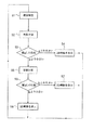
本発明は、これらの記述を基にして案出されたものであるが、次に図1に示した実施の形態における疲労度評価部で行われるべきアルゴリズムを、図4のフローチャートに基づいて説明する。まず、左右の3次元映像信号から視差pの検出が行われる(ステップS1)。次いで、検出された視差pに基づいて疲労度を評価するための関数計算が行われる(ステップS2)。この関数計算は、立体映像の視差が観察者の目に与える影響(疲労)を考慮して行われる。例えば、この目に与える影響度は、図3の輻輳(視差)−調節(視距離)の対応関係と許容範囲を示した図から求められる。この図3では、輻輳(視差)と調節(視距離)との差が大きければ大きいほど、目に与える影響度(疲労度)が大きいことを表している。この場合の影響度を表す関数f(p)の例としては、次式(1)で示すように、(視距離−視差)が大きければ大きいほど非線形で影響度が増大する関数を作成する。
影響度=α(視距離−視差)2 +β(視距離−視差)+γ ・・・・(1)
また、本件発明者の実験結果から、視差の時間的変動が大きいほど目に対する影響度が大きいことも分かっている。したがって、影響度を表す関数f(p)の例としては、次式(2)で示すような関数を作成することもできる。

【0014】
次に、上記関数計算で求められた影響度の値f(p)を、立体映像として認識できる輻輳(融像)許容限界値a(例えば、図3における黒点実線値)と比較する(ステップS3)。この輻輳許容限界値aは疲労許容限界値とみなすことができる。視差に基づく関数計算で求められた影響度の値f(p)が輻輳許容限界値aより大きい場合は、2次元映像を切り替え表示する(ステップS4)。影響度の値f(p)が輻輳許容限界値aより小さい場合は、影響度の値f(p)の時間累積計算を行う(ステップS5)。次いで、視差に基づく関数計算で求めた影響度の値f(p)の累積計算値が累積輻輳許容限界値bと比較される(ステップS6)。この累積輻輳許容限界値bは、累積疲労許容限界値とみなすことができるものであり、機器メーカが予め設定しておくか、ユーザが個別に調節して設定するか、更には実際の使用時にユーザが疲労度に応じて設定してやるようにすることもできる。累積輻輳許容限界値bを超えた場合には、2次元映像を切り替え表示する(ステップS7)。累積輻輳許容限界値bより小さい場合には、そのまま3次元(立体)映像を表示し(ステップS8)、以上の動作を繰り返し実行する。
【0015】
このアルゴリズムによれば、短時間的に融像限界を超えた3次元映像を受け取った時は、自動的に2次元映像に切り替わり、影響度の低い映像に戻ったら、表示を立体映像に戻す。そして、長時間3次元映像を観察することによって疲労が蓄積され限界値を超えたら、自動的に2次元映像に切り替わり、それ以後は2次元映像を観察することになる。
【0016】
次に、図4に示したアルゴリズムを実行する視差量検出部と疲労度評価部の構成を図5のブロック構成図に基づいて説明する。視差量検出部2は、左右の映像信号の相関計算を行って視差信号pを求める相関演算部2−1で構成されている。疲労度評価部3には、視差量検出部2から出力される視差信号pを受けて、それに対応する影響度(疲労度)の関数の値f(p)を出力する関数計算部3−1を備えている。この関数計算部3−1では実際に関数計算を行うのではなく、ROMの中にテーブルを備えていて、視差信号pの値が入力されると、それに対応する影響度(疲労度)に相当する関数の値f(p)が読み出されるようになっている。
【0017】
また、疲労度評価部3には、関数計算部3−1から出力される関数の値f(p)を入力し、前述の輻輳許容限界値aと比較する第1の比較部3−2と、同じく関数計算部3−1から出力される関数の値f(p)を入力し、その値f(p)の時間累積計算する累積計算部3−3とを備えている。前記第1の比較部3−2において、関数計算部3−1からの値f(p)が輻輳許容限界値aより大きい場合には、立体映像を一時的に2次元映像に切り換える信号を3次元映像/2次元映像切替部4へ出力すると共に、前記累積計算部3−3に対して累積計算を一時的に停止させるための停止信号を送出するように構成されている。また、更に疲労度評価部3には、前記累積計算部3−3から出力される累積値と前記累積輻輳許容限界値bとを比較する第2の比較部3−4を備えていて、累積計算部3−3からの累積値が累積輻輳許容限界値bを超えたときには、立体映像を2次元映像に切り替える信号を常に送出するように構成されている。なお、上記第2の比較部3−4において用いられる累積輻輳許容限界値bの値は、先に述べたように種々の方法で設定することが可能なので、その設定方法に応じたb値の設定手段を設けるようにする。
【0018】
次に、第2の実施の形態について説明する。図6は第2の実施の形態を示すブロック構成図で、図1に示した第1の実施の形態と同一の構成要素には同一の符号を付して示している。この実施の形態は、第1の実施の形態における3次元映像/2次元映像切替部4の代わりに視差量変換部6を設け、図5に示した第1の実施の形態と同様の構成の疲労度評価部3の視差に対応する関数値f(p)と輻輳許容限界値aとを比較する第1の比較部からの出力信号(視差抑制信号)、及び視差に対応する関数値f(p)の累積計算値と累積輻輳許容限界値bとを比較する第2の比較部からの出力信号(視差抑制信号)に基づいて、立体映像信号の視差量(立体度)を抑制視差量、すなわち例えば継続して観察しても疲労しない目標視差量(抑制立体度)に変換し、抑制立体映像信号を出力するように構成するものである。この目標視差量は、継続観察による累積した疲労が許容される値、すなわち累積疲労許容値に対応するものである。
【0019】
次に、抑制視差量の立体映像信号に変換する例を、図7に基づいて説明する。図7の(A),(B)は、立体映像再生機からの立体映像信号に基づく左眼用映像と右眼用映像とを示しており、これらの映像の視差量(XL−XR)を抑制するには、図7の(A)に示す左眼用映像全体を左側へシフトし、図7の(B)に示す右眼用映像全体を左側へシフトして、図7の(C),(D)に示すように変換する。このシフト量が視差抑制量となる。この操作により、視差量(XL′−XR′)が小さくなり、継続して観察しても疲労が生じない視差量(立体度)の立体映像とすることができる。
【0020】
上記実施の形態においては、視差量抑制の手法として、左右の映像をそれぞれ異なる方向へシフトするようにしたものを示したが、立体度の抑制手法としては奥行き圧縮で行う手法もある。すなわち、先に従来技術として例示した特開平9−116928号公報開示の2次元映像を3次元映像に変換する手法は、画像のコントラスト等から対象物の奥行き関係を推測し、その奥行きに応じて画像に歪みを生じさせることによって3次元映像を生成するものであるが、この手法を応用して、図8の(A)に示すような2次元映像において球体が三角形状体の手前にあると推測したとき、図8の(B)に示すように球体の位置が左眼用の映像と右眼用の映像で異なるように歪み〔視差(XL−XR)に相当〕を与えて立体映像を生成する。そのとき立体度を抑制する場合、図8の(C)に示すように、球体の歪み量を抑えた映像を生成する。これにより奥行きを圧縮した立体度の抑制された立体映像が得られる。このときの歪み量〔視差量(XL′−XR′)〕としては、図3の対応関係図からもわかるように、視距離(調節)の±0.5 ディオプタ内の歪み量にすることが望ましい。
【0021】
次に、第3の実施の形態について説明する。先に従来例として例示した特許第2594235号公報開示の2次元映像を3次元映像に変換する手法は、2次元映像の動きの大きさにより視差量(遅延量)を設定して、3次元映像を生成するものであるが、この手法において設定する視差量に基づいて、疲労度評価部において、2次元映像/3次元映像切り替え信号を形成するようにするものである。
【0022】
図9は第3の実施の形態を示すブロック構成図であり、21は2次元映像再生機、22は2次元映像再生機21からの2次元映像信号における動きの大きさに基づいて、視差量を決定する視差量決定部、23は図1及び図6に示した第1及び第2の実施の形態における疲労度評価部と同一構成の疲労度評価部で、視差量決定部22からの視差量を受けて2次元映像/3次元映像切り替え信号を送出するものである。24は視差量決定部22で設定された視差量を受けて2次元映像を3次元映像に変換する3次元映像生成部、25は3次元映像生成部24からの3次元映像又は2次元映像を表示する映像表示部である。
【0023】
上記図1及び図9に示した第1及び第3の実施の形態においては、疲労度評価部からの切り替え信号により、3次元映像から2次元映像へ不連続に瞬間的に切り替えるようにしている。しかし、このように瞬間的に3次元映像を2次元映像に切り替えると、視差の時間的変動量が大きいために融像できなくなる。そこで、滑らかに立体度を変えながら2次元映像に切り替える、つまり視差量を連続的に変化させるようにした図1及び図9に示した実施の形態の変形例を、図10に基づいて説明する。この変形例は、図10の(A)に示す3次元映像の左右の映像の視差(XL−XR)を、図10の(B),(C)に示すように徐々に小さくし、最終的に図10の(D)に示すようにXL=XRとして、2次元映像ににする。これにより、不快感を伴わない3次元/2次元映像の切り替えを行うことができる。
【0024】
次に、第4の実施の形態について説明する。この実施の形態は、3次元映像の視差量ではなく、画像の動きベクトルを検出し、その動きベクトルに基づいて3次元映像を2次元映像に切り替えるようにするものである。一般に、動きの激しい映像は観察者に与える影響は大きいと言われている。本実施の形態は、この現象を除去するものである。図11は第4の実施の形態を示すブロック構成図であり、31は3次元映像再生機、32は3次元映像再生機31から出力される3次元映像信号の動きベクトルを検出するための画像の動き検出部、33は画像の動き検出部32で検出された動きベクトルに基づいて疲労度を評価する疲労度評価部、34は疲労度の評価に基づいて出力される切り替え信号により、3次元映像信号と2次元映像信号とを切り替え出力する3次元映像/2次元映像切替部、35は該映像切替部34より出力される3次元映像信号又は2次元映像信号を表示する映像表示部である。
【0025】
次に、画像の動き検出部32における動きベクトルの検出例を、図12の(A)〜(C)に基づいて説明する。この検出例では、図12の(A),(B)に示すように背景が左側に移動しており、したがって図12の(C)に示すような動きベクトルが検出され、例えば、その値の平均値が疲労度評価部33へ入力されるようになっている。
【0026】
次に、この実施の形態における疲労度評価部33で行われるアルゴリズムを、図13のフローチャートに基づいて説明する。まず立体映像信号から動きベクトルmの検出が行われる(ステップS11)。次いで、検出された動きベクトルmに基づいて疲労度を評価するための関数計算が行われる(ステップS12)。この関数計算は、立体映像における画像の動きが観察者の目に与える影響(疲労)を考慮して行われる。例えば、動きベクトルの大きさや動きに基づいて関数の値f(m)が求められ、例えば、f(m)=α・m2 +β・m+γのように動きベクトルmに対して非線形で増大する関数を定める。次に、上記関数計算で求められた値f(m)を、許容限界値aと比較する(ステップS13)。動きベクトルに基づく関数計算で求められた値f(m)が許容限界値aより大きい場合、2次元映像を切り替え表示する(ステップS14)。関数の値f(m)が許容限界値aより小さい場合は、関数の値f(m)の時間累積計算を行う(ステップS15)。次いで、動きベクトルに基づく関数計算で求められた値f(m)の累積計算値を累積許容限界値bと比較する(ステップS16)。関数計算値f(m)の累積計算値が累積許容限界値bを超えた場合には、2次元映像が切り替え表示される(ステップS17)。累積許容限界値bより小さい場合には、そのまま3次元(立体)映像を表示し(ステップS18)、以上の動作を繰り返し実行する。
【0027】
次に、図13に示したアルゴリズムを実行する画像の動き検出部と疲労度評価部の構成を図14のブロック構成図に基づいて説明する。画像の動き検出部32は、立体映像信号から動きベクトルmを算出する動き量計算部32−1で構成されている。疲労度評価部33には、画像の動き検出部32から出力される動きベクトルmを受けて、それに対応する関数の値f(m)を出力する関数計算部33−1を備えている。この関数計算部33−1では、第1の実施の形態と同様に実際に関数計算を行うのではなく、ROMの中にテーブルを備えていて、動きベクトルmの値が入力されると、それに対応する影響度(疲労度)に相当する関数の値f(m)が読み出されるようになっている。
【0028】
また、疲労度評価部33には、関数計算部33−1から出力される関数の値f(m)を入力し、前述の許容限界値aと比較する第1の比較部33−2と、同じく関数計算部33−1から出力される関数の値f(m)を入力し、その値f(m)の時間累積計算する累積計算部33−3とを備えている。前記第1の比較部33−2において、関数計算部33−1からの値f(m)が許容限界値aより大きい場合には、立体映像を一時的に2次元映像に切り替える信号を立体映像/2次元映像切り替え部34へ出力すると共に、前記累積計算部33−3に対して累積計算を一時的に停止させるための停止信号を送出するように構成されている。また更に疲労度評価部33には、前記累積計算部33−3から出力される累積値と前記累積輻輳許容限界値bとを比較する第2の比較部33−4を備えていて、累積計算部33−3からの累積値が累積輻輳許容限界値bを超えたときには、立体映像を常に2次元映像に切り替える信号を送出するように構成されている。
【0029】
次に、第5の実施の形態について説明する。この実施の形態は、第3の実施の形態と同様に2次元映像の動きの大きさにより視差量(遅延量)を設定して、3次元映像を生成する際に検出する2次元映像の動きの大きさを用いて、疲労度評価部において、3次元/2次元映像切り替え信号を形成するように構成するものである。
【0030】
図15は第5の実施の形態を示すブロック構成図であり、41は2次元映像再生機、42は2次元映像再生機41からの2次元映像信号に基づいて動きベクトルを検出する動き量検出部、43は図11に示した第4の実施の形態における疲労度評価部33と同一構成の、動き量検出部42からの動きベクトルを受けて3次元/2次元映像切り替え信号を送出する疲労度評価部である。44は動き量検出部42で検出された動きベクトルを受けて2次元映像を3次元映像に変換する3次元映像生成部、45は3次元映像生成部44からの3次元映像又は2次元映像を表示する映像表示部である。
【0031】
また、上記第4及び第5の実施の形態においても、疲労度評価部からの出力信号により、3次元映像を2次元映像に切り替える代わりに、3次元映像の立体度を抑制するように構成することもできる。また、図7,図8及び図10に示したように、滑らかに視差量を変化させていくように構成することもできる。
【0032】
【発明の効果】
以上実施の形態に基づいて説明したように、請求項1及び2に係る発明によれば、入力された映像信号からの映像の視差量に基づいて観察者に与える影響度を評価し、その影響度評価量に基づいて得られる影響度の時間的な累積量によって立体映像の立体度を抑制制御、あるいは立体映像を2次元映像へ切り替え制御するように構成しているので、観察者の生体的な計測を行うことなく、観察者に疲労等の影響を与えないように立体映像を適切に制御することが可能な映像システムを実現することができる。
【図面の簡単な説明】
【図1】本発明に係る映像システムの第1の実施の形態を示す概略ブロック構成図である。
【図2】3次元映像における視差量を説明するための説明図である。
【図3】視差量と疲労度の関係を説明するための輻輳と調節の対応関係と許容範囲を示す図である。
【図4】図1に示した第1の実施の形態における疲労度評価部で行われるアルゴリズムを説明するためのフローチャートである。
【図5】図1に示した第1の実施の形態における疲労度評価部の構成を示すブロック図である。
【図6】本発明の第2の実施の形態を示すブロック構成図である。
【図7】立体映像の立体度抑制の例を示す説明図である。
【図8】立体映像の立体度抑制の他の例を示す説明図である。
【図9】本発明の第3の実施の形態を示すブロック構成図である。
【図10】立体映像において視差量を連続的に変化させる態様を示す図である。
【図11】本発明の第4の実施の形態を示すブロック構成図である。
【図12】映像における動きベクトルの検出例を示す説明図である。
【図13】図11に示した第4の実施の形態における疲労度評価部で行われるアルゴリズムを説明するためのフローチャートである。
【図14】図11に示した第4の実施の形態における疲労度評価部の構成を示すブロック図である。
【図15】本発明の第5の実施の形態を示すブロック構成図である。
【符号の説明】
1 3次元映像再生機
2 視差量検出部
2−1 相関計算部
3 疲労度評価部
3−1 関数計算部
3−2 第1の比較部
3−3 累積計算部
3−4 第2の比較部
4 3次元映像/2次元映像切り替え部
5 映像表示部
6 視差量変換部
11a 左眼
11b 右眼
12 レンズ
13a 左眼用LCD映像表示部
13b 右眼用LCD映像表示部
14 融像位置
15 虚像位置
21 2次元映像再生機
22 視差量決定部
23 疲労度評価部
24 3次元映像生成部
25 映像表示部
31 3次元映像再生機
32 画像の動き検出部
32−1 動き量計算部
33 疲労度評価部
33−1 関数計算部
33−2 第1の比較部
33−3 累積計算部
33−4 第2の比較部
34 3次元映像/2次元映像切り替え部
35 映像表示部
41 2次元映像再生機
42 動き量検出部
43 疲労度評価部
44 3次元映像生成部
45 映像表示部[0001]
BACKGROUND OF THE INVENTION
The present invention relates to a video system, and more particularly to a video system in which the degree of influence on an observer is evaluated based on a video signal to control the stereoscopic degree.
[0002]
[Prior art]
Conventionally, various proposals have been made regarding video systems. For example, Japanese Patent No. 2594235 discloses a main video as a reference from a 2D video signal as a technique for converting a 2D video into a 3D video. Generating a signal and a sub-video signal delayed with respect to the main video signal, detecting a horizontal motion magnitude and direction of the video from the two-dimensional video signal, and determining the sub-video according to the motion magnitude. A delay amount for generating a signal is determined, and video switching means for inputting the main and sub video signals is controlled according to the direction of the movement, and either the main or sub video signal is selected as a left eye video signal or a right eye video signal. There has been disclosed a method for converting a two-dimensional image determined to be output into a three-dimensional image.
[0003]
Japanese Patent Laid-Open No. 9-116928 generates a first phase-shifted video in which the horizontal phase gradually delays in the vertical direction for each field based on a two-dimensional input video, and Based on this, a second phase-shifted video in which the horizontal phase gradually advances in the vertical direction for each field is generated, and one of the first phase-shifted video and the second phase-shifted video is used as the left-eye video. A method for converting a two-dimensional image into a three-dimensional image using the other as the right-eye image has been disclosed.
[0004]
By the way, it is generally said that when a stereoscopic image is observed, the eyes are more easily fatigued than when a normal two-dimensional image is observed. As a proposal in consideration of this point, Japanese Patent Application Laid-Open No. 9-23451 provides stereoscopic image viewing glasses with a sensor for detecting the skin temperature of the forehead and a sensor for detecting the skin temperature of the nose. The excitement level is output from the exciter level data converter, and a sensor for detecting blinking is provided in the glasses for viewing stereoscopic images, and the fatigue level is output based on the detection output. The stereoscopic enhancement level is output from the stereoscopic enhancement level control circuit, and the delay amount of the field memory of the stereoscopic television receiver that performs two-dimensional and three-dimensional conversion is controlled by the stereoscopic enhancement level, and a desired stereoscopic level is selected according to the sensitivity of the user. There has been disclosed a control device that can control the state.
[0005]
[Problems to be solved by the invention]
However, as in the method disclosed in the above publication, when the stereoscopic degree of a stereoscopic image is controlled based on the degree of excitement and fatigue of the user, there are large individual differences in the user's biological measurement values, and all observations It is difficult for a person to determine an appropriate limit value of fatigue level from biological measurement values, and it is also troublesome to obtain measurement values individually from each observer.
[0006]
The present invention has been made in order to solve the above-described problems in the conventional stereoscopic image control apparatus for stereoscopic images. By estimating the degree of influence that would be given to an observer based on an input image signal, It is an object of the present invention to provide a video system in which the stereoscopic degree can be appropriately controlled.
[0007]
[Means for Solving the Problems]
In order to solve the above-mentioned problem, the invention according to claim 1 is inputted in a video system. For stereoscopic viewing Video signal Caused by the difference between the parallax and viewing distance Observer Affect the observer as fatigue of the eyes The degree of influence A parallax amount of the video is detected from the input video signal, and based on the parallax amount The degree of influence evaluation means to be evaluated, and the stereoscopic degree of the stereoscopic video presented to the observer based on the degree of influence evaluation obtained by the influence degree evaluation means Parallax is The Therefore, even if it is continuously observed, it can be given to the observer without a feeling of fatigue. Suppression control Converted to a video signal And a three-dimensionality control means. 2 The invention according to the present invention is inputted in a video system. For stereoscopic viewing Video signal Caused by the difference between the parallax and viewing distance Observer Affect the observer as fatigue of the eyes The degree of influence A parallax amount of the video is detected from the input video signal, and based on the parallax amount Based on the impact assessment means to be evaluated and the impact assessment amount obtained by the impact assessment means If the cumulative amount of the degree of influence obtained over time is larger than the limit value of the cumulative influence allowable limit value, it is presented to the observer. And a means for switching and controlling a stereoscopic video to a two-dimensional video.
[0008]
As described above, claims 1 and 2 The invention according to the present invention is based on an input video signal. Based on the amount of parallax of video Evaluate the impact on the observer and based on the impact assessment Depending on the cumulative amount of impact obtained over time Since the stereoscopic degree of the stereoscopic video is controlled to be suppressed, or the stereoscopic video is switched to the two-dimensional video, the observer's biological measurement is not performed, and the observer is not affected by fatigue or the like. A video system capable of appropriately controlling stereoscopic video can be realized.
[0009]
DETAILED DESCRIPTION OF THE INVENTION
Next, embodiments will be described. FIG. 1 is a schematic block diagram showing a first embodiment of a video system according to the present invention. In FIG. 1, 1 is a 3D video player that transmits a 3D video signal, 2 is a parallax amount detection unit for detecting the parallax amount of the 3D video signal output from the 3D video player 1, A fatigue level evaluation unit that evaluates the fatigue level based on the parallax amount detected by the parallax
[0010]
Next, the amount of parallax in the 3D video signal will be described based on (A) to (C) of FIG. FIG. 2A is a diagram showing an observation mode in the case of a three-dimensional (stereoscopic) image in which a sphere appears to pop out. 11a and 11b are the left eye and the right eye, respectively, and 12 is immediately before the left eye and the right eye. The arranged
[0011]
In FIG. 2A,
[0012]
Next, the relationship between the amount of parallax and the degree of fatigue will be described. “Physiological Engineering” (published by New Technology Communications, Inc., December 1985, pages 103-105) includes the following relationship with the diagram showing the correspondence between congestion and regulation shown in FIG. Is described. The convergence on the horizontal axis in FIG. 3 corresponds to the convergence distance, and is represented by the convergence angle (MW) and its reciprocal distance. On the other hand, the adjustment on the vertical axis corresponds to the viewing distance and is represented by diopter D. In FIG. 3, the solid line at the center of 45 ° is a part where the convergence-adjustment corresponds completely, and the area in the vicinity thereof shows an allowable range depending on the depth of focus, but the visual acuity (ε: 5μ), and the range is slightly different by adopting the blur detection capability (δ: 15μ). The outer curve shows the fusion limit of both eyes. The solid black line is the maximum fusion limit, the dotted line is the range in which the fusion is established again from the double image state, and the broken line is when the image presentation time is 0.5 seconds. Indicates the fusion limit. In addition, it is described that a moving image has a considerable fatigue feeling in long-time observation unless it is a three-dimensional reproduction within a broken line range.
[0013]
The present invention has been devised based on these descriptions. Next, an algorithm to be performed by the fatigue evaluation unit in the embodiment shown in FIG. 1 will be described based on the flowchart of FIG. To do. First, the parallax p is detected from the left and right 3D video signals (step S1). Next, a function calculation for evaluating the degree of fatigue is performed based on the detected parallax p (step S2). This function calculation is performed in consideration of the influence (fatigue) that the parallax of the stereoscopic video has on the eyes of the observer. For example, the degree of influence on the eyes can be obtained from the diagram showing the correspondence between the convergence (parallax) -adjustment (viewing distance) and the allowable range in FIG. FIG. 3 shows that the greater the difference between convergence (parallax) and adjustment (viewing distance), the greater the degree of influence (fatigue) on the eyes. As an example of the function f (p) representing the degree of influence in this case, as shown by the following equation (1), a function is created in which the degree of influence increases nonlinearly as (viewing distance-parallax) increases.
Influence = α (viewing distance−parallax) 2 + Β (viewing distance−parallax) + γ (1)
Further, it has been found from the experiment result of the present inventor that the degree of influence on the eyes increases as the temporal variation in parallax increases. Therefore, as an example of the function f (p) representing the degree of influence, a function represented by the following equation (2) can be created.
[0014]
Next, the influence value f (p) obtained by the above function calculation is compared with a convergence (fusion) allowable limit value a that can be recognized as a stereoscopic image (for example, a solid line value in FIG. 3) (step S3). ). This congestion tolerance limit value a can be regarded as a fatigue tolerance limit value. When the influence value f (p) obtained by the function calculation based on the parallax is larger than the allowable congestion limit value a, the two-dimensional video is switched and displayed (step S4). When the influence value f (p) is smaller than the congestion tolerance limit value a, the time accumulation calculation of the influence value f (p) is performed (step S5). Next, the cumulative calculation value of the influence value f (p) obtained by the function calculation based on the parallax is compared with the cumulative congestion allowable limit value b (step S6). This cumulative congestion allowable limit value b can be regarded as a cumulative fatigue allowable limit value, and is set in advance by the device manufacturer, individually adjusted by the user, or even in actual use. The user can also set according to the degree of fatigue. When the accumulated congestion allowable limit value b is exceeded, the two-dimensional video is switched and displayed (step S7). If it is smaller than the accumulated congestion allowable limit value b, the three-dimensional (stereoscopic) video is displayed as it is (step S8), and the above operations are repeated.
[0015]
According to this algorithm, when a 3D image exceeding the fusion limit is received in a short time, the image is automatically switched to a 2D image, and when the image returns to a low-impact image, the display is returned to a stereoscopic image. If fatigue is accumulated and the limit value is exceeded by observing the 3D image for a long time, the 2D image is automatically switched, and thereafter, the 2D image is observed.
[0016]
Next, configurations of the parallax amount detection unit and the fatigue evaluation unit that execute the algorithm illustrated in FIG. 4 will be described based on the block configuration diagram of FIG. 5. The parallax
[0017]
Further, the fatigue
[0018]
Next, a second embodiment will be described. FIG. 6 is a block diagram showing the second embodiment, and the same components as those in the first embodiment shown in FIG. In this embodiment, a parallax
[0019]
Next, an example of converting into a stereoscopic video signal with a suppressed parallax amount will be described with reference to FIG. 7A and 7B show a left-eye video and a right-eye video based on the stereoscopic video signal from the stereoscopic video player, and the parallax amount (XL-XR) of these videos is shown. To suppress, the entire left-eye image shown in FIG. 7A is shifted to the left, the entire right-eye image shown in FIG. 7B is shifted to the left, and FIG. , (D). This shift amount becomes the parallax suppression amount. By this operation, the parallax amount (XL′−XR ′) is reduced, and a stereoscopic image having a parallax amount (stericity) that does not cause fatigue even when continuously observed can be obtained.
[0020]
In the above embodiment, the parallax amount suppression method has been described in which the left and right videos are shifted in different directions. However, as a stereoscopic degree suppression method, there is also a method of performing depth compression. That is, the method of converting the 2D video disclosed in Japanese Patent Laid-Open No. 9-116928, which has been exemplified as the prior art, into the 3D video, infers the depth relationship of the object from the contrast of the image and the like, and according to the depth A three-dimensional image is generated by generating distortion in an image, but if this technique is applied and a sphere is in front of a triangular body in a two-dimensional image as shown in FIG. When inferred, as shown in FIG. 8B, the stereoscopic image is given with distortion (corresponding to parallax (XL-XR)) so that the position of the sphere is different between the image for the left eye and the image for the right eye. Generate. At that time, when the degree of stereo is suppressed, an image in which the amount of distortion of the sphere is suppressed is generated as shown in FIG. As a result, a stereoscopic image in which the depth is compressed and the stereoscopic degree is suppressed is obtained. The distortion amount [parallax amount (XL′−XR ′)] at this time is preferably set to a distortion amount within ± 0.5 diopters of the viewing distance (adjustment), as can be seen from the correspondence diagram of FIG.
[0021]
Next, a third embodiment will be described. The method of converting the 2D video disclosed in Japanese Patent No. 2594235, which was previously exemplified as the conventional example, into the 3D video, sets the amount of parallax (delay amount) according to the magnitude of the motion of the 2D video, and the 3D video. However, based on the parallax amount set in this method, the fatigue evaluation unit forms a 2D video / 3D video switching signal.
[0022]
FIG. 9 is a block diagram showing the third embodiment, in which 21 is a 2D video player, 22 is a parallax amount based on the magnitude of motion in a 2D video signal from the
[0023]
In the first and third embodiments shown in FIGS. 1 and 9, the switching signal from the fatigue evaluation unit instantaneously switches from 3D video to 2D video in a discontinuous manner. . However, if the 3D video is instantaneously switched to the 2D video in this way, the temporal variation of the parallax is large and fusion cannot be performed. Accordingly, a modification of the embodiment shown in FIGS. 1 and 9 in which switching to a two-dimensional image is performed while smoothly changing the stereoscopic degree, that is, the parallax amount is continuously changed will be described based on FIG. . In this modification, the parallax (XL-XR) of the left and right images of the three-dimensional image shown in FIG. 10A is gradually reduced as shown in FIGS. As shown in FIG. 10D, XL = XR is set to form a two-dimensional image. As a result, it is possible to perform switching between 3D / 2D video without discomfort.
[0024]
Next, a fourth embodiment will be described. In this embodiment, the motion vector of an image is detected instead of the amount of parallax of the 3D video, and the 3D video is switched to the 2D video based on the motion vector. In general, it is said that an image with intense movement has a great influence on an observer. The present embodiment eliminates this phenomenon. FIG. 11 is a block diagram showing the fourth embodiment, in which 31 is a 3D video player, and 32 is an image for detecting a motion vector of a 3D video signal output from the
[0025]
Next, the
[0026]
Next, an algorithm performed by the
[0027]
Next, the configuration of the image motion detection unit and the fatigue evaluation unit that execute the algorithm shown in FIG. 13 will be described based on the block configuration diagram of FIG. The image
[0028]
Further, the fatigue
[0029]
Next, a fifth embodiment will be described. As in the third embodiment, this embodiment sets the parallax amount (delay amount) according to the magnitude of the motion of the 2D video, and detects the motion of the 2D video detected when generating the 3D video. Is used to form a 3D / 2D video switching signal in the fatigue evaluation unit.
[0030]
FIG. 15 is a block diagram showing the fifth embodiment. 41 is a 2D video player, 42 is a motion amount detection that detects a motion vector based on a 2D video signal from the
[0031]
The fourth and fifth embodiments are also configured to suppress the three-dimensionality of the three-dimensional video instead of switching the three-dimensional video to the two-dimensional video by the output signal from the fatigue evaluation unit. You can also. Further, as shown in FIGS. 7, 8, and 10, the parallax amount can be changed smoothly.
[0032]
【The invention's effect】
As described above based on the embodiments, claims 1 and 2 According to the invention concerning the above, from the input video signal Based on the amount of parallax of video Evaluate the impact on the observer and based on the impact assessment Depending on the cumulative amount of impact obtained over time Since it is configured to control and control the stereoscopic degree of the stereoscopic video or to switch the stereoscopic video to the two-dimensional video, it does not affect the observer, such as fatigue, without performing biological measurement of the observer. Thus, it is possible to realize a video system capable of appropriately controlling a stereoscopic video.
[Brief description of the drawings]
FIG. 1 is a schematic block diagram showing a first embodiment of a video system according to the present invention.
FIG. 2 is an explanatory diagram for explaining a parallax amount in a three-dimensional image.
FIG. 3 is a diagram illustrating a correspondence relationship between congestion and adjustment and an allowable range for explaining a relationship between an amount of parallax and a fatigue level.
FIG. 4 is a flowchart for explaining an algorithm performed by a fatigue evaluation unit in the first embodiment shown in FIG. 1;
FIG. 5 is a block diagram showing a configuration of a fatigue evaluation unit in the first embodiment shown in FIG. 1;
FIG. 6 is a block diagram showing a second embodiment of the present invention.
FIG. 7 is an explanatory diagram illustrating an example of stereoscopic degree suppression of a stereoscopic video.
FIG. 8 is an explanatory diagram illustrating another example of stereoscopic degree suppression of stereoscopic video.
FIG. 9 is a block diagram showing a third embodiment of the present invention.
FIG. 10 is a diagram illustrating an aspect in which a parallax amount is continuously changed in a stereoscopic video.
FIG. 11 is a block diagram showing a fourth embodiment of the present invention.
FIG. 12 is an explanatory diagram showing an example of motion vector detection in a video.
FIG. 13 is a flowchart for explaining an algorithm performed in a fatigue evaluation unit in the fourth embodiment shown in FIG. 11;
FIG. 14 is a block diagram showing a configuration of a fatigue evaluation unit in the fourth embodiment shown in FIG.
FIG. 15 is a block diagram showing a fifth embodiment of the present invention.
[Explanation of symbols]
1 3D video player
2 Parallax amount detector
2-1 Correlation calculator
3 Fatigue evaluation section
3-1 Function calculator
3-2 First comparison unit
3-3 Cumulative calculation part
3-4 Second comparison unit
4 3D video / 2D video switching unit
5 Video display section
6 Parallax conversion unit
11a left eye
11b Right eye
12 Lens
13a LCD image display for left eye
13b LCD image display for right eye
14 Fusion position
15 Virtual image position
21 2D video player
22 Parallax amount determination unit
23 Fatigue evaluation section
24 3D image generator
25 Video display
31 3D video player
32 Image motion detector
32-1 Motion amount calculator
33 Fatigue evaluation section
33-1 Function calculator
33-2 First comparison section
33-3 Cumulative calculation part
33-4 Second comparison section
34 3D / 2D switching part
35 Video display
41 2D video player
42 Motion detection unit
43 Fatigue evaluation section
44 3D image generator
45 Video display
Claims (3)
該影響度評価手段で得られた影響度評価量に基づいて観察者へ提示する立体映像の立体度である視差を、継続して観察しても疲労感なく観察者へ与えることが可能であるように、前記影響度の時間的な累積量の限界値である累積影響許容限界値以下に抑制制御した映像信号に変換する立体度制御手段と、
を備えていることを特徴とする映像システム。The parallax of the video from the input video signal is determined by the difference between the parallax and the viewing distance of the video signal for performing stereoscopic viewing and affecting the observer as fatigue of the observer's eyes An impact evaluation means for detecting the amount and evaluating based on the amount of parallax;
Even if the parallax, which is the stereoscopic degree of the stereoscopic video presented to the observer based on the influence degree evaluation amount obtained by the influence degree evaluating means, is continuously observed, it can be given to the observer without feeling tired. As described above, a stereoscopic degree control means for converting into a video signal that is controlled to be less than or equal to a cumulative influence allowable limit value that is a limit value of a temporal accumulation amount of the influence degree,
A video system characterized by comprising:
該影響度評価手段で得られた影響度評価量に基づいて得られる前記影響度の時間的な累積量がその限界値である累積影響許容限界値より大きい場合には観察者へ提示する立体映像を2次元映像に切り替え制御する手段と、
を備えていることを特徴とする映像システム。The parallax of the video from the input video signal is determined by the difference between the parallax and the viewing distance of the video signal for performing stereoscopic viewing and affecting the observer as fatigue of the observer's eyes An impact evaluation means for detecting the amount and evaluating based on the amount of parallax;
A stereoscopic image to be presented to an observer when the temporal cumulative amount of the degree of influence obtained based on the degree of influence evaluation obtained by the degree of influence evaluation means is larger than the cumulative influence allowable limit value that is the limit value. Means for switching to 2D video,
A video system characterized by comprising:
Priority Applications (5)
| Application Number | Priority Date | Filing Date | Title |
|---|---|---|---|
| JP17053198A JP4149037B2 (en) | 1998-06-04 | 1998-06-04 | Video system |
| DE69943034T DE69943034D1 (en) | 1998-06-04 | 1999-05-19 | Stereoscopic imaging system |
| EP99303904A EP0963122B1 (en) | 1998-06-04 | 1999-05-19 | Stereoscopic imaging system |
| US09/323,694 US6614927B1 (en) | 1998-06-04 | 1999-06-02 | Visual image system |
| US10/611,963 US6996267B2 (en) | 1998-06-04 | 2003-07-03 | Visual image system |
Applications Claiming Priority (1)
| Application Number | Priority Date | Filing Date | Title |
|---|---|---|---|
| JP17053198A JP4149037B2 (en) | 1998-06-04 | 1998-06-04 | Video system |
Publications (2)
| Publication Number | Publication Date |
|---|---|
| JPH11355808A JPH11355808A (en) | 1999-12-24 |
| JP4149037B2 true JP4149037B2 (en) | 2008-09-10 |
Family
ID=15906660
Family Applications (1)
| Application Number | Title | Priority Date | Filing Date |
|---|---|---|---|
| JP17053198A Expired - Fee Related JP4149037B2 (en) | 1998-06-04 | 1998-06-04 | Video system |
Country Status (4)
| Country | Link |
|---|---|
| US (2) | US6614927B1 (en) |
| EP (1) | EP0963122B1 (en) |
| JP (1) | JP4149037B2 (en) |
| DE (1) | DE69943034D1 (en) |
Cited By (3)
| Publication number | Priority date | Publication date | Assignee | Title |
|---|---|---|---|---|
| CN103780894A (en) * | 2012-10-18 | 2014-05-07 | 财团法人工业技术研究院 | Three-dimensional film playing method with visual fatigue estimation and control system |
| US9300942B2 (en) | 2012-10-18 | 2016-03-29 | Industrial Technology Research Institute | Method and control system for three-dimensional video playback using visual fatigue estimation |
| US10108853B2 (en) | 2013-08-13 | 2018-10-23 | Samsung Electronics Co., Ltd. | Apparatus and method to estimate a degree of user fatigue to video content |
Families Citing this family (133)
| Publication number | Priority date | Publication date | Assignee | Title |
|---|---|---|---|---|
| JP2003018619A (en) * | 2001-07-03 | 2003-01-17 | Olympus Optical Co Ltd | Three-dimensional image evaluation apparatus and display using the same |
| GB0129992D0 (en) * | 2001-12-14 | 2002-02-06 | Ocuity Ltd | Control of optical switching apparatus |
| JP3673217B2 (en) * | 2001-12-20 | 2005-07-20 | オリンパス株式会社 | Video display device |
| WO2004021285A1 (en) * | 2002-08-27 | 2004-03-11 | Sharp Kabushiki Kaisha | Content reproduction device capable of reproducing a content in optimal reproduction mode |
| EP1403759A3 (en) * | 2002-09-17 | 2007-04-04 | Sharp Kabushiki Kaisha | Electronic equipment with two and three dimensional display functions |
| JP2004165709A (en) * | 2002-09-27 | 2004-06-10 | Sharp Corp | Stereoscopic image display apparatus, stereoscopic image recording method, and stereoscopic image transmission method |
| KR100804572B1 (en) | 2002-09-27 | 2008-02-20 | 샤프 가부시키가이샤 | 3-d image display unit, 3-d image recording device, 3-d image encoding device, 3-d image decoding device, 3-d image recording method and 3-d image transmitting method |
| JP2004165710A (en) * | 2002-09-27 | 2004-06-10 | Sharp Corp | Stereoscopic image display apparatus, stereoscopic image recording method, and stereoscopic image transmission method |
| JP4145122B2 (en) * | 2002-09-27 | 2008-09-03 | シャープ株式会社 | Stereoscopic image display device |
| CN1703915A (en) * | 2002-09-27 | 2005-11-30 | 夏普株式会社 | 3-D image display unit, 3-D image recording device and 3-D image recording method |
| JP4713054B2 (en) * | 2002-09-27 | 2011-06-29 | シャープ株式会社 | Stereo image display device, stereo image encoding device, stereo image decoding device, stereo image recording method, and stereo image transmission method |
| CN101873488B (en) | 2002-11-01 | 2012-05-30 | 松下电器产业株式会社 | Motion picture encoding method and device, and motion picture decoding method and device |
| JP2004246725A (en) * | 2003-02-14 | 2004-09-02 | Sharp Corp | Display device, display control device, display control program, and computer-readable recording medium recording the same |
| JP4490074B2 (en) | 2003-04-17 | 2010-06-23 | ソニー株式会社 | Stereoscopic image processing apparatus, stereoscopic image display apparatus, stereoscopic image providing method, and stereoscopic image processing system |
| US20040222987A1 (en) * | 2003-05-08 | 2004-11-11 | Chang Nelson Liang An | Multiframe image processing |
| WO2004107765A1 (en) * | 2003-05-28 | 2004-12-09 | Sanyo Electric Co., Ltd. | 3-dimensional video display device, text data processing device, program, and storage medium |
| JP2004357156A (en) * | 2003-05-30 | 2004-12-16 | Sharp Corp | Video reception apparatus and video playback apparatus |
| US7411611B2 (en) * | 2003-08-25 | 2008-08-12 | Barco N. V. | Device and method for performing multiple view imaging by means of a plurality of video processing devices |
| JP4841250B2 (en) * | 2003-12-19 | 2011-12-21 | ティディヴィジョン コーポレイション エス.エー. デ シー.ヴィ. | 3D video game system |
| JP4665430B2 (en) * | 2004-04-26 | 2011-04-06 | 富士ゼロックス株式会社 | Image output control device, image output control method, image output control program, and printer device |
| WO2006016315A1 (en) | 2004-08-10 | 2006-02-16 | Koninklijke Philips Electronics N.V. | Detection of view mode |
| KR100861476B1 (en) * | 2004-08-18 | 2008-10-02 | 샤프 가부시키가이샤 | Image data display apparatus |
| WO2006019039A1 (en) * | 2004-08-18 | 2006-02-23 | Sharp Kabushiki Kaisha | Image data display |
| JP4602737B2 (en) * | 2004-10-25 | 2010-12-22 | シャープ株式会社 | Video display device |
| JP4246691B2 (en) * | 2004-11-30 | 2009-04-02 | 本田技研工業株式会社 | Image information processing system, image information processing method, image information processing program, and automobile |
| US20060139448A1 (en) * | 2004-12-29 | 2006-06-29 | Samsung Electronics Co., Ltd. | 3D displays with flexible switching capability of 2D/3D viewing modes |
| JP4046121B2 (en) * | 2005-03-24 | 2008-02-13 | セイコーエプソン株式会社 | Stereoscopic image display apparatus and method |
| JP4555722B2 (en) * | 2005-04-13 | 2010-10-06 | 株式会社 日立ディスプレイズ | 3D image generator |
| KR100913173B1 (en) | 2005-07-05 | 2009-08-19 | 삼성모바일디스플레이주식회사 | 3 dimension graphic processor and autostereoscopic display device using the same |
| KR100932977B1 (en) | 2005-07-05 | 2009-12-21 | 삼성모바일디스플레이주식회사 | Stereoscopic video display |
| US8885017B2 (en) * | 2005-07-14 | 2014-11-11 | 3Ality Digital Systems, Llc | Real-time process and technology using image processing to maintain and ensure viewer comfort during capture, live transmission, and post-production of stereoscopic 3D imagery |
| EP1750460A1 (en) * | 2005-08-05 | 2007-02-07 | Samsung SDI Co., Ltd. | 3D graphics processor and autostereoscopic display device using the same |
| KR100739730B1 (en) * | 2005-09-03 | 2007-07-13 | 삼성전자주식회사 | Apparatus and method for processing 3D dimensional picture |
| KR100739764B1 (en) | 2005-11-28 | 2007-07-13 | 삼성전자주식회사 | Apparatus and method for processing 3 dimensional video signal |
| CN101341760B (en) * | 2005-12-19 | 2012-12-12 | 皇家飞利浦电子股份有限公司 | 3D image display method and apparatus |
| KR101102004B1 (en) * | 2005-12-30 | 2012-01-04 | 삼성전자주식회사 | A method and system for quantitating fatigue resulting from a three dimensional display |
| US8274448B1 (en) | 2006-03-29 | 2012-09-25 | Nvidia Corporation | Stereoscopic display system, method and computer program product |
| KR100893616B1 (en) | 2006-04-17 | 2009-04-20 | 삼성모바일디스플레이주식회사 | Electronic imaging device, 2d/3d image display device and the driving method thereof |
| TWI331872B (en) * | 2006-12-29 | 2010-10-11 | Quanta Comp Inc | Method for displaying stereoscopic image |
| KR101313740B1 (en) * | 2007-10-08 | 2013-10-15 | 주식회사 스테레오피아 | OSMU( One Source Multi Use)-type Stereoscopic Camera and Method of Making Stereoscopic Video Content thereof |
| WO2009075495A1 (en) * | 2007-12-10 | 2009-06-18 | Samsung Electronics Co., Ltd. | System and method for generating and reproducing image file including 2d image and 3d stereoscopic image |
| BRPI0820739B1 (en) * | 2007-12-14 | 2020-10-20 | Koninklijke Philips N.V. | method of reproducing video information, reproduction device for reproducing video information, signal, and, recording carrier |
| EP2274920B1 (en) | 2008-05-12 | 2019-01-16 | InterDigital Madison Patent Holdings | System and method for measuring potential eyestrain of stereoscopic motion pictures |
| KR100991804B1 (en) * | 2008-06-10 | 2010-11-04 | 유한회사 마스터이미지쓰리디아시아 | Stereoscopic Image Generation Chip For Mobile Equipment, and Method For Generating Stereoscopic Image Using The Same |
| KR20100002032A (en) * | 2008-06-24 | 2010-01-06 | 삼성전자주식회사 | Image generating method, image processing method, and apparatus thereof |
| TWI527429B (en) * | 2008-10-28 | 2016-03-21 | 皇家飛利浦電子股份有限公司 | A three dimensional display system |
| EP2365701A1 (en) | 2008-11-26 | 2011-09-14 | NEC Corporation | Display device, terminal device, and display method |
| US8933987B2 (en) * | 2008-12-01 | 2015-01-13 | Sharp Kabushiki Kaisha | Content reproducing apparatus and recording medium for switching graphics and video images from 2D to 3D |
| JP5573683B2 (en) | 2009-01-22 | 2014-08-20 | 日本電気株式会社 | 3D image viewing system, display system, optical shutter, and 3D image viewing method |
| JP5409107B2 (en) * | 2009-05-13 | 2014-02-05 | 任天堂株式会社 | Display control program, information processing apparatus, display control method, and information processing system |
| WO2010134665A1 (en) * | 2009-05-18 | 2010-11-25 | (주)엘지전자 | 3d image reproduction device and method capable of selecting 3d mode for 3d image |
| JP4609805B2 (en) * | 2009-05-28 | 2011-01-12 | Necカシオモバイルコミュニケーションズ株式会社 | Terminal device and program |
| JP5257248B2 (en) | 2009-06-03 | 2013-08-07 | ソニー株式会社 | Image processing apparatus and method, and image display apparatus |
| JP2011101229A (en) * | 2009-11-06 | 2011-05-19 | Sony Corp | Display control device, display control method, program, output device, and transmission apparatus |
| JP4587237B1 (en) * | 2009-06-17 | 2010-11-24 | Necカシオモバイルコミュニケーションズ株式会社 | Terminal device and program |
| JP5249149B2 (en) * | 2009-07-17 | 2013-07-31 | 富士フイルム株式会社 | Stereoscopic image recording apparatus and method, stereoscopic image output apparatus and method, and stereoscopic image recording and output system |
| JP5647243B2 (en) * | 2009-07-27 | 2014-12-24 | コーニンクレッカ フィリップス エヌ ヴェ | Switching between 3D video and 2D video |
| JP2011035592A (en) * | 2009-07-31 | 2011-02-17 | Nintendo Co Ltd | Display control program and information processing system |
| US20110187836A1 (en) * | 2009-08-31 | 2011-08-04 | Yoshiho Gotoh | Stereoscopic display control device, integrated circuit, and stereoscopic display control method |
| JP2011064894A (en) * | 2009-09-16 | 2011-03-31 | Fujifilm Corp | Stereoscopic image display apparatus |
| US8284235B2 (en) * | 2009-09-28 | 2012-10-09 | Sharp Laboratories Of America, Inc. | Reduction of viewer discomfort for stereoscopic images |
| JP5405264B2 (en) * | 2009-10-20 | 2014-02-05 | 任天堂株式会社 | Display control program, library program, information processing system, and display control method |
| JP4754031B2 (en) * | 2009-11-04 | 2011-08-24 | 任天堂株式会社 | Display control program, information processing system, and program used for stereoscopic display control |
| JP2011101230A (en) * | 2009-11-06 | 2011-05-19 | Sony Corp | Display control device, display control method, program, output device, and transmission apparatus |
| JP5449079B2 (en) | 2009-12-11 | 2014-03-19 | 三菱電機株式会社 | Stereoscopic video viewing restriction device and method, stereoscopic video viewing restriction notification device and method, video viewing device and method, and video viewing system |
| WO2011080878A1 (en) * | 2009-12-28 | 2011-07-07 | パナソニック株式会社 | Image playback device and display device |
| EP2355526A3 (en) | 2010-01-14 | 2012-10-31 | Nintendo Co., Ltd. | Computer-readable storage medium having stored therein display control program, display control apparatus, display control system, and display control method |
| JP5505881B2 (en) * | 2010-02-02 | 2014-05-28 | 学校法人早稲田大学 | Stereoscopic image production apparatus and program |
| GB2478164A (en) | 2010-02-26 | 2011-08-31 | Sony Corp | Calculating misalignment between a stereoscopic image pair based on feature positions |
| GB2478157A (en) * | 2010-02-26 | 2011-08-31 | Sony Corp | Method and apparatus for cutting between a first and second image sequence in a stereoscopic video |
| JP5533092B2 (en) * | 2010-03-18 | 2014-06-25 | 株式会社リコー | Method for identifying data point distribution region on coordinate plane and identification program thereof |
| JP5454396B2 (en) * | 2010-03-23 | 2014-03-26 | 株式会社Jvcケンウッド | Stereo image generation device, stereo image generation method, information transmission device, and information transmission method |
| WO2011121818A1 (en) * | 2010-03-30 | 2011-10-06 | 富士フイルム株式会社 | Compound-eye imaging device, and disparity adjustment method and program therefor |
| JP2011216964A (en) * | 2010-03-31 | 2011-10-27 | Sony Corp | Display control unit, display control method and program |
| EP2557559A1 (en) * | 2010-04-05 | 2013-02-13 | Sharp Kabushiki Kaisha | Three-dimensional image display device, display system, drive method, drive device, display control method, display control device, program, and computer-readable recording medium |
| KR101682205B1 (en) * | 2010-05-03 | 2016-12-05 | 삼성전자주식회사 | Apparatus and method of reducing visual fatigue of 3-dimension image |
| US9693039B2 (en) | 2010-05-27 | 2017-06-27 | Nintendo Co., Ltd. | Hand-held electronic device |
| US8970672B2 (en) | 2010-05-28 | 2015-03-03 | Qualcomm Incorporated | Three-dimensional image processing |
| KR101753801B1 (en) * | 2010-06-10 | 2017-07-04 | 엘지디스플레이 주식회사 | Liquid crystal display device and driving method for thereof |
| JP5186715B2 (en) * | 2010-06-14 | 2013-04-24 | 任天堂株式会社 | Display control program, display control device, display control method, and display control system |
| CN102972032A (en) * | 2010-06-30 | 2013-03-13 | 富士胶片株式会社 | Three-dimensional image display device, three-dimensional image display method, three-dimensional image display program, and recording medium |
| WO2012002020A1 (en) * | 2010-06-30 | 2012-01-05 | 富士フイルム株式会社 | Playback device, compound-eye imaging device, playback method and program |
| JP2012029216A (en) * | 2010-07-27 | 2012-02-09 | Sony Corp | Reproduction device, reproduction method, and program |
| KR101150871B1 (en) * | 2010-07-29 | 2012-06-13 | 연세대학교 산학협력단 | Method and apparatus for calculating fatigue of stereoscopic image based on horizontal disparity and vertical disparity |
| TWI436636B (en) * | 2010-08-16 | 2014-05-01 | Acer Inc | Method and apparatus for adjusting three dimension video image |
| JP5025772B2 (en) * | 2010-08-30 | 2012-09-12 | 株式会社東芝 | Stereoscopic glasses and stereoscopic video display system |
| JP5204349B2 (en) * | 2010-08-31 | 2013-06-05 | パナソニック株式会社 | Imaging apparatus, playback apparatus, and image processing method |
| WO2012029298A1 (en) | 2010-08-31 | 2012-03-08 | パナソニック株式会社 | Image capture device and image-processing method |
| US8704879B1 (en) | 2010-08-31 | 2014-04-22 | Nintendo Co., Ltd. | Eye tracking enabling 3D viewing on conventional 2D display |
| US20130169543A1 (en) * | 2010-09-20 | 2013-07-04 | Mediatek Singapore Pte. Ltd. | Rendering Apparatuses, Display System and Methods for Rendering Multimedia Data Objects with a Function to Avoid Eye Fatigue |
| KR20120056929A (en) * | 2010-09-20 | 2012-06-05 | 엘지전자 주식회사 | Mobile terminal and operation control method thereof |
| JP5263355B2 (en) * | 2010-09-22 | 2013-08-14 | 株式会社ニコン | Image display device and imaging device |
| JP5530322B2 (en) * | 2010-09-22 | 2014-06-25 | オリンパスイメージング株式会社 | Display device and display method |
| KR101633336B1 (en) * | 2010-10-01 | 2016-06-24 | 엘지전자 주식회사 | Mobile terminal and method for controlling thereof |
| JP5543892B2 (en) * | 2010-10-01 | 2014-07-09 | 日立コンシューマエレクトロニクス株式会社 | REPRODUCTION DEVICE, REPRODUCTION METHOD, DISPLAY DEVICE, AND DISPLAY METHOD |
| KR101309705B1 (en) * | 2010-10-21 | 2013-09-17 | 도시바삼성스토리지테크놀러지코리아 주식회사 | Glasses and 3D image display system employing the same |
| KR101682208B1 (en) * | 2010-10-22 | 2016-12-02 | 삼성전자주식회사 | Display apparatus and method |
| US20120113235A1 (en) * | 2010-11-08 | 2012-05-10 | Sony Corporation | 3d glasses, systems, and methods for optimized viewing of 3d video content |
| JP2012103980A (en) * | 2010-11-11 | 2012-05-31 | Sony Corp | Image processing device, image processing method, and program |
| KR101732041B1 (en) | 2010-11-19 | 2017-05-04 | 삼성디스플레이 주식회사 | Three dimensional image display device |
| KR101587623B1 (en) | 2010-12-09 | 2016-01-21 | 한국전자통신연구원 | A System for Making 3D Contents Provided with Visual Fatigue Minimization and Method of The same |
| KR101220223B1 (en) | 2010-12-13 | 2013-01-09 | 한국전자통신연구원 | Method and apparatus for visual discomfort metric of stereoscopic video, recordable medium which program for executing method is recorded |
| JP2012151663A (en) * | 2011-01-19 | 2012-08-09 | Toshiba Corp | Stereophonic sound generation device and stereophonic sound generation method |
| JP5417356B2 (en) * | 2011-02-08 | 2014-02-12 | 株式会社東芝 | Video processing device, video processing method, and stereoscopic video display device |
| JP2012170503A (en) * | 2011-02-17 | 2012-09-10 | Kyoraku Sangyo Kk | Game machine |
| JP5351915B2 (en) * | 2011-02-24 | 2013-11-27 | 富士フイルム株式会社 | 3D image processing apparatus, method, and program |
| JP5664356B2 (en) * | 2011-03-09 | 2015-02-04 | 富士通株式会社 | Generation apparatus and generation method |
| US8654181B2 (en) | 2011-03-28 | 2014-02-18 | Avid Technology, Inc. | Methods for detecting, visualizing, and correcting the perceived depth of a multicamera image sequence |
| JP5871113B2 (en) * | 2011-03-31 | 2016-03-01 | 株式会社Jvcケンウッド | Stereo image generation apparatus, stereo image generation method, and stereo image generation program |
| WO2012133286A1 (en) | 2011-03-31 | 2012-10-04 | 株式会社Jvcケンウッド | Three-dimensional image generating apparatus and three-dimensional image generating method |
| JP5052683B1 (en) * | 2011-04-19 | 2012-10-17 | 株式会社東芝 | Electronic device and video display method |
| WO2012147329A1 (en) * | 2011-04-28 | 2012-11-01 | パナソニック株式会社 | Stereoscopic intensity adjustment device, stereoscopic intensity adjustment method, program, integrated circuit, and recording medium |
| KR101218723B1 (en) * | 2011-05-09 | 2013-01-09 | 성균관대학교산학협력단 | Method for providing three-dimensional image considering visual fatigue of user |
| GB2490886B (en) * | 2011-05-13 | 2017-07-05 | Snell Advanced Media Ltd | Video processing method and apparatus for use with a sequence of stereoscopic images |
| TR201104918A2 (en) | 2011-05-20 | 2012-12-21 | Vestel Elektroni̇k Sanayi̇ Ve Ti̇caret A.Ş. | Method and device for creating depth map and 3D video. |
| US9420259B2 (en) | 2011-05-24 | 2016-08-16 | Comcast Cable Communications, Llc | Dynamic distribution of three-dimensional content |
| WO2012170984A1 (en) * | 2011-06-09 | 2012-12-13 | Cstereo3D, Llc | Device and method for rendering and delivering 3-d content |
| KR101779423B1 (en) * | 2011-06-10 | 2017-10-10 | 엘지전자 주식회사 | Method and apparatus for processing image |
| US8879826B2 (en) * | 2011-07-05 | 2014-11-04 | Texas Instruments Incorporated | Method, system and computer program product for switching between 2D and 3D coding of a video sequence of images |
| US9402065B2 (en) | 2011-09-29 | 2016-07-26 | Qualcomm Incorporated | Methods and apparatus for conditional display of a stereoscopic image pair |
| WO2013050184A1 (en) * | 2011-10-04 | 2013-04-11 | Telefonaktiebolaget L M Ericsson (Publ) | Objective 3d video quality assessment model |
| KR20130054176A (en) * | 2011-11-14 | 2013-05-24 | 삼성전자주식회사 | Method and apparatus for measuring asthenopia of three dimentional image |
| US9191659B2 (en) | 2011-11-16 | 2015-11-17 | Christie Digital Systems Usa, Inc. | Collimated stereo display system |
| WO2013081235A1 (en) * | 2011-11-28 | 2013-06-06 | 한국과학기술원 | Apparatus for visualizing visual fatigue in 3d stereoscopic image |
| JP6215228B2 (en) * | 2012-01-04 | 2017-10-18 | トムソン ライセンシングThomson Licensing | 3D image sequence processing |
| WO2013145860A1 (en) * | 2012-03-30 | 2013-10-03 | ソニー株式会社 | Display control device, display control method and program |
| WO2013145326A1 (en) | 2012-03-30 | 2013-10-03 | 富士通株式会社 | Determination device, determination program, and determination method |
| JP6438408B2 (en) * | 2013-10-24 | 2018-12-12 | キヤノン株式会社 | Information processing apparatus, information processing method, control apparatus, control system, control method, tomosynthesis imaging apparatus, X-ray imaging apparatus, image processing apparatus, image processing system, image processing method, and computer program |
| KR101521213B1 (en) * | 2014-06-25 | 2015-05-18 | 연세대학교 산학협력단 | Apparatus for correcting stereoscopic image using visual discomfort model and method thereof |
| JP2016115965A (en) * | 2014-12-11 | 2016-06-23 | ソニー株式会社 | Medical spectacle type display device, information processing device, and information processing method |
| WO2018056086A1 (en) * | 2016-09-23 | 2018-03-29 | 日本電信電話株式会社 | Image generating device, image generating method, data structure, and program |
| CN108881877B (en) * | 2017-05-12 | 2020-07-24 | 京东方科技集团股份有限公司 | Display processing device, display processing method thereof and display device |
| WO2019215984A1 (en) * | 2018-05-09 | 2019-11-14 | オリンパス株式会社 | Image processing device and image generation method |
Family Cites Families (17)
| Publication number | Priority date | Publication date | Assignee | Title |
|---|---|---|---|---|
| JPS62293381A (en) * | 1986-06-11 | 1987-12-19 | Toshiba Corp | Stereoscopic picture display device |
| EP0888017A2 (en) * | 1993-08-26 | 1998-12-30 | Matsushita Electric Industrial Co., Ltd. | Stereoscopic image display apparatus and related system |
| JP2594235B2 (en) | 1994-02-01 | 1997-03-26 | 三洋電機株式会社 | Method for converting 2D image to 3D image and 3D image signal generation device |
| EP0759255B1 (en) * | 1995-03-08 | 2001-05-02 | Koninklijke Philips Electronics N.V. | Three-dimensional image display system |
| JPH0918894A (en) * | 1995-06-26 | 1997-01-17 | Sanyo Electric Co Ltd | Stereoscopic image display device |
| US6005607A (en) * | 1995-06-29 | 1999-12-21 | Matsushita Electric Industrial Co., Ltd. | Stereoscopic computer graphics image generating apparatus and stereoscopic TV apparatus |
| JPH0923451A (en) * | 1995-07-05 | 1997-01-21 | Sanyo Electric Co Ltd | Sensitivity response controller |
| JP3525970B2 (en) * | 1996-01-19 | 2004-05-10 | 株式会社タイトー | A parallax adjustment device for a game machine that can experience stereoscopic viewing |
| US6061179A (en) * | 1996-01-23 | 2000-05-09 | Canon Kabushiki Kaisha | Stereoscopic image display apparatus with two-/three-dimensional image display switching function |
| JPH09322199A (en) * | 1996-05-29 | 1997-12-12 | Olympus Optical Co Ltd | Stereoscopic video display device |
| DE69730565T2 (en) * | 1996-06-26 | 2005-02-03 | Matsushita Electric Industrial Co., Ltd., Kadoma | Apparatus for generating a stereoscopic moving image by means of computer graphics |
| EP0817123B1 (en) * | 1996-06-27 | 2001-09-12 | Kabushiki Kaisha Toshiba | Stereoscopic display system and method |
| US6023277A (en) * | 1996-07-03 | 2000-02-08 | Canon Kabushiki Kaisha | Display control apparatus and method |
| JP3397602B2 (en) * | 1996-11-11 | 2003-04-21 | 富士通株式会社 | Image display apparatus and method |
| US5771066A (en) * | 1997-01-03 | 1998-06-23 | Barnea; Daniel I. | Three dimensional display device |
| US6278480B1 (en) * | 1997-02-07 | 2001-08-21 | Canon Kabushiki Kaisha | Compound eye camera system |
| JPH10224825A (en) * | 1997-02-10 | 1998-08-21 | Canon Inc | Image display system, image display device in the system, information processing unit, control method and storage medium |
-
1998
- 1998-06-04 JP JP17053198A patent/JP4149037B2/en not_active Expired - Fee Related
-
1999
- 1999-05-19 DE DE69943034T patent/DE69943034D1/en not_active Expired - Lifetime
- 1999-05-19 EP EP99303904A patent/EP0963122B1/en not_active Expired - Lifetime
- 1999-06-02 US US09/323,694 patent/US6614927B1/en not_active Expired - Lifetime
-
2003
- 2003-07-03 US US10/611,963 patent/US6996267B2/en not_active Expired - Fee Related
Cited By (4)
| Publication number | Priority date | Publication date | Assignee | Title |
|---|---|---|---|---|
| CN103780894A (en) * | 2012-10-18 | 2014-05-07 | 财团法人工业技术研究院 | Three-dimensional film playing method with visual fatigue estimation and control system |
| CN103780894B (en) * | 2012-10-18 | 2016-02-10 | 财团法人工业技术研究院 | The anaglyph player method of tool visual fatigue estimation and control system |
| US9300942B2 (en) | 2012-10-18 | 2016-03-29 | Industrial Technology Research Institute | Method and control system for three-dimensional video playback using visual fatigue estimation |
| US10108853B2 (en) | 2013-08-13 | 2018-10-23 | Samsung Electronics Co., Ltd. | Apparatus and method to estimate a degree of user fatigue to video content |
Also Published As
| Publication number | Publication date |
|---|---|
| EP0963122A3 (en) | 2002-06-26 |
| EP0963122B1 (en) | 2010-12-15 |
| EP0963122A2 (en) | 1999-12-08 |
| US6614927B1 (en) | 2003-09-02 |
| US6996267B2 (en) | 2006-02-07 |
| US20040057612A1 (en) | 2004-03-25 |
| JPH11355808A (en) | 1999-12-24 |
| DE69943034D1 (en) | 2011-01-27 |
Similar Documents
| Publication | Publication Date | Title |
|---|---|---|
| JP4149037B2 (en) | Video system | |
| US6198484B1 (en) | Stereoscopic display system | |
| JP3771964B2 (en) | 3D image display device | |
| US20170036111A1 (en) | Head position detecting apparatus and head position detecting method, image processing apparatus and image processing method, display apparatus, and computer program | |
| CN108663799A (en) | A kind of display control program and its display control method of VR images | |
| US20140293007A1 (en) | Method and image acquisition system for rendering stereoscopic images from monoscopic images | |
| JPH11113028A (en) | Three-dimension video image display device | |
| JPH10108221A (en) | Stereoscopic image display device | |
| Ware | Dynamic stereo displays | |
| JP2012204852A (en) | Image processing apparatus and method, and program | |
| US9294751B2 (en) | Method and system for disparity adjustment during stereoscopic zoom | |
| JPH09271043A (en) | Stereoscopic image display device | |
| KR100439341B1 (en) | Depth of field adjustment apparatus and method of stereo image for reduction of visual fatigue | |
| AU2011348147B2 (en) | Method and system for disparity adjustment during stereoscopic zoom | |
| GB2575824A (en) | Generating display data | |
| JPH07154829A (en) | Spectacles video display device | |
| KR100322727B1 (en) | Method and system for converting two-dimensional/stereo images | |
| KR101562111B1 (en) | Apparatus and method of processing an image considering fatigue | |
| JPH09224267A (en) | Stereoscopic video preparing device, device and system for displaying stereoscopic video | |
| JP2013092768A (en) | Stereoscopic photographing apparatus | |
| JP2005091508A (en) | Stereoscopic image display device and method | |
| KR100380994B1 (en) | Three-dimensional display apparatus and method with gaze point feedback | |
| JPH10172004A (en) | Stereoscopic picture displaying method | |
| WO2017203818A1 (en) | Information processing device, information processing method, and program | |
| JP3444935B2 (en) | Image generator |
Legal Events
| Date | Code | Title | Description |
|---|---|---|---|
| A621 | Written request for application examination |
Free format text: JAPANESE INTERMEDIATE CODE: A621 Effective date: 20050510 |
|
| A977 | Report on retrieval |
Free format text: JAPANESE INTERMEDIATE CODE: A971007 Effective date: 20070829 |
|
| A131 | Notification of reasons for refusal |
Free format text: JAPANESE INTERMEDIATE CODE: A131 Effective date: 20070925 |
|
| A521 | Request for written amendment filed |
Free format text: JAPANESE INTERMEDIATE CODE: A523 Effective date: 20071120 |
|
| A131 | Notification of reasons for refusal |
Free format text: JAPANESE INTERMEDIATE CODE: A131 Effective date: 20080415 |
|
| A521 | Request for written amendment filed |
Free format text: JAPANESE INTERMEDIATE CODE: A523 Effective date: 20080526 |
|
| TRDD | Decision of grant or rejection written | ||
| A01 | Written decision to grant a patent or to grant a registration (utility model) |
Free format text: JAPANESE INTERMEDIATE CODE: A01 Effective date: 20080624 |
|
| A01 | Written decision to grant a patent or to grant a registration (utility model) |
Free format text: JAPANESE INTERMEDIATE CODE: A01 |
|
| A61 | First payment of annual fees (during grant procedure) |
Free format text: JAPANESE INTERMEDIATE CODE: A61 Effective date: 20080625 |
|
| FPAY | Renewal fee payment (event date is renewal date of database) |
Free format text: PAYMENT UNTIL: 20110704 Year of fee payment: 3 |
|
| FPAY | Renewal fee payment (event date is renewal date of database) |
Free format text: PAYMENT UNTIL: 20110704 Year of fee payment: 3 |
|
| FPAY | Renewal fee payment (event date is renewal date of database) |
Free format text: PAYMENT UNTIL: 20120704 Year of fee payment: 4 |
|
| FPAY | Renewal fee payment (event date is renewal date of database) |
Free format text: PAYMENT UNTIL: 20130704 Year of fee payment: 5 |
|
| LAPS | Cancellation because of no payment of annual fees |