JP4841250B2 - 3D video game system - Google Patents
3D video game system Download PDFInfo
- Publication number
- JP4841250B2 JP4841250B2 JP2005512205A JP2005512205A JP4841250B2 JP 4841250 B2 JP4841250 B2 JP 4841250B2 JP 2005512205 A JP2005512205 A JP 2005512205A JP 2005512205 A JP2005512205 A JP 2005512205A JP 4841250 B2 JP4841250 B2 JP 4841250B2
- Authority
- JP
- Japan
- Prior art keywords
- image
- video
- camera
- back buffer
- game
- Prior art date
- Legal status (The legal status is an assumption and is not a legal conclusion. Google has not performed a legal analysis and makes no representation as to the accuracy of the status listed.)
- Expired - Fee Related
Links
Images


Classifications
-
- A—HUMAN NECESSITIES
- A63—SPORTS; GAMES; AMUSEMENTS
- A63F—CARD, BOARD, OR ROULETTE GAMES; INDOOR GAMES USING SMALL MOVING PLAYING BODIES; VIDEO GAMES; GAMES NOT OTHERWISE PROVIDED FOR
- A63F13/00—Video games, i.e. games using an electronically generated display having two or more dimensions
- A63F13/40—Processing input control signals of video game devices, e.g. signals generated by the player or derived from the environment
-
- G—PHYSICS
- G06—COMPUTING; CALCULATING OR COUNTING
- G06T—IMAGE DATA PROCESSING OR GENERATION, IN GENERAL
- G06T17/00—Three dimensional [3D] modelling, e.g. data description of 3D objects
-
- A—HUMAN NECESSITIES
- A63—SPORTS; GAMES; AMUSEMENTS
- A63F—CARD, BOARD, OR ROULETTE GAMES; INDOOR GAMES USING SMALL MOVING PLAYING BODIES; VIDEO GAMES; GAMES NOT OTHERWISE PROVIDED FOR
- A63F13/00—Video games, i.e. games using an electronically generated display having two or more dimensions
- A63F13/20—Input arrangements for video game devices
- A63F13/21—Input arrangements for video game devices characterised by their sensors, purposes or types
-
- A—HUMAN NECESSITIES
- A63—SPORTS; GAMES; AMUSEMENTS
- A63F—CARD, BOARD, OR ROULETTE GAMES; INDOOR GAMES USING SMALL MOVING PLAYING BODIES; VIDEO GAMES; GAMES NOT OTHERWISE PROVIDED FOR
- A63F13/00—Video games, i.e. games using an electronically generated display having two or more dimensions
- A63F13/20—Input arrangements for video game devices
- A63F13/24—Constructional details thereof, e.g. game controllers with detachable joystick handles
-
- A—HUMAN NECESSITIES
- A63—SPORTS; GAMES; AMUSEMENTS
- A63F—CARD, BOARD, OR ROULETTE GAMES; INDOOR GAMES USING SMALL MOVING PLAYING BODIES; VIDEO GAMES; GAMES NOT OTHERWISE PROVIDED FOR
- A63F13/00—Video games, i.e. games using an electronically generated display having two or more dimensions
- A63F13/50—Controlling the output signals based on the game progress
- A63F13/52—Controlling the output signals based on the game progress involving aspects of the displayed game scene
- A63F13/525—Changing parameters of virtual cameras
- A63F13/5252—Changing parameters of virtual cameras using two or more virtual cameras concurrently or sequentially, e.g. automatically switching between fixed virtual cameras when a character changes room or displaying a rear-mirror view in a car-driving game
-
- G—PHYSICS
- G06—COMPUTING; CALCULATING OR COUNTING
- G06T—IMAGE DATA PROCESSING OR GENERATION, IN GENERAL
- G06T15/00—3D [Three Dimensional] image rendering
-
- G—PHYSICS
- G06—COMPUTING; CALCULATING OR COUNTING
- G06T—IMAGE DATA PROCESSING OR GENERATION, IN GENERAL
- G06T15/00—3D [Three Dimensional] image rendering
- G06T15/005—General purpose rendering architectures
-
- G—PHYSICS
- G06—COMPUTING; CALCULATING OR COUNTING
- G06T—IMAGE DATA PROCESSING OR GENERATION, IN GENERAL
- G06T15/00—3D [Three Dimensional] image rendering
- G06T15/10—Geometric effects
- G06T15/20—Perspective computation
- G06T15/205—Image-based rendering
-
- H—ELECTRICITY
- H04—ELECTRIC COMMUNICATION TECHNIQUE
- H04N—PICTORIAL COMMUNICATION, e.g. TELEVISION
- H04N13/00—Stereoscopic video systems; Multi-view video systems; Details thereof
-
- H—ELECTRICITY
- H04—ELECTRIC COMMUNICATION TECHNIQUE
- H04N—PICTORIAL COMMUNICATION, e.g. TELEVISION
- H04N13/00—Stereoscopic video systems; Multi-view video systems; Details thereof
- H04N13/30—Image reproducers
- H04N13/366—Image reproducers using viewer tracking
- H04N13/383—Image reproducers using viewer tracking for tracking with gaze detection, i.e. detecting the lines of sight of the viewer's eyes
-
- H—ELECTRICITY
- H04—ELECTRIC COMMUNICATION TECHNIQUE
- H04N—PICTORIAL COMMUNICATION, e.g. TELEVISION
- H04N13/00—Stereoscopic video systems; Multi-view video systems; Details thereof
- H04N13/30—Image reproducers
- H04N13/398—Synchronisation thereof; Control thereof
-
- A—HUMAN NECESSITIES
- A63—SPORTS; GAMES; AMUSEMENTS
- A63F—CARD, BOARD, OR ROULETTE GAMES; INDOOR GAMES USING SMALL MOVING PLAYING BODIES; VIDEO GAMES; GAMES NOT OTHERWISE PROVIDED FOR
- A63F2300/00—Features of games using an electronically generated display having two or more dimensions, e.g. on a television screen, showing representations related to the game
- A63F2300/10—Features of games using an electronically generated display having two or more dimensions, e.g. on a television screen, showing representations related to the game characterized by input arrangements for converting player-generated signals into game device control signals
- A63F2300/1043—Features of games using an electronically generated display having two or more dimensions, e.g. on a television screen, showing representations related to the game characterized by input arrangements for converting player-generated signals into game device control signals being characterized by constructional details
-
- A—HUMAN NECESSITIES
- A63—SPORTS; GAMES; AMUSEMENTS
- A63F—CARD, BOARD, OR ROULETTE GAMES; INDOOR GAMES USING SMALL MOVING PLAYING BODIES; VIDEO GAMES; GAMES NOT OTHERWISE PROVIDED FOR
- A63F2300/00—Features of games using an electronically generated display having two or more dimensions, e.g. on a television screen, showing representations related to the game
- A63F2300/60—Methods for processing data by generating or executing the game program
- A63F2300/66—Methods for processing data by generating or executing the game program for rendering three dimensional images
- A63F2300/6661—Methods for processing data by generating or executing the game program for rendering three dimensional images for changing the position of the virtual camera
- A63F2300/6669—Methods for processing data by generating or executing the game program for rendering three dimensional images for changing the position of the virtual camera using a plurality of virtual cameras concurrently or sequentially, e.g. automatically switching between fixed virtual cameras when a character change rooms
-
- A—HUMAN NECESSITIES
- A63—SPORTS; GAMES; AMUSEMENTS
- A63F—CARD, BOARD, OR ROULETTE GAMES; INDOOR GAMES USING SMALL MOVING PLAYING BODIES; VIDEO GAMES; GAMES NOT OTHERWISE PROVIDED FOR
- A63F2300/00—Features of games using an electronically generated display having two or more dimensions, e.g. on a television screen, showing representations related to the game
- A63F2300/80—Features of games using an electronically generated display having two or more dimensions, e.g. on a television screen, showing representations related to the game specially adapted for executing a specific type of game
- A63F2300/8082—Virtual reality
Description
本発明は、3次元テレビ画像の表示に関し、更に具体的には、3次元(3D)画像を観察するため、既存のテレビ、パーソナル・コンピュータ、及びビデオゲーム・システム機器へ容易に組み込まれるハードウェア及びソフトウェア設計に関する。 The present invention relates to the display of 3D television images, and more specifically, hardware that is easily incorporated into existing televisions, personal computers, and video game system equipment to observe 3D (3D) images. And software design.
映像マンマシン・インタフェースは、広範なアプリケーション、即ち、軍事、生体臨床医学研究、医療撮像、遺伝子操作、空港セキュリティ、娯楽、ビデオゲーム、コンピューティング、及び他の表示システムのために画像を改善しようと常に試みている。 The video man-machine interface seeks to improve images for a wide range of applications: military, biomedical research, medical imaging, genetic manipulation, airport security, entertainment, video games, computing, and other display systems. Always trying.
3次元(3D)情報は、信頼できる情報をユーザへ提供するリアルな3次元画像を必要とするクリティカル・ミッションで成功を達成するための鍵である。 Three-dimensional (3D) information is the key to achieving success in critical missions that require realistic three-dimensional images that provide reliable information to the user.
立体映像システムは、2つの異なったパースペクティブ(左及び右)から同じオブジェクトを見る人間の眼の能力に基づいている。脳は両方の画像を混合して深度及び体積の知覚を生じ、この知覚は脳によって距離、サーフェイス、及び体積へ変換される。 Stereoscopic video systems are based on the ability of the human eye to see the same object from two different perspectives (left and right). The brain mixes both images to produce depth and volume perception, which is converted by the brain into distance, surface, and volume.
最新技術において、3D画像を達成するための幾つかの試行が行われた。例えば、次の技術が使用された。
− 赤−青偏光
− 垂直−水平偏光
− 多重化画像眼鏡
− 3D仮想現実システム
− ボリュメトリック・ディスプレイ
− 自動立体ディスプレイ
In the state of the art, several attempts have been made to achieve 3D images. For example, the following technique was used.
-Red-blue polarization-Vertical-horizontal polarization-Multiplexed image glasses-3D virtual reality system-Volumetric display-Autostereoscopic display
上記技術の全ては、プレゼンテーションの非互換性、副作用、及び現に存在している技術との互換性の欠如を有する。即ち、下記のとおりである。 All of the above techniques have presentation incompatibility, side effects, and incompatibility with existing technologies. That is, it is as follows.
赤−青偏光システムは、観察されるためには、特別のプロジェクタ及び大型ホワイト・スクリーンを必要とする。数分の後、副作用、例えば、頭痛、めまい、及び3次元効果を使用して表示された画像に関連づけられる他の症状が現れ始める。この技術は、シネマ・ディスプレイ・システムで長期間使用されたが、前述した問題に起因して、システムは終局的にマーケットから撤回された。副作用の症状は、左眼及び右眼によって受け取られる内容の大きな差異(一方の眼は青偏光された情報を受け取り、他方の眼は赤偏光された情報を受け取る)によって生じ、視神経及び脳に過剰なストレスを起こす。更に、2つの画像は同時に表示される。観察されるためには、この技術は外部スクリーン及び偏光色眼鏡の使用を必要とする。ユーザが赤−青眼鏡を装着しなければ、3次元効果を観察することはできず、二重ぼけ画像が観察される。 Red-blue polarization systems require a special projector and a large white screen to be observed. After a few minutes, side effects such as headaches, dizziness, and other symptoms associated with images displayed using 3D effects begin to appear. This technology has been used for a long time in cinema display systems, but due to the problems described above, the system was eventually withdrawn from the market. Symptoms of side effects are caused by large differences in what is received by the left and right eyes (one eye receives blue polarized information and the other receives red polarized information), which is excessive in the optic nerve and brain Cause a lot of stress. In addition, the two images are displayed simultaneously. In order to be observed, this technique requires the use of an external screen and polarized glasses. If the user does not wear red-blue glasses, the three-dimensional effect cannot be observed, and a double blurred image is observed.
水平−垂直偏光システムは、2つのレンズを有する立体カメラによって取られた2つの画像を混合する。左及び右の画像は、それぞれ水平及び垂直偏光を有する。これらのシステムは、幾つかの新しいシネマ劇場、例えばディズニー及びIMAX3D劇場で使用される。この技術は非常に高価なプロダクション・システムを必要とし、特定目的の選択された視聴者へ限定され、したがって活動のマーケット及び分野を縮小する。3次元(3D)コンテンツへの特別の関心が過去3年の間に成長した。例えば、IMAX3D技術によって3Dコンテンツを有するように作成されたTom Hanksの作品及びタイタニックの場合である。この技術も、数分間の表示の後でユーザへ副作用を与え、外部スクリーンを必要とし、偏光眼鏡を使用する。ユーザがこれらの眼鏡を装着しなければ、ぼけ画像が観察されるだけである。 A horizontal-vertical polarization system mixes two images taken by a stereo camera with two lenses. The left and right images have horizontal and vertical polarization, respectively. These systems are used in several new cinema theaters, such as Disney and IMAX 3D theaters. This technique requires a very expensive production system and is limited to a selected audience for a specific purpose, thus reducing the market and field of activity. Special interest in 3D (3D) content has grown over the past three years. For example, Tom Hanks' work and Titanic created with IMAX3D technology to have 3D content. This technique also has a side effect on the user after a few minutes of display, requires an external screen, and uses polarized glasses. If the user does not wear these glasses, only a blurred image is observed.
多重化画像シャッター眼鏡技術を使用するシステムは、左及び右の画像の1つを遮断することによって画像を切り換えるので、短時間の間遮断された画像は対応する眼に到達することができない。この遮断は(モニタ又はテレビセット内で)画像表示と同期される。ユーザが眼鏡を装着しなければ、ぼけ画像が観察されるだけであり、数分間の後に副作用が明らかになる。この技術は、現在、Mercedes Benz(登録商標)、Ford(登録商標)、及びBoeing(登録商標)社のために、(特に)BARCO SYSTEMSによって提供される。これは、生産ラインで画像をアセンブルする前に画像のプロトタイプを作るため、(シャッター眼鏡を)多重化して3D画像を作り出す一種の「室」を提供することによって行われる。 Systems that use multiplexed image shutter glasses technology switch images by blocking one of the left and right images, so that a blocked image cannot reach the corresponding eye for a short time. This blockage is synchronized with the image display (in a monitor or television set). If the user does not wear glasses, only a blurred image is observed, and the side effects become apparent after a few minutes. This technology is currently provided by (particularly) BARCO SYSTEMS for Mercedes Benz®, Ford®, and Boeing®. This is done by providing a kind of “room” that multiplexes (shutter glasses) to create a 3D image in order to prototype the image before assembling it on the production line.
3D仮想現実システム(VR3D)は、コンピュータ・シーンを作り出すコンピュータ・ベースのシステムである。コンピュータ・シーンは、位置インタフェース、例えば、データ・グローブ及び位置検出器によってユーザとインタラクトすることができる。画像は、コンピュータによって生成され、ベクトル、ポリゴン、及び単眼深度再生ベースの画像を使用して、ソフトウェアによって計算された深度及び体積をシミュレートするが、画像は、眼の前に置かれた表示デバイスとしてのヘルメットを使用して呈示され、ユーザは、リアルの世界ではなくコンピュータ中にのみ存在するコンピュータ生成シーン内に埋没される。このコンピュータ生成シーンの名前は「仮想現実」である。このシステムは非常に高価なコンピュータ、例えば、SGI Onyx Computers(登録商標)のSGI Oxygen(登録商標)を必要とする。これらは普通のユーザからは手が届かない。まじめなゲーム及びシミュレーションがこの技術を使用して作成される。この技術は同じVGA又はビデオ・チャネルを介して左−右シーケンスを生成し、ソフトウェアはオン・スクリーン表示時間に60Hzの周波数でビデオ画像を切り換える特別の命令を含む。ビデオゲームのソフトウェア又はプログラムは、グラフィックス・カードと直接インタラクトする。 3D Virtual Reality System (VR3D) is a computer-based system that creates computer scenes. The computer scene can interact with the user via a location interface, such as a data globe and a location detector. The image is generated by a computer and simulates the depth and volume calculated by the software using vectors, polygons, and monocular depth reproduction based images, but the image is placed on the display device placed in front of the eye Presented as a helmet, the user is buried in a computer-generated scene that exists only in the computer and not in the real world. The name of this computer generated scene is “virtual reality”. This system requires a very expensive computer, such as SGI Oxygen® from SGI Onyx Computers®. These are out of reach from ordinary users. Serious games and simulations are created using this technique. This technique generates a left-right sequence over the same VGA or video channel, and the software includes special instructions to switch video images at a frequency of 60 Hz during on-screen display time. The video game software or program interacts directly with the graphics card.
I−Oシステムと呼ばれる技術が存在する。この技術は、左−右多重化システム及び80〜100Hzの周波数で画像を切り換えることによって、双眼スクリーンで多重化画像を表示するが、それでもフリッカが感知される。 There is a technology called an I-O system. This technique displays multiplexed images on a binocular screen by switching images at a left-to-right multiplexing system and a frequency of 80-100 Hz, but flicker is still sensed.
少数の製造業者だけが、例えば、Perspectra Systemsが、volumetric display systems(登録商標)を作成する。それらは人間の眼の能力を使用して、数ミリ秒及び非常に高速な表示回転の間に画像を保持する。したがって、デバイスは、ピクセルの色をオン及びオフに切り換える対応画像を観察角に従って示す。表示の高速回転に起因して、眼は「浮動画像」を感知することができる。これらのシステムは非常に高価であり(「球面」コストは約50,000米国ドルである)、特別及び十分なソフトウェア及びハードウェアを必要とする。この技術は現在軍事の応用に使用される。 Only a few manufacturers, for example, Perspectra Systems, create volumetric display systems. They use the capabilities of the human eye to hold images during milliseconds and very fast display rotations. Therefore, the device shows a corresponding image that switches the color of the pixel on and off according to the viewing angle. Due to the high speed rotation of the display, the eye can perceive a “floating image”. These systems are very expensive ("spherical" costs are about 50,000 US dollars) and require special and sufficient software and hardware. This technology is currently used for military applications.
自動立体ディスプレイは、頂部から底部へ走る半円筒形ラインを有するモニタであり、前方及び後方画像のみに応用される。これはリアルの第3次元ではなく、2つのパースペクティブ平面におけるシミュレーションにすぎない。Philips(登録商標)は、SEGA(登録商標)と同じように、現在、技術的利点を得るように、この3次元技術を使用している。結果は非常に悪く、50%の解像度損失が存在する。この技術は現在の技術的インフラストラクチャと互換的でなく、ユーザのモニタを全面的に置換する必要がある。この技術のために特別に作成されていないアプリケーションは、ぼけて表示され、現在のインフラストラクチャの非便宜性と全面的に非互換的にされている。3D画像を観察するためには、観察者は約16”(40.64cm)の距離に位置する必要がある。この距離はモニタのサイズに従って変化し、観察者はスクリーン内央を垂直に見て、現実のスクリーンを越えた焦点に照準を固定しなければならない。照準の少しの誤差又は視野角の変化だけで、3次元効果は失われる。 Autostereoscopic displays are monitors with semi-cylindrical lines that run from top to bottom and are applied only to front and back images. This is not a real third dimension, but only a simulation in two perspective planes. Philips (R), like SEGA (R), currently uses this three-dimensional technology to gain technical advantages. The result is very bad and there is a 50% resolution loss. This technology is not compatible with current technical infrastructure and requires a full replacement of the user's monitor. Applications that have not been specifically created for this technology are blurry and are totally incompatible with current infrastructure inconveniences. In order to view a 3D image, the observer needs to be located at a distance of about 16 ″ (40.64 cm). This distance varies according to the size of the monitor, and the observer sees the center of the screen vertically The aim must be fixed at a focal point beyond the real screen, and the three-dimensional effect is lost with only a small aiming error or viewing angle change.
最新技術において、この技術の発展に関連する幾つかの特許が存在する。即ち、下記のとおりである。 In the state of the art, there are several patents related to the development of this technology. That is, it is as follows.
Timothy Van Hookらへ付与された2003年7月15日の米国特許第6,593,929号及び2003年4月29日の米国特許第6,556,197号は、低コスト・ビデオゲーム・システムを参照する。このシステムは3次元世界をモデル化し、それを2次元スクリーンの上に投影することができる。ユーザは、ゲーム・コントローラによって、リアルタイムで画像が交換可能な観察位置に基づくようにする。 U.S. Pat. No. 6,593,929 issued July 15, 2003 and U.S. Pat. No. 6,556,197 issued Apr. 15, 2003 to Timothy Van Hook et al. Refer to This system can model a 3D world and project it onto a 2D screen. The user uses the game controller to make the image based on the observation position where the image can be exchanged in real time.
Claude Comairらへ付与された2003年7月8日の米国特許第6,591,019号は、圧縮及び解凍技術を使用して、コンピュータによって生成される3Dグラフィカル・システムへ行列を変換する。この技術は、行列内のゼロ探察の間に、実数行列を整数行列へ変換することから構成される。圧縮された行列はメモリ内でずっと小さい空間を占め、3Dアニメーションをリアルタイムで効率的に解凍することができる。 US Pat. No. 6,591,019, issued July 8, 2003 to Claud Comair et al., Uses compression and decompression techniques to transform a matrix into a computer generated 3D graphical system. This technique consists of converting a real matrix to an integer matrix during a zero search within the matrix. The compressed matrix takes up much less space in memory and can efficiently decompress 3D animation in real time.
David Reedへ付与された2003年4月1日の米国特許第6,542,971号は、メモリにアクセスするシステム及び方法を提供する。この方法は、補助メモリの代わりに、メモリへ取り付けられたメモリ空間を有するシステムを使用する。このシステムは、一度データが1つ又は複数の周辺デバイスから入力されると、書き込み及び読み出しを行う。 US Pat. No. 6,542,971 issued April 1, 2003 to David Reed provides a system and method for accessing memory. This method uses a system with memory space attached to the memory instead of an auxiliary memory. The system performs writing and reading once data is input from one or more peripheral devices.
Stephen Moreinへ付与された2002年12月10日の米国特許第6,492,987号は、表現されないオブジェクトの要素を処理する方法及びデバイスを説明する。それは、ピクセル・グループごとに、1つのオブジェクトの少なくとも1つの要素の幾何学的特性を、代表的な幾何学的特性と比較することによってスタートする。オブジェクトの要素を表現する間、新しい代表的な幾何学的特性が決定され、新しい値で更新される。 US Pat. No. 6,492,987 issued December 10, 2002 to Stephen Morein describes a method and device for processing elements of an unrepresented object. It starts by comparing the geometric properties of at least one element of an object with a representative geometric property for each pixel group. While representing the elements of an object, new representative geometric properties are determined and updated with new values.
Vimal Parikhらへ付与された2002年9月24日の米国特許第6,456,290号は、使用及び学習プログラムへ応用されるグラフィカル・システム・インタフェースを提供する。特徴は、グラフィック・ラインにバーテックス状況情報を保持させるバーテックスの独特な表現を含み、射影行列及び埋没バッファ・フレーム・コマンドが設定される。 US Pat. No. 6,456,290 issued September 24, 2002 to Vimal Parikh et al. Provides a graphical system interface that is applied to use and learning programs. Features include a unique representation of the vertex that causes the graphics line to retain vertex status information, and a projection matrix and buried buffer frame command are set.
ビデオゲームは、或るコンピュータ言語で書かれたソフトウェア・プログラムである。その目的は、現存しない世界をシミュレートし、プレーヤ又はユーザをこの世界内へ入れることである。大部分のビデオゲームは、競争的及び改善的(困難度)環境で視覚及び作業上の敏捷性、パターン解析、及び意思決定を向上することに焦点を置き、高度に芸術的なコンテンツを有する大きなシナリオとして提供される。ゲーム・エンジンとして、大部分のビデオゲームは次の構造に分割される。即ち、ビデオゲーム、関連したグラフィックス及びオーディオ・エンジンを有するゲーム・ライブラリ。グラフィカル・エンジンは2Dソース・コード及び3Dソース・コードを含み、オーディオ・エンジンはエフェクト及びミュージック・コードを含む。言及されたゲーム・エンジンの全てのブロックは、ゲーム・ループと呼ばれる循環様式で実行され、これらのエンジン及びライブラリの各々は、例えば次のように異なった動作に責任を有する。
グラフィックス・エンジン: 画像を一般的に表示する。
2Dソース・コード: 静的画像。「バック」及び「スプライト」がビデオゲーム・スクリーンに現れる。
3Dソース・コード: ダイナミックでリアルタイムのベクトル処理画像であって、独立エンティティとして処理され、コンピュータ生成世界内でxyz座標を有する。
オーディオ・エンジン: サウンドの再生。
エフェクト・コード: 特別のイベント、例えば、爆発、クラッシュ、ジャンプなどが起こるとき。
ミュージック・コード: ビデオゲームの環境に従って通常演奏されるバックグラウンド・ミュージック。
A video game is a software program written in a computer language. Its purpose is to simulate a non-existing world and bring players or users into this world. Most video games focus on improving visual and work agility, pattern analysis, and decision-making in competitive and remedial (difficulty) environments, with large artistic content Provided as a scenario. As a game engine, most video games are divided into the following structures: A game library with video games, associated graphics and audio engines. The graphical engine includes 2D source code and 3D source code, and the audio engine includes effects and music code. All the blocks of the mentioned game engine are executed in a circular fashion called a game loop, each of these engines and libraries being responsible for different operations, for example:
Graphics engine: Displays images generally.
2D source code: Static image. “Back” and “Sprite” appear on the video game screen.
3D source code: A dynamic, real-time vector-processed image that is processed as an independent entity and has xyz coordinates within the computer-generated world.
Audio engine: Sound playback.
Effect code: When a special event occurs, such as an explosion, a crash, or a jump.
Music Code: Background music that is usually played according to the video game environment.
これらのブロックの全てを循環様式で実行することは、現在の位置、条件、及びゲーム・メトリクスの妥当性検査を可能にする。この情報の結果として、ビデオゲームを統合する要素が影響を受ける。 Running all of these blocks in a circular fashion allows for validation of the current position, condition, and game metrics. As a result of this information, the factors that integrate video games are affected.
ゲーム・コンソール用とコンピュータ用に作成されたゲーム・プログラムの差異は、元来、IBM PCは、そ内でプレイするためには作成されなかったことである。皮肉にも、最良のゲームの多くがIBM PC互換技術のもとで実行する。過去のPCを、現在のビデオゲーム及び処理能力と比較すれば、PCは完全に古風であると言うことができる。最初のゲームの作成は、低レベルの処理を行っただけであり(アセンブリ言語)、コンピュータのグラフィックス・カード及びスピーカを直接使用した。状況は変化して、現在のCPUの処理能力及びグラフィックス能力、及びグラフィックス処理アクセラレーションのために特別に設計されたカード(GPU)の作成は、80年代のいわゆるスーパーコンピュータの特性を、はるかに超える程度まで発達した。 The difference between game programs created for game consoles and computers is that IBM PCs were not originally created for playing within them. Ironically, many of the best games run under IBM PC compatible technology. Comparing past PCs with current video games and processing capabilities, it can be said that PCs are completely quaint. The creation of the first game was only low-level processing (assembly language), using the computer's graphics card and speakers directly. The situation has changed, and the creation of cards (GPUs) specially designed for current CPU processing and graphics capabilities, and graphics processing acceleration, has greatly characterized the so-called supercomputer characteristics of the 80's. It has developed to a degree exceeding.
1996年において、ハードウェア・アクセラレーションと呼ばれるグラフィックス・アクセラレーション・システムが導入された。このシステムは、数学及び行列演算を高速で行って、カード特定通信及びプログラミング言語によってメインCPUの負荷を低減することができるグラフィックス・プロセッサを含む。グラフィックス・プロセッサは、HAL(ハードウェア抽象レイヤ)と呼ばれるレイヤに置かれる。HALは、座標行列及び行列数学演算、例えば、加法、スカラー乗法、及び浮動小数点行列比較によって、リアルタイムのxyz座標に関連づけられたデータの情報処理を可能にする。 In 1996, a graphics acceleration system called hardware acceleration was introduced. The system includes a graphics processor that can perform mathematical and matrix operations at high speed and reduce the load on the main CPU through card specific communication and programming languages. The graphics processor is placed in a layer called HAL (Hardware Abstraction Layer). HAL allows information processing of data associated with real-time xyz coordinates through coordinate matrix and matrix math operations such as addition, scalar multiplication, and floating point matrix comparisons.
本発明の目的は、3次元画像表示における技術の非互換性問題を解決することである。 It is an object of the present invention to solve the technology incompatibility problem in 3D image display.
本発明の他の目的は、最終ユーザが同じデバイスを使用して、ビデオ画像、コンピュータ・グラフィックス、ビデオゲーム、及びシミュレーションを観察できるようにする多目的技術を提供することである。 Another object of the present invention is to provide a multi-purpose technique that allows the end user to view video images, computer graphics, video games, and simulations using the same device.
本発明の追加の目的は、現在の技術によって提供される3次元画像を観察した後に生成される副作用を、数時間の定常使用についても除去する技術を提供することである。 An additional object of the present invention is to provide a technique that eliminates the side effects generated after observing the three-dimensional images provided by current technology, even for regular use for several hours.
本発明の追加の目的は、左眼及び右眼に対応する一対のバッファの作成によるソフトウェア、埋没形式でメモリを共有する追加の独立表示デバイスを有するハードウェア、及びディジタル・ビデオ画像プロセッサにおけるハイテク統合を提供することである。 Additional objects of the present invention are software by creating a pair of buffers corresponding to the left and right eyes, hardware with additional independent display devices that share memory in an embedded format, and high-tech integration in a digital video image processor. Is to provide.
本発明の他の目的は、グラフィックス・プロセス・ユニット又はGPUによって作成された2つのフロントバッファによって、画像を物理的にオン・スクリーンで表示することである。 Another object of the invention is to display the image physically on-screen by two front buffers created by a graphics process unit or GPU.
本発明の更なる他の目的は、画像がコンピュータ・グラフィックス・ソフトウェアによって作成されるときでも、高度にリアルな画像の深度及び体積を脳によって知覚することである。 Yet another object of the present invention is to allow the brain to perceive a highly realistic image depth and volume even when the image is created by computer graphics software.
本発明の更に他の目的は、高度にリアルなコンピュータ画像を作成するTDVision(登録商標)アルゴリズムを提供することである。 Yet another object of the present invention is to provide a TDVision® algorithm that creates highly realistic computer images.
本発明の他の目的は、現在の技術的基礎を変更し、光学技術を使用して新しいディジタル撮像プロセスを作成し、右側カメラの観察画を設定することによってリアルな画像の知覚を達成することである。 Another object of the present invention is to change the current technical basis, create a new digital imaging process using optical technology, and achieve realistic image perception by setting the right camera view. It is.
本発明の他の目的は、ディジタル・メディアの収束(convergence)を達成することである。この場合、DVDプレイ・コンピュータ、映画生成ラップトップ、インターネットのビデオ画像伝送能力、及びPC及びビデオゲーム・コンソールをインターネット構造で使用することができる。 Another object of the present invention is to achieve digital media convergence. In this case, a DVD play computer, movie production laptop, Internet video image transmission capability, and PC and video game console can be used in the Internet structure.
本発明の他の目的は、新しいアセンブリ言語アルゴリズム、アナログ及びディジタル・ハードウェアを提供して、既存の技術の3D機器へ最良に適応させることである。
Another object of the present invention is to provide new assembly language algorithms, analog and digital hardware to best adapt to existing
更に、本発明の他の目的は、3次元映像コンピュータ・システムを提供し、アニメーション、表示、及びソフトウェア・モデリングによって立体画像を生成することである。 Yet another object of the present invention is to provide a three-dimensional video computer system for generating stereoscopic images by animation, display, and software modeling.
ビデオゲームは、プログラミング・オプションのセットを含む複数の独立関連論理状態を提供することによってスタートするプロセスである。その場合、各々のプログラミング・オプションは、異なった画像特性に対応する。一般的なプログラム命令は、幾つかのコンピューティング・デバイスによってコードへコンパイルされることができ、各々のデバイスのためにオブジェクト・コードを独立に生成する必要はない。 Video games are a process that starts by providing a plurality of independent associated logic states that include a set of programming options. In that case, each programming option corresponds to a different image characteristic. General program instructions can be compiled into code by several computing devices, and object code need not be generated independently for each device.
コンピュータ・デバイス、例えば、パーソナル・コンピュータ、ラップトップ、ビデオゲームなどは、中央処理ユニット、メモリ・システム、ビデオ・グラフィカル処理回路、オーディオ処理回路、及び周辺ポートを含む。典型的には、中央ユニットは、表示される画像を参照する幾何学的データを生成するためソフトウェアを処理し、ビデオ・グラフィックス回路へ幾何学的データを提供する。ビデオ・グラフィックス回路は、メモリ・フレームに記憶されるピクセル・データを生成する。情報はメモリ・フレームから表示デバイスへ送られる。上記の要素は、全体としてビデオゲーム・エンジンと呼ばれる。2)。 Computer devices, such as personal computers, laptops, video games, etc., include a central processing unit, a memory system, a video graphical processing circuit, an audio processing circuit, and peripheral ports. Typically, the central unit processes software to generate geometric data that references the displayed image and provides the geometric data to the video graphics circuit. The video graphics circuit generates pixel data that is stored in a memory frame. Information is sent from the memory frame to the display device. The above elements are collectively referred to as a video game engine. 2).
幾つかのゲーム・エンジンは、クエイク・エンジンというゲーム・エンジンを有するクエイク・スリー・アリーナ(Quake III Arena)プログラムのように、サードパーティーへライセンスされる。クエイク・エンジンというゲーム・エンジンは、クエイク・エンジンを使用するボイジャー・エリート・フォース(VOYAGER ELITE FORCE)ゲームへライセンスされた。このようにして、ゲーム開発者は、最初からゲーム・エンジンを開発する必要なしに、ゲーム・メトリクスに集中することができる。最初は、ビデオゲームは、ゲームの主役であった「スプライト」と呼ばれる2次元画像のみを使用した。 Some game engines are licensed to third parties, such as the Quake III Arena program, which has a game engine called Quake Engine. A game engine called Quake Engine has been licensed to a Voyager Elite FORCE game that uses the Quake Engine. In this way, game developers can concentrate on game metrics without having to develop a game engine from scratch. Initially, video games used only two-dimensional images called “sprites” that were the main players of the game.
ビデオゲーム及び技術の大部分は発達して、シミュレートされたオブジェクトを3次元環境又は世界で取り扱い、各々のオブジェクトにxyzの位置特性を与えて、同じ特性を有する他のオブジェクトで取り囲み、(0,0,0)原点を有する世界内で一緒に行動することを可能にした。 Most of the video games and technologies have evolved to handle simulated objects in a three-dimensional environment or world, giving each object an xyz positional property and surrounding it with other objects with the same properties (0 , 0,0) enabled us to act together in a world with an origin.
最初、コンピュータの世界から離れたビデオゲーム・コンソールが、上記デバイスの物理的グラフィックス能力として3Dグラフィックスを組み込む最初のステップを取り、PCで使用されるハードウェアによって後で技術が採用された。通常、ビデオゲーム応用人工知能として知られる環境解析要素も含められる。この要素は、状況、位置、衝突、ゲーム・リスク、及び利点を解析し、この解析に基づいて、ビデオゲームに参加する各々のオブジェクトのために応答アクションを生成する。 Initially, a video game console away from the computer world took the first step of incorporating 3D graphics as the physical graphics capabilities of the device, and the technology was later adopted by the hardware used in the PC. Typically, an environmental analysis element known as video game applied artificial intelligence is also included. This element analyzes the situation, location, collision, game risk, and benefits, and generates a response action for each object participating in the video game based on this analysis.
バックバッファが使用される。バックバッファは、表示される画像がビデオ・カードへ出力されることなく一時的に「描画」されるメモリ・ロケーションである。描画がビデオ・メモリ・スクリーンの上で直接行われると、スクリーン上でフリッカが観察されるであろう。したがって、バックバッファ内で情報が描画されて迅速に処理される。このバックバッファは、通常、ビデオ又はグラフィックス・アクセラレーション・カードの物理的RAMメモリ内に置かれる。 A back buffer is used. The back buffer is a memory location where the displayed image is temporarily “drawn” without being output to the video card. If drawing is done directly on the video memory screen, flicker will be observed on the screen. Therefore, information is drawn in the back buffer and processed quickly. This back buffer is usually placed in the physical RAM memory of the video or graphics acceleration card.
ビデオゲーム・アルゴリズムの典型的シーケンスは、次のとおりである。
1)タイトル・スクリーンを表示する。
2)キャラクタ、オブジェクト、テクスチャ、及びサウンドをメモリ内へロードする。
3)一時的処理のためにメモリ・ロケーションを作成する。このロケーションはダブルバッファ又はバックバッファと呼ばれる。
4)バックグラウンドを表示する。
5)ゲームに参加する各々の要素の下で画像を記録する。
6)メモリ(ダブルバッファ)から全ての要素をクリアする。
7)ユーザ入力を検証してプレーヤの位置を更新する。
8)人工知能(AI)によって競争相手の位置を処理する。
9)全ての参加オブジェクトを新しい位置へ移動する。
10)オブジェクトの衝突を検証する。
11)アニメーション・フレームを増分する。
12)バックバッファ・メモリ内にオブジェクトを描画する。
13)バックバッファ・データをスクリーンへ転送する。
14)ユーザがゲームを終了することを望まなければ(ステップ15)、ステップ5へ戻る。
15)メモリから全てのオブジェクトを削除する。
16)ゲームを終了する。
A typical sequence of video game algorithms is as follows:
1) Display the title screen.
2) Load characters, objects, textures, and sounds into memory.
3) Create a memory location for temporary processing. This location is called a double buffer or back buffer.
4) Display the background.
5) Record an image under each element participating in the game.
6) Clear all elements from memory (double buffer).
7) Validate user input and update player position.
8) Process competitor positions by artificial intelligence (AI).
9) Move all participating objects to the new location.
10) Verify object collision.
11) Increment the animation frame.
12) Draw the object in the back buffer memory.
13) Transfer back buffer data to the screen.
14) If the user does not want to end the game (step 15), return to step 5.
15) Delete all objects from memory.
16) End the game.
ビデオゲーム・コンソールで最も普通に使用されるデバイスは、次のとおりである。即ち、CPU又は中央処理ユニットは、ゲーム・ループ、キーボード、マウス、又はゲーム・デバイス、例えば、ゲームパッド又はジョイスティックからのユーザ入力、及びゲームの人工知能処理を取り扱う。 The most commonly used devices in video game consoles are: That is, the CPU or central processing unit handles user input from game loops, keyboards, mice, or game devices such as game pads or joysticks, and artificial intelligence processing for games.
GPU又はグラフィックス・プロセッシング・ユニットは、ポリゴン・モデリング、テクスチャ・マッピング、変換、及び照明シミュレーションを取り扱う。 The GPU or graphics processing unit handles polygon modeling, texture mapping, transformation, and lighting simulation.
オーディオDSP又はディジタル・シグナル・プロセッサは、バックグラウンド・ミュージック、サウンド・エフェクト、及び3D位置サウンドを取り扱う。 The audio DSP or digital signal processor handles background music, sound effects, and 3D position sound.
グラフィックス・エンジンは、ビデオゲーム・コンソール又はPCのために、パースペクティブを制御及び妥当性検証し、テクスチャ(メタル、スキンなど)を割り当て、ビデオゲームに参加する各々のオブジェクトに関連づけられた位置、移動、及び全ての他の様相を照明する責任を有するゲーム・セクションである。この画像セットは、割り当てられた原点に対して処理され、距離、深度、及び位置のパースペクティブを計算する。この計算は2つのステップで行われるが、関連する数学演算、即ち、オブジェクト平行移動処理(原点からのオフセット)及びオブジェクト回転処理(現在の位置に対する回転角)に起因して、複雑な処理である。 The graphics engine controls and validates perspectives for video game consoles or PCs, assigns textures (metals, skins, etc.) and positions, moves associated with each object participating in the video game , And a game section that is responsible for lighting all other aspects. This image set is processed against the assigned origin to calculate distance, depth, and position perspectives. This calculation is performed in two steps, but is complicated due to the related mathematical operations: object translation processing (offset from the origin) and object rotation processing (rotation angle with respect to the current position). .
重要な注意事項として、最小の画像単位(図3)は「バーテックス」と呼ばれる最小の制御単位から構成される。「バーテックス」はxyz空間内の1つの点を表す。許される最小の幾何学的単位は、空間内で最少の3つの点によって構成された三角形である。三角形をベースとした単位から、マリオ・サンシャイン(Mario Sunshine)キャラクタのような、何千という小さな三角形を含む大きなオブジェクトが形成される。この表現は「メッシュ」と呼ばれ、テクスチャ、色、及びグラフィカル表示特性を各々のメッシュ又は各々の三角形へ関連づけることができる。この情報は3Dグラフィックスと呼ばれる。言及することが非常に重要な事項として、その情報がxyzベクトルによって構成され、その性質に起因して3dグラフィックと呼ばれるときでも、ユーザへの最終的表示は、一般的に、3Dベクトルに基づくコンテンツを使用するフラット・エンジンによって2Dで行われる。3Dベクトルは、ユーザの前方にあるかのようにユーザによって観察され、或る知能的深度及び照明特性を有するように現れるが、脳のためには、空間内で体積を有するようには現れない。 It is important to note that the smallest image unit (FIG. 3) consists of the smallest control unit called “vertex”. “Vertex” represents one point in xyz space. The smallest geometric unit allowed is a triangle composed of a minimum of three points in space. From a triangle-based unit, a large object is formed containing thousands of small triangles, such as a Mario Sunshine character. This representation is referred to as a “mesh” and can associate texture, color, and graphical display characteristics with each mesh or each triangle. This information is called 3D graphics. It is very important to mention that the final display to the user is generally content based on 3D vectors, even when the information is composed of xyz vectors and due to its nature is called 3d graphics. It is done in 2D by a flat engine that uses. 3D vectors are observed by the user as if they were in front of the user and appear to have some intelligent depth and lighting characteristics, but for the brain they do not appear to have volume in space. .
最初は、ビデオゲーム・プログラムがグラフィックス・カードと直接に通信して、アクセラレーション及び複雑な数学演算を実行することが必要であった。これは、異なったビデオ・カードをサポートするため、ゲームが実際に書き直されなければならないことを意味した。この問題に直面して、Silicon Graphics(登録商標)は、ハードウェアと直接通信するソフトウェア・レイヤ(OpenGL(登録商標))の開発に焦点を当てた。このソフトウェア・レイヤは、ハードウェアから独立してグラフィカル様相でのみハードウェアと通信することのできる一連の有用な関数及びサブルーチンを有する。Microsoft(登録商標)も、DirecTX 3Dと呼ばれる類似の関数グループを開発した。これはOpenGL(登録商標)と非常に類似しているが、より完全な関数を有する。なぜなら、特に、サウンド・コントロール及びネットワーク・ゲーミング領域を含むからである。
Initially, it was necessary for the video game program to communicate directly with the graphics card to perform acceleration and complex mathematical operations. This meant that the game actually had to be rewritten to support different video cards. In the face of this problem, Silicon Graphics® focused on developing a software layer (OpenGL®) that communicates directly with the hardware. This software layer has a series of useful functions and subroutines that can communicate with the hardware only in a graphical manner independent of the hardware. Microsoft® has also developed a similar group of functions called
これらの関数及びサブルーチンのセットは、グラフィックス・アプリケーション・プログラミング・インタフェース(グラフィックスAPI)と呼ばれる。これらのAPIは、異なったプログラミング言語、特に、C、C++、Visual.Net、C#、及びVisual Basicからアクセス可能である。 A set of these functions and subroutines is called a graphics application programming interface (graphics API). These APIs are different programming languages, in particular C, C ++, Visual. Accessible from Net, C #, and Visual Basic.
言及された全ての仮想現実システムは、現在、同じVGA又はビデオ・チャネル・スキームを介して左−右シーケンスを使用し、特別の命令を含むソフトウェアを必要とする。このソフトウェアは、オン・スクリーン表示時間にバックバッファ内でビデオ画像を交替させ、オフセット及びシミュレーション様の角度を使用して公知のオフセット・アルゴリズムを適用する。 All mentioned virtual reality systems currently use software that uses left-right sequences via the same VGA or video channel scheme and includes special instructions. This software alternates video images in the back buffer during on-screen display time and applies known offset algorithms using offsets and simulation-like angles.
OpenGL(登録商標)及びDirecTX(登録商標) APIによって提供される関数に加えて、一連のグラフィックス処理関数が、Windows(登録商標)によって提供されてWINDOWS APIと呼ばれるアプリケーション・プログラミング・インタフェース内で利用可能である。 In addition to the functions provided by the OpenGL (R) and DirecTX (R) APIs, a set of graphics processing functions are provided by Windows (R) and used within an application programming interface called the WINDOWS API. Is possible.
これらの技術に基づくビデオゲーム・プログラムの展開は図4で示される。図4には、TDVision(登録商標)社の実現方法によって本出願で開発されたビデオゲーム・ソフトウェアが含まれる。図4は、フローチャートの概略を示す。このフローチャートは、ビデオゲームのために十分なメトリクスを有するソフトウェア実装からスタートする(40)。ソフトウェアは、任意の適切なプログラミング言語(例えば、C、C++、Visual Basic、その他)で開発され(41)、ビデオゲームのソース・コードが作成され(42)、ゲーム論理、オブジェクト特性、サウンド、イベントなどが入力される(43)。(44)ではイベント・セレクタが位置決めされる。イベント・セレクタは、Windows API(45)、OpenGL(46)、又はDirecTX(47)によってこれを行い、最終的にビデオ・ディスプレイへ送られる(48)。 The development of video game programs based on these technologies is shown in FIG. FIG. 4 includes video game software developed in this application by the TDVision® implementation method. FIG. 4 shows an outline of the flowchart. The flowchart starts with a software implementation that has sufficient metrics for a video game (40). Software is developed in any suitable programming language (eg, C, C ++, Visual Basic, etc.) (41), video game source code is created (42), game logic, object characteristics, sounds, events Are input (43). In (44), the event selector is positioned. The event selector does this via the Windows API (45), OpenGL (46), or DirecTX (47) and is eventually sent to the video display (48).
これらの全てはソフトウェアを意味する。興味あることは、DirecTXが多くの関数を提供し、Microsoft(登録商標)は、最初に幾つかの関数が特別のハードウェアを必要としたときでも、それを達成したことである。DirecTX API自身は、あたかもハードウェアが実際に存在するかのように、ソフトウェアによってハードウェア特性をエミュレートすることができる。 All of these mean software. Interestingly, DirecTX provides many functions, and Microsoft® has achieved it even when some functions initially require special hardware. The DirecTX API itself can emulate hardware characteristics by software as if the hardware actually existed.
本発明は、OpenGL(登録商標)及びDirecTX(登録商標)技術の使用を最大化及び最適化し、本出願で使用されるTDVisionによって設定される仕様を満たすため、或る特定の特性、アルゴリズム、及びディジタル処理を有するソフトウェアを実現する。 The present invention maximizes and optimizes the use of OpenGL® and DirecTX® technology and meets certain specifications, algorithms, and to meet the specifications set by the TDVision used in this application. Implement software with digital processing.
ハードウェアに関しては、各々のカードのためにHal及びダイレクト・インタフェースをドライバによって解析することができる。TDVision技術を実現するため、最小の仕様及び要件、及びTDVisionの3Dバイザでリアルな3Dを取得させる可能な技術変化を解析することが必要である。 In terms of hardware, the Hal and direct interface can be analyzed by the driver for each card. In order to realize TDVision technology, it is necessary to analyze the minimum specifications and requirements and possible technology changes that allow 3D visors of TDVision to obtain realistic 3D.
ディスプレイ又は表現システムに関しては、ソフトウェアによって生成されてグラフィック・デバイス・コンテキスト又は画像サーフェイスに記憶される情報は、グラフィックス・カードの最後の段階へ直接送信され、グラフィックス・カードは、(表示モニタに依存して)ディジタル・ビデオ信号をアナログ又はディジタル信号へ変換し、次に画像がオン・スクリーンで表示される。 For a display or presentation system, the information generated by the software and stored in the graphics device context or image surface is sent directly to the last stage of the graphics card, which (on the display monitor) Depending on) the digital video signal is converted to an analog or digital signal and then the image is displayed on-screen.
現在の表示方法は、次のとおりである。
ディジタル・コンピュータ信号を有するアナログ・モニタ
ディジタル・モニタ
テレビ信号を有するアナログ・モニタ
3D仮想現実システム。
The current display method is as follows.
Analog monitor with digital computer signal Digital monitor Analog monitor with
出力タイプはビデオ・カードに依存する。ビデオ・カードは互換性のあるモニタへ接続されなければならない。 The output type depends on the video card. The video card must be connected to a compatible monitor.
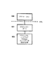
図4aは、一時的グラフィックス処理のためのメモリ・ロケーション(左及び右バックバッファ)の作成を示す。その場合、基本的には、追加のメモリ・ロケーションが追加される。即ち、(400)で右バッファが設定され、(401)でTDVision技術が存在するかどうかが弁別され、イエスの場合には、(402)で左バッファが設定され、(403)で終了する。TDVision技術が存在しないとき、(403)で処理は終了する。なぜなら、弁別すべきものが存在しないからである。 FIG. 4a shows the creation of memory locations (left and right back buffers) for temporary graphics processing. In that case, basically an additional memory location is added. That is, the right buffer is set at (400), and whether or not the TDVision technology exists is discriminated at (401). If yes, the left buffer is set at (402) and the process ends at (403). When the TDVision technology does not exist, the process ends at (403). This is because there is nothing to be distinguished.
図4bは、左カメラ及び右カメラ画像を弁別及び表示するフローチャートを示す。左観察画は(410)で設定され、画像はカメラ位置の関数として左バックバッファ内に描画される(411)。画像は左スクリーン内に表示され(412)、次に(413)でTDVisionフォーマットを有するかどうかが弁別される。イエスの場合、右観察画位置の座標が計算され(414)、画像は左カメラ位置の関数として右バックバッファ内に描画される(415)。次に、画像は右スクリーン内に表示され(416)、(413)の弁別が必要でなければ、処理は(417)で終了する。画像は現在の最新技術のフォーマットで提供されるので、サブルーチンは最終段階(417)へジャンプして終了する。なぜなら、他の座標を計算して並列情報を表示する必要はないからである。本願の新規な部分は、図5で示されるグラフィックス・プロセッシング・ユニット(GPUハードウェア)及びグラフィックス・エンジン(グラフィックス・エンジン、ソフトウェア)である。 FIG. 4b shows a flowchart for discriminating and displaying the left camera and right camera images. The left observation image is set at (410), and the image is drawn in the left back buffer as a function of the camera position (411). The image is displayed in the left screen (412) and then (413) it is discriminated whether it has the TDVision format. If yes, the coordinates of the right viewing image position are calculated (414) and the image is rendered in the right back buffer as a function of the left camera position (415). Next, the image is displayed in the right screen (416), and if the discrimination of (413) is not necessary, the process ends at (417). Since the image is provided in the current state of the art format, the subroutine jumps to the final stage (417) and ends. This is because it is not necessary to calculate other coordinates and display parallel information. The novel part of the present application is a graphics processing unit (GPU hardware) and a graphics engine (graphics engine, software) shown in FIG.
ハードウェアの修正は、次のとおりである。
− 左及び右バックバッファのためにRAMを増加する。
− 表示バッファ内で追加の独立表示デバイスを実現するが、埋没様式でメモリを共有するので、それは対応するバックバッファを取る。
The hardware modifications are as follows.
Increase RAM for left and right back buffers.
-Implement an additional independent display device in the display buffer, but since it shares memory in a buried manner, it takes a corresponding back buffer.
この場合、バックバッファのRAMメモリ及びビデオ・カードのフロントバッファが十分大きく、左及び右チャネルを同時にサポートすることが必要である。これは、各々が1024x768x4色深度バイトの深度を有する4つのバッファをサポートするため、最少で32MBを有することを必要とする。更に、ビデオ出力信号はデュアルであるか(2つのVGAポート)、多数のモニタを処理する能力を有する。なぜなら、2つの出力表示システム、即ち、選択するため1つはVGAであり1つはSビデオのポートを有するATI RADEON 9500(登録商標)カードの場合だからである。3Dバイザへ接続されるように、左−右チャネルごとに1秒間の表示当たり60フレームを満たすだけのデュアル出力を有するグラフィックス・カードが作成される。これらの出力は、SVGA、Sビデオ、RCA、又はDビデオタイプの出力である。 In this case, the RAM memory of the back buffer and the front buffer of the video card are sufficiently large, and it is necessary to support the left and right channels simultaneously. This requires having a minimum of 32 MB to support 4 buffers each having a depth of 1024x768x4 color depth bytes. In addition, the video output signal is dual (two VGA ports) or has the ability to process multiple monitors. This is because there are two output display systems, one for selection, VGA and one for ATI RADEON 9500® card with S-Video port. A graphics card is created that has dual outputs that only fill 60 frames per second display for each left-right channel so that it is connected to the 3D visor. These outputs are SVGA, S-video, RCA, or D-video type outputs.
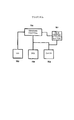
コンピューティング・スキームは、図5で示されるようにTDVコンパイレーションのために修正されて呈示される。即ち、CPU(50)、メモリ・ドライバ(52)、拡張メモリ(52)が示される。このメモリは、オーディオ・ドライバ(53)及びスピーカ(54)、更にディスク・ポート(56)及びユーザとのインタラクティブ要素(57)、例えば、マウス、キーボード、ゲームパッド、及びジョイスティックを制御する入力及び出力ドライバ(55)を導入する。他方では、グラフィックス・ドライバはモニタ(59)及び3次元バイザの3Dバイザ(59b)と直接インタラクトする。
The computing scheme is presented modified for TDV compilation as shown in FIG. That is, a CPU (50), a memory driver (52), and an extended memory (52) are shown. This memory includes inputs and outputs that control the audio driver (53) and speaker (54), as well as the disk port (56) and user interaction elements (57), eg, mouse, keyboard, gamepad, and joystick. Install the driver (55). On the other hand, the graphics driver interacts directly with the monitor (59) and the
グラフィックス・ハードウェア(HAL)に関して具体的には、TDVision技術で変更をコンパイルする必要がある。アプリケーション(500)は情報をグラフィックス・ドライバ(501)へ送り、グラフィックス・ハードウェア・サポートに起因する動作(502)は、TDVision技術で実際に物理的変更をコンパイルされる必要がある。OpenGL及びDirecTXによってTDVision技術を実現するためには、ビデオゲームのソフトウェア・セクション、及び前述したように、幾つかのハードウェア・セクションで修正を行うことが必要である。 Specifically for graphics hardware (HAL), changes need to be compiled with TDVision technology. The application (500) sends information to the graphics driver (501), and the operation (502) due to the graphics hardware support needs to be actually compiled with TDVision technology. In order to implement TDVision technology with OpenGL and DirecTX, it is necessary to make modifications in the software section of the video game and in some hardware sections as described above.
ソフトウェアに関しては、図6で示されるように、典型的な作業アルゴリズム内へ幾つかの特別の特性、及びTDVisionサブルーチンへの呼び出しを付加する必要がある。
− サーフェイス情報をロードする(600)。
− メッシュ情報をロードする(601)。
− TDVisionバックバッファを作成する(602)。その場合、左バックバッファはメモリ内に作成される。TDVision技術であれば、右バックバッファがメモリ内に作成される。
− 初期座標を適用する(603)。
− ゲーム論理を適用する(604)。
− 妥当性検証及び人工知能(605)。
− 位置の計算(606)。
− 衝突の検証(607)。
− TDVisionバックバッファ内で情報を描画し、オン・スクリーンで表示する(608)。その場合、右カメラ観察画を設定しなければならない。現在の右カメラ・ベクトルの関数として右バックバッファ内に画像を描画し、右スクリーン(フロントバッファ)の上に画像を表示する。TDVision技術であれば、左のペアの座標を計算し、左カメラ観察画を設定し、左カメラの現在のベクトルの関数として左バックバッファ内で画像を描画し、右スクリーン(フロントバッファ)の上に情報を表示する。これはハードウェアの修正を必要とする。
For software, it is necessary to add some special features and calls to the TDVision subroutine into the typical working algorithm, as shown in FIG.
-Load surface information (600).
-Load mesh information (601).
Create a TDVision back buffer (602). In that case, the left back buffer is created in memory. With TDVision technology, a right back buffer is created in memory.
-Apply initial coordinates (603).
-Apply game logic (604).
-Validation and artificial intelligence (605).
-Calculation of position (606).
-Collision verification (607).
-Draw information in the TDVision back buffer and display it on-screen (608). In that case, the right camera observation image must be set. Draw the image in the right back buffer as a function of the current right camera vector and display the image on the right screen (front buffer). With TDVision technology, the left pair of coordinates is calculated, the left camera view is set, the image is drawn in the left back buffer as a function of the left camera's current vector, and the top of the right screen (front buffer). To display information. This requires hardware modifications.
こうして、左眼及び右眼に対応する一対のバッファが作成される。これらは、ゲーム・ループ内で評価されたとき、下記で説明されるように、右カメラ(現在)及び左カメラ(SETXYZTDV関数で計算された補数)の各々の映像化に対応するベクトル座標を取得する。 Thus, a pair of buffers corresponding to the left eye and the right eye are created. When evaluated in the game loop, these get the vector coordinates corresponding to each visualization of the right camera (current) and the left camera (complement calculated with the SETXYZTDV function), as described below. To do.
言及することが重要な事項として、上記スクリーン出力バッファ又はフロントバッファは、最初からビデオ表示サーフェイス(デバイス・コンテキスト)又は問題のサーフェイス(サーフェイス)へ割り当てられるが、TDVisionの3Dバイザで情報を表示するためには、2つのビデオ出力、即ち、右出力(正規のVGA)及び左出力(追加のVGA、ディジタル補数、又はSビデオ)が物理的に存在し、TDVisionと互換的になることが必要である。例ではDirecTXが使用されるが、同じ処理及びコンセプトをOpenGLフォーマットへ適用することができる。
It is important to mention that the screen output buffer or front buffer is initially assigned to the video display surface (device context) or the problem surface (surface), but for displaying information on the
図7は、グラフィカル・アプリケーション通信インタフェースの表示ラインを実行するアルゴリズム(70)の概略を示す。実際には、バーテックス演算(77)と一緒に三角法(72)が使用され、画像が構成され(71)、コマンド(73)、表示リスト(74)、及びテクスチャを画像へ割り当てるメモリ(76)を介してピクセル演算又は画像要素(75)が使用され、結果として表示が演算(79)によってメモリ・フレーム(70F)へ送られる。Windowsソフトウェア(700)は(702)及びグラフィック言語カード(701)と通信し、グラフィック言語カードはグラフィック情報ライブラリを含み、グラフィック情報ライブラリは(703)及び(704)を導入するために有用である。 FIG. 7 shows an overview of the algorithm (70) for executing the display line of the graphical application communication interface. In practice, trigonometry (72) is used in conjunction with vertex operation (77) to construct an image (71), command (73), display list (74), and memory (76) to assign textures to the image. The pixel operation or image element (75) is used via and the resulting display is sent by the operation (79) to the memory frame (70F). Windows software (700) communicates with (702) and a graphic language card (701), the graphic language card includes a graphic information library, and the graphic information library is useful for implementing (703) and (704).
図8は、OpenGLアルゴリズム(80)を使用して、オブジェクトのために左及び右画像を表示するTDVision技術を示す。それはバックバッファをクリアし(81)、バックバッファのためにポインタを取得し(82)、バックバッファをクローズし(83)、シーンを再描画し(84)、バックバッファをオープンし(85)、パックバッファ・ポインタをアンロックし(86)、画像を左表示サーフェイスへ送る。(800)において、それはTDVision技術であるかどうかを弁別し、イエスの場合には、メモリをクリアし(801)、バックバッファのためにポインタを取得し(802)、バックバッファをクローズし(803)、新しいパースペクティブのために座標を取得し(804)、シーンを再描画し(805)、メモリをオープンし(806)、バックバッファ・ポインタをアンロックし(807)、画像を右表示サーフェイスへ送る(808)。 FIG. 8 shows a TDVision technique for displaying left and right images for an object using the OpenGL algorithm (80). It clears the back buffer (81), gets a pointer for the back buffer (82), closes the back buffer (83), redraws the scene (84), opens the back buffer (85), The pack buffer pointer is unlocked (86) and the image is sent to the left display surface. At 800, it is discriminated whether it is a TDVision technology, and if yes, the memory is cleared (801), a pointer is obtained for the back buffer (802), and the back buffer is closed (803). ), Get coordinates for the new perspective (804), redraw the scene (805), open the memory (806), unlock the backbuffer pointer (807), and move the image to the right display surface Send (808).
図9は、TDVision技術をコンパイルするためビデオ・カードで必要な変更(90)を示す。即ち、正規の左バックバッファ(91)が正規の左一次バックバッファ(92)に先行する。左一次バックバッファは、モニタのVGA出力(95)へ接続され、他のVGA出力を有しなければならない。したがって、それは右一次バックバッファ(94)を受け取ることができる。右一次バックバッファは、先行するTDVision技術バックバッファを有する。左及び右のバックバッファの双方は、バックバッファ(91)及び(93)によって送られた情報を受け取って表示するため、デュアルVGA入力を有する3Dバイザ(96)へ接続可能である。 FIG. 9 shows the changes (90) required on the video card to compile the TDVision technology. That is, the regular left back buffer (91) precedes the regular left primary back buffer (92). The left primary back buffer is connected to the monitor's VGA output (95) and must have another VGA output. Therefore, it can receive the right primary back buffer (94). The right primary back buffer has a preceding TDVision technology back buffer. Both the left and right backbuffers can be connected to a 3D visor (96) with dual VGA inputs to receive and display the information sent by the backbuffers (91) and (93).
このソフトウェア修正は、Direct X内で次のAPI関数を使用する。
TDVisionバックバッファの作成:
関数の作成 BACKBUFFERTDV()
左バッファ
d3dデバイスの設定 =
d3d.デバイス作成(D3Dアダプタ_デフォルト,_
D3Dデバイスタイプ_HAL,hWndL,_
D3D作成_ソフトウェア_バーテックス処理,
d3dpp)
If ゲームがTDVであれば、then
右バッファ
d3d右デバイスの設定 =
d3d.デバイス作成(D3Dアダプタ_デフォルト,_
D3Dデバイスタイプ_HAL,hWndR,_
D3D作成_ソフトウェア_バーテックス処理,
d3dpp2)
Ifの終了
サブルーチンの終了
TDVisionバックバッファ内で画像を描画する:
関数 DRAWBACKBUFFERTDV()
左シーンを描画する
d3dデバイス.シーンの開始
d3dデバイス.ストリームソースの設定0,ポリゴン1_vb,
長さ(ポリゴン1.v1)
d3dデバイス.プリミティブの描画
D3DPT_三角形リスト,0,1
d3dデバイス.シーンの終了
バックバッファをフロントバッファ、スクリーンへコピーする
D3dデバイス.値0,値0,値0の呈示
’フラグをチェックすることによって、TDVisionプログラムであるかどうかを検証する
IF ゲームがTDVであれば、THEN
’右カメラの座標を計算する
SETXYZTDV()
’右シーンを描画する
d3dデバイス2.シーンの開始
d3dデバイス2.ストリームソース0の設定,
ポリゴン2_vb,長さ(ポリゴン1,v1)
d3dデバイス2.プリミティブの描画
D3DPT_三角形リスト,0,1
d3dデバイス2.シーンの終了
d3dデバイス2.値0,値0,0,値の呈示
サブルーチンの終了
xyzカメラ・ベクトルの修正:
ベクトルカメラソース.z = z位置
D3DX行列ルック AtLH mat観察画,
ベクトルカメラソース,_
ベクトルカメラターゲット, ベクトル作成
(0,1,0)
D3dデバイス2.変換設定 D3DTS_観察画,
mat観察画
ベクトルカメラソース.x = x位置
D3DX行列ルック AtLH mat観察画,
ベクトルカメラソース,_
ベクトルカメラターゲット, ベクトル作成
(0,1,0)
D3dデバイス2.変換設定 D3DTS_観察画,
mat観察画
ベクトルカメラソース.y = y位置
D3DX行列ルック AtLH mat観察画,
ベクトルカメラソース,_
ベクトルカメラターゲット, ベクトル作成
(0,1,0)
D3dデバイス2.変換設定 D3DTS_観察画,
mat観察画
This software modification uses the following API function in Direct X:
Creating a TDVision back buffer:
Create function BACKBUFFERTDV ()
Left buffer d3d device setting =
d3d. Device creation (D3D adapter_default, _
D3D device type_HAL, hWndL, _
D3D creation_software_vertex processing,
d3dpp)
If the game is TDV, then
Right buffer d3d right device setting =
d3d. Device creation (D3D adapter_default, _
D3D device type_HAL, hWndR, _
D3D creation_software_vertex processing,
d3dpp2)
End of If End of subroutine
Draw an image in the TDVision back buffer:
Function DRAWBACKBUFFERTDV ()
D3d device to draw the left scene. Start of scene d3d device. Stream source setting 0, polygon 1_vb,
Length (Polygon 1.v1)
d3d device. Primitive drawing D3DPT_triangle list, 0, 1
d3d device. End of scene
Copy back buffer to front buffer, screen
D3d device. Verify whether it is a TDVision program by checking the '0, value 0, value 0 presentation' flag If the IF game is TDV, then
'Calculate the coordinates of the right camera SETXYZTDV ()
'Draw right scene d3d device 2. Start of scene d3d device 2. Setting stream source 0,
Polygon 2_vb, length (Polygon 1, v1)
d3d device2. Primitive drawing D3DPT_triangle list, 0, 1
d3d device2. End of scene d3d device Value 0, value 0, 0, value presentation End of subroutine
xyz camera vector correction:
Vector camera source. z = z position D3DX matrix look AtLH mat observation image,
Vector camera source, _
Vector camera target, vector creation (0, 1, 0)
1. D3d device Conversion setting D3DTS_observation image,
mat observation image Vector camera source. x = x position D3DX matrix look AtLH mat observation image,
Vector camera source, _
Vector camera target, vector creation (0, 1, 0)
1. D3d device Conversion setting D3DTS_observation image,
mat observation image Vector camera source. y = y position D3DX matrix look AtLH mat observation image,
Vector camera source, _
Vector camera target, vector creation (0, 1, 0)
1. D3d device Conversion setting D3DTS_observation image,
mat observation image
こうして、左眼及び右眼に対応する一対のバッファが作成される。これらは、ゲーム・ループ内で評価されたとき、通常の座標変換式によって、右カメラ及び左カメラの映像化に対応するベクトル座標(SETXYZTDV関数で計算された補数)を取得する。 Thus, a pair of buffers corresponding to the left eye and the right eye are created. When these are evaluated in the game loop, the vector coordinates (complement calculated by the SETXYZTDV function) corresponding to the imaging of the right camera and the left camera are acquired by a normal coordinate conversion formula.
言及することが重要な事項として、上記スクリーン出力バッファ又はフロントバッファは、最初からデバイス・コンテキスト又は問題のサーフェイスへ割り当てられるが、TDVisionの3Dバイザ内で情報を表示するためには、2つのビデオ出力、即ち、右出力(正規のVGA)及び左出力(追加のVGA、ディジタル補数、又はSビデオ)が物理的に存在して、TDVisionと互換的であることが必要である。
It is important to mention that the screen output buffer or front buffer is initially assigned to the device context or the surface in question, but in order to display information within the
例としてDirecTXを使用したが、図8で示されるOpenGLフォーマットのために同じ処理及びコンセプトを適用することができる。 Although DirecTX was used as an example, the same processing and concept can be applied for the OpenGL format shown in FIG.
この場合、バックバッファのRAMメモリ及びビデオ・カードのフロントバッファが、左及び右のチャネルを同時にサポートするほど十分に大きいことが必要である。これは、最小で32MBを有して、各々が1024x768x4バイトの色深度を有する4つのバックバッファをサポートする必要がある。前述したように、ビデオ出力信号はデュアル(2つのVGAポート)であるか、複数のモニタを処理する能力を有していなければならない。なぜなら、それはATI RADEON 9500(登録商標)カードの場合だからである。このカードは2つの出力表示システム、即ち、1つのVGA及び1つのSビデオ及び1つのDビデオ・ポートを有し、それらから選択される。 In this case, the RAM memory of the back buffer and the front buffer of the video card need to be large enough to support the left and right channels simultaneously. This needs to support 4 back buffers with a minimum of 32MB, each with a color depth of 1024x768x4 bytes. As mentioned above, the video output signal must be dual (two VGA ports) or capable of processing multiple monitors. This is because it is an ATI RADEON 9500 (registered trademark) card. This card has and is selected from two output display systems: one VGA and one S-video and one D-video port.
グラフィックス・カードが作成される。このカードは、3Dバイザへ接続されるように左−右チャネル当たり1秒間の表示につき60フレームを満たすだけのデュアル出力を有する。これらの出力はSVGA、Sビデオ、RCA、又はDビデオ・タイプの出力であってもよい。 A graphics card is created. This card has a dual output that only fills 60 frames per second display per left-right channel for connection to a 3D visor. These outputs may be SVGA, S-video, RCA, or D-video type outputs.
したがって、カメラの左及び右のパースペクティブの双方から見た対応画像を得ることができ、ハードウェアは2つの異なった独立ビデオ出力で表示される情報を認識し、リアルタイムの多重化及び表示は行われない。現在、全ての技術は多重化及びソフトウェア・シミュレーションを使用する。本願によって提案される技術では、リアルの情報を取得することができ、3Dバイザを使用する間、2つの異なったパースペクティブから画像を表示することができ、脳は、スクリーン上のフリッカ及び現在の最新技術に関連した作用を起こすことなく、画像が空間内で占める体積を連想する。 Thus, corresponding images seen from both the left and right perspectives of the camera can be obtained, the hardware recognizes the information displayed in two different independent video outputs, and real-time multiplexing and display is performed. Absent. Currently, all technologies use multiplexing and software simulation. With the technology proposed by the present application, real information can be obtained and images can be displayed from two different perspectives while using the 3D visor, the brain flickers on the screen and the current latest Reminiscent of the volume that an image occupies in space without causing a technology-related effect.
二次立体カメラの座標計算方法(SETXYZTDV())は、ソフトウェア・プログラムにおけるアニメーション、表示、及びモデリングによって、立体画像を生成する3次元コンピュータ映像システムを取得させる。この方法は、空間座標(x,y,z)を取得させる。この空間座標は、ソフトウェア・プログラムの使用によって立体映像を取得するため、2つのコンピュータ生成仮想映像化カメラへ割り当てられなければならない。ソフトウェア・プログラムは3次元をシミュレートし、オブジェクトの移動によって、又はその時点でコンピュータ生成オブジェクト、例えば、Autocad、Micrografix Simply 3D、3Dmax Studio、Point、Dark Basic、Maya、Marionette、Blender、Excel、Word、Paint、Power、Corel Draw、Photo paint、Photoshopなどによって観察された「仮想カメラ」の移動によって、画像を生成する。しかし、これらのプログラムの全ては、1つの固定又は移動パースペクティブを有する1つのカメラだけを表示するように設計される。 The secondary stereo camera coordinate calculation method (SETXYZTDV ()) obtains a three-dimensional computer video system that generates a stereo image through animation, display, and modeling in a software program. This method causes the spatial coordinates (x, y, z) to be acquired. This spatial coordinate must be assigned to two computer-generated virtual imaging cameras in order to obtain a stereoscopic image by using a software program. The software program simulates 3D, and by moving the object or at that time computer generated objects such as Autocad, Microfix Simply 3D, 3Dmax Studio, Point, Dark Basic, Maya, Marionete, Blender, Excel, Word, An image is generated by movement of a “virtual camera” observed by Paint, Power, Corel Draw, Photo paint, Photoshop, and the like. However, all of these programs are designed to display only one camera with one fixed or moving perspective.
座標変換式、即ち、次式によって、追加の3Dモデリング及びアニメーション特性が前のプログラムへ付加される。
x = x’cos φ − y’sin φ
y = x’sin φ + y’cos φ
Additional 3D modeling and animation characteristics are added to the previous program by the coordinate transformation equation, ie:
x = x'cos φ-y'sin φ
y = x'sin φ + y'cos φ
第1のカメラへ直接リンクされた第2又は二次カメラについて、正確な位置が計算される。この手段によって、人間の立体映像パースペクティブをシミュレートする異なったパースペクティブから、2つの同時画像が取得される。この手順は、アルゴリズムによって、二次カメラの位置をリアルタイムで計算し、それを適切な位置に置き、座標変換式を使用して達成されるように、第2のカメラのモデリング画像及び表現を取得し、カメラを原点へ移動し、二次カメラとオブジェクト又は対象との間の角度及び距離が計算され、次に一次カメラ、対象、及び二次カメラが、取得された位置に再配置される。次に、7つのパラメータを知る必要がある。即ち、元の座標系における一次カメラの第1の座標(Xp,Yp,Zp)、第4のパラメータとしての眼の平均分離距離(6.5〜7.0cm)、及びカメラによって観察された対象位置の3つの座標である。 For a second or secondary camera that is directly linked to the first camera, the exact position is calculated. By this means, two simultaneous images are obtained from different perspectives simulating a human stereoscopic video perspective. This procedure allows the algorithm to calculate the secondary camera position in real time, place it in the appropriate position, and obtain a modeling image and representation of the second camera as achieved using the coordinate transformation formula The camera is then moved to the origin, the angle and distance between the secondary camera and the object or target is calculated, and then the primary camera, target and secondary camera are relocated to the acquired position. Next, it is necessary to know seven parameters. That is, the first coordinates (X p , Y p , Z p ) of the primary camera in the original coordinate system, the average separation distance (6.5 to 7.0 cm) of the eye as the fourth parameter, and observation by the camera These are the three coordinates of the target position.
出力パラメータは、同じ対象点を観察している二次カメラの座標、即ち(Xs,Ys,Zs)であって、これは下記のステップから取得される。
− 元の座標系における一次カメラの座標(Xp,Yp,Zp)を知る。
対象の座標(xt,yt,zt)を知る。
− 「x」及び「z」座標のみが変換される。なぜなら、カメラの座標及び/又は高さは一定だからである(観察者にとって、映像偏向は存在しない)。
The output parameter is the coordinates of the secondary camera observing the same object point, ie (X s , Y s , Z s ), which is obtained from the following steps.
- coordinates of the primary camera in the original coordinate system (X p, Y p, Z p) to know.
Know the coordinates (xt, yt, zt) of the object.
-Only "x" and "z" coordinates are transformed. This is because the camera coordinates and / or height are constant (there is no image deflection for the observer).
一次カメラの座標は(0,ys,0)位置へ移動される。 The coordinates of the primary camera are moved to the (0, ys, 0) position.
対象も平行移動される。 The object is also translated.
カメラと対象を接続するラインの勾配が計算される。 The slope of the line connecting the camera and the object is calculated.
軸と、一次カメラ及び対象を結合するベクトルとの間の角度が作成される。 An angle is created between the axis and the vector connecting the primary camera and the object.
角度計算で特別な考慮を払うため、それが属する象限は逆タンジェント関数によって類別される。 The quadrant to which it belongs is categorized by the inverse tangent function to give special consideration to the angle calculation.
座標系の全体を、その軸から、軸とベクトルとの間の同じ角度で回転することによって、新しい座標が取得される。オブジェクトが「z」軸の上に置かれ、新しい座標系の原点に一次カメラが残る新しい座標系が取得される。 New coordinates are obtained by rotating the entire coordinate system from its axis at the same angle between the axis and the vector. An object is placed on the “z” axis, and a new coordinate system is obtained that leaves the primary camera at the origin of the new coordinate system.
人間の眼の平均距離位置に二次カメラを置くことによって、二次カメラの座標が取得される。 By placing the secondary camera at the average distance position of the human eye, the coordinates of the secondary camera are obtained.
これらの座標は、同じ初期角で回転される。 These coordinates are rotated with the same initial angle.
「x」及び「z」オフセットが加えられる。最初、これらは一次カメラを原点へ移動するために減じられた。 “X” and “z” offsets are added. Initially these were subtracted to move the primary camera to the origin.
最後に、これらの2つの新しいXs y Zs座標が二次カメラへ割り当てられ、yp座標が維持される。これは二次カメラへ割り当てられる最終の座標点(Xs,Yp,Zs)の同じ値のために高さを決定する。 Finally, these two new X s y Z s coordinates are assigned to the secondary camera and the yp coordinates are maintained. This determines the height for the same value of the final coordinate point (X s , Y p , Z s ) assigned to the secondary camera.
手順は、Delphi、C、C++、Visual C++、Omnisなどの言語で実現可能であるが、結果は同じになるであろう。 The procedure can be implemented in languages such as Delphi, C, C ++, Visual C ++, Omnis, but the results will be the same.
このアルゴリズムの一般化されたアプリケーションは、二次カメラの位置をリアルタイムで取得する必要がある任意のプログラムで使用されるであろう。 A generalized application of this algorithm would be used in any program that needs to obtain the secondary camera position in real time.
このアルゴリズムは、2次元を処理するが立体映像アプリケーションのために開発された既存のソフトウェアで実現されなければならない。 This algorithm processes two dimensions but must be implemented with existing software developed for stereoscopic video applications.
本発明の具体的な実施形態が図示及び説明された。本発明の範囲を逸脱することなく、幾つかの修正又は変更を行い得ることが、当業者に明らかであろう。添付のクレイムは、全ての変更及び修正が本発明の範囲内にあるように前述した情報をカバーすることを意図する。 Specific embodiments of the invention have been shown and described. It will be apparent to those skilled in the art that several modifications or variations can be made without departing from the scope of the invention. The appended claims are intended to cover the above information so that all changes and modifications are within the scope of the present invention.
Claims (5)
左バックバッファおよび右バックバッファを用意する用意ステップと、
ビデオゲームにおけるオブジェクトの第1の視野に対応する第1の画像を前記左バックバッファに格納する第1格納ステップと、
前記オブジェクトの第2の視野の高さに偏向が発生しないようにx座標およびz座標のみを計算することで前記第1の画像の前記第2の視野の三次元空間における位置座標を計算する計算ステップと、
計算された前記位置座標に基づいて前記オブジェクトの第2の視野画像を決定する決定ステップと、
前記右バックバッファに前記第2の視野画像を格納する第2格納ステップと、
前記ビデオゲーム・システムからユーザに三次元の像を提供するために前記ユーザに対して前記第1の画像および前記第2の視野画像を表示する表示ステップと、
を含む方法。A computer-implemented method in a video game system for displaying 3D images, comprising:
A preparation step of preparing a left back buffer and a right back buffer;
A first storing step of storing in the left back buffer a first image corresponding to a first field of view of an object in a video game ;
Calculation to calculate the position coordinates in the three-dimensional space of the second field of the first image by calculating only the second height deflection x and z coordinates so as not to generate a field of view of the object Steps,
A determining step for determining a second field-of-view image of the object based on the calculated position coordinates;
A second storing step of storing the second visual field image in the right back buffer;
Displaying the first image and the second field of view image to the user to provide a three-dimensional image to the user from the video game system ;
Including methods.
請求項1に記載の方法。The first image corresponds to a first object in the video game;
The method of claim 1.
請求項1に記載の方法。The calculating step includes calculating coordinates of a viewpoint of a right-eye camera;
The method of claim 1.
請求項1に記載の方法。The calculating step includes a step of acquiring a spatial coordinate by a coordinate conversion formula given a position of a first virtual camera corresponding to the first visual field.
The method of claim 1.
請求項1に記載の方法。The displaying step includes generating a left image and a right image of different video channels;
The method of claim 1.
Applications Claiming Priority (1)
| Application Number | Priority Date | Filing Date | Title |
|---|---|---|---|
| PCT/MX2003/000112 WO2005059842A1 (en) | 2003-12-19 | 2003-12-19 | 3d videogame system |
Related Child Applications (1)
| Application Number | Title | Priority Date | Filing Date |
|---|---|---|---|
| JP2011169529A Division JP5236051B2 (en) | 2011-08-02 | 2011-08-02 | 3D video game system |
Publications (2)
| Publication Number | Publication Date |
|---|---|
| JP2007528518A JP2007528518A (en) | 2007-10-11 |
| JP4841250B2 true JP4841250B2 (en) | 2011-12-21 |
Family
ID=34699036
Family Applications (1)
| Application Number | Title | Priority Date | Filing Date |
|---|---|---|---|
| JP2005512205A Expired - Fee Related JP4841250B2 (en) | 2003-12-19 | 2003-12-19 | 3D video game system |
Country Status (11)
| Country | Link |
|---|---|
| US (6) | US7666096B2 (en) |
| EP (1) | EP1727093A1 (en) |
| JP (1) | JP4841250B2 (en) |
| KR (2) | KR101101570B1 (en) |
| CN (1) | CN100456328C (en) |
| AU (1) | AU2003291772A1 (en) |
| BR (1) | BR0318661A (en) |
| CA (1) | CA2550512C (en) |
| HK (1) | HK1103153A1 (en) |
| MX (1) | MXPA06007015A (en) |
| WO (1) | WO2005059842A1 (en) |
Families Citing this family (39)
| Publication number | Priority date | Publication date | Assignee | Title |
|---|---|---|---|---|
| US8253729B1 (en) * | 1983-05-09 | 2012-08-28 | Geshwind David M | Trimming depth buffer during 2D to 3D conversion |
| US9958934B1 (en) | 2006-05-01 | 2018-05-01 | Jeffrey D. Mullen | Home and portable augmented reality and virtual reality video game consoles |
| EP2144556A4 (en) * | 2007-05-10 | 2012-02-22 | Burdea Grigore | Periodic evaluation and telerehabilitation systems and methods |
| US7884823B2 (en) * | 2007-06-12 | 2011-02-08 | Microsoft Corporation | Three dimensional rendering of display information using viewer eye coordinates |
| AU2008202315A1 (en) * | 2007-06-14 | 2009-01-08 | Aristocrat Technologies Australia Pty Limited | A method of providing a player interface in a gaming system |
| JP2009245349A (en) * | 2008-03-31 | 2009-10-22 | Namco Bandai Games Inc | Position detection system, program, information recording medium, and image generating device |
| US8487927B2 (en) * | 2008-05-19 | 2013-07-16 | Microsoft Corporation | Validating user generated three-dimensional models |
| US9324173B2 (en) | 2008-07-17 | 2016-04-26 | International Business Machines Corporation | System and method for enabling multiple-state avatars |
| US8957914B2 (en) | 2008-07-25 | 2015-02-17 | International Business Machines Corporation | Method for extending a virtual environment through registration |
| US10166470B2 (en) | 2008-08-01 | 2019-01-01 | International Business Machines Corporation | Method for providing a virtual world layer |
| CN101599182B (en) * | 2009-07-29 | 2012-10-03 | 威盛电子股份有限公司 | Three-dimensional object rotating method, and corresponding computer system thereof |
| US20110055888A1 (en) * | 2009-08-31 | 2011-03-03 | Dell Products L.P. | Configurable television broadcast receiving system |
| US8619122B2 (en) * | 2010-02-02 | 2013-12-31 | Microsoft Corporation | Depth camera compatibility |
| JP5800501B2 (en) | 2010-03-12 | 2015-10-28 | 任天堂株式会社 | Display control program, display control apparatus, display control system, and display control method |
| US9128298B2 (en) * | 2010-04-05 | 2015-09-08 | Sharp Kabushiki Kaisha | Three-dimensional image display apparatus, display system, driving method, driving apparatus, display controlling method, display controlling apparatus, program, and computer-readable recording medium |
| US10786736B2 (en) * | 2010-05-11 | 2020-09-29 | Sony Interactive Entertainment LLC | Placement of user information in a game space |
| US8786674B2 (en) | 2010-11-26 | 2014-07-22 | Mediatek Singapore Pte. Ltd. | Method for performing video display control within a video display system, and associated video processing circuit and video display system |
| CN104717484B (en) * | 2010-11-26 | 2017-06-09 | 联发科技(新加坡)私人有限公司 | Carry out method, video processing circuits and the video display system of video display control |
| CN102611899B (en) * | 2011-01-25 | 2014-11-05 | 上海渐华科技发展有限公司 | Three-dimensional video game information processing method and device based on OPENGLES platform |
| US8866898B2 (en) | 2011-01-31 | 2014-10-21 | Microsoft Corporation | Living room movie creation |
| TWI486052B (en) * | 2011-07-05 | 2015-05-21 | Realtek Semiconductor Corp | Three-dimensional image processing device and three-dimensional image processing method |
| US9342817B2 (en) | 2011-07-07 | 2016-05-17 | Sony Interactive Entertainment LLC | Auto-creating groups for sharing photos |
| US9189880B2 (en) | 2011-07-29 | 2015-11-17 | Synaptics Incorporated | Rendering and displaying a three-dimensional object representation |
| KR101917630B1 (en) | 2011-10-28 | 2018-11-13 | 매직 립, 인코포레이티드 | System and method for augmented and virtual reality |
| CN103150756A (en) * | 2012-02-22 | 2013-06-12 | 林善红 | Digital city three dimensional (3D) active stereo display system and manufacture method thereof |
| TWI489856B (en) * | 2012-09-03 | 2015-06-21 | Dimensional image processing method | |
| CN102881271A (en) * | 2012-09-29 | 2013-01-16 | 深圳市华星光电技术有限公司 | Method and system for driving liquid crystal display device |
| CN103942987B (en) * | 2014-05-09 | 2016-09-07 | 山东建筑大学 | Solid figure spatial vision memory training method |
| CN103942985B (en) * | 2014-05-09 | 2016-09-28 | 山东建筑大学 | Common items is utilized to carry out the method and device of visual memory training |
| CN103942983B (en) * | 2014-05-09 | 2016-09-07 | 山东建筑大学 | Chinese character visual memory training method and device |
| CN103942984B (en) * | 2014-05-09 | 2016-08-03 | 山东建筑大学 | Color vision memory training device |
| CN104113704A (en) * | 2014-07-01 | 2014-10-22 | 深圳市欢创科技有限公司 | Game image processing method and device |
| US9599821B2 (en) | 2014-08-08 | 2017-03-21 | Greg Van Curen | Virtual reality system allowing immersion in virtual space to consist with actual movement in actual space |
| US9779633B2 (en) | 2014-08-08 | 2017-10-03 | Greg Van Curen | Virtual reality system enabling compatibility of sense of immersion in virtual space and movement in real space, and battle training system using same |
| CN106354247A (en) * | 2015-07-17 | 2017-01-25 | 上海乐相科技有限公司 | Display control method and device for headset intelligent glasses |
| US10290149B2 (en) * | 2016-04-08 | 2019-05-14 | Maxx Media Group, LLC | System, method and software for interacting with virtual three dimensional images that appear to project forward of or above an electronic display |
| EP3577896A4 (en) | 2017-02-03 | 2020-11-25 | Warner Bros. Entertainment Inc. | Rendering extended video in virtual reality |
| CN108211354A (en) * | 2017-12-29 | 2018-06-29 | 网易(杭州)网络有限公司 | The generation method and device of virtual resource in 3D scene of game |
| TWI779336B (en) * | 2020-08-24 | 2022-10-01 | 宏碁股份有限公司 | Display system and method of displaying autostereoscopic image |
Citations (9)
| Publication number | Priority date | Publication date | Assignee | Title |
|---|---|---|---|---|
| JPH02109493A (en) * | 1988-10-18 | 1990-04-23 | Nec Corp | Stereoscopic display device |
| JPH07296185A (en) * | 1994-04-28 | 1995-11-10 | Canon Inc | Three-dimensional image display device |
| JPH08149519A (en) * | 1994-11-25 | 1996-06-07 | Matsushita Electric Works Ltd | Video image stereoscopic vision device |
| JPH09139957A (en) * | 1995-11-14 | 1997-05-27 | Mitsubishi Electric Corp | Graphic display device |
| JPH09237353A (en) * | 1995-12-29 | 1997-09-09 | Sega Enterp Ltd | Stereoscopic image system, method therefor, game machine and recording medium |
| JPH117275A (en) * | 1997-04-30 | 1999-01-12 | Hewlett Packard Co <Hp> | Device for generating left/right video channels |
| JP2000020757A (en) * | 1998-06-30 | 2000-01-21 | Mr System Kenkyusho:Kk | Stereoscopic image processor and user interface device and method for controlling buffer for stereoscopic display and device therefor and stereoscopic image display device and program-storage medium |
| JP2002519792A (en) * | 1998-06-30 | 2002-07-02 | コーニンクレッカ フィリップス エレクトロニクス エヌ ヴィ | Filter for transforming 3D data in hardware accelerated rendering architecture |
| JP2003067784A (en) * | 2002-07-30 | 2003-03-07 | Canon Inc | Information processor |
Family Cites Families (65)
| Publication number | Priority date | Publication date | Assignee | Title |
|---|---|---|---|---|
| US4559555A (en) * | 1982-02-24 | 1985-12-17 | Arnold Schoolman | Stereoscopic remote viewing system |
| US4925294A (en) * | 1986-12-17 | 1990-05-15 | Geshwind David M | Method to convert two dimensional motion pictures for three-dimensional systems |
| US4825393A (en) * | 1986-04-23 | 1989-04-25 | Hitachi, Ltd. | Position measuring method |
| JPS62293381A (en) * | 1986-06-11 | 1987-12-19 | Toshiba Corp | Stereoscopic picture display device |
| US4962422A (en) * | 1988-06-23 | 1990-10-09 | Kabushiki Kaisha Topcon | Stereoscopic image display apparatus |
| EP0473343B1 (en) | 1990-08-20 | 1995-11-22 | Sony Corporation | Direct viewing picture image display apparatus |
| US5751927A (en) * | 1991-03-26 | 1998-05-12 | Wason; Thomas D. | Method and apparatus for producing three dimensional displays on a two dimensional surface |
| WO1993022699A1 (en) * | 1992-04-24 | 1993-11-11 | Depth Enhancement Inc | Three-dimensional visualization by altered multiple two-dimensional perspective imagery |
| US5467104A (en) | 1992-10-22 | 1995-11-14 | Board Of Regents Of The University Of Washington | Virtual retinal display |
| US5430474A (en) * | 1993-11-24 | 1995-07-04 | Hines; Stephen P. | Autostereoscopic imaging system |
| US5510832A (en) * | 1993-12-01 | 1996-04-23 | Medi-Vision Technologies, Inc. | Synthesized stereoscopic imaging system and method |
| US5523886A (en) | 1994-01-04 | 1996-06-04 | Sega Of America, Inc. | Stereoscopic/monoscopic video display system |
| US5694530A (en) * | 1994-01-18 | 1997-12-02 | Hitachi Medical Corporation | Method of constructing three-dimensional image according to central projection method and apparatus for same |
| KR100358021B1 (en) * | 1994-02-01 | 2003-01-24 | 산요 덴키 가부시키가이샤 | Method of converting 2D image into 3D image and stereoscopic image display system |
| JPH07222866A (en) * | 1994-02-09 | 1995-08-22 | Terumo Corp | Stereoscopic image game machine |
| JP3603285B2 (en) * | 1994-07-21 | 2004-12-22 | 株式会社セガ | Image processing device |
| US5986667A (en) * | 1994-12-22 | 1999-11-16 | Apple Computer, Inc. | Mechanism for rendering scenes using an object drawing subsystem |
| KR100414629B1 (en) | 1995-03-29 | 2004-05-03 | 산요덴키가부시키가이샤 | 3D display image generation method, image processing method using depth information, depth information generation method |
| US5729471A (en) | 1995-03-31 | 1998-03-17 | The Regents Of The University Of California | Machine dynamic selection of one video camera/image of a scene from multiple video cameras/images of the scene in accordance with a particular perspective on the scene, an object in the scene, or an event in the scene |
| US6175371B1 (en) * | 1995-06-02 | 2001-01-16 | Philippe Schoulz | Process for transforming images into stereoscopic images, images and image series obtained by this process |
| US6005607A (en) * | 1995-06-29 | 1999-12-21 | Matsushita Electric Industrial Co., Ltd. | Stereoscopic computer graphics image generating apparatus and stereoscopic TV apparatus |
| US5905499A (en) * | 1995-07-05 | 1999-05-18 | Fakespace, Inc. | Method and system for high performance computer-generated virtual environments |
| JP3544268B2 (en) * | 1995-10-09 | 2004-07-21 | 任天堂株式会社 | Three-dimensional image processing apparatus and image processing method using the same |
| US6331856B1 (en) * | 1995-11-22 | 2001-12-18 | Nintendo Co., Ltd. | Video game system with coprocessor providing high speed efficient 3D graphics and digital audio signal processing |
| JPH09167253A (en) * | 1995-12-14 | 1997-06-24 | Olympus Optical Co Ltd | Image display device |
| EP0809913B1 (en) * | 1995-12-19 | 2002-06-12 | Koninklijke Philips Electronics N.V. | Parallactic depth-dependent pixel shifts |
| US5867210A (en) * | 1996-02-09 | 1999-02-02 | Rod; Samuel R. | Stereoscopic on-screen surgical microscope systems |
| US5801717A (en) * | 1996-04-25 | 1998-09-01 | Microsoft Corporation | Method and system in display device interface for managing surface memory |
| US5877840A (en) * | 1996-09-20 | 1999-03-02 | Sanyo Electric Co., Ltd. | Binocular view function inspecting apparatus and inspecting method |
| JP3397602B2 (en) * | 1996-11-11 | 2003-04-21 | 富士通株式会社 | Image display apparatus and method |
| JP3723301B2 (en) * | 1996-11-21 | 2005-12-07 | 任天堂株式会社 | Image creation device, image display device, and game device |
| US5867621A (en) * | 1997-04-23 | 1999-02-02 | Siecor Corporation | Adapter and guide pin assembly for coupling of fiber optic connectors |
| US5982375A (en) * | 1997-06-20 | 1999-11-09 | Sun Microsystems, Inc. | Floating point processor for a three-dimensional graphics accelerator which includes single-pass stereo capability |
| US6501468B1 (en) * | 1997-07-02 | 2002-12-31 | Sega Enterprises, Ltd. | Stereoscopic display device and recording media recorded program for image processing of the display device |
| US6031564A (en) * | 1997-07-07 | 2000-02-29 | Reveo, Inc. | Method and apparatus for monoscopic to stereoscopic image conversion |
| US6108029A (en) * | 1997-08-22 | 2000-08-22 | Lo; Allen Kwok Wah | Dual-mode 2D/3D display system |
| AUPO894497A0 (en) * | 1997-09-02 | 1997-09-25 | Xenotech Research Pty Ltd | Image processing method and apparatus |
| JPH11151376A (en) * | 1997-11-20 | 1999-06-08 | Nintendo Co Ltd | Video game device and its storage medium |
| JP2002503855A (en) * | 1998-02-17 | 2002-02-05 | サン・マイクロシステムズ・インコーポレーテッド | Graphics system with variable resolution supersampling |
| US6496187B1 (en) * | 1998-02-17 | 2002-12-17 | Sun Microsystems, Inc. | Graphics system configured to perform parallel sample to pixel calculation |
| GB2336963A (en) | 1998-05-02 | 1999-11-03 | Sharp Kk | Controller for three dimensional display and method of reducing crosstalk |
| EP1008957A1 (en) * | 1998-06-02 | 2000-06-14 | Sony Corporation | Image processing device and image processing method |
| JP4149037B2 (en) * | 1998-06-04 | 2008-09-10 | オリンパス株式会社 | Video system |
| US6515662B1 (en) * | 1998-07-16 | 2003-02-04 | Canon Kabushiki Kaisha | Computer apparatus for providing stereoscopic views from monographic images and method |
| US6388666B1 (en) * | 1998-10-27 | 2002-05-14 | Imax Corporation | System and method for generating stereoscopic image data |
| US6816158B1 (en) * | 1998-10-30 | 2004-11-09 | Lemelson Jerome H | Three-dimensional display system |
| US6583793B1 (en) * | 1999-01-08 | 2003-06-24 | Ati International Srl | Method and apparatus for mapping live video on to three dimensional objects |
| US6559844B1 (en) * | 1999-05-05 | 2003-05-06 | Ati International, Srl | Method and apparatus for generating multiple views using a graphics engine |
| JP3619063B2 (en) * | 1999-07-08 | 2005-02-09 | キヤノン株式会社 | Stereoscopic image processing apparatus, method thereof, stereoscopic parameter setting apparatus, method thereof and computer program storage medium |
| KR100381817B1 (en) * | 1999-11-17 | 2003-04-26 | 한국과학기술원 | Generating method of stereographic image using Z-buffer |
| US6466208B1 (en) * | 1999-12-20 | 2002-10-15 | Silicon Integrated Systems Corporation | Apparatus and method for adjusting 3D stereo video transformation |
| US7254265B2 (en) * | 2000-04-01 | 2007-08-07 | Newsight Corporation | Methods and systems for 2D/3D image conversion and optimization |
| WO2001097531A2 (en) * | 2000-06-12 | 2001-12-20 | Vrex, Inc. | Electronic stereoscopic media delivery system |
| US6753828B2 (en) * | 2000-09-25 | 2004-06-22 | Siemens Corporated Research, Inc. | System and method for calibrating a stereo optical see-through head-mounted display system for augmented reality |
| US20020154214A1 (en) | 2000-11-02 | 2002-10-24 | Laurent Scallie | Virtual reality game system using pseudo 3D display driver |
| US6985162B1 (en) | 2000-11-17 | 2006-01-10 | Hewlett-Packard Development Company, L.P. | Systems and methods for rendering active stereo graphical data as passive stereo |
| JP2002157607A (en) | 2000-11-17 | 2002-05-31 | Canon Inc | System and method for image generation, and storage medium |
| US6765572B2 (en) * | 2001-04-23 | 2004-07-20 | Koninklijke Philips Electronics N.V. | Virtual modeling by voxel-clipping shadow-cast |
| US6759998B2 (en) * | 2001-10-19 | 2004-07-06 | Intel Corporation | Method and apparatus for generating a three-dimensional image on an electronic display device |
| US6760034B2 (en) | 2001-10-30 | 2004-07-06 | Emagin Corporation | Three dimensional display emulation method and system |
| KR20030049642A (en) * | 2001-12-17 | 2003-06-25 | 한국전자통신연구원 | Camera information coding/decoding method for composition of stereoscopic real video and computer graphic |
| US20030152264A1 (en) * | 2002-02-13 | 2003-08-14 | Perkins Christopher H. | Method and system for processing stereoscopic images |
| US7219352B2 (en) * | 2002-04-15 | 2007-05-15 | Microsoft Corporation | Methods and apparatuses for facilitating processing of interlaced video images for progressive video displays |
| US7427996B2 (en) * | 2002-10-16 | 2008-09-23 | Canon Kabushiki Kaisha | Image processing apparatus and image processing method |
| WO2005059699A2 (en) * | 2003-12-15 | 2005-06-30 | Quantum Matrix Holdings, Llc | System and method for multi-dimensional organization, management, and manipulation of data |
-
2003
- 2003-12-19 EP EP03768395A patent/EP1727093A1/en not_active Ceased
- 2003-12-19 JP JP2005512205A patent/JP4841250B2/en not_active Expired - Fee Related
- 2003-12-19 CA CA2550512A patent/CA2550512C/en not_active Expired - Fee Related
- 2003-12-19 KR KR1020117002821A patent/KR101101570B1/en active IP Right Grant
- 2003-12-19 KR KR1020067014543A patent/KR101041723B1/en active IP Right Grant
- 2003-12-19 BR BRPI0318661-0A patent/BR0318661A/en not_active Application Discontinuation
- 2003-12-19 WO PCT/MX2003/000112 patent/WO2005059842A1/en active Application Filing
- 2003-12-19 CN CNB2003801110475A patent/CN100456328C/en not_active Expired - Fee Related
- 2003-12-19 AU AU2003291772A patent/AU2003291772A1/en not_active Abandoned
-
2006
- 2006-06-19 US US11/471,280 patent/US7666096B2/en not_active Expired - Lifetime
- 2006-06-19 MX MXPA06007015A patent/MXPA06007015A/en not_active Application Discontinuation
-
2007
- 2007-07-16 HK HK07107581.3A patent/HK1103153A1/en not_active IP Right Cessation
-
2010
- 2010-02-22 US US12/710,191 patent/US8206218B2/en active Active
-
2012
- 2012-06-21 US US13/529,718 patent/US20120264515A1/en not_active Abandoned
-
2014
- 2014-01-23 US US14/162,592 patent/US20140307069A1/en not_active Abandoned
-
2016
- 2016-04-05 US US15/090,897 patent/US20170056770A1/en not_active Abandoned
-
2020
- 2020-02-19 US US16/795,237 patent/US20210008449A1/en not_active Abandoned
Patent Citations (9)
| Publication number | Priority date | Publication date | Assignee | Title |
|---|---|---|---|---|
| JPH02109493A (en) * | 1988-10-18 | 1990-04-23 | Nec Corp | Stereoscopic display device |
| JPH07296185A (en) * | 1994-04-28 | 1995-11-10 | Canon Inc | Three-dimensional image display device |
| JPH08149519A (en) * | 1994-11-25 | 1996-06-07 | Matsushita Electric Works Ltd | Video image stereoscopic vision device |
| JPH09139957A (en) * | 1995-11-14 | 1997-05-27 | Mitsubishi Electric Corp | Graphic display device |
| JPH09237353A (en) * | 1995-12-29 | 1997-09-09 | Sega Enterp Ltd | Stereoscopic image system, method therefor, game machine and recording medium |
| JPH117275A (en) * | 1997-04-30 | 1999-01-12 | Hewlett Packard Co <Hp> | Device for generating left/right video channels |
| JP2000020757A (en) * | 1998-06-30 | 2000-01-21 | Mr System Kenkyusho:Kk | Stereoscopic image processor and user interface device and method for controlling buffer for stereoscopic display and device therefor and stereoscopic image display device and program-storage medium |
| JP2002519792A (en) * | 1998-06-30 | 2002-07-02 | コーニンクレッカ フィリップス エレクトロニクス エヌ ヴィ | Filter for transforming 3D data in hardware accelerated rendering architecture |
| JP2003067784A (en) * | 2002-07-30 | 2003-03-07 | Canon Inc | Information processor |
Also Published As
| Publication number | Publication date |
|---|---|
| US8206218B2 (en) | 2012-06-26 |
| EP1727093A1 (en) | 2006-11-29 |
| HK1103153A1 (en) | 2007-12-14 |
| CN100456328C (en) | 2009-01-28 |
| AU2003291772A1 (en) | 2005-07-05 |
| US20120264515A1 (en) | 2012-10-18 |
| CA2550512A1 (en) | 2005-06-30 |
| US20170056770A1 (en) | 2017-03-02 |
| CN1910619A (en) | 2007-02-07 |
| US20070035831A1 (en) | 2007-02-15 |
| US20210008449A1 (en) | 2021-01-14 |
| KR101101570B1 (en) | 2012-01-02 |
| BR0318661A (en) | 2006-11-28 |
| US7666096B2 (en) | 2010-02-23 |
| WO2005059842A1 (en) | 2005-06-30 |
| KR101041723B1 (en) | 2011-06-14 |
| KR20110017019A (en) | 2011-02-18 |
| MXPA06007015A (en) | 2007-01-30 |
| JP2007528518A (en) | 2007-10-11 |
| CA2550512C (en) | 2012-12-18 |
| US20140307069A1 (en) | 2014-10-16 |
| US20100151944A1 (en) | 2010-06-17 |
| KR20060128922A (en) | 2006-12-14 |
Similar Documents
| Publication | Publication Date | Title |
|---|---|---|
| JP4841250B2 (en) | 3D video game system | |
| US7905779B2 (en) | Video game including effects for providing different first person experiences of the same video game world and a storage medium storing software for the video game | |
| EP3531244A1 (en) | Method, apparatus and system providing alternative reality environment | |
| JP4982862B2 (en) | Program, information storage medium, and image generation system | |
| GB2481366A (en) | 3D interactive display and pointer control | |
| US20040021680A1 (en) | Image processing method, apparatus and program | |
| WO2009041856A1 (en) | System for pseudo 3d-information display on a two-dimensional display | |
| CN101477702B (en) | Built-in real tri-dimension driving method for computer display card | |
| Kuntz et al. | The Democratization of VR‐AR | |
| JP5236051B2 (en) | 3D video game system | |
| RU2339083C2 (en) | System of three dimensional video games | |
| CN116958344A (en) | Animation generation method and device for virtual image, computer equipment and storage medium | |
| JP7030010B2 (en) | Stereoscopic image depth compression device and stereoscopic image depth compression program | |
| WO2010139984A1 (en) | Device and method of display | |
| CN101482978A (en) | ENVI/IDL oriented implantation type true three-dimensional stereo rendering method | |
| Chiday | Developing a Kinect based Holoportation System | |
| Raskar | Projectors: advanced graphics and vision techniques | |
| Ali et al. | 3D VIEW: Designing of a Deception from Distorted View-dependent Images and Explaining interaction with virtual World. | |
| Gonzalez Garza | GPS-MIV: The General Purpose System for Multi-display Interactive Visualization | |
| Behr et al. | Class notes: don't be a WIMP: (http://www. not-for-wimps. org) | |
| JP2018112885A (en) | Program and image generation system |
Legal Events
| Date | Code | Title | Description |
|---|---|---|---|
| A131 | Notification of reasons for refusal |
Free format text: JAPANESE INTERMEDIATE CODE: A131 Effective date: 20091104 |
|
| A601 | Written request for extension of time |
Free format text: JAPANESE INTERMEDIATE CODE: A601 Effective date: 20100204 |
|
| A602 | Written permission of extension of time |
Free format text: JAPANESE INTERMEDIATE CODE: A602 Effective date: 20100212 |
|
| A601 | Written request for extension of time |
Free format text: JAPANESE INTERMEDIATE CODE: A601 Effective date: 20100304 |
|
| A602 | Written permission of extension of time |
Free format text: JAPANESE INTERMEDIATE CODE: A602 Effective date: 20100311 |
|
| A601 | Written request for extension of time |
Free format text: JAPANESE INTERMEDIATE CODE: A601 Effective date: 20100405 |
|
| A602 | Written permission of extension of time |
Free format text: JAPANESE INTERMEDIATE CODE: A602 Effective date: 20100412 |
|
| A521 | Request for written amendment filed |
Free format text: JAPANESE INTERMEDIATE CODE: A523 Effective date: 20100506 |
|
| A131 | Notification of reasons for refusal |
Free format text: JAPANESE INTERMEDIATE CODE: A131 Effective date: 20100622 |
|
| A601 | Written request for extension of time |
Free format text: JAPANESE INTERMEDIATE CODE: A601 Effective date: 20100827 |
|
| A602 | Written permission of extension of time |
Free format text: JAPANESE INTERMEDIATE CODE: A602 Effective date: 20100903 |
|
| A601 | Written request for extension of time |
Free format text: JAPANESE INTERMEDIATE CODE: A601 Effective date: 20101022 |
|
| A602 | Written permission of extension of time |
Free format text: JAPANESE INTERMEDIATE CODE: A602 Effective date: 20101029 |
|
| A601 | Written request for extension of time |
Free format text: JAPANESE INTERMEDIATE CODE: A601 Effective date: 20101119 |
|
| A602 | Written permission of extension of time |
Free format text: JAPANESE INTERMEDIATE CODE: A602 Effective date: 20101129 |
|
| A521 | Request for written amendment filed |
Free format text: JAPANESE INTERMEDIATE CODE: A523 Effective date: 20101221 |
|
| A02 | Decision of refusal |
Free format text: JAPANESE INTERMEDIATE CODE: A02 Effective date: 20110405 |
|
| A521 | Request for written amendment filed |
Free format text: JAPANESE INTERMEDIATE CODE: A523 Effective date: 20110802 |
|
| A911 | Transfer to examiner for re-examination before appeal (zenchi) |
Free format text: JAPANESE INTERMEDIATE CODE: A911 Effective date: 20110810 |
|
| TRDD | Decision of grant or rejection written | ||
| A01 | Written decision to grant a patent or to grant a registration (utility model) |
Free format text: JAPANESE INTERMEDIATE CODE: A01 Effective date: 20110913 |
|
| A01 | Written decision to grant a patent or to grant a registration (utility model) |
Free format text: JAPANESE INTERMEDIATE CODE: A01 |
|
| A61 | First payment of annual fees (during grant procedure) |
Free format text: JAPANESE INTERMEDIATE CODE: A61 Effective date: 20111004 |
|
| R150 | Certificate of patent or registration of utility model |
Ref document number: 4841250 Country of ref document: JP Free format text: JAPANESE INTERMEDIATE CODE: R150 Free format text: JAPANESE INTERMEDIATE CODE: R150 |
|
| FPAY | Renewal fee payment (event date is renewal date of database) |
Free format text: PAYMENT UNTIL: 20141014 Year of fee payment: 3 |
|
| R250 | Receipt of annual fees |
Free format text: JAPANESE INTERMEDIATE CODE: R250 |
|
| R250 | Receipt of annual fees |
Free format text: JAPANESE INTERMEDIATE CODE: R250 |
|
| R250 | Receipt of annual fees |
Free format text: JAPANESE INTERMEDIATE CODE: R250 |
|
| R250 | Receipt of annual fees |
Free format text: JAPANESE INTERMEDIATE CODE: R250 |
|
| R250 | Receipt of annual fees |
Free format text: JAPANESE INTERMEDIATE CODE: R250 |
|
| LAPS | Cancellation because of no payment of annual fees |