JP2012103980A - Image processing device, image processing method, and program - Google Patents
Image processing device, image processing method, and program Download PDFInfo
- Publication number
- JP2012103980A JP2012103980A JP2010253149A JP2010253149A JP2012103980A JP 2012103980 A JP2012103980 A JP 2012103980A JP 2010253149 A JP2010253149 A JP 2010253149A JP 2010253149 A JP2010253149 A JP 2010253149A JP 2012103980 A JP2012103980 A JP 2012103980A
- Authority
- JP
- Japan
- Prior art keywords
- image
- parallax
- display
- image processing
- unit
- Prior art date
- Legal status (The legal status is an assumption and is not a legal conclusion. Google has not performed a legal analysis and makes no representation as to the accuracy of the status listed.)
- Pending
Links
Images


Classifications
-
- H—ELECTRICITY
- H04—ELECTRIC COMMUNICATION TECHNIQUE
- H04N—PICTORIAL COMMUNICATION, e.g. TELEVISION
- H04N13/00—Stereoscopic video systems; Multi-view video systems; Details thereof
- H04N13/10—Processing, recording or transmission of stereoscopic or multi-view image signals
- H04N13/106—Processing image signals
- H04N13/128—Adjusting depth or disparity
-
- H—ELECTRICITY
- H04—ELECTRIC COMMUNICATION TECHNIQUE
- H04N—PICTORIAL COMMUNICATION, e.g. TELEVISION
- H04N13/00—Stereoscopic video systems; Multi-view video systems; Details thereof
- H04N13/30—Image reproducers
- H04N13/356—Image reproducers having separate monoscopic and stereoscopic modes
-
- G—PHYSICS
- G06—COMPUTING; CALCULATING OR COUNTING
- G06F—ELECTRIC DIGITAL DATA PROCESSING
- G06F2203/00—Indexing scheme relating to G06F3/00 - G06F3/048
- G06F2203/041—Indexing scheme relating to G06F3/041 - G06F3/045
- G06F2203/04101—2.5D-digitiser, i.e. digitiser detecting the X/Y position of the input means, finger or stylus, also when it does not touch, but is proximate to the digitiser's interaction surface and also measures the distance of the input means within a short range in the Z direction, possibly with a separate measurement setup
-
- H—ELECTRICITY
- H04—ELECTRIC COMMUNICATION TECHNIQUE
- H04N—PICTORIAL COMMUNICATION, e.g. TELEVISION
- H04N2213/00—Details of stereoscopic systems
- H04N2213/007—Aspects relating to detection of stereoscopic image format, e.g. for adaptation to the display format
Landscapes
- Engineering & Computer Science (AREA)
- Multimedia (AREA)
- Signal Processing (AREA)
- User Interface Of Digital Computer (AREA)
- Position Input By Displaying (AREA)
- Processing Or Creating Images (AREA)
- Testing, Inspecting, Measuring Of Stereoscopic Televisions And Televisions (AREA)
- Controls And Circuits For Display Device (AREA)
Abstract
Description
本発明は、画像処理装置、画像処理方法及びプログラムに関する。 The present invention relates to an image processing apparatus, an image processing method, and a program.
従来から、左右の眼に異なる画像を表示することにより立体映像を提供するシステムが知られている。また、タッチパネル等を使用することにより表示画面上での操作を可能とした装置が知られている。 Conventionally, a system that provides a stereoscopic image by displaying different images on the left and right eyes is known. In addition, there is known an apparatus that enables an operation on a display screen by using a touch panel or the like.
立体視画像の表示においては、物体を表示部より手前に(飛び出して)見えるようにすることができる。またタッチパネルなど表示部と入力部が一体となった入力装置では、ユーザは表示されたもの(オブジェクト)を直接操作している感覚が得られるので、操作感をより高めることができる。 In displaying a stereoscopic image, it is possible to make an object appear in front of (jump out from) the display unit. In addition, in an input device in which a display unit and an input unit are integrated, such as a touch panel, the user can feel that he / she is directly operating a displayed object (object).
しかしながら、立体視画像をタッチパネルで操作する場合、立体視画像とタッチパネルを操作する指(またはペンなど)とが重なると、ユーザに不自然な感覚を与えたり、不愉快感、違和感を生じさせる場合がある。例えば、立体視画像により表示面よりも手前(使用者側)に飛び出して表示されている部分がある画像を操作する場合、指やペンなどを表示部に近づけると、本来は表示部より手前に表示される部分が、表示部上に位置する指やペンなどによって隠されてしまい、両眼の視差としては表示面よりも手前に位置する物体が、指との相互の隠蔽関係では指の背後に隠れてしまい、使用者に不快感を与えてしまう問題があった。 However, when a stereoscopic image is operated with a touch panel, if the stereoscopic image and a finger (or a pen or the like) operating the touch panel overlap with each other, an unnatural feeling may be given to the user, or an unpleasant feeling or an uncomfortable feeling may occur. is there. For example, when manipulating an image that has a portion that is displayed in front of the display surface (user side) by a stereoscopic image, when a finger or a pen is brought close to the display unit, it is originally in front of the display unit. The displayed part is hidden by a finger or pen located on the display unit, and as a binocular parallax, an object positioned in front of the display surface is behind the finger in a mutual hiding relationship with the finger. There is a problem in that the user is uncomfortable.
また、タッチパネルの画面では、画面の拡大・縮小等を容易に行うことができるが、拡大時に、両眼の幅を超える視差が表示部で発生する可能性がある。この場合、本来は1つの物体である筈のものが、両目の幅を超える視差となったことにより、1つの物体として使用者が認識できず、2つの物体として認識されてしまい、使用者に不快感を与えてしまう問題があった。 In addition, although the screen of the touch panel can be easily enlarged / reduced, the parallax exceeding the width of both eyes may occur in the display unit at the time of enlargement. In this case, the object that is originally a single object has a parallax that exceeds the width of both eyes, so that the user cannot recognize it as one object and is recognized as two objects. There was a problem that caused discomfort.
上記の特許文献1に記載には、マウスカーソルがアイコンと重なり且つマウスを押したときはアイコン画像を通常状態よりも引っ込ませることを意図した技術が記載されている。しかしながら、アイコンの場合は、所定の位置に所定の形状に表示されるため、予め表示部より手前に表示されないように設定することは可能であるが、画像の場合は、他の機器で撮影された画像であったり、使用者の設定によりディスプレイより手前に表示されるように撮影された画像であったり、映像ソースは多種多様である。このため、ユーザによる画像の操作と立体画像とが重なり、ユーザに不自然さ、違和感を与えてしまう問題が生じる。
The above-mentioned
そこで、本発明は、上記問題に鑑みてなされたものであり、本発明の目的とするところは、ユーザによる画面の操作と複数視点画像とが重なった場合に、ユーザに違和感を生じさせないようにすることが可能な、新規かつ改良された画像処理装置、画像処理方法及びプログラムを提供することにある。 Therefore, the present invention has been made in view of the above problems, and an object of the present invention is to prevent the user from feeling uncomfortable when the screen operation by the user and the multiple viewpoint images overlap. It is an object of the present invention to provide a new and improved image processing apparatus, image processing method, and program that can be performed.
上記課題を解決するために、本発明のある観点によれば、複数視点画像による表示画像上で操作入力を行うことができる入力部と、前記複数視点画像を構成する各画像の視差を検出する視差検出部と、少なくとも前記入力部により前記表示画像上での操作を行うことができる場合に、前記複数視点画像の視差を調整する視差制御部と、備える、画像処理装置が提供される。 In order to solve the above-described problem, according to an aspect of the present invention, an input unit that can perform an operation input on a display image based on a plurality of viewpoint images, and a parallax of each image constituting the plurality of viewpoint images are detected. An image processing apparatus is provided that includes a parallax detection unit and a parallax control unit that adjusts the parallax of the multi-viewpoint image when an operation on the display image can be performed at least by the input unit.
また、前記表示画像の光を出射して前記表示画像を表示する表示部を更に備えるものであってもよい。 Moreover, the display part which radiate | emits the light of the said display image and displays the said display image may be further provided.
また、前記視差制御部は、前記視差検出部で検出された視差に基づいて、前記表示画像の光を出射する表示面よりも手前に見える画像が前記表示面上に見えるように視差を調整するものであってもよい。 In addition, the parallax control unit adjusts the parallax based on the parallax detected by the parallax detection unit so that an image that appears in front of the display surface that emits light of the display image can be seen on the display surface. It may be a thing.
また、前記視差制御部は、前記表示面よりも手前に見える画像の視差を調整することに伴い、他の画像も前記表示面の奥側に移動するように視差を調整するものであってもよい。 In addition, the parallax control unit may adjust the parallax so that other images also move to the back side of the display surface in accordance with the adjustment of the parallax of the image seen in front of the display surface. Good.
また、前記視差制御部は、前記表示面よりも手前に見える画像のみが前記表示面上に見えるように視差を変更し、他の画像については視差を制御しないものであってもよい。 The parallax control unit may change the parallax so that only an image that appears in front of the display surface is visible on the display surface, and may not control the parallax for other images.
また、前記視差制御部は、前記視差検出部で検出された視差に基づいて、前記表示画像の光を出射する表示面よりも手前に見える画像が前記表示面よりも奥に見えるように調整するものであってもよい。 Further, the parallax control unit adjusts based on the parallax detected by the parallax detection unit so that an image that appears in front of the display surface that emits light of the display image is visible behind the display surface. It may be a thing.
また、前記視差制御部は、少なくとも前記入力部により前記表示画像上での操作を行うことができる場合に、前記複数視点画像の視差を0に調整して2次元の画像とするものであってもよい。 The parallax control unit adjusts the parallax of the multi-viewpoint image to 0 to obtain a two-dimensional image when the operation on the display image can be performed by at least the input unit. Also good.
また、前記表示画像の光を出射する表示面に操作者の指又は操作物が近接したことを検出する近接検出部を備え、前記視差制御部は、前記近接検出部により操作者の指又は操作物が近接したことが検出された場合に、前記複数視点画像の視差を調整するものであってもよい。 In addition, a proximity detection unit that detects that an operator's finger or operation object has approached the display surface that emits light of the display image is provided, and the parallax control unit is configured to detect the operator's finger or operation by the proximity detection unit. When it is detected that an object is close, the parallax of the multi-viewpoint image may be adjusted.
また、前記入力部は前記表示面に設けられた静電容量式のタッチセンサから構成され、
前記近接検出部は、前記タッチセンサから構成され、静電容量の変化に基づいて前記操作者の指又は操作物が近接したことを検出するものであってもよい。
In addition, the input unit is configured by a capacitive touch sensor provided on the display surface,
The proximity detection unit may be configured by the touch sensor, and may detect that the operator's finger or operation object has approached based on a change in capacitance.
また、前記視差検出部は、前記視差制御部による視差の調整の結果、正常な表示ができるか否かを判定し、前記視差検出部により正常な表示ができないと判定された場合に、前記表示画像を縮小する画像処理部を備えるものであってもよい。 The parallax detection unit determines whether normal display is possible as a result of parallax adjustment by the parallax control unit, and when the parallax detection unit determines that normal display is not possible, the display An image processing unit that reduces an image may be provided.
また、前記画像処理部は、前記表示判定部により正常な表示ができないと判定された場合に、視差が人間の両目の間隔以下となるように画像を縮小するものであってもよい。 The image processing unit may reduce the image so that the parallax is equal to or less than the interval between the eyes of the human when the display determination unit determines that normal display is not possible.
また、前記視差制御部は、前記入力部の操作により前記表示画像が拡大されることが検知された場合に、前記複数視点画像の視差を調整するものであってもよい。 The parallax control unit may adjust the parallax of the multiple viewpoint images when it is detected that the display image is enlarged by an operation of the input unit.
また、前記視差検出部は、前記視差制御部による視差の調整の結果、正常な表示ができるか否かを判定し、前記視差検出部により正常な表示ができないと判定された場合に、前記表示画像を縮小する画像処理部を備えるものであってもよい。 The parallax detection unit determines whether normal display is possible as a result of parallax adjustment by the parallax control unit, and when the parallax detection unit determines that normal display is not possible, the display An image processing unit that reduces an image may be provided.
また、上記課題を解決するために、本発明の別の観点によれば、複数視点画像による表示画像上で操作入力を行うことができる入力部と、前記複数視点画像を構成する各画像の視差を検出する視差検出部と、前記表示画像の大きさが所定値以下の場合に、前記複数視点画像の視差を調整して、前記表示画像の光を出射する表示面よりも手前に見える画像が前記表示面上に見えるように視差を調整する視差制御部と、を備える、画像処理装置が提供される。 In order to solve the above problem, according to another aspect of the present invention, an input unit capable of performing an operation input on a display image based on a multi-viewpoint image, and a parallax of each image constituting the multi-viewpoint image And a parallax detection unit for detecting the image, and when the size of the display image is equal to or smaller than a predetermined value, the parallax of the multi-viewpoint image is adjusted, and an image that appears in front of the display surface that emits light of the display image is displayed There is provided an image processing apparatus comprising: a parallax control unit that adjusts parallax so that the parallax can be seen on the display surface.
また、上記課題を解決するために、本発明の別の観点によれば、複数視点画像による表示画像の周囲で操作入力を行うことができる入力部と、前記複数視点画像を構成する各画像の視差を検出する視差検出部と、少なくとも前記入力部により前記表示画像上での操作を行うことができる場合に、前記表示画像の周囲に2次元画像により前記入力部を表示する画像処理部と、を備える、画像処理装置が提供される。 In order to solve the above-described problem, according to another aspect of the present invention, an input unit capable of performing an operation input around a display image based on a multi-viewpoint image, and each image constituting the multi-viewpoint image A parallax detection unit that detects parallax, and an image processing unit that displays the input unit as a two-dimensional image around the display image when at least an operation on the display image can be performed by the input unit; An image processing apparatus is provided.
また、上記課題を解決するために、本発明の別の観点によれば、表示部に表示された表示画像上で行われる操作入力を取得するステップと、前記複数視点画像を構成する各画像の視差を検出するステップと、少なくとも前記操作入力により前記表示画像上での操作を行うことができる場合に、前記複数視点画像の視差を調整するステップと、を備える、画像処理方法が提供される。 In order to solve the above-described problem, according to another aspect of the present invention, a step of acquiring an operation input performed on a display image displayed on a display unit, and a step of acquiring each of the images constituting the multi-viewpoint image There is provided an image processing method comprising: detecting a parallax; and adjusting a parallax of the multi-viewpoint image when an operation on the display image can be performed at least by the operation input.
また、上記課題を解決するために、本発明の別の観点によれば、表示部に表示された表示画像上で行われる操作入力を取得する手段、前記複数視点画像を構成する各画像の視差を検出する手段、少なくとも前記操作入力により前記表示画像上での操作を行うことができる場合に、前記複数視点画像の視差を調整する手段、をコンピュータに実行させるためのプログラムが提供される。 In order to solve the above problem, according to another aspect of the present invention, means for acquiring an operation input performed on a display image displayed on a display unit, parallax of each image constituting the multi-viewpoint image There is provided a program for causing a computer to execute means for detecting the image, and means for adjusting parallax of the multi-viewpoint image when at least an operation on the display image can be performed by the operation input.
本発明によれば、ユーザによる画面の操作と複数視点画像とが重なった場合に、ユーザに違和感を生じさせないようにすることが可能となる。 According to the present invention, it is possible to prevent the user from feeling uncomfortable when the user operates the screen and the multiple viewpoint images overlap.
以下に添付図面を参照しながら、本発明の好適な実施の形態について詳細に説明する。なお、本明細書及び図面において、実質的に同一の機能構成を有する構成要素については、同一の符号を付することにより重複説明を省略する。 Exemplary embodiments of the present invention will be described below in detail with reference to the accompanying drawings. In addition, in this specification and drawing, about the component which has the substantially same function structure, duplication description is abbreviate | omitted by attaching | subjecting the same code | symbol.
なお、説明は以下の順序で行うものとする。
1.画像処理装置の構成例
2.本実施形態に係る画像処理装置の表示について
3.本実施形態の画像処理装置における処理
The description will be made in the following order.
1. 1. Configuration example of image processing apparatus 2. Display of image processing apparatus according to this embodiment Processing in the image processing apparatus of this embodiment
[1.画像処理装置の構成例]
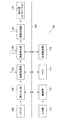
図1は、本発明の一実施形態に係る画像処理装置100の構成例を示す模式図である。画像処理装置100は、例えば比較的小型のディスプレイを備える装置であって、立体映像(3D映像)を表示可能なデバイスである。画像処理装置100に表示する画像としては、静止画、動画のいずれであっても良い。また、画像処理装置100は、表示画面に応じてユーザが画面を操作することによって、各種の入力が可能とされたものである。この画像表示装置100は、デジタルスチルカメラ、デジタルビデオカメラ、パーソナルコンピュータ(PC)、ゲーム機、テレビ受像機、電話、PDA、画像再生装置、画像記録装置、カーナビ、携帯端末、プリンターなどで実現することができる。
[1. Configuration example of image processing apparatus]
FIG. 1 is a schematic diagram illustrating a configuration example of an
なお、3Dの映像方式については特に限定されるものではない。例えば、左目用と右目用の映像を時系列的に交互に表示し、映像の表示と同期してユーザの左右の目に装着した眼鏡シャッターを開閉することにより、左目用と右目用の映像をユーザの左右の目にそれぞれ提供するシステムを用いることができる。また、眼鏡シャッターを用いることなく、偏光板の作用により左右の映像をユーザの左右の目にそれぞれ提供するシステムを用いてもよい。 Note that the 3D video format is not particularly limited. For example, left-eye and right-eye videos are displayed alternately in time series, and the left-eye and right-eye videos are displayed by opening and closing the eyeglass shutters attached to the left and right eyes of the user in synchronization with the video display. A system provided respectively to the left and right eyes of the user can be used. Moreover, you may use the system which each provides a user's left and right eyes with the effect | action of a polarizing plate, without using a spectacles shutter.
図1に示すように、画像処理装置100は、読み出し部102、画像処理部104、視差検出部106、視差制御部108、表示部110、制御部112、メモリ114、近接検出部116を備える。読み出し部102には、メディア200から立体映像を構成する右眼用画像及び左目用画像のデータが送られる。メディア200は、立体映像データを記録した記録媒体であり、一例として、画像処理装置100の外部から装着される。また、入力部118は、表示部110上に設けられたタッチパネルである。画像処理装置100には、入力部118を介してユーザによる操作情報が入力される。入力部118に入力された情報は、制御部112へ送られる。入力部118の操作に基づいて、現在のモードが画像自体を操作する画面(タッチパネル操作が可能な画面)であるか否かを制御部112で判断する。
As illustrated in FIG. 1, the
図1に基づいて、画像処理装置100における基本的な処理を説明すると、先ず、メディア200から画像処理装置100に送られた左右の映像データは、読み出し部102にて読み出され、画像処理部104にて画像処理が行われる。画像処理部104では、左右の画像データの大きさの適正化(リサイズ)、画質調整など、表示用の画像に加工する処理を行う。画像処理部104は、後述するように、視差を調整した結果、視差が両目の幅よりも大きくなる場合等において、画像を縮小する処理を行う。
The basic processing in the
視差検出部106では、左右の画像データを比較し、動きベクトルの検出、ブロックマッチング等の手法により、左右映像の視差を検出する。そして、視差検出部106では、表示面よりも手前に位置する画像があるか否か、視線が交差しない部分があるか否かなどを検出する。
The
視差制御部108は、表示部110のタッチパネル操作が行われる場合に、視差を変更する処理を行う。視差制御部108は、表示面よりも手前に位置する部分や視線が交差する部分がないように視差を調整する。
The
表示部110は、立体映像を表示するディスプレイであり、液晶表示ディスプレイ(LCD)等から構成される。視線調整部108で視差が調整された画像は、表示部110に供給されて表示される。なお、表示部110は、画像処理装置100と一体であっても別体であっても良い。また、表示部110は、入力部118であるタッチパネル(タッチセンサ)を一体に備えている。ユーザは、表示部110に表示された立体映像を視認しながら、タッチパネル操作(入力部118の操作)を行うことができる。なお、表示部110へユーザの指、ペンなどが近接したことを判断する場合は、近接検出部116により近接したことの検出を行い、制御部112で判断を行う。入力部118として、近接を検知可能な静電容量式のタッチセンサ等を用いた場合、近接検出部116は表示部110と同一面にある入力部118と兼用することができる。
The
制御部112は、画像処理装置100の全体を制御する構成要素であって、中央演算処理装置(CPU)等から構成される。メモリ114は、ハードディスク、RAM、ROM等から構成され、左右の映像データを格納する。また、メモリ114は、画像処理装置100を機能させるためのプログラムを格納することができる。近接検出部116は、ユーザによるタッチパネル操作が行われる場合に、ユーザの指、ペン(スタイラス)などが表示部110へ近接したことを検出する。なお、タッチパネルが静電容量を検出する静電容量式のタッチセンサで構成される場合、静電容量の変化により指、ペン等の近接を検出することができるため、近接検出部116はタッチパネルにより構成することができる。
The
図1に示す各構成要素は、バス120によって接続されている。図1に示す各構成要素は、回路(ハードウェア)、または中央演算処理装置(CPU)とこれを機能させるためのプログラム(ソフトウェア)によって構成することができる。
Each component shown in FIG. 1 is connected by a
[2.本実施形態に係る画像処理装置の表示について]
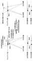
図2は、表示部110に立体映像を表示し、表示部110のタッチパネルをペンで操作した場合の理想的な(自然な)表示状態を示す模式図である。図2(a)は、タッチパネルを操作するペンが表示部110の表示画面上に存在しない場合を示しており、表示部110の左側に3D表示物“A”が表示され、右側に3D表示物“B”が表示されている様子を示している。また、図2(b)は、図2(a)の立体映像を表示している際に、表示部110のタッチパネルをペンで操作している様子を示している。
[2. Regarding display of image processing apparatus according to this embodiment]
FIG. 2 is a schematic diagram illustrating an ideal (natural) display state when a stereoscopic image is displayed on the
図2(a)及び図2(b)の場合、“B”の部分が表示部110の表示面(ディスプレイ面)よりも手前(飛び出して)に表示され、“A”の部分が表示面よりも奥に表示される。図2(b)は、表示面をペンで操作した場合に、本来の位置関係での理想的な見え方を示したもので、表示面を操作しているペンよりも“B”が手前に見えている。従って、ペンは“B”の背後に隠れている。一方、“A”は表示面よりも奥にあるため、“A”はペンの背後に隠れる。図2(C)は、図2(B)の“A”、“B”、ディスプレイ面及びペンの奥行き方向の位置関係を示す図であって、図2(b)を上側から見た状態を示す模式図である。図2(c)に示すように、位置関係としては奥から、“A”、ディスプレイ面、ペン、“B”の順になる。従って、本来の見え方は、図1(B)のようになるのが望ましい。
In the case of FIG. 2A and FIG. 2B, the portion “B” is displayed in front (projected) from the display surface (display surface) of the
図3は、表示部に立体映像を表示し、表示部のタッチパネルをペンで操作した場合に、ユーザに実際に見える見え方を示している。図3(a)及び図3(c)は、図2(a)及び図2(c)とそれぞれ同一である。図3(b)は、3D表示画面上にペンを置いた場合に、ユーザに実際に見える見え方を示している。図3(b)に示すように、本来“B”よりも奥にあるペンが“B”の手前に見えており、ペンが“B”を隠している。ペンが存在しない場合、ユーザには3D表示により“B”が手前に見えているが、実際の光は表示部110のディスプレイ面から発光されており、ディスプレイ面はペンより奥にあるため、このような現象が発生する。この場合、使用者は2つの矛盾する奥行き情報を受け取るため、不自然さを感じ、不快な印象を持つことになる。
FIG. 3 shows how a user can see a 3D image displayed on the display unit and when the touch panel of the display unit is operated with a pen. 3 (a) and 3 (c) are the same as FIGS. 2 (a) and 2 (c), respectively. FIG. 3B shows how the image is actually seen by the user when the pen is placed on the 3D display screen. As shown in FIG. 3B, the pen that is originally behind “B” is visible in front of “B”, and the pen hides “B”. When the pen is not present, the user can see “B” in front by 3D display, but the actual light is emitted from the display surface of the
図4は、図3と同じ位置関係であるが、物体“B”とペンの位置関係について示す模式図である。図4(a)は、使用者からの見え方を示す模式図である。図4(b)及び図4(c)は、奥行き方向の位置関係を示す図であって、図4(a)を左側面から見た状態を示している。図4(b)は、ペンが無い場合の位置関係を示しており、図4(c)は、ペンがある場合の見え方の位置関係を示している。図4(c)に示すように、ペンがある場合は、本来ペンよりも手前に見える筈の“B”の映像が表示面上でペンに遮られてしまうため、表示面よりも手前に見える筈の“B”は、ペンの領域だけ凹んだように見えてしまう。このように、実際の物体を立体視する場合には、物体の位置とその物体が発する光の発生源とは同じ位置であるが、立体画像の場合は、物体の見かけ上の位置と光の発生源の位置とが一致しないため、このような現象が起きてしまい、ユーザは映像の不自然さを感じてしまう。 FIG. 4 is a schematic diagram showing the positional relationship between the object “B” and the pen, which is the same positional relationship as FIG. FIG. 4A is a schematic diagram showing how the user sees it. 4 (b) and 4 (c) are diagrams showing the positional relationship in the depth direction, and show a state when FIG. 4 (a) is viewed from the left side. FIG. 4B shows a positional relationship when there is no pen, and FIG. 4C shows a positional relationship when the pen is visible. As shown in FIG. 4 (c), when there is a pen, the image of “B”, which is originally visible in front of the pen, is obstructed by the pen on the display surface, so that it appears in front of the display surface. The “B” of the eyelid appears to be recessed only in the pen area. In this way, when stereoscopic viewing an actual object, the position of the object and the light source generated by the object are the same position, but in the case of a stereoscopic image, the apparent position of the object and the light source Since the position of the generation source does not match, such a phenomenon occurs, and the user feels unnaturalness of the video.
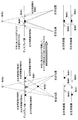
本実施形態では、このような現象を解消するために、ユーザの指やペンが表示面上にある場合は、視差調整を行う。図5は、視差調整の例を示す模式図である。図5の上段の図は、図2(c)と同様に、表示面を上から見たときの奥行き方向の位置を模式的に示している。また、図5の下段の図は、左目用画像と右目用画像のそれぞれにおける物体の表示状態を示している。また、図5の左側の図は視差調整前を示しており、右側の図は視差調整後を示している。 In this embodiment, in order to eliminate such a phenomenon, parallax adjustment is performed when the user's finger or pen is on the display surface. FIG. 5 is a schematic diagram illustrating an example of parallax adjustment. The upper diagram in FIG. 5 schematically shows the position in the depth direction when the display surface is viewed from above, as in FIG. Further, the lower diagram in FIG. 5 shows the display state of the object in each of the left-eye image and the right-eye image. Further, the left diagram in FIG. 5 shows before parallax adjustment, and the right diagram shows after parallax adjustment.
図5の左側の図は視差調整前の状態を示しており、手前と奥に1つずつ物体が見えている(物体C(●)、物体D(○))。これを視差調整して右図のようにして、手前に見える物体Cを表示部110の表示面と同じ位置か、もしくは表示面よりも奥になるようにする。これにより、表示面よりも手前に位置する物体が無くなるため、表示面上にペンを置いた場合であっても、ペンが映像よりも手前に位置するため、映像とペンとの位置関係で不自然さが生じることを回避できる。
The figure on the left side of FIG. 5 shows a state before parallax adjustment, and one object is visible in front and behind (object C (●), object D (◯)). The parallax is adjusted, and the object C seen in the foreground is positioned at the same position as the display surface of the
より詳細に説明すると、図5の上段に示す図は、ユーザと表示部110を上方から見た状態を示しており、ディスプレイ面、ユーザの右目、左目、物体C、物体Dの位置を示している。また、下段に示す図は、表示部110に表示される左目用画像と右目用画像を示している。上段の図に示すように、右目用画像の物体Cと右目を直線で結び、左目用画像の物体Cと左目を直線で結ぶと、2つの直線の交点が物体Cの奥行き方向の位置となる。同様に、右目用画像の物体Dと右目を直線で結び、左目用画像の物体Dと左目を直線で結ぶと、2つの直線の交点が物体Dの奥行き方向の位置となる。なお、物体の奥行き方向の位置は、左目用画像と右目用画像における物体の位置と、右目、左目の位置に基づいて、他の図においても同様に定められる。
More specifically, the diagram shown in the upper part of FIG. 5 shows a state where the user and the
図5の右側の図では、物体Cについて、左目用画像と右目用画像の位置を同一とし、視差を0とすることで、物体Cが表示面上に表示される。また、これに伴い、物体Dについては左目用画像と右目用画像の視差が左側の図よりも大きくなるため、物体Dは表示面に対して左側の図より奥側に表示される。このように、図5に示す例では、物体C、物体Dの表示位置を共に奥側へ移動することで、物体Cは表示面上に表示され、物体Dは表示面に対してより奥の位置に表示される。従って、表示面上にペンが置かれた場合に、ペンよりも物体C、物体Dは奥に表示されるため、ユーザに不自然さや、違和感等が生じてしまうことを抑止できる。なお、物体Cについても、表示面よりも奥の位置に表示するようにしても良い。 In the diagram on the right side of FIG. 5, the object C is displayed on the display surface by setting the left-eye image and the right-eye image at the same position and setting the parallax to 0. As a result, for the object D, the parallax between the left-eye image and the right-eye image is larger than that on the left side, so that the object D is displayed on the far side of the display screen from the left side. As described above, in the example illustrated in FIG. 5, by moving the display positions of the objects C and D to the back side, the object C is displayed on the display surface, and the object D is further on the back of the display surface. Displayed in position. Therefore, when the pen is placed on the display surface, the objects C and D are displayed behind the pen, so that it is possible to prevent the user from feeling unnatural or uncomfortable. Note that the object C may also be displayed at a position behind the display surface.
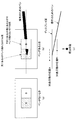
図6は、図5と同様の方法で視差調整を行う場合であるが、ユーザに不自然さを与えてしまう例を示している。図6の左側の図の位置関係に見える画像(物体C、物体D)を視差調整して、図5と同様の方法により物体Cをディスプレイ面に表示し、表示面よりも手前に物体が表示されないようにした場合、右側の図のようになり、両眼の幅よりも広い視差が生じてしまう部分が発生する。 FIG. 6 shows an example in which parallax adjustment is performed in the same manner as in FIG. 5, but gives an unnatural feeling to the user. The images (object C, object D) that appear in the positional relationship in the left diagram of FIG. 6 are adjusted for parallax, and the object C is displayed on the display surface by the same method as in FIG. 5, and the object is displayed in front of the display surface. If it is not performed, a part where the parallax is wider than the width of both eyes is generated as shown in the right figure.
より詳細には、図6の右側の下段の図に示すように、物体Cの視差を0とするために、左目用画像の物体C、物体Dを左方向に移動すると、左目用画像と右目用画像における物体Dの視差が過度に大きくなり、両目の幅よりも大きな視差となってしまう。この場合、物体Dについては、左右の目の視線が交差しないため、ユーザは1つの物体として認識することができず、ユーザの目には物体Dが二重に見えてしまう。 More specifically, as illustrated in the lower diagram on the right side of FIG. 6, when the object C and the object D of the left-eye image are moved leftward in order to set the parallax of the object C to 0, the left-eye image and the right-eye image The parallax of the object D in the image for use becomes excessively large, resulting in a parallax larger than the width of both eyes. In this case, since the line of sight of the left and right eyes does not intersect for the object D, the user cannot recognize it as one object, and the object D appears double to the user's eyes.
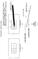
図7は、図6の場合に、奥に見える物体Dの位置は調整せずに、手前に見える物体Cだけを視差調整する場合を示す模式図である。左側の図では、物体Cは手前に見えており、物体Dは奥に見えている。この状態から、右目用画像と左目用画像のそれぞれにおいて、物体Cの位置のみを調整して、物体Cの視差が0となるようにする。具体的には、左側の図に示す左目用画像の物体Cを左方向に移動し、右目用画像の物体Cを右方向に移動する。一方、左目用画像と右目用画像における物体Dの位置は変更しない。これにより、手前に見えていた物体Cは、表示面上に見えるようになる。一方、物体Dは元の視差のままであり、表示面の奥の同じ位置に見えている。このように、手前に見える物体が1つだけであり、そのほかの物体が奥行き方向に離れている場合は、手前に見えている物体のみの位置を調整しても良い。 FIG. 7 is a schematic diagram illustrating a case where the parallax adjustment is performed only on the object C that is visible in the foreground without adjusting the position of the object D that is visible in the back in the case of FIG. 6. In the figure on the left, the object C is visible in the foreground and the object D is visible in the back. From this state, only the position of the object C is adjusted in each of the right-eye image and the left-eye image so that the parallax of the object C becomes zero. Specifically, the object C of the left-eye image shown in the left figure is moved in the left direction, and the object C of the right-eye image is moved in the right direction. On the other hand, the position of the object D in the left-eye image and the right-eye image is not changed. As a result, the object C that was visible in the foreground becomes visible on the display surface. On the other hand, the object D remains in the original parallax and is seen at the same position in the back of the display surface. In this way, when only one object is visible in the foreground and other objects are separated in the depth direction, the position of only the object that is visible in the foreground may be adjusted.
図8は、手前に複数の物体が見えている場合を示している。図8の左側の図では、物体Cと物体Eが表示面よりも手前に見えており、物体Dが表示面よりも奥に見えている場合を示している。この場合、手前に見えている物体Cと物体Eのみの視差を調整して、物体Cと物体Eがディスプレイ面上に見えるようにすることで、ユーザの指やペンなどがディスプレイ面上に位置した場合にユーザに違和感が生じてしまうことを回避できる。ここで、全ての物体の視差を一律に調整することなく、手前に見えている物体の視差のみを調整することを、「視差変更」と称することとする。一方、図6などで既に説明した全ての物体の視差を調整することを、「視差調整」と称することとする。図8のような視差変更を行った場合、元々ディスプレイ面よりも手前の異なる奥行き位置に見えていた物体Cと物体Eがともにディスプレイ面上に位置するため、物体Cと物体Eの相互の奥行き感がなくなってしまう。 FIG. 8 shows a case where a plurality of objects are visible in front. The left diagram in FIG. 8 shows a case where the object C and the object E are seen in front of the display surface and the object D is seen in the back of the display surface. In this case, by adjusting the parallax between the object C and the object E that are visible in the foreground so that the object C and the object E can be seen on the display surface, the user's finger or pen is positioned on the display surface. In this case, it can be avoided that the user feels uncomfortable. Here, adjusting only the parallax of an object that is seen in the foreground without uniformly adjusting the parallax of all objects is referred to as “parallax change”. On the other hand, adjusting the parallax of all the objects already described in FIG. 6 and the like is referred to as “parallax adjustment”. When the parallax change as shown in FIG. 8 is performed, the object C and the object E that were originally seen at different depth positions in front of the display surface are both positioned on the display surface, and thus the mutual depth between the object C and the object E The feeling disappears.
図9は、全ての物体をディスプレイ面上に表示して2次元画像を表示する場合を示している。図6で説明したように、ディスプレイ面よりも手前に物体を表示しないように視差調整した際に、両眼の幅より視差が大きくなってしまう部分が発生する場合は、視差調整を行い、2次元で映像を表示するようにする。図9の例では、物体C、物体D、物体Eのそれぞれの視差を0とすることで、物体C、物体D及び物体Eを2次元で表示している。この場合、図9の下段に示すように、物体C、物体D及び物体Eのそれぞれについて、左目用画像と右目用画像の位置を調整して視差を0にする。 FIG. 9 shows a case where a two-dimensional image is displayed by displaying all objects on the display surface. As described with reference to FIG. 6, when a portion where the parallax is larger than the width of both eyes occurs when the parallax adjustment is performed so that the object is not displayed in front of the display surface, the parallax adjustment is performed. Display images in dimensions. In the example of FIG. 9, the object C, the object D, and the object E are displayed in two dimensions by setting the parallaxes of the object C, the object D, and the object E to 0. In this case, as shown in the lower part of FIG. 9, for each of the object C, the object D, and the object E, the positions of the left-eye image and the right-eye image are adjusted to make the parallax zero.
図10は、2次元表示する場合に、1つの視点の画像を使って表示する例を示す模式図である。図10に示す例では、右側の図の下段に示すように、右目用画像として左目用画像と同一の画像を表示する。これにより、特に右目用画像と左目用画像の視差を調整することなく、2次元表示を行うことが可能である。従って、ブロックマッチング等により視差を検出する処理を行う必要がなく、図9の場合と比較すると、より簡素な処理で2次元画像を表示することが可能である。 FIG. 10 is a schematic diagram illustrating an example in which an image from one viewpoint is used for two-dimensional display. In the example shown in FIG. 10, the same image as the left-eye image is displayed as the right-eye image, as shown in the lower part of the right diagram. As a result, two-dimensional display can be performed without particularly adjusting the parallax between the right-eye image and the left-eye image. Therefore, it is not necessary to perform a process of detecting parallax by block matching or the like, and it is possible to display a two-dimensional image with a simpler process compared to the case of FIG.
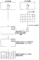
図11及び図12は、図6で説明したように、視差を調整した結果、視差が両眼の幅よりも広くなってしまう場合に、画像の縮小を行う例を示している。図11の右側は、左側に対して左右の画像をともに縮小した場合を示している。図11に示すように、画像の大きさは一定値以下となると、視線が交差しない画像を作成することができない。従って、図6の右側の図で説明したような、両眼の幅よりも広い視差が生じてしまう部分は発生しない。 11 and 12 illustrate an example in which the image is reduced when the parallax becomes wider than the width of both eyes as a result of adjusting the parallax as described in FIG. 6. The right side of FIG. 11 shows a case where the left and right images are both reduced with respect to the left side. As shown in FIG. 11, when the size of the image is a certain value or less, it is impossible to create an image in which the line of sight does not intersect. Accordingly, a portion where a parallax wider than the width of both eyes is generated as described in the diagram on the right side of FIG. 6 does not occur.
図12の左側の図は、図6の右側の図に対応しており、両眼の幅よりも広い視差が生じてしまう部分が発生した状態を示している。図12の右側の図は、図11の原理を用いて、図12の左側の図を縮小した状態を示している。図12の左側の図(図6の右側の図)に示すように、視差を調整した結果、両眼の幅よりも視差が大きくなると、3D画像を表示することはできないため、図12の右側の図に示すように、左右の画像を縮小して視差を両目の幅よりも狭くする。これにより、手前に表示されていた部分をディスプレイ面上に表示できるとともに、図6の右側の図のように視差が両眼の幅よりも大きくなってしまうことを回避できる。従って、縮小を行うことで、視差を両眼の幅よりも狭くすることができ、物体が二重に見えてしまうことを回避できる。 The left diagram in FIG. 12 corresponds to the diagram on the right in FIG. 6 and shows a state in which a portion where parallax wider than the width of both eyes is generated has occurred. The diagram on the right side of FIG. 12 shows a state in which the diagram on the left side of FIG. 12 is reduced using the principle of FIG. As shown in the diagram on the left side of FIG. 12 (the diagram on the right side of FIG. 6), as a result of adjusting the parallax, if the parallax becomes larger than the width of both eyes, a 3D image cannot be displayed. As shown in the figure, the left and right images are reduced to make the parallax narrower than the width of both eyes. As a result, the portion displayed in the foreground can be displayed on the display surface, and the parallax can be prevented from becoming larger than the width of both eyes as shown in the diagram on the right side of FIG. Therefore, by performing the reduction, the parallax can be made narrower than the width of both eyes, and it can be avoided that the object looks double.
図13は、視差調整のための、視差量の検出方法の例を示す模式図である。視差を求める2つの画像(左目用画像と右目用画像)の一方をブロックに分割して、各ブロックを他方の画像と比較した場合に、各ブロックが他方の画像のどの部分との間で誤差が最小になるかを求める。そして、他方の画像上での誤差が最小となる位置と、もともとのブロックの位置の差が視差量となる。図13に示すように、視差量は、ブロック毎にベクトル値として求められる。図13の例では、右目用画像をブロックに分割して、各ブロックを左目用画像と比較し、左目用画像と各ブロックとの間で誤差が最小になる位置を探索する。そして、誤差が最小となる位置とブロック抽出時の位置との差を動きベクトルとして、画面全体の各ブロックについての動きベクトルを算出する。 FIG. 13 is a schematic diagram illustrating an example of a parallax amount detection method for parallax adjustment. When one of two images (left-eye image and right-eye image) for which parallax is calculated is divided into blocks and each block is compared with the other image, each block has an error with which part of the other image. Finds if is minimal. The difference between the position where the error on the other image is minimum and the position of the original block is the amount of parallax. As shown in FIG. 13, the parallax amount is obtained as a vector value for each block. In the example of FIG. 13, the right-eye image is divided into blocks, each block is compared with the left-eye image, and a position where the error is minimized between the left-eye image and each block is searched. Then, the motion vector for each block of the entire screen is calculated using the difference between the position where the error is minimum and the position at the time of block extraction as the motion vector.
図13に示す例では、右目用画像のブロックに対して、左目用画像の対応する位置が左側にずれている場合は、動きベクトルは右から左へ向かうベクトルとなる。図5の左側の図等に示すように、右目用画像のブロックに対して左目用画像の対応する位置が左側にずれている場合は、表示面よりも奥に物体が表示される(図5の左側の図に示す物体D)。一方、右目用画像のブロックに対して左目用画像の対応する位置が右側にずれている場合は、表示面よりも手前に物体が表示される(図5の左側の図に示す物体C)。従って、図13に示すように、各ブロックの動きベクトルを算出した場合に、動きベクトルが右から左へ向かうベクトルの場合は、そのブロックに対応する物体が表示面の奥に表示され、動きベクトルが左から右へ向かうベクトルの場合は、そのブロックに対応する物体が表示面の手前に表示されることが判る。また、動きベクトルが右から左へ向かうベクトルの場合、ベクトルの絶対値が大きいほど、そのブロックに対応する物体が表示面のより奥に表示される。動きベクトルが左から右へ向かうベクトルの場合、ベクトルの絶対値が大きいほど、そのブロックに対応する物体が表示面のより手前に表示される。なお、図13に示す処理は、図1に示す視差検出部106で行われる。
In the example illustrated in FIG. 13, when the corresponding position of the left-eye image is shifted to the left with respect to the block of the right-eye image, the motion vector is a vector from right to left. As shown in the left diagram of FIG. 5 and the like, when the corresponding position of the left-eye image is shifted to the left with respect to the block of the right-eye image, the object is displayed behind the display surface (FIG. 5). Object D) shown on the left side of FIG. On the other hand, when the corresponding position of the left-eye image is shifted to the right with respect to the block of the right-eye image, an object is displayed in front of the display surface (object C shown in the left diagram of FIG. 5). Therefore, as shown in FIG. 13, when the motion vector of each block is calculated, if the motion vector is a vector from right to left, the object corresponding to the block is displayed at the back of the display surface, and the motion vector When is a vector from left to right, it can be seen that an object corresponding to the block is displayed in front of the display surface. When the motion vector is a vector from right to left, the larger the absolute value of the vector is, the deeper the object corresponding to the block is displayed. When the motion vector is a vector from left to right, the larger the absolute value of the vector, the more the object corresponding to the block is displayed in front of the display surface. Note that the processing shown in FIG. 13 is performed by the
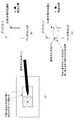
視差を調整する際には、動きベクトルが左から右へ向かうベクトルのブロックの中から、その絶対値(=A)が最大のブロック(ここでは、ブロック1とする)を抽出する。この抽出されたブロック1の画像は、最も手前に位置するので、このブロックの動きベクトルの大きさを“0”に調整する。そして、他のブロックについては、各ブロックの動きベクトルからブロック1の動きベクトルだけ減算する処理を行う。これにより、図6で説明したように、全ての物体の奥行き方向の位置を一律に奥側へ移動することができる。なお、図8で説明したような視差変更を行う場合は、動きベクトルが左から右へ向かう全てのブロックの動きベクトルの大きさを“0”に調整する。なお、このような視差の調整は、図1に示す視差制御部108で行われる。
When adjusting the parallax, a block having a maximum absolute value (= A) (here, referred to as block 1) is extracted from a block of vectors whose motion vectors are from left to right. Since the extracted image of
図14は、表示部110の表示画面111に表示される画像にタッチパネル操作用の操作枠112をつけた例を示す模式図である。ここで、操作枠112は2次元画像で表示する。操作枠112を画像の外側に設けることで、ペンが操作枠112を操作した場合に、3D表示が行われている画像の表示領域と重なることがないため、3D表示されている画像とペンが重なることによる不自然さ、違和感を抑止できる。ここで、図14の上段は、表示画面1111内に複数の画像をサムネイルの状態で表示し、各画像の周囲に操作枠112を設けた例を示している。また、図14の下段は、表示画面111内に1の画像を表示し、1の画像の周囲に操作枠112を設けた例を示している。
FIG. 14 is a schematic diagram illustrating an example in which an
図15は、図14の表示部110を縦に配置した例を示す模式図である。図15の例においても、タッチパネル操作の際に指やペンが3Dの画像に直接触れることがないため、不快感を無くすことが可能である。
FIG. 15 is a schematic diagram illustrating an example in which the
図16は、ペンがディスプレイ面に近接したことを検知する近接検知センサーを、タッチパネルで兼用する例を示す模式図である。例えば、静電容量式のタッチパネルを用いた場合、近接検知センサー(近接検出部116)をタッチパネルで兼用することが可能である。 FIG. 16 is a schematic diagram illustrating an example in which a proximity detection sensor that detects that a pen has approached the display surface is also used as a touch panel. For example, when a capacitive touch panel is used, the proximity detection sensor (proximity detection unit 116) can also be used as a touch panel.
図16の上段の図は、ディスプレイ面と平行な方向から見た状態を示しており、ディスプレイ面にペンが接近または接触した場合を示している。また、図16の中段の図は、ディスプレイ面の上側から状態を示しており、ディスプレイ面にペンが接近または接触した場合を示している。また、図16の下段の図は、ディスプレイ面にペンが接近または接触した場合に、タッチセンサで検出される静電容量の変化を示しており、ドットを付した領域の静電容量が高くなった状態を示している。 The upper part of FIG. 16 shows a state viewed from a direction parallel to the display surface, and shows a case where the pen approaches or contacts the display surface. The middle diagram of FIG. 16 shows a state from the upper side of the display surface, and shows a case where the pen approaches or contacts the display surface. The lower diagram of FIG. 16 shows the change in capacitance detected by the touch sensor when the pen approaches or comes into contact with the display surface, and the capacitance in the region marked with dots increases. Shows the state.
図16の下段の図に示すように、ペンが近づいてくる過程では、ペンと近接している場所の静電容量が変化し、ペンが表示画面に接触すると静電容量の変化がより大きくなる。従って、これを用いてペンがどの程度近接しているか、あるいは接触しているかを判断することができる。 As shown in the lower diagram of FIG. 16, in the process of approaching the pen, the capacitance at a location close to the pen changes, and the capacitance changes more when the pen touches the display screen. . Therefore, it can be used to determine how close or in contact the pen is.
[3.本実施形態の画像処理装置における処理について]
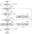
次に、本実施形態の画像処理装置100による処理について説明する。なお、以下に示す各処理は、制御部112の制御によって図1の各構成要素の機能を制御することによって実現することができる。図17は、画像操作時の動作を示すフローチャートである。先ず、ステップS101では、画像を読み出し、ステップS102で画像を操作可能な画面であるか否か判断する。すなわち、ステップS102では、タッチパネル操作により画面を操作できるモードであるか否かを判断する。この場合に、近接検出部116によりユーザの指またはペン等が表示面に近づいたことが検知された場合に、タッチパネル操作により画面を操作できるモードであると判断することができる。ステップS102において、操作可能な画面でない場合は、ステップS106へ進み、画面をそのまま表示する。
[3. Regarding processing in the image processing apparatus of the present embodiment]
Next, processing by the
一方、タッチパネルによる操作が可能な画面の場合は、ステップS103へ進み、表示面より手前になる部分があるか否かを判断する。モードの切り換えの設定がユーザの操作によって行われる場合、タッチパネル操作が可能な画面に設定されたときはステップS102からステップS103へ進み、タッチパネル操作ができない画面に設定されたときはステップS102からステップS106へ進む。 On the other hand, in the case of a screen that can be operated with the touch panel, the process proceeds to step S103, and it is determined whether or not there is a portion in front of the display surface. When the mode switching setting is performed by the user's operation, the process proceeds from step S102 to step S103 when a screen capable of touch panel operation is set, and from step S102 to step S106 when the screen is set such that the touch panel operation is not possible. Proceed to
ステップS103では、3D表示により表示面よりも手前に表示されている物があるか否かを判断する。そして、表示面よりも手前に表示される部分が存在しない場合は、ステップS106へ進み、画像をそのまま表示する。一方、表示面よりも手前に表示される物が存在する場合は、ステップS104へ進み、視差調整した場合に正しい表示になるか否かを判断する。すなわち、ステップS104では、視差調整をした場合に、図6の右側の図に示したように、両眼の幅より視差が大きくなる部分があるか否かを判断し、正しい表示になる場合、つまり、両目の幅よりも視差が大きくなる部分が無い場合は、ステップS105へ進む。ステップS105では、表示面よりも手前に位置する部分が表示面上に表示されるように視差調整を行う。これにより、ステップS106では、表示面よりも手前にある部分をなくした状態で画像が表示される。一方、ステップS104で正しい表示にならないと判断された場合は、ステップS107へ進み、視差変更を行うか、または、図10で説明したように、片側の視点の画像のみを用いて二次元表示を行う。ここで、視差変更とは、図7で説明したように、手前に見える部分のみを表示面上に移動する処理をいう。これにより、表示面よりも手前になる部分を無くした状態で3D画像を表示することができる。 In step S103, it is determined whether or not there is an object displayed in front of the display surface by 3D display. If there is no portion displayed in front of the display surface, the process proceeds to step S106, and the image is displayed as it is. On the other hand, when there is an object displayed in front of the display surface, the process proceeds to step S104, and it is determined whether or not the display is correct when the parallax is adjusted. That is, in step S104, when parallax adjustment is performed, it is determined whether there is a part where the parallax is larger than the width of both eyes, as shown in the diagram on the right side of FIG. That is, if there is no portion where the parallax is larger than the width of both eyes, the process proceeds to step S105. In step S105, parallax adjustment is performed so that a portion positioned in front of the display surface is displayed on the display surface. As a result, in step S106, the image is displayed in a state where the portion in front of the display surface is eliminated. On the other hand, if it is determined in step S104 that the display is not correct, the process proceeds to step S107, where the parallax is changed or, as described with reference to FIG. 10, the two-dimensional display is performed using only one viewpoint image. Do. Here, the parallax change refers to a process of moving only the portion that is visible in the foreground onto the display surface, as described with reference to FIG. As a result, the 3D image can be displayed in a state where the portion in front of the display surface is eliminated.
図18は、タッチパネルを操作して画像を拡大する際の処理を示すフローチャートである。画像の拡大が行われると、拡大に伴って左右の画像の視差が大きくなり、視差が両目の幅よりも大きくなると、図6で説明したように物が二重に見えてしまう事態が発生する。このため、図18の処理では、拡大操作が行われるたびに、正しい表示が行われるか否かを判定し(ステップS204)、正しい表示にならない場合は2次元画像で表示を行う。これにより、拡大操作が行われる場合に、正常な表示を維持するとともに、ユーザの指やペンが表示面の手間に表示される画像と重ならないようにすることができる。 FIG. 18 is a flowchart illustrating processing when an image is enlarged by operating the touch panel. When the image is enlarged, the parallax between the left and right images increases with the enlargement, and when the parallax becomes larger than the width of both eyes, a situation occurs in which objects appear double as described with reference to FIG. . For this reason, in the process of FIG. 18, each time an enlargement operation is performed, it is determined whether or not correct display is performed (step S204). If the display is not correct, display is performed with a two-dimensional image. Accordingly, when an enlargement operation is performed, it is possible to maintain normal display and prevent the user's finger or pen from overlapping the image displayed on the display surface.
図17では、ステップS102で画像自体を操作する画面であるか否かを判定したが、図18のステップS202では、ステップS102の代わりに、画像の拡大操作が行われたか否かを判定する。画像の拡大操作が行われた場合は、ステップS203へ進み、拡大する画像に表示される物体が表示面よりも手前になるか否かを判定する。一方、画像の拡大操作が行われない場合は、ステップS206へ進む。ステップS203〜S207の処理は、図16のステップS103〜S107と同様である。そして、ステップS202からステップS206へ進んだ場合は、ステップS206にて拡大した画像を表示する。これにより、拡大された画像内で表示面よりも手前の位置に物体が表示されてしまうことを回避できる。 In FIG. 17, it is determined whether or not the screen is for operating the image itself in step S <b> 102, but in step S <b> 202 of FIG. 18, it is determined whether or not an image enlargement operation is performed instead of step S <b> 102. If an image enlargement operation has been performed, the process proceeds to step S203, and it is determined whether or not the object displayed in the image to be enlarged is in front of the display surface. On the other hand, if the image enlargement operation is not performed, the process proceeds to step S206. The processing in steps S203 to S207 is the same as that in steps S103 to S107 in FIG. If the process proceeds from step S202 to step S206, the image enlarged in step S206 is displayed. Thereby, it can be avoided that an object is displayed at a position in front of the display surface in the enlarged image.
また、画像の拡大率が大きく、ステップS204において、視差調整しても正しい表示にならない場合は、ステップS207へ進み、視差変更もしくは2Dによる表示を行う。従って、拡大が行われる毎に正しい表示になるか否かがステップS204で判断され、正しい表示ができない場合は視差変更もしくは2Dによる表示を行うことで、ユーザが不自然さを感じてしまうことを抑止できる。なお、視差変更を行う場合は、上述したように、表示面の手前に位置する物体の視差のみを変更するため、表示面よりも奥に位置する物体の視差は変更されない。従って、図6の右側の図に示したような、物体が2重に見えてしまう事態を回避することが可能である。 If the image enlargement ratio is large and the display is not correct even after adjusting the parallax in step S204, the process proceeds to step S207, where the parallax change or 2D display is performed. Therefore, it is determined in step S204 whether or not a correct display is obtained each time enlargement is performed. If correct display is not possible, the parallax change or 2D display is performed, and the user feels unnatural. Can be suppressed. Note that when changing the parallax, as described above, since only the parallax of the object located in front of the display surface is changed, the parallax of the object located behind the display surface is not changed. Therefore, it is possible to avoid a situation in which an object looks double as shown in the diagram on the right side of FIG.
また、図18では、ステップS206の後、ステップS208へ進み、画像の拡大・縮小操作が行われたか否かを更に判断する。そして、画像の拡大・縮小操作が行われた場合は、ステップS209へ進み、画像の拡大・縮小を行う。ステップS209の後はステップS203以降の処理へ戻り、拡大・縮小が行われた後の画像について、表示面よりも手前に位置する画像があるか否かを判断する。 In FIG. 18, after step S206, the process proceeds to step S208 to further determine whether or not an image enlargement / reduction operation has been performed. If an image enlargement / reduction operation has been performed, the process advances to step S209 to enlarge / reduce the image. After step S209, the process returns to step S203 and the subsequent steps, and it is determined whether or not there is an image positioned before the display surface with respect to the image after the enlargement / reduction.
また、ステップS207の後はステップS211へ進み、画像の拡大・縮小操作が行われたか否かを判定する。そして、画像の拡大・縮小操作が行われた場合は、ステップS212へ進み、画像の拡大・縮小操作を行い、ステップS210で拡大・縮小後の画像を表示する。 After step S207, the process proceeds to step S211 to determine whether an image enlargement / reduction operation has been performed. If an image enlargement / reduction operation has been performed, the process proceeds to step S212, the image enlargement / reduction operation is performed, and the image after enlargement / reduction is displayed in step S210.
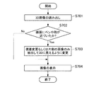
以上のように、図18の処理によれば、画像を拡大して3D表示ができなくなると、2D表示を行うことができる。従って、画像の拡大によって図6の右側の図に示すように3D表示ができなくなる場合は、2D表示に切り換えることができるため、拡大に起因して3D表示ができなくなることを回避できる。 As described above, according to the processing in FIG. 18, when the image is enlarged and 3D display cannot be performed, 2D display can be performed. Accordingly, when the 3D display cannot be performed due to the enlargement of the image as shown in the right side of FIG. 6, the display can be switched to the 2D display, so that the 3D display cannot be prevented due to the enlargement.
図19は、図18の処理を行った場合に、拡大して3D表示ができなくなると、拡大できない旨の表示をして拡大率を制限する処理を示している。図19では、図18に対して、ステップS204で“NO”判定がされた場合の処理が異なっている。ステップS204において、視差調整した場合に正しい表示にならないことが判定されると、ステップS213へ進む。ステップS213では、直前の拡大前の画像に戻す処理を行う。ステップS213の後はステップS214へ進み、拡大できない旨の表示を行う。これにより、ユーザは、更なる拡大ができないことを認識することができる。 FIG. 19 shows a process of limiting the enlargement ratio by displaying that the image cannot be enlarged when the process of FIG. 19 differs from FIG. 18 in the case where “NO” determination is made in step S204. If it is determined in step S204 that the display is not correct when the parallax is adjusted, the process proceeds to step S213. In step S213, processing for returning to the immediately previous image before enlargement is performed. After step S213, the process proceeds to step S214 to display that the image cannot be enlarged. Thereby, the user can recognize that further enlargement cannot be performed.
図20は、正しい表示ができない場合に、図17で説明した視差変更または二次元表示を行う代わりに、視差調整を行い手前に表示される部分をなくした上で、すべての部分の視差が両眼の幅より小さくなるように縮小し表示を行う処理を示すフローチャートである。この処理は、図12の表示処理に対応する。図20の処理は、ステップS307以外の処理は図17と同様であり、図20のステップS301〜S306は図17のステップS101〜S106に対応する。ステップS304で、視差調整をした場合に正しい表示にならないと判断された場合、ステップS307へ進む。ステップS307では、視差調整をして表示面よりも手前になる部分をなくし、更に、図12で説明したように、視差が交差しない部分がなくなるまで画像の表示部分を縮小する。そして、次のステップS306では、縮小した画像を表示する。この処理によれば、画像は縮小されるものの、多視点表示(立体映像表示)を維持することができる。 FIG. 20 shows that when correct display is not possible, instead of performing the parallax change or two-dimensional display described in FIG. It is a flowchart which shows the process which reduces and displays so that it may become smaller than the width | variety of an eye. This process corresponds to the display process of FIG. The processes in FIG. 20 are the same as those in FIG. 17 except for step S307, and steps S301 to S306 in FIG. 20 correspond to steps S101 to S106 in FIG. If it is determined in step S304 that the display is not correct when the parallax adjustment is performed, the process proceeds to step S307. In step S307, the parallax adjustment is performed to eliminate the portion that is in front of the display surface, and further, as described in FIG. 12, the display portion of the image is reduced until there is no portion where the parallax does not intersect. In the next step S306, the reduced image is displayed. According to this processing, although the image is reduced, multi-view display (stereoscopic image display) can be maintained.
図21は、図17と図20の場合を切り替えて行う処理を示すフローチャートである。ここでは、視差調整した場合に正しい表示にならない場合は、ステップS404に進み、表示サイズと3D表示のいずれが重要かを判断する。そして、3D表示の方が重要な場合は、ステップS405へ進み、視差調整を行うとともに、視線が交差しない部分がなくなる大きさへ縮小して表示を行う。つまり、この場合は図20のステップS307の処理を行う。これにより、画面のサイズは小さくなるが、3D表示を行うことができる。 FIG. 21 is a flowchart showing processing performed by switching between the cases of FIGS. 17 and 20. Here, when the display is not correct when the parallax is adjusted, the process proceeds to step S404, and it is determined which of the display size and the 3D display is important. If 3D display is more important, the process proceeds to step S405, where parallax adjustment is performed and the display is reduced to a size that eliminates the portion where the line of sight does not intersect. That is, in this case, the process of step S307 in FIG. 20 is performed. Thereby, although the size of the screen is reduced, 3D display can be performed.
また、ステップS404において、3D表示よりも表示サイズの方が重要な場合は、ステップS408へ進み、視差を変更するか、もしくは片側の画像のみを抽出して2Dでの表示を行う。つまり、この場合は、図17のステップS107の処理を行う。このように、図21の処理によれば、3Dなどの多視点表示と、画像の大きさのどちらが重要か判断して、視差調整して縮小表示するか、2次元(または視差変更)で表示するかを決定する。この判断は使用者が入力部で設定してもよいし、画像処理装置100側で表示の状態に応じて判断してもよい。
If the display size is more important than the 3D display in step S404, the process proceeds to step S408, where the parallax is changed, or only one image is extracted and displayed in 2D. That is, in this case, the process of step S107 in FIG. 17 is performed. As described above, according to the processing of FIG. 21, it is determined which of 3D or other multi-viewpoint display is important and the size of the image is important, and parallax adjustment is performed for reduced display, or two-dimensional (or parallax change) display is performed. Decide what to do. This determination may be set by the user using the input unit, or may be determined according to the display state on the
図22は、画像の横幅が両眼の幅より小さい場合を示すフローチャートである。人間の両目の幅は、通常、5cm〜7cm程度であるため、図22は、画像の横幅が5cm〜7cm程度以下の場合に該当する。この場合は、画像の幅が狭く、図6の右側の図に示したような状況が発生することがないため、視差調整により手前に表示する部分を表示面に移動するのみでよく、視差調整が可能である。換言すれば、図6の右側の図に示したような状況は発生しないため、図17のステップS104の処理が不要となる。その他の処理は、図17と同様である。なお、この場合、視差が交差しない部分は画像の横幅の外になるため、表示されることがない。 FIG. 22 is a flowchart illustrating a case where the horizontal width of the image is smaller than the width of both eyes. Since the width of both human eyes is usually about 5 cm to 7 cm, FIG. 22 corresponds to the case where the horizontal width of the image is about 5 cm to 7 cm or less. In this case, since the width of the image is narrow and the situation as shown in the right side of FIG. 6 does not occur, it is only necessary to move the portion displayed in front by parallax adjustment to the display surface. Is possible. In other words, the situation shown in the diagram on the right side of FIG. 6 does not occur, and therefore the processing in step S104 in FIG. 17 is not necessary. Other processes are the same as those in FIG. In this case, the part where the parallax does not intersect is outside the horizontal width of the image, and thus is not displayed.
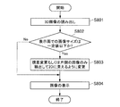
図23は、タッチパネル等により画面を操作する表示となった場合に、視差変更を行うか、または2次元表示に切り換える処理を示すフローチャートである。ステップS602において、画面自体を操作する画面であることが判定されると、ステップS603へ進み、視差変更を行うか、または片側の画像のみを抽出して2次元での表示を行う。これにより、表示面よりも手前に表示される物体がなくなるため、タッチパネル操作の際にユーザに違和感が生じてしまうことを抑止できる。 FIG. 23 is a flowchart showing a process of changing the parallax or switching to a two-dimensional display when the display is operated by operating the touch panel or the like. If it is determined in step S602 that the screen itself is an operation screen, the process proceeds to step S603, where the parallax is changed, or only one image is extracted and displayed in two dimensions. Thereby, since there is no object displayed in front of the display surface, it is possible to prevent the user from feeling uncomfortable during the touch panel operation.
図24は、タッチパネル等による画面の操作が予想される場合に、視差変更を行うか、または2次元表示に切り換える処理を示すフローチャートである。ステップS702において、画面にペンや指が近づいたことが検出されると、ステップS703へ進み、視差変更を行うか、または片側の画像のみを抽出して2次元表示を行う。このように、実際に画面操作が行われていない場合においても、ユーザの指やペンなどの近接に応じて、画面の操作が予想される場合に視差変更または2次元での表示を行う。なお、上述したように、ペン、又は指などが近接したことは、近接検出部116や、静電容量式のタッチパネルにより検出する。
FIG. 24 is a flowchart illustrating processing for changing parallax or switching to two-dimensional display when a screen operation using a touch panel or the like is expected. In step S702, when it is detected that a pen or a finger has approached the screen, the process proceeds to step S703, where the parallax is changed, or only one image is extracted and two-dimensional display is performed. Thus, even when the screen operation is not actually performed, the parallax change or the two-dimensional display is performed when the screen operation is expected according to the proximity of the user's finger or pen. Note that as described above, the proximity of the pen or the finger is detected by the
図25は、タッチパネル操作が可能な表示の場合に、画像が所定のサイズよりも小さい場合は、視差変更もしくは2次元表示にする処理を示すフローチャートである。このように、例えばサムネイルなどの小さい画像の場合は立体感が弱くなり易いため、所定のサイズよりも小さい画像を表示することを条件として、視差変更または2次元表示にすることもできる。 FIG. 25 is a flowchart illustrating processing for changing parallax or performing two-dimensional display when an image is smaller than a predetermined size in the case of display capable of touch panel operation. As described above, for example, in the case of a small image such as a thumbnail, the stereoscopic effect tends to be weak, and therefore, parallax change or two-dimensional display can be performed on condition that an image smaller than a predetermined size is displayed.
図26は、図14及び図15で説明したような操作枠112を設けた場合の処理を示すフローチャートである。ステップS902において、タッチパネルなどで画面自体を操作する画面であると判定された場合は、ステップS903にて画像と関連付けた2次元の操作枠112を表示する。これにより、ユーザは指やペンで操作枠112を操作し、3次元の画像上に指またはペンが位置することがないため、3D画像と指やペンなどが重なることにより違和感の発生を抑止できる。
FIG. 26 is a flowchart showing processing when the
以上説明したように本実施形態によれば、手前に表示されるものがなくなるので、画像の中に指やペンと不自然な関係をもつ部分を無くすことができ、使用者に不快感を与えてしまうことを抑止できる。また、両眼の幅より広い視差を有する画像が表示されることがないため、同一物体が二重に見えてしまうことを抑止でき、使用者が違和感を感じることを確実に抑えることが可能となる。 As described above, according to the present embodiment, since there is nothing to be displayed in the foreground, it is possible to eliminate a portion having an unnatural relationship with a finger or a pen in the image, and to give the user an uncomfortable feeling. Can be prevented. In addition, since an image having a parallax wider than the width of both eyes is not displayed, it is possible to prevent the same object from appearing double, and to reliably prevent the user from feeling uncomfortable. Become.
以上、添付図面を参照しながら本発明の好適な実施形態について詳細に説明したが、本発明はかかる例に限定されない。本発明の属する技術の分野における通常の知識を有する者であれば、特許請求の範囲に記載された技術的思想の範疇内において、各種の変更例または修正例に想到し得ることは明らかであり、これらについても、当然に本発明の技術的範囲に属するものと了解される。 The preferred embodiments of the present invention have been described in detail above with reference to the accompanying drawings, but the present invention is not limited to such examples. It is obvious that a person having ordinary knowledge in the technical field to which the present invention pertains can come up with various changes or modifications within the scope of the technical idea described in the claims. Of course, it is understood that these also belong to the technical scope of the present invention.
100 画像処理装置
104 画像処理部
106 視差検出部
108 視差制御部
110 表示部
116 近接検出部
118 入力部
DESCRIPTION OF
Claims (17)
前記複数視点画像を構成する各画像の視差を検出する視差検出部と、
少なくとも前記入力部により前記表示画像上での操作を行うことができる場合に、前記複数視点画像の視差を調整する視差制御部と、
を備える、画像処理装置。 An input unit capable of performing operation input on a display image by a plurality of viewpoint images;
A parallax detection unit for detecting parallax of each image constituting the multi-viewpoint image;
A parallax control unit that adjusts the parallax of the multi-viewpoint image when at least the operation on the display image can be performed by the input unit;
An image processing apparatus comprising:
前記視差制御部は、前記近接検出部により操作者の指又は操作物が近接したことが検出された場合に、前記複数視点画像の視差を調整する、請求項1に記載の画像処理装置。 A proximity detection unit that detects that an operator's finger or operation object has approached the display surface that emits the light of the display image;
The image processing apparatus according to claim 1, wherein the parallax control unit adjusts parallax of the multi-viewpoint image when the proximity detection unit detects that an operator's finger or an operation object is approaching.
前記近接検出部は、前記タッチセンサから構成され、静電容量の変化に基づいて前記操作者の指又は操作物が近接したことを検出する、請求項8に記載の画像処理装置。 The input unit includes a capacitive touch sensor provided on the display surface,
The image processing apparatus according to claim 8, wherein the proximity detection unit is configured by the touch sensor, and detects that the operator's finger or operation object has approached based on a change in capacitance.
前記視差検出部により正常な表示ができないと判定された場合に、前記表示画像を縮小する画像処理部を備える、請求項1に記載の画像処理装置。 The parallax detection unit determines whether normal display is possible as a result of parallax adjustment by the parallax control unit;
The image processing apparatus according to claim 1, further comprising: an image processing unit that reduces the display image when the parallax detection unit determines that normal display cannot be performed.
前記視差検出部により正常な表示ができないと判定された場合に、前記表示画像を縮小する画像処理部を備える、請求項12に記載の画像処理装置。 The parallax detection unit determines whether normal display is possible as a result of parallax adjustment by the parallax control unit;
The image processing apparatus according to claim 12, further comprising an image processing unit that reduces the display image when the parallax detection unit determines that normal display cannot be performed.
前記複数視点画像を構成する各画像の視差を検出する視差検出部と、
前記表示画像の大きさが所定値以下の場合に、前記複数視点画像の視差を調整して、前記表示画像の光を出射する表示面よりも手前に見える画像が前記表示面上に見えるように視差を調整する視差制御部と、
を備える、画像処理装置。 An input unit capable of performing operation input on a display image by a plurality of viewpoint images;
A parallax detection unit for detecting parallax of each image constituting the multi-viewpoint image;
When the size of the display image is equal to or less than a predetermined value, the parallax of the multi-viewpoint image is adjusted so that an image that appears in front of the display surface that emits light of the display image can be seen on the display surface. A parallax control unit for adjusting parallax;
An image processing apparatus comprising:
前記複数視点画像を構成する各画像の視差を検出する視差検出部と、
少なくとも前記入力部により前記表示画像上での操作を行うことができる場合に、前記表示画像の周囲に2次元画像により前記入力部を表示する画像処理部と、
を備える、画像処理装置。 An input unit capable of performing operation input around a display image based on a multi-viewpoint image;
A parallax detection unit for detecting parallax of each image constituting the multi-viewpoint image;
An image processing unit that displays the input unit as a two-dimensional image around the display image when at least an operation on the display image can be performed by the input unit;
An image processing apparatus comprising:
前記複数視点画像を構成する各画像の視差を検出するステップと、
少なくとも前記操作入力により前記表示画像上での操作を行うことができる場合に、前記複数視点画像の視差を調整するステップと、
を備える、画像処理方法。 Obtaining an operation input performed on a display image displayed on the display unit;
Detecting parallax of each image constituting the multi-viewpoint image;
Adjusting the parallax of the multi-viewpoint image when an operation on the display image can be performed by at least the operation input;
An image processing method comprising:
前記複数視点画像を構成する各画像の視差を検出する手段、
少なくとも前記操作入力により前記表示画像上での操作を行うことができる場合に、前記複数視点画像の視差を調整する手段、
をコンピュータに実行させるためのプログラム。 Means for acquiring an operation input performed on a display image displayed on the display unit;
Means for detecting parallax of each image constituting the multi-viewpoint image;
Means for adjusting the parallax of the plurality of viewpoint images when an operation on the display image can be performed at least by the operation input;
A program that causes a computer to execute.
Priority Applications (3)
| Application Number | Priority Date | Filing Date | Title |
|---|---|---|---|
| JP2010253149A JP2012103980A (en) | 2010-11-11 | 2010-11-11 | Image processing device, image processing method, and program |
| US13/288,228 US20120120063A1 (en) | 2010-11-11 | 2011-11-03 | Image processing device, image processing method, and program |
| CN2011103452952A CN102469330A (en) | 2010-11-11 | 2011-11-04 | Image processing device, image processing method, and program |
Applications Claiming Priority (1)
| Application Number | Priority Date | Filing Date | Title |
|---|---|---|---|
| JP2010253149A JP2012103980A (en) | 2010-11-11 | 2010-11-11 | Image processing device, image processing method, and program |
Publications (2)
| Publication Number | Publication Date |
|---|---|
| JP2012103980A true JP2012103980A (en) | 2012-05-31 |
| JP2012103980A5 JP2012103980A5 (en) | 2013-12-12 |
Family
ID=46047330
Family Applications (1)
| Application Number | Title | Priority Date | Filing Date |
|---|---|---|---|
| JP2010253149A Pending JP2012103980A (en) | 2010-11-11 | 2010-11-11 | Image processing device, image processing method, and program |
Country Status (3)
| Country | Link |
|---|---|
| US (1) | US20120120063A1 (en) |
| JP (1) | JP2012103980A (en) |
| CN (1) | CN102469330A (en) |
Families Citing this family (4)
| Publication number | Priority date | Publication date | Assignee | Title |
|---|---|---|---|---|
| US8773429B2 (en) * | 2011-11-15 | 2014-07-08 | Cyberlink Corp. | Method and system of virtual touch in a steroscopic 3D space |
| US20140282269A1 (en) * | 2013-03-13 | 2014-09-18 | Amazon Technologies, Inc. | Non-occluded display for hover interactions |
| US9967546B2 (en) | 2013-10-29 | 2018-05-08 | Vefxi Corporation | Method and apparatus for converting 2D-images and videos to 3D for consumer, commercial and professional applications |
| US20150116458A1 (en) * | 2013-10-30 | 2015-04-30 | Barkatech Consulting, LLC | Method and apparatus for generating enhanced 3d-effects for real-time and offline appplications |
Citations (8)
| Publication number | Priority date | Publication date | Assignee | Title |
|---|---|---|---|---|
| US10009A (en) * | 1853-09-13 | Cutting boots and shoes | ||
| JP2001215947A (en) * | 2000-01-31 | 2001-08-10 | Canon Inc | Device and method for displaying stereoscopic image, and storage medium |
| JP2002092656A (en) * | 2000-09-11 | 2002-03-29 | Canon Inc | Stereoscopic image display device and image data displaying method |
| JP2003209858A (en) * | 2002-01-17 | 2003-07-25 | Canon Inc | Stereoscopic image generating method and recording medium |
| JP2004349736A (en) * | 2003-05-08 | 2004-12-09 | Sharp Corp | Apparatus and program for stereoscopic image processing, and recording medium recorded the program |
| JP2005110120A (en) * | 2003-10-01 | 2005-04-21 | Sharp Corp | Stereoscopic image display apparatus and stereoscopic image display method |
| JP2010055627A (en) * | 2004-10-12 | 2010-03-11 | Nippon Telegr & Teleph Corp <Ntt> | Three-dimensional pointing method, three-dimensional display control method, three-dimensional pointing device, three-dimensional display control device, three-dimensional pointing program and three-dimensional display control program |
| JP4972716B2 (en) * | 2010-10-14 | 2012-07-11 | パナソニック株式会社 | Stereo image display device |
Family Cites Families (12)
| Publication number | Priority date | Publication date | Assignee | Title |
|---|---|---|---|---|
| JP4149037B2 (en) * | 1998-06-04 | 2008-09-10 | オリンパス株式会社 | Video system |
| US6765568B2 (en) * | 2000-06-12 | 2004-07-20 | Vrex, Inc. | Electronic stereoscopic media delivery system |
| JP4251907B2 (en) * | 2003-04-17 | 2009-04-08 | シャープ株式会社 | Image data creation device |
| KR100649523B1 (en) * | 2005-06-30 | 2006-11-27 | 삼성에스디아이 주식회사 | Stereoscopic image display device |
| JP2008191472A (en) * | 2007-02-06 | 2008-08-21 | Sony Corp | Three-dimensional image display system |
| CN102099728A (en) * | 2008-07-15 | 2011-06-15 | 株式会社Ip舍路信 | Naked eye three-dimensional video image display system, naked eye three-dimensional video image display device, amusement game machine and parallax barrier sheet |
| KR20100041006A (en) * | 2008-10-13 | 2010-04-22 | 엘지전자 주식회사 | A user interface controlling method using three dimension multi-touch |
| JP5563250B2 (en) * | 2009-06-30 | 2014-07-30 | 株式会社ジャパンディスプレイ | Stereoscopic image display device |
| KR20110027117A (en) * | 2009-09-09 | 2011-03-16 | 삼성전자주식회사 | Electronic apparatus with touch panel and displaying method thereof |
| US9104275B2 (en) * | 2009-10-20 | 2015-08-11 | Lg Electronics Inc. | Mobile terminal to display an object on a perceived 3D space |
| US8565516B2 (en) * | 2010-02-05 | 2013-10-22 | Sony Corporation | Image processing apparatus, image processing method, and program |
| KR101809479B1 (en) * | 2010-07-21 | 2017-12-15 | 삼성전자주식회사 | Apparatus for Reproducing 3D Contents and Method thereof |
-
2010
- 2010-11-11 JP JP2010253149A patent/JP2012103980A/en active Pending
-
2011
- 2011-11-03 US US13/288,228 patent/US20120120063A1/en not_active Abandoned
- 2011-11-04 CN CN2011103452952A patent/CN102469330A/en active Pending
Patent Citations (8)
| Publication number | Priority date | Publication date | Assignee | Title |
|---|---|---|---|---|
| US10009A (en) * | 1853-09-13 | Cutting boots and shoes | ||
| JP2001215947A (en) * | 2000-01-31 | 2001-08-10 | Canon Inc | Device and method for displaying stereoscopic image, and storage medium |
| JP2002092656A (en) * | 2000-09-11 | 2002-03-29 | Canon Inc | Stereoscopic image display device and image data displaying method |
| JP2003209858A (en) * | 2002-01-17 | 2003-07-25 | Canon Inc | Stereoscopic image generating method and recording medium |
| JP2004349736A (en) * | 2003-05-08 | 2004-12-09 | Sharp Corp | Apparatus and program for stereoscopic image processing, and recording medium recorded the program |
| JP2005110120A (en) * | 2003-10-01 | 2005-04-21 | Sharp Corp | Stereoscopic image display apparatus and stereoscopic image display method |
| JP2010055627A (en) * | 2004-10-12 | 2010-03-11 | Nippon Telegr & Teleph Corp <Ntt> | Three-dimensional pointing method, three-dimensional display control method, three-dimensional pointing device, three-dimensional display control device, three-dimensional pointing program and three-dimensional display control program |
| JP4972716B2 (en) * | 2010-10-14 | 2012-07-11 | パナソニック株式会社 | Stereo image display device |
Also Published As
| Publication number | Publication date |
|---|---|
| CN102469330A (en) | 2012-05-23 |
| US20120120063A1 (en) | 2012-05-17 |
Similar Documents
| Publication | Publication Date | Title |
|---|---|---|
| US10652515B2 (en) | Information processing apparatus, stereoscopic display method, and program | |
| TWI471820B (en) | Mobile terminal and operation control method thereof | |
| JP5059922B2 (en) | Stereoscopic image generating apparatus, stereoscopic image display apparatus, stereoscopic image adjustment method, program for causing computer to execute stereoscopic image adjustment method, and recording medium recording the program | |
| US20020047835A1 (en) | Image display apparatus and method of displaying image data | |
| US20120086714A1 (en) | 3d image display apparatus and display method thereof | |
| US9432652B2 (en) | Information processing apparatus, stereoscopic display method, and program | |
| US8988500B2 (en) | Information processing apparatus, stereoscopic display method, and program | |
| JP5668385B2 (en) | Information processing apparatus, program, and information processing method | |
| WO2012121665A1 (en) | A method, system and apparatus for display and browsing of e-books | |
| JP6065908B2 (en) | Stereoscopic image display device, cursor display method thereof, and computer program | |
| JP2012103980A (en) | Image processing device, image processing method, and program | |
| JP6081839B2 (en) | Display device and screen control method in the same device | |
| US8941648B2 (en) | Mobile terminal and control method thereof | |
| KR101649660B1 (en) | Terminal for increasing visual comfort sensation of 3d object and control method thereof | |
| JP2012105153A (en) | Stereoscopic image display device, stereoscopic image display method, program for allowing computer to execute stereoscopic image display method, and recording medium for storing program | |
| KR20120095139A (en) | User interface using stereoscopic camera and manual convergence controlling method | |
| JP2014116843A (en) | Image processing apparatus, image processing method, and program |
Legal Events
| Date | Code | Title | Description |
|---|---|---|---|
| A521 | Request for written amendment filed |
Free format text: JAPANESE INTERMEDIATE CODE: A523 Effective date: 20131028 |
|
| A621 | Written request for application examination |
Free format text: JAPANESE INTERMEDIATE CODE: A621 Effective date: 20131028 |
|
| A977 | Report on retrieval |
Free format text: JAPANESE INTERMEDIATE CODE: A971007 Effective date: 20140416 |
|
| A131 | Notification of reasons for refusal |
Free format text: JAPANESE INTERMEDIATE CODE: A131 Effective date: 20140422 |
|
| A02 | Decision of refusal |
Free format text: JAPANESE INTERMEDIATE CODE: A02 Effective date: 20141111 |