JP4149019B2 - Fluoroscopic table - Google Patents
Fluoroscopic table Download PDFInfo
- Publication number
- JP4149019B2 JP4149019B2 JP36624297A JP36624297A JP4149019B2 JP 4149019 B2 JP4149019 B2 JP 4149019B2 JP 36624297 A JP36624297 A JP 36624297A JP 36624297 A JP36624297 A JP 36624297A JP 4149019 B2 JP4149019 B2 JP 4149019B2
- Authority
- JP
- Japan
- Prior art keywords
- chain
- imaging table
- fluoroscopic imaging
- rotating
- motor
- Prior art date
- Legal status (The legal status is an assumption and is not a legal conclusion. Google has not performed a legal analysis and makes no representation as to the accuracy of the status listed.)
- Expired - Fee Related
Links
- 238000003384 imaging method Methods 0.000 claims description 43
- 239000003638 chemical reducing agent Substances 0.000 description 4
- 238000007689 inspection Methods 0.000 description 4
- 238000009434 installation Methods 0.000 description 4
- 238000010586 diagram Methods 0.000 description 1
- 230000000694 effects Effects 0.000 description 1
- 210000002784 stomach Anatomy 0.000 description 1
Images

Landscapes
- Apparatus For Radiation Diagnosis (AREA)
Description
【0001】
【発明の属する技術分野】
本発明は、X線による胃部検診を行うための透視撮影台に係り、特に、車載用に起倒動作範囲および奥行きを小さくした透視撮影台に関するものである。
【0002】
【従来の技術】
従来の車載用透視撮影台では、搭載する速写部の外側に透視撮影台を起倒動する軸中心があり、その軸を中心に起倒動するため起倒動時の軌跡はコンパクトになるが、速写部の外側に設けた起倒中心軸を保持する脚部が必要となる透視撮影台の奥行きが広くなる欠点があり、この透視撮影台を縦に搭載する場合は透視撮影台を積んだ側面の部分には他のユニットを積むスペースが設けられず、同時に胸部撮影装置を設置したいとの要求には応じることができなかった。
【0003】
また、搭載する速写部の下部に脚部を設ける装置は起倒動範囲が広くバスの車内に横方向に搭載することができなかった。
【0004】
【発明が解決しようとする課題】
レントゲン車用透視撮影台を起倒動したときの長さ方向をバスの車内幅の2300mm以下とし横積み可能にしながら、奥行きも現状の約1700mm程度から約1400mm程度にすることにより、横積みにしたときも側面に胸部撮影装置を同時に積めるようにすることにより、スペース効率を高めることができる透視撮影台を提供することを目的とする。
【0005】
【課題を解決するための手段】
上記の目的は、被検体を寝載する寝台が水平位にある状態から立位方向へ起倒させると前記被検体の頭側に透視撮影台全体を移動させ、前記水平位から逆傾方向へ倒動させると前記被検体の足側に前記透視撮影台全体を移動させるスライド機構を設けたことによって達成される。
【0006】
透視撮影台全体を起倒動と同時に透視撮影台全体を立位時には頭側に、逆傾時には足側に移動させて、起倒動時の移動範囲を最小限にしながら脚部も速写部の下に設置することができるため、奥行きも従来装置よりもコンパクトになる。
【0007】
このため設置スペースの限られているバス車内の横方向に設置することができるため車内縦方向に余裕ができ場合によっては、車体を短くしたいとの要求や他の検査機器を搭載したいとの要求にも答えることができる。またバスの車内に縦方向に搭載した場合も透視台側面に胸部撮影装置等を設置可能になるため検査機器の配置が容易になる。
【0008】
【発明の実施の形態】
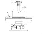
図1は透視撮影台の最小構成要素を示す。被検者をのせるテーブル1とその上部にX線を発生するX線管装置2とそのX線を受けるイメージインテンシファイアを含む映像系装置3から構成され、透視撮影台の軌跡を小さくするには、X線管装置2と映像系装値3およびテーブル1の中央部であるA点付近に回転中心を持ってくれば良いことがわかる。
【0009】
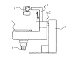
従来の透視撮影台その1では図2に示すように透視撮影台のX線管球支持部4の外側にA点の回転中心を支持する支持脚部5を設けていたが、奥行き寸法が大きくなる欠点があった。
【0010】
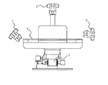
従来型透視撮影台その2では、図3の透視撮影台のテーブル1の下に回転中心を設け、支持脚部5をX線管球支持部4の下に設置しているため、透視撮影台の奥行き寸法が小さくなるが、しかし起倒動作時の軌跡が大きくなる欠点があった。立位時にX線管装置位置6および逆傾時X線管装置位置(−45°時)7がテーブル1横幅より外側に出ていることがわかる。この欠点をカバーするため立位,逆傾位時のX線管球装置と水平時のテーブルとの差分だけ透視撮影台全体を移動する機構を考案した。この機構を追加することにより実際の回転中心はテーブルの下にあっても透視台全体を移動するため仮想中心は図1のA点となるため、透視撮影台の軌跡は小さくなる。
【0011】
図4は、透視撮影台全体を長手方向に移動可能な透視撮影台の外観図を示す。透視撮影台のスライドベース8の長手方向にラック9を設け、起倒駆動用モータ10,起倒駆動用減速機11からチェーン(透視撮影台移動用)12,歯車(大)13,歯車(小)14を介してラック9を駆動する。水平位→逆傾方向に動作するときには、図中aの方向に起倒駆動用減速機11が回転し、チェーン12がb方向に移動し、歯車(大)13がc方向,歯車(小)14がd方向に回転することにより透視撮影台全体が足側方向に移動する。水平位→立位方向に動作するときには、起倒駆動用減速機11、チェーン12、歯車(大)13及び歯車(小)14が前記水平位→逆傾方向と逆回転するように起倒駆動用モータ10を回転させればよい。
【0012】
起倒動時はチェーン(起倒動用)15をe方向に移動することにより起倒回転軸16をf方向に回転させる。この起倒回転軸16がf方向に回転することにより、回転枠17が起動動作する。このまま回転すると支持枠18が床に当たってしまうため、起倒回転軸16から回転枠遊星歯車(上)19にかけたチェーン(回転枠)20をg方向に移動し、回転枠上部17に固定された回転枠遊星歯車(上)19の外部歯車をh方向に回転させる。回転枠17の上下に設けた回転枠遊星歯車(上)19および回転枠歯車(下)21に支持枠チェーン22が掛かっており支持枠連結金具23で支持枠18と連結されており支持枠チェーン22がi方向に移動するため、水平位→逆傾方向動作時に支持枠18を足側方向に移動させる動作をするので逆傾位になっても支持枠18が床に当たらずに済む。水平位→立位方向の動作は、これと逆の動作が行われる。
【0014】
【発明の効果】
このような機構を持った透視撮影台を使用することにより起倒動時の軌跡を最小限にしながら透視撮影台の奥行きも従来型装置よりも小さくしたため、レントゲン車に搭載したときには、透視撮影台を横方向に積み込むことが可能で奥行き方向が短いため、レントゲン車の車体長を短くすることが可能となる。今まで通行が難しかった山間部等にも行けるようになり検診者数を増やすことも可能となる。縦方向に積んだときも透視撮影台の側面に胸部撮影装置を同時に搭載することが可能となり、従来のように別の場所に設置する必要がなくなり結果として車体を短くすることができたり、より多くの検査器具を搭載できるようになり検査効率を上げることができる。
【0015】
又、ビル内開業等で大きな部屋が確保できない場合にも、透視撮影台の長手方向のスペースが少なくてすむため設置が容易になる。従来の撮影室に設置した場合には設置スペースが少ないため、近年増大している検診器具を室内に設置することも可能となる。
【0016】
従来型の透視撮影台は起倒動時の動作範囲が大きいため透視撮影台近辺に近接操作卓,いす等を置いたときに起倒動作に伴い接触し、壊すこともあった。この機構を使用した透視撮影台では起倒回転範囲がわかりやすく透視撮影台近辺に各種器具を設置していても、接触して壊す可能性が少ない。
【図面の簡単な説明】
【図1】透視撮影台の最小構成を説明する図。
【図2】従来型装置その1で起倒動作軌跡は小さいが奥行きがある例。
【図3】従来型装置その2で奥行きは小さいが起倒動作範囲が大きい例。
【図4】本発明の起倒動時に透視撮影台全体を長手方向に移動する機構を持つ透視撮影台。
【符号の説明】
1 テーブル
2 X線管装置
3 映像系装置
4 X線管球支持部
5 支持脚部
6 立位時X線管装置位置
7 逆倒位時X線管装置位置
8 スライドベース
9 ラック
10 起倒駆動用モータ
11 起倒駆動用減速機
12 チェーン(移動用)
13 歯車(大)
14 歯車(小)
15 チェーン(起倒動用)
16 起倒回転軸
17 回転枠
18 支持枠
19 回転枠遊星歯車(上)
20 チェーン(回転枠)
21 回転枠歯車(下)
22 支持枠チェーン
23 支持枠連結金具[0001]
BACKGROUND OF THE INVENTION
The present invention relates to a fluoroscopic imaging table for performing a stomach examination using X-rays, and more particularly, to a fluoroscopic imaging table with a reduced tilting range and depth for in-vehicle use.
[0002]
[Prior art]
In a conventional in-car fluoroscopic imaging table, there is an axis center that tilts the fluoroscopic imaging table outside the mounted rapid-viewing unit, and the trajectory at the time of tilting is compact because it tilts around that axis. There is a disadvantage that the depth of the fluoroscopic imaging table that requires a leg part that holds the tilting central axis provided outside the speed shooting unit is widened, and when this fluoroscopic imaging table is mounted vertically, the fluoroscopic imaging table is loaded There was no space for other units on the side, and at the same time, it was not possible to meet the demand to install a chest imaging device.
[0003]
In addition, a device provided with legs at the lower portion of the speed-taking section to be mounted has a wide range of raising / lowering and cannot be mounted laterally in the bus car.
[0004]
[Problems to be solved by the invention]
By making the length direction when the fluoroscopic imaging table for X-ray cars is tilted up to 2300mm or less of the width of the bus inside the bus, it is possible to horizontally stack, and the depth is also increased from about 1700mm to about 1400mm. It is an object of the present invention to provide a fluoroscopic imaging table that can improve space efficiency by simultaneously loading a chest imaging device on the side surface.
[0005]
[Means for Solving the Problems]
The above-mentioned purpose is to move the whole fluoroscopic imaging table to the head side of the subject when the bed on which the subject is placed is in a horizontal position in the standing position, and from the horizontal position to the reverse tilt direction. This is achieved by providing a slide mechanism for moving the whole fluoroscopic imaging table on the foot side of the subject when the body is tilted .
[0006]
Move the entire fluoroscopic imaging table upside down and simultaneously move the entire fluoroscopic imaging table to the head side when standing, and to the foot side when tilting backwards, while minimizing the range of movement when tilting the legs, Since it can be installed underneath, the depth is also more compact than the conventional device.
[0007]
For this reason, it can be installed horizontally in a bus with limited installation space, so there is room in the vehicle's vertical direction. In some cases, there is a need to shorten the vehicle body or to install other inspection equipment. Can also answer. In addition, when mounted in the bus in the vertical direction, a chest radiographing device or the like can be installed on the side of the fluoroscopic table, which facilitates the placement of inspection equipment.
[0008]
DETAILED DESCRIPTION OF THE INVENTION
FIG. 1 shows the minimum components of a fluoroscopic imaging table. It is composed of a table 1 on which a subject is placed, an
[0009]
In the conventional fluoroscopic imaging table 1, as shown in FIG. 2, the support leg portion 5 that supports the center of rotation of the point A is provided outside the X-ray tube support portion 4 of the fluoroscopic imaging table. There was a drawback.
[0010]
In the conventional fluoroscopic imaging table 2, the rotation center is provided under the table 1 of the fluoroscopic imaging table in FIG. 3 and the support leg 5 is installed under the X-ray tube support 4. However, there is a drawback that the trajectory at the time of raising and lowering becomes large. It can be seen that the X-ray tube device position 6 and the X-ray tube device position 7 at the time of reverse tilt (at −45 °) 7 are located outside the horizontal width of the table 1 when standing. In order to cover this drawback, we have devised a mechanism that moves the entire fluoroscopic imaging table by the difference between the X-ray tube device during standing and reverse tilting and the horizontal table. By adding this mechanism, even if the actual center of rotation is below the table, the entire fluoroscopic table moves, so the virtual center becomes point A in FIG. 1, and the locus of the fluoroscopic table becomes small.
[0011]
FIG. 4 shows an external view of a fluoroscopic imaging table that can move the entire fluoroscopic imaging table in the longitudinal direction. A rack 9 is provided in the longitudinal direction of the
[0012]
At the time of raising / lowering, the raising / lowering rotating
[0014]
【The invention's effect】
By using a fluoroscopic imaging table with such a mechanism, the depth of the fluoroscopic imaging table is made smaller than conventional devices while minimizing the trajectory during tilting, so when mounted on an X-ray vehicle, the fluoroscopic imaging table Since the depth direction is short and the length of the X-ray vehicle can be shortened. It becomes possible to go to mountainous areas where it was difficult to pass until now, and it is also possible to increase the number of examinees. Even when stacked vertically, it is possible to mount a chest imaging device on the side of the fluoroscopic imaging table at the same time, eliminating the need to install it in another place as in the past, resulting in a shorter vehicle body, and more Many inspection instruments can be installed, and inspection efficiency can be increased.
[0015]
In addition, even when a large room cannot be secured due to opening of the building or the like, installation in the longitudinal direction of the fluoroscopic imaging table can be reduced and the installation becomes easy. Since the installation space is small when installed in a conventional radiographing room, it is also possible to install examination instruments that have been increasing in recent years.
[0016]
The conventional fluoroscopic imaging table has a large operating range when it is tilted, so when a proximity console or chair is placed near the fluoroscopic imaging table, it may come in contact with the tilting operation and break. In the fluoroscopic imaging table using this mechanism, even if various instruments are installed in the vicinity of the fluoroscopic imaging table in which the up and down rotation range is easy to understand, there is little possibility of contact and breaking.
[Brief description of the drawings]
FIG. 1 is a diagram illustrating a minimum configuration of a fluoroscopic imaging table.
FIG. 2 shows an example of the conventional apparatus 1 that has a small up / down motion locus but a depth.
FIG. 3 shows an example of a conventional apparatus No. 2 with a small depth but a large tilting range.
FIG. 4 is a fluoroscopic imaging table having a mechanism for moving the entire fluoroscopic imaging table in the longitudinal direction when it is tilted according to the present invention.
[Explanation of symbols]
DESCRIPTION OF SYMBOLS 1 Table 2
13 Gear (Large)
14 Small gear
15 Chain (for tilting movement)
16 Rotating
20 Chain (Rotating frame)
21 Rotating frame gear (bottom)
22
Claims (2)
前記モータ(10)の動力を伝達する第1のチェーン(15)と、前記第1のチェーン(15)によって回転する第1の回転部(16)と、前記第1の回転部(16)の回転によって起倒動作が行なわれる回転枠(17)とを含み、前記モータ(10)の動力に基づく前記回転枠(17)の起倒動作により撮影台を起倒する回転機構と、
前記モータ(10)の動力を伝達する第2のチェーン(12)と、前記第2のチェーン(12)によって回転する第1の歯車(13)(14)とを含み、前記モータ(10)の動力に基づく前記第1の歯車(13)(14)の回転動作により、撮影台をスライドベースに対して長手方向にスライドさせるスライド機構とを備えることを特徴とする透視撮影台。A motor (10);
A first chain (15) for transmitting power of the motor (10), a first rotating part (16) rotated by the first chain (15), and a first rotating part (16). rotary frame electromotive倒動operation is performed by rotating the (17) seen including a force Taosuru rotating mechanism shooting stand by raising倒動operation of the rotary frame based on the power of the motor (10) (17),
A second chain (12) for transmitting the power of the motor (10); and first gears (13) (14) rotated by the second chain (12 ); A fluoroscopic imaging table comprising: a slide mechanism that slides the imaging table in a longitudinal direction with respect to a slide base by rotating the first gears (13) and (14) based on power .
Priority Applications (1)
| Application Number | Priority Date | Filing Date | Title |
|---|---|---|---|
| JP36624297A JP4149019B2 (en) | 1997-12-25 | 1997-12-25 | Fluoroscopic table |
Applications Claiming Priority (1)
| Application Number | Priority Date | Filing Date | Title |
|---|---|---|---|
| JP36624297A JP4149019B2 (en) | 1997-12-25 | 1997-12-25 | Fluoroscopic table |
Publications (2)
| Publication Number | Publication Date |
|---|---|
| JPH11188031A JPH11188031A (en) | 1999-07-13 |
| JP4149019B2 true JP4149019B2 (en) | 2008-09-10 |
Family
ID=18486288
Family Applications (1)
| Application Number | Title | Priority Date | Filing Date |
|---|---|---|---|
| JP36624297A Expired - Fee Related JP4149019B2 (en) | 1997-12-25 | 1997-12-25 | Fluoroscopic table |
Country Status (1)
| Country | Link |
|---|---|
| JP (1) | JP4149019B2 (en) |
Families Citing this family (3)
| Publication number | Priority date | Publication date | Assignee | Title |
|---|---|---|---|---|
| CN1315435C (en) * | 2004-07-23 | 2007-05-16 | 于红林 | Car carried medical digital X-ray unit |
| US10058291B2 (en) * | 2012-09-13 | 2018-08-28 | Shimadzu Corporation | Radiographic apparatus |
| CN107874777A (en) * | 2017-11-15 | 2018-04-06 | 张福全 | A kind of CT aids in bed apparatus |
-
1997
- 1997-12-25 JP JP36624297A patent/JP4149019B2/en not_active Expired - Fee Related
Also Published As
| Publication number | Publication date |
|---|---|
| JPH11188031A (en) | 1999-07-13 |
Similar Documents
| Publication | Publication Date | Title |
|---|---|---|
| US5475885A (en) | Couch system for x-ray diagnosis | |
| US6789941B1 (en) | Dual C-arm angiographic device for flat panel receptor | |
| JP2001145615A (en) | C-shaped arm x-ray device | |
| US5570409A (en) | Apparatus for X-ray fluoroscopy and fluorography | |
| JP4149019B2 (en) | Fluoroscopic table | |
| JP4187829B2 (en) | X-ray examination apparatus with tiltable patient table | |
| JP3219818B2 (en) | Patient examination table | |
| JP2004503287A (en) | Surgery-diagnosis device with couch device for treatment and / or examination objects | |
| JP3640172B2 (en) | X-ray fluoroscopy table | |
| JPH07194584A (en) | Equipment apparatus for x-ray inspection | |
| JPH02102642A (en) | Rotary radioactive ray apparatus | |
| JP4359366B2 (en) | Radiation equipment | |
| JP4461666B2 (en) | X-ray fluoroscopic equipment | |
| JP2004065807A (en) | Roentgenography system | |
| JP2000070249A5 (en) | ||
| CN101589955A (en) | X-ray apparatus and the method that is used to regulate this device | |
| JP3695879B2 (en) | X-ray equipment | |
| JP4392872B2 (en) | X-ray equipment | |
| JPH07155315A (en) | X-ray examination apparatus | |
| JPS6128565Y2 (en) | ||
| JPH0810249A (en) | X-ray ct device | |
| JPS63153051A (en) | Control system of x-ray fluoroscopic imaging stand | |
| JP3986630B2 (en) | X-ray fluoroscopy table | |
| JP2006122489A (en) | Fluoroscopic photography apparatus | |
| JP2001128966A (en) | Radiographing apparatus |
Legal Events
| Date | Code | Title | Description |
|---|---|---|---|
| A521 | Request for written amendment filed |
Free format text: JAPANESE INTERMEDIATE CODE: A523 Effective date: 20041216 |
|
| A621 | Written request for application examination |
Free format text: JAPANESE INTERMEDIATE CODE: A621 Effective date: 20041216 |
|
| A977 | Report on retrieval |
Free format text: JAPANESE INTERMEDIATE CODE: A971007 Effective date: 20071025 |
|
| A131 | Notification of reasons for refusal |
Free format text: JAPANESE INTERMEDIATE CODE: A131 Effective date: 20071105 |
|
| A521 | Request for written amendment filed |
Free format text: JAPANESE INTERMEDIATE CODE: A523 Effective date: 20071225 |
|
| A131 | Notification of reasons for refusal |
Free format text: JAPANESE INTERMEDIATE CODE: A131 Effective date: 20080303 |
|
| A521 | Request for written amendment filed |
Free format text: JAPANESE INTERMEDIATE CODE: A523 Effective date: 20080422 |
|
| TRDD | Decision of grant or rejection written | ||
| A01 | Written decision to grant a patent or to grant a registration (utility model) |
Free format text: JAPANESE INTERMEDIATE CODE: A01 Effective date: 20080624 |
|
| A01 | Written decision to grant a patent or to grant a registration (utility model) |
Free format text: JAPANESE INTERMEDIATE CODE: A01 |
|
| A61 | First payment of annual fees (during grant procedure) |
Free format text: JAPANESE INTERMEDIATE CODE: A61 Effective date: 20080625 |
|
| FPAY | Renewal fee payment (event date is renewal date of database) |
Free format text: PAYMENT UNTIL: 20110704 Year of fee payment: 3 |
|
| R150 | Certificate of patent or registration of utility model |
Free format text: JAPANESE INTERMEDIATE CODE: R150 |
|
| FPAY | Renewal fee payment (event date is renewal date of database) |
Free format text: PAYMENT UNTIL: 20120704 Year of fee payment: 4 |
|
| FPAY | Renewal fee payment (event date is renewal date of database) |
Free format text: PAYMENT UNTIL: 20120704 Year of fee payment: 4 |
|
| FPAY | Renewal fee payment (event date is renewal date of database) |
Free format text: PAYMENT UNTIL: 20130704 Year of fee payment: 5 |
|
| LAPS | Cancellation because of no payment of annual fees |