JP4139046B2 - Game machine - Google Patents
Game machine Download PDFInfo
- Publication number
- JP4139046B2 JP4139046B2 JP2000159456A JP2000159456A JP4139046B2 JP 4139046 B2 JP4139046 B2 JP 4139046B2 JP 2000159456 A JP2000159456 A JP 2000159456A JP 2000159456 A JP2000159456 A JP 2000159456A JP 4139046 B2 JP4139046 B2 JP 4139046B2
- Authority
- JP
- Japan
- Prior art keywords
- control device
- abnormality
- game
- discharge
- power failure
- Prior art date
- Legal status (The legal status is an assumption and is not a legal conclusion. Google has not performed a legal analysis and makes no representation as to the accuracy of the status listed.)
- Expired - Fee Related
Links
Images


Landscapes
- Pinball Game Machines (AREA)
Description
【0001】
【発明の属する技術分野】
本発明は、電源遮断時に遊技制御装置ならびに排出制御装置における制御情報、異常監視情報を記憶保持可能な記憶保持手段を備えた遊技機に関する。
【0002】
【従来の技術】
従来、遊技機(パチンコ遊技機)は、制御用のプログラムの実行にしたがって遊技の進行を制御する遊技制御装置が設けられている。また、遊技領域の入賞口に遊技球が入賞した場合、遊技制御装置からの情報に基づいて、貯留タンク側の遊技球を排出装置より遊技者側(遊技機前面側の上皿等)へ所要数排出するように制御する排出制御装置が設けられている。
【0003】
【発明が解決しようとする課題】
このような遊技機において、遊技が行われている最中に、停電等が発生して遊技機への電力の供給が絶たれた場合には、遊技機の遊技状態がどのような状態であったかに関する情報が消滅してしまい、電力の供給が再開されても、停電発生時に実行されていた状態から遊技を再開することができず、停電発生に伴う遊技者への補償ができないという不都合が生じる。
【0004】
そこで、電力の供給が絶たれたときに遊技制御装置ならびに排出制御装置における情報の記憶を保持するための記憶保持手段を設けることが提案されている。
【0005】
しかし、この場合次のような問題が懸念される。遊技制御装置等は特定のセンサにより異常を監視して、所定時間異常を検出すると、異常と判定すると共に、排出に関する異常の場合、遊技球の排出を中止する等の異常処理を行うようになっている。そのため、異常の確定前(検出途中)に停電した場合、停電から復帰したときは正常な状態で復帰するのに対して、その後直ぐに異常が確定して異常処理に入ることになる。このように、一旦正常な状態で復帰した後直ぐに異常処理に入るのでは、遊技者に違和感を与える。
【0006】
一方、センサの状態は、停電中の遊技店の従業員の操作、遊技者が遊技台を叩く等の行為、あるいは自然に遊技機内の球が球崩れすること等の人為的、物理的要因によって、状態変化する可能性があり、停電前と停電復帰時とで必ずしも一致しないことがある。したがって、停電前に異常が有った場合、停電中に異常が解消されても、停電から復帰したときに、異常有りと誤って判断しかねない。特にこのようなとき、異常の報知を行ったのでは、遊技者に不信感を与えてしまう。 本発明は、このような問題点を解決することを目的とする。
【0007】
【課題を解決するための手段】
第1の発明は、遊技の進行を管理する遊技制御装置を備え、前記遊技制御装置は、異常監視を行い、異常となった場合はその異常を示すフラグを当該遊技制御装置のRAMに設定する異常監視情報にセットし、遊技機の停電発生時にバックアップ回路より前記遊技制御装置のRAMにバックアップ電源を供給して当該RAMのデータをバックアップする遊技機において、前記遊技制御装置は、異常監視に用いるセンサの検出信号に基づいて監視タイマをスタートし、前記検出信号が異常状態のまま監視タイマがタイムアップすると異常であると判定して、その異常を示すフラグを異常監視情報にセットし、前記停電が発生した場合は、バックアップされるRAMのデータに含まれる異常監視情報に、停電から復帰後の遊技の進行が開始されるまでに前記異常を示すフラグをセットし、該停電から復帰後の遊技の進行が開始されるまでに、前記異常監視に用いるセンサの検出信号に基づいて異常監視を行う。
【0008】
第2の発明は、貯留タンク側より導かれる遊技球を遊技者側へ排出する機構を設けた排出装置と、前記遊技制御装置から出力される制御情報に基づいて前記排出装置の遊技球の排出を制御する排出制御装置と、を備え、前記遊技制御装置は、停電から復帰後の遊技の進行が開始されるまでに前記異常監視により異常であると判定した場合は、前記排出制御装置に異常監視情報のうち不正フラグ情報を出力し、前記排出制御装置は、前記遊技制御装置からの不正フラグ情報に基づいて前記排出装置の遊技球の排出を中止させることを特徴とする。
【0009】
第3の発明は、前記遊技制御装置は、停電から復帰後の遊技の進行が開始されるまでに前記異常監視に用いるセンサの検出信号に基づいて監視タイマにより異常監視を行い、該検出信号が正常状態のまま監視タイマがタイムアップすると正常であると判定して、前記異常を示すフラグをクリアし、かつ、前記排出制御装置に異常監視情報のうち正常フラグ情報を出力し、前記排出制御装置は、前記遊技制御装置からの正常フラグ情報に基づいて前記排出装置の遊技球の排出を再開することを特徴とする。
【0020】
【発明の効果】
第1の発明では、異常状態が確定する前に停電が発生した場合、停電から復帰したときに、一旦正常な状態で復帰した後直ぐに異常状態が確定して異常処理に入ってしまうことを回避でき、遊技者を混乱させたり、遊技者に違和感を与えることはない。
【0021】
第2の発明では、遊技制御装置は、停電から復帰後の遊技の進行が開始されるまでに前記異常監視により異常であると判定した場合は、排出制御装置に異常監視情報のうち不正フラグ情報を出力し、排出制御装置は、遊技制御装置からの不正フラグ情報に基づいて排出装置の遊技球の排出を中止させることができる。
【0023】
第3の発明では、停電から復帰後の遊技の進行が開始されるまでに、異常状態にあるか正常状態にあるかを確認した後、正確に速やかに処理を再開することができる。
【0027】
【発明の実施の形態】
以下、添付図面に基づいて、本発明の実施の形態について説明する。
【0028】
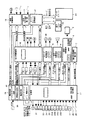
図1は遊技機(パチンコ遊技機)1の裏側を示すもので、機前面枠のフレーム2内に取付けられる遊技盤(図示されない)の裏面側には、遊技盤の遊技領域に設けられた各入賞装置の入賞球を案内する入賞球集合カバー(図示されない)、可変表示装置3(図2参照)を制御する表示制御装置4、遊技盤ならびに機前面枠の装飾用のランプ等を制御する装飾制御装置5、音制御装置6、盤用外部接続端子盤(遊技盤側からのセンサ等の信号出力用)7等が取り付けられる。
【0029】
機前面枠の裏面側には、フレーム2裏面に取付けられる裏機構盤8の上部に、外部から電源を取り入れるターミナル基板10、枠用外部接続端子盤(各制御装置等からの信号出力用ならびに遊技店の管理装置からの信号受信用)11、遊技球を貯留する球貯留タンク12、球貯留タンク12の球を整列誘導するシュート13が取り付けられる。
【0030】
裏機構盤8の右側にはシュート13が誘導した球を機前面の上皿、下皿に払い出す払出ユニット(排出装置)14が、裏機構盤8の左側には各制御装置等に電源を供給する電源装置15が取り付けられる。
【0031】
裏機構盤8の下部には、払出ユニット14を制御する排出制御装置16、遊技の進行を管理する遊技制御装置17、打球発射装置を制御する発射制御装置18が取り付けられる。
【0032】
なお、20はカード球貸しユニット、21はカード球貸しユニット用接続基板である。
【0033】
図2は制御系のブロック構成を示すもので、遊技制御装置(主基板)17、排出制御装置(払出制御基板)16、表示制御装置(表示制御基板)4、装飾制御装置(ランプ制御基板)5、音制御装置(音声制御基板)6、発射制御装置(発射制御基板)18、電源装置(電源基板)15等からなる。
【0034】
遊技制御装置17は、制御用のプログラムおよび遊技盤の遊技領域の各入賞装置に設けられた各種センサ(例えば、可変表示装置4における変動表示ゲームの始動センサ22、入賞センサ23A〜23N、大入賞口のカウントセンサ24、継続センサ25等)、払出ユニット14の排出球を導く排出樋のオーバーフロー流路(上皿と下皿を結ぶ流路)のオーバーフロー状態を検出するためのオーバーフローセンサ26(図1参照)、球貯留タンク12の球を払出ユニット14へ整列誘導するシュート13の球切れ(球無し)を検出するためのシュート球切れセンサ27(図1参照)、遊技盤を覆う機前面のガラス枠の開放を検出するためのガラス枠開放センサ28、払出ユニット14が賞球として排出した排出球を検出するための賞球検出センサ30の検出信号に基づいて、例えば可変表示装置3における変動表示ゲームの大当たりの抽選、各種異常の判定等を行うと共に、各種制御装置(排出制御装置16、表示制御装置4、装飾制御装置5、音制御装置6、発射制御装置18)、遊技盤に設けられた各種役物装置(例えば、大入賞口ソレノイド31等)に各情報を送信することにより、遊技を統括的に制御する。
【0035】
賞球に関しては、遊技球が遊技領域の各入賞装置に入賞すると、入賞装置に基づき賞球数を設定してある所定の賞球制御情報を排出制御装置16へ送信する。
【0036】
また、賞球検出センサ30の検出信号に基づき、払出ユニット14から所定時間内に所要数の賞球が排出されたかどうか(賞球時)、オーバーフローセンサ26の検出信号に基づき、オーバーフロー流路のオーバーフロー状態が所定時間続いたかどうか、シュート球切れセンサ27の検出信号に基づき、シュート13の球切れが所定時間続いたかどうか、ガラス枠開放センサ28の検出信号に基づき、ガラス枠の開放が所定時間続いたかどうか等の異常監視を行い、異常監視情報を排出制御装置16、表示制御装置4等へ送信する。
【0037】
図3に遊技制御装置17のRAMに設定する異常監視情報の作業領域の例を示す。賞球時、オーバーフローセンサ26のON時、シュート球切れセンサ27のON時、ガラス枠開放センサ28のON時、該当する監視タイマをスタートして、異常状態のまま監視タイマがタイムアップすると、該当する異常と判定して、その異常(異常確定状態)を示す不正フラグをセットする。払出ユニット14から排出された賞球数が過剰なときも、異常と判定して、その異常(異常確定状態)を示す不正フラグをセットする。異常の場合、異常監視情報のうち、不正フラグ情報を送信すると共に、停電復帰時を除き、表示器、ランプ、音声等の不正コマンドを送信する。
【0038】
また、オーバーフローセンサ26のOFF時、シュート球切れセンサ27のOFF時、ガラス枠開放センサ28のOFF時、該当する監視タイマをスタートして、OFF状態のまま監視タイマがタイムアップすると、正常と判定して、該当する不正フラグをクリアする。正常の場合、異常監視情報のうち、正常フラグ情報、表示器、ランプ、音声等の正常コマンドを送信する。
【0039】
表示制御装置4は、遊技制御装置17からの表示制御情報に基づいて可変表示装置3における表示を制御する。例えば、変動表示ゲームの場合、可変表示装置3の複数の可変表示領域に複数の識別情報(図柄)を変動表示すると共に、所定時間後に変動表示を停止する制御を行う。また、大当たりが発生した場合、大当たりの遊技の進行に対応した画像を表示する。また、停電復帰時に所定の画像を表示する。
【0040】
排出制御装置16は、遊技制御装置17からの賞球制御情報またはカード球貸しユニット20からの貸球要求に基づいて、払出ユニット14(排出用パルスモータ)の動作を制御し、所要数の賞球または貸球の排出を行わせる。
【0041】
また、遊技制御装置17からの異常監視情報に基づき、払出ユニット14からの排出賞球数が不足したとき、過剰なとき、オーバーフロー流路がオーバーフロー状態のとき、シュート13が球切れのとき、ガラス枠が開放しているとき、払出ユニット14の球の排出を中止する異常処理を行う。
【0042】
また、排出制御装置16にカード球貸しユニット20、操作パネル基板32が接続されているかどうか、払出ユニット14が貸球として排出した排出球を検出するための貸球検出センサ33の検出信号に基づき、球貸し時に払出ユニット14から所定時間内に所要数の貸球が排出されたかどうか等の異常監視を行う。
【0043】
図4に排出制御装置16のRAMに設定する異常監視情報の作業領域の例を示す。排出制御装置16にカード球貸しユニット20が未接続のとき、異常と判定して、不正フラグをセットする。球貸し時、監視タイマをスタートして、異常状態(排出貸球数の異常)のまま監視タイマがタイムアップすると、異常と判定して、不正フラグをセットする。なお、異常の場合、7セグメントLED(排出制御装置16に設けている)による報知を行うようにしても良い。
【0044】
装飾制御装置5は、各装飾用ランプ、LED等の装飾発光装置を制御すると共に、例えば可変表示装置4における変動表示ゲームの始動記憶表示器34等の表示を制御する。音制御装置6は、音出力装置からの効果音出力を制御する。発射制御装置18は、打球発射装置を制御する。
【0045】
電源装置15は、外部からの交流電源を直流電源等に変換して各種装置に供給する装置であり、バックアップ回路35、停電検出回路36を備えている。
【0046】
停電検出回路36は、停電時に電源装置15にて所定の電圧降下を検出すると、停電検出信号、リセット信号を順に、遊技制御装置17、排出制御装置16等に出力する。遊技制御装置17、排出制御装置16は、停電検出信号を受けると、所定の停電処理を行い、リセット信号を受けると、CPUの動作を停止する。
【0047】
バックアップ回路35は、遊技制御装置17および排出制御装置16のRAMにバックアップ電源を供給して、RAMのデータ(遊技データ、賞球データ、異常監視データ)をバックアップする。即ち、停電時に遊技制御装置17は、遊技に関する制御情報(例えば、変動表示ゲームの情報、大当たりの遊技の情報、各種制御装置の情報等)、賞球に関する制御情報(賞球数等)、異常監視情報(図3の情報)を記憶保持する。また、停電時に排出制御装置16は、賞球に関する制御情報(未処理の賞球数等)、異常監視情報(遊技制御装置17からの異常監視情報ならびに図4の情報)を記憶保持する。
【0048】
そして、遊技制御装置17および排出制御装置16は、停電が発生した場合、このように記憶保持した情報のうち所定の異常監視情報、即ち遊技球の排出条件(排出開始条件)に関する異常監視情報(オーバーフローフラグ情報、シュート球切れフラグ情報)およびその他の異常監視情報(ガラス枠開放フラグ情報)を、停電復帰後の遊技の進行が開始されるまでに、異常確定状態(不正フラグ情報)に設定する。
【0049】
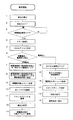
図5は、遊技制御装置17における停電復帰時に、前記所定の異常監視情報を異常確定状態に設定するフローの例を示すものである。
【0050】
電源が投入され、動作が開始されると、ステップ1〜3にて割込を禁止し、全出力をOFFにして、電源が安定するまで(停電検出信号がOFFになるまで)待つ。
【0051】
ステップ4,5では、CPUの初期化を行い、RAMのアクセスを許可する。
【0052】
ステップ6では、停電の復旧か、通常の電源投入かを判定する。この場合、RAMの所定のバックアップ領域のチェックデータが正常値のとき停電の復旧、異常値のとき通常の電源投入と判定する。
【0053】
通常の電源投入の場合、ステップ14〜19に進み、ステップ14,15では、全RAM領域のデータ(制御情報、異常監視情報)をクリア(無効化)し、初期値を設定する。
【0054】
ステップ16では、通常の電源投入時のコマンドを各種制御装置に送信する。
【0055】
ステップ17では、スタックポインタを設定し、ステップ18では、割込を許可し、通常処理へ移行する。
【0056】
一方、停電復旧の場合、ステップ7〜13に進み、ステップ7,8では、停電復旧時に異常確定状態に設定すべきRAM領域のデータ(前記所定の異常監視情報)を異常確定状態に設定する。
【0057】
ステップ9では、停電復旧時のコマンドを各種制御装置に送信する。このコマンドの送信によって、遊技制御装置17の制御開始を各種制御装置が把握できる。また、可変表示装置3の後述する報知画面の立ち上がりが早くなる。
【0058】
ステップ10では、全レジスタを復帰し、ステップ11では、スタックポインタを復帰する。ステップ12では、割込を許可し、ステップ13では、停電発生時の中断アドレスへ復帰して、制御を開始する。
【0059】
なお、排出制御装置16は、ステップ16、ステップ9を除いて、同様の処理を行う。
【0060】
このように構成したため、停電から復帰すると、遊技制御装置17は、オーバーフローセンサ26、シュート球切れセンサ27、ガラス枠開放センサ28の検出信号に基づき、オーバーフロー流路がオーバーフロー状態かどうか、シュートが球切れかどうか、ガラス枠が開放かどうかの異常監視を行い、排出制御装置16は、異常確定状態に設定した異常監視情報に基づき、異常処理を行う。
【0061】
停電復帰時、遊技制御装置17は、表示器、ランプ、音声等の不正コマンドを送信せず、異常報知を禁止する。
【0062】
そして、遊技制御装置17は、図6のように、オーバーフローセンサ26、シュート球切れセンサ27、ガラス枠開放センサ28(図示省略)がOFF(物理状態OFF)状態のまま該当する監視タイマがタイムアップすると、正常と判定して、異常確定状態に設定してある不正フラグ情報をクリア(論理状態OFF)して、該当する正常フラグ情報を排出制御装置16、表示制御装置4等へ送信し、排出制御装置16は、その正常フラグ情報に基づき該当する不正フラグ情報(異常確定状態)をクリアするが、この際1番長い監視タイマ(例えば、オーバーフローの監視タイマ)がタイムアップして、排出制御装置16が該当正常フラグ情報を受信するまでは、遊技球の排出条件(排出開始条件)は不許可、つまり排出制御装置16は異常処理を続ける。
【0063】
そのため、従来のように、オーバーフローあるいはシュートの球切れあるいはガラス枠開放の異常の確定前(センサON状態の監視タイマのカウント中)に停電した場合、停電から復帰したときに、一旦正常な状態で復帰した後直ぐにオーバーフローあるいはシュート球切れあるいはガラス枠開放の異常が確定して異常処理に入ってしまうことを回避でき、したがって遊技者を混乱させたり、遊技者に違和感を与えることはない。
【0064】
この一方、異常監視に用いるオーバーフローセンサ26、シュート球切れセンサ27、ガラス枠開放センサ28の状態が、人為的あるいは物理的要因によって、停電前と停電復帰時とで変化した場合、例えば停電前にオーバーフロー流路のオーバーフローの異常が有り、停電中に遊技店の従業員の操作や遊技者の操作によってオーバーフロー状態が解消された場合、本例では、停電から復帰したときに排出制御装置16が異常処理を行うが、この異常処理は払出ユニット14の球の排出を中止するのみであり、表示器、ランプ、音声等による異常報知は行わないので、遊技者に不信感を与えることはない。
【0065】
そして、遊技制御装置17は、図6のように、オーバーフローセンサ26、シュート球切れセンサ27、ガラス枠開放センサ28(図示省略)がOFF(物理状態OFF)状態のまま該当する監視タイマがタイムアップすると、正常と判定して、異常確定状態に設定してある不正フラグ情報をクリア(論理状態OFF)して、該当する正常フラグ情報を排出制御装置16、表示制御装置4等へ送信し、排出制御装置16は、その正常フラグ情報に基づき該当する不正フラグ情報(異常確定状態)をクリアすると共に、この際1番長い監視タイマ(例えば、オーバーフローの監視タイマ)がタイムアップして、排出制御装置16が該当正常フラグ情報を受信すると、遊技球の排出条件(排出開始条件)が許可、つまり払出ユニット14の球の排出を許可する。
【0066】
したがって、停電から復帰した場合、オーバーフロー、シュートの球切れ、ガラス枠開放の異常が無いときは、これらの確認後、速やかに排出処理を再開することができる。
【0067】
なお、停電から復帰した場合、オーバーフローあるいはシュートの球切れあるいはガラス枠開放の異常が有るときは、1番長い監視タイマ(例えば、オーバーフローの監視タイマ)のタイムアップ後、遊技制御装置17からの不正コマンドに基づき表示器、ランプ、音声等による異常報知が行われ、排出制御装置16による異常処理が行われる。
【0068】
なお、異常監視情報を停電復帰時に異常確定状態に設定するので、停電復帰時に停電前の状態を確認および報知可能である。実際、停電復帰後も停電前の状態が続いている可能性が高いことから、その報知を行うようにすれば、停電前の異常状態について速やかに対応できる。
【0069】
図7は、本発明の第2の実施の形態を示す。これは、遊技制御装置17および排出制御装置16が、停電発生時に、記憶保持する所定の異常監視情報、即ち遊技球の排出条件(排出開始条件)に関する異常監視情報(オーバーフローフラグ情報、シュート球切れフラグ情報)およびその他の異常監視情報(ガラス枠開放フラグ情報)を異常確定状態(不正フラグ情報)に設定するもので、停電検出回路36からの停電検出信号を受けると実行する停電処理にて行う。
【0070】
停電処理に入ると、ステップ21にて全出力をOFFする。
【0071】
ステップ22,23では、停電時に異常確定状態に設定すべきRAM領域のデータ(前記所定の異常監視情報)を異常確定状態に設定する。
【0072】
ステップ24〜26では、スタックポインタ、停電発生時の中断アドレス、全レジスタをセーブ(制御情報、異常監視情報を記憶保持)する。
【0073】
ステップ27では、RAMのアクセスを禁止する。
【0074】
このようにすれば、停電復帰時の処理負担を軽減できると共に、停電復帰後に速やかに異常、正常判定を行える。
【0075】
なお、遊技制御装置17、排出制御装置16における異常監視情報(オーバーフローフラグ情報、シュート球切れフラグ情報、ガラス枠開放フラグ情報)の異常確定状態の設定は、停電発生時ならびに停電復帰時に繰り返し、あるいは分散して行っても良い。
【0076】
また、停電から復帰したときに、遊技制御装置17が、異常確定状態の異常監視情報(オーバーフロー不正フラグ情報、シュート球切れ不正フラグ情報、ガラス枠開放不正フラグ情報)を排出制御装置16へ送信するようにした場合、排出制御装置16における異常監視情報(オーバーフローフラグ情報、シュート球切れフラグ情報、ガラス枠開放フラグ情報)の異常確定状態の設定を行わなくても良い。
【0077】
また、排出制御装置16における異常監視情報(オーバーフローフラグ情報、シュート球切れフラグ情報、ガラス枠開放フラグ情報)の異常確定状態の設定のみを行い、停電から復帰した際には、遊技制御装置17が、異常監視情報(オーバーフローフラグ情報、シュート球切れフラグ情報、ガラス枠開放フラグ情報)を排出制御装置16へ送信しないようにしても良い。
【0078】
実施の形態では、遊技機としてパチンコ遊技機に適用した例を示したが、その他の遊技機、例えばパチスロ、アレンジボール等の遊技機にも適用できる。
【0079】
なお、今回開示された実施の形態は全ての点で例示であって制限的なものではないと考えられるべきである。本発明の範囲は上記した説明ではなくて特許請求の範囲によって示され、特許請求の範囲と均等の意味および範囲内での全ての変更が含まれることが意図される。
【図面の簡単な説明】
【図1】本発明の実施の形態における遊技機の裏面図である。
【図2】制御系のブロック構成図である。
【図3】遊技制御装置における異常監視情報の作業領域の例を示す表図である。
【図4】排出制御装置における異常監視情報の作業領域の例を示す表図である。
【図5】制御内容を示すフローチャートである。
【図6】制御タイミングチャートである。
【図7】第2の実施の形態の制御内容を示すフローチャートである。
【符号の説明】
1 遊技機
3 可変表示装置
4 表示制御装置
5 装飾制御装置
6 音制御装置
12 球貯留タンク
13 シュート
14 払出ユニット
15 電源装置
16 排出制御装置
17 遊技制御装置
18 発射制御装置
20 カード球貸しユニット
22 始動センサ
23A〜23N 入賞センサ
24 カウントセンサ
25 継続センサ
26 オーバーフローセンサ
27 シュート球切れセンサ
28 ガラス枠開放センサ
30 賞球検出センサ
31 大入賞口ソレノイド
33 貸球検出センサ
35 バックアップ回路
36 停電検出回路[0001]
BACKGROUND OF THE INVENTION
The present invention relates to a gaming machine provided with a memory holding means capable of storing and holding control information and abnormality monitoring information in a game control device and a discharge control device when the power is shut off.
[0002]
[Prior art]
Conventionally, a gaming machine (pachinko gaming machine) is provided with a game control device that controls the progress of the game in accordance with the execution of a control program. In addition, when a game ball wins a game area winning opening, the storage ball side game ball is required from the discharge device to the player side (the upper plate on the front side of the gaming machine, etc.) based on information from the game control device. A discharge control device that controls the number of discharges is provided.
[0003]
[Problems to be solved by the invention]
In such a gaming machine, if the power supply to the gaming machine is interrupted due to a power outage or the like while the game is being played, what is the gaming state of the gaming machine? Even if the information about the event disappears and the supply of power is resumed, the game cannot be resumed from the state where it was executed at the time of the power failure, and the player cannot be compensated when the power failure occurs. .
[0004]
In view of this, it has been proposed to provide a memory holding means for holding information stored in the game control device and the discharge control device when the supply of power is cut off.
[0005]
However, in this case, the following problems are concerned. A game control device or the like monitors an abnormality with a specific sensor, and when an abnormality is detected for a predetermined time, it is determined as an abnormality, and in the case of an abnormality relating to the discharge, an abnormal process such as stopping the discharge of the game ball is performed. ing. Therefore, when a power failure occurs before the abnormality is confirmed (during detection), when the power is restored from the power failure, the normal state is restored, but thereafter, the abnormality is confirmed and the abnormality processing is started. In this way, once in the fall to immediately abnormal processing after returning in a normal state, give a sense of discomfort to the player.
[0006]
On the other hand, the state of the sensor depends on man-made and physical factors such as the operation of a game shop employee during a power outage, the act of a player hitting the game table, or the ball in the gaming machine naturally collapsing. , There is a possibility that the state will change, and there is a case where it is not always the same before and after the power failure. Therefore, if there is an abnormality before the power failure, even if the abnormality is resolved during the power failure, it may be erroneously determined that there is an abnormality when the power is restored from the power failure. Especially in such a case, if the abnormality is notified, the player will be distrusted. An object of the present invention is to solve such problems.
[0007]
[Means for Solving the Problems]
A first invention includes a game control device that manages the progress of a game, and the game control device monitors an abnormality and sets a flag indicating the abnormality in the RAM of the game control device when an abnormality occurs. In the gaming machine that is set in the abnormality monitoring information and supplies backup power to the RAM of the gaming control apparatus from the backup circuit when a power failure occurs in the gaming machine, the gaming control apparatus is used for abnormality monitoring. A monitoring timer is started based on the detection signal of the sensor, and when the monitoring timer expires while the detection signal is in an abnormal state, it is determined that there is an abnormality, a flag indicating the abnormality is set in the abnormality monitoring information, and the power failure In the event of a failure, the progress of the game after recovery from a power failure is started in the abnormality monitoring information included in the RAM data to be backed up The sets a flag indicating abnormality in, until progression of the game after the return from該停collector is started, the abnormality monitoring based on the detection signal of the sensor used in the abnormality monitoring.
[0008]
According to a second aspect of the present invention, there is provided a discharge device provided with a mechanism for discharging the game ball guided from the storage tank side to the player side, and discharge of the game ball of the discharge device based on control information output from the game control device A discharge control device that controls the discharge control device, and when the game control device determines that an abnormality is detected by the abnormality monitoring before the progress of the game after recovery from a power failure is started, an abnormality is detected in the discharge control device. outputs invalid flag information of the monitoring information, the emission control device is characterized in Rukoto stops the discharge of the game balls of the discharge device on the basis of incorrect flag information from the game control device.
[0009]
According to a third aspect of the present invention, the game control device performs abnormality monitoring by a monitoring timer based on a detection signal of a sensor used for the abnormality monitoring until the progress of the game after recovery from a power failure is started, and the detection signal is When the monitoring timer expires in a normal state, it is determined to be normal, the flag indicating the abnormality is cleared, and normal flag information out of the abnormality monitoring information is output to the discharge control device, and the discharge control device Is characterized in that the discharge of the game ball of the discharge device is restarted based on normal flag information from the game control device.
[0020]
【The invention's effect】
In the first invention, when a power failure occurs before the abnormal state is confirmed , when the power recovers from the power failure, it is avoided that the abnormal state is determined immediately after returning to the normal state and the abnormality processing is started. Yes, it does not confuse the player or give the player a sense of incongruity.
[0021]
In the second invention, when the game control device determines that an abnormality is detected by the abnormality monitoring before the progress of the game after returning from a power failure is started, the flag information in the abnormality monitoring information is sent to the discharge control device. And the discharge control device can stop the discharge of the game ball of the discharge device based on the fraud flag information from the game control device.
[0023]
In the third invention, the process can be restarted accurately and promptly after confirming whether the game is in an abnormal state or in a normal state before the progress of the game after a power failure is started .
[0027]
DETAILED DESCRIPTION OF THE INVENTION
Hereinafter, embodiments of the present invention will be described with reference to the accompanying drawings.
[0028]
FIG. 1 shows the back side of a gaming machine (pachinko gaming machine) 1, and on the back side of a gaming board (not shown) mounted in the
[0029]
On the back side of the machine front frame, on the upper part of the
[0030]
On the right side of the
[0031]
A
[0032]
In addition, 20 is a card ball lending unit and 21 is a card ball lending unit connection board.
[0033]
FIG. 2 shows a block configuration of the control system. The game control device (main board) 17, the discharge control device (payout control board) 16, the display control device (display control board) 4, and the decoration control device (lamp control board). 5, a sound control device (sound control board) 6, a launch control device (launch control board) 18, a power supply device (power supply board) 15, and the like.
[0034]
The
[0035]
As for the winning ball, when the gaming ball wins each winning device in the gaming area, predetermined winning ball control information in which the number of winning balls is set based on the winning device is transmitted to the
[0036]
Further, based on the detection signal of the prize ball detection sensor 30, whether or not a required number of prize balls have been discharged from the
[0037]
FIG. 3 shows an example of the work area of the abnormality monitoring information set in the RAM of the
[0038]
In addition, when the
[0039]
The
[0040]
The
[0041]
Further, based on the abnormality monitoring information from the
[0042]
Whether the card
[0043]
FIG. 4 shows an example of the work area of the abnormality monitoring information set in the RAM of the
[0044]
The
[0045]
The
[0046]
The power
[0047]
The
[0048]
Then, when a power failure occurs, the
[0049]
FIG. 5 shows an example of a flow for setting the predetermined abnormality monitoring information to the abnormality confirmed state when the
[0050]
When the power is turned on and the operation is started, interrupts are prohibited in
[0051]
In
[0052]
In
[0053]
In the case of normal power-on, the process proceeds to
[0054]
In
[0055]
In
[0056]
On the other hand, in the case of a power failure recovery, the process proceeds to
[0057]
In
[0058]
In
[0059]
The
[0060]
With this configuration, when the
[0061]
At the time of power failure recovery, the
[0062]
Then, as shown in FIG. 6, the
[0063]
Therefore, as in the prior art, when a power failure occurs overflow or chute burns out or abnormality confirmation before the glass frame opening of the (counting of the watchdog timer of the sensor ON state), when waking up from a power failure, once in a normal state Immediately after returning, it is possible to avoid an overflow, a shot ball breakage, or a glass frame opening abnormality being confirmed and entering the abnormality process, so that the player will not be confused or discomforted.
[0064]
On the other hand, when the states of the
[0065]
Then, as shown in FIG. 6 , the
[0066]
Therefore, when there is no overflow, broken shot ball, and abnormal glass frame opening after returning from a power failure, the discharge process can be resumed promptly after these confirmations.
[0067]
In addition, when recovering from a power failure, if there is an overflow, a shot ball breakage, or an abnormal glass frame opening, after the time of the longest monitoring timer (for example, the overflow monitoring timer) has expired, Based on the command, abnormality notification is performed by a display, a lamp, sound, etc., and abnormality processing by the
[0068]
In addition, since the abnormality monitoring information is set to the abnormality confirmed state when the power failure is restored, the state before the power failure can be confirmed and notified when the power failure is restored. In fact, there is a high possibility that the state before the power failure continues even after the power failure is restored, so if the notification is made, the abnormal state before the power failure can be dealt with promptly.
[0069]
FIG. 7 shows a second embodiment of the present invention. This is because the
[0070]
When power failure processing is started, all outputs are turned off at
[0071]
In
[0072]
In
[0073]
In
[0074]
In this way, the processing burden at the time of power failure recovery can be reduced, and abnormality / normality determination can be made promptly after power failure recovery.
[0075]
Note that the setting of the abnormality confirmation state of the abnormality monitoring information (overflow flag information, shoot ball break flag information, glass frame opening flag information) in the
[0076]
In addition, when returning from a power failure, the
[0077]
In addition, when the abnormality control information (overflow flag information, shoot ball break flag information, glass frame opening flag information) abnormality confirmation state in the
[0078]
In the embodiment, an example is shown in which the present invention is applied to a pachinko gaming machine as a gaming machine, but the present invention can also be applied to other gaming machines such as a pachislot machine and an arrangement ball.
[0079]
It should be understood that the embodiment disclosed this time is illustrative in all respects and not restrictive. The scope of the present invention is defined by the terms of the claims, rather than the description above, and is intended to include any modifications within the scope and meaning equivalent to the terms of the claims.
[Brief description of the drawings]
FIG. 1 is a back view of a gaming machine according to an embodiment of the present invention.
FIG. 2 is a block diagram of a control system.
FIG. 3 is a table showing an example of a work area of abnormality monitoring information in the game control device.
FIG. 4 is a table showing an example of a work area of abnormality monitoring information in the discharge control device.
FIG. 5 is a flowchart showing control contents.
FIG. 6 is a control timing chart.
FIG. 7 is a flowchart showing control contents of the second embodiment;
[Explanation of symbols]
1
Claims (3)
前記遊技制御装置は、異常監視を行い、異常となった場合はその異常を示すフラグを当該遊技制御装置のRAMに設定する異常監視情報にセットし、
遊技機の停電発生時にバックアップ回路より前記遊技制御装置のRAMにバックアップ電源を供給して当該RAMのデータをバックアップする遊技機において、
前記遊技制御装置は、異常監視に用いるセンサの検出信号に基づいて監視タイマをスタートし、前記検出信号が異常状態のまま監視タイマがタイムアップすると異常であると判定して、その異常を示すフラグを異常監視情報にセットし、
前記停電が発生した場合は、バックアップされるRAMのデータに含まれる異常監視情報に、停電から復帰後の遊技の進行が開始されるまでに前記異常を示すフラグをセットし、
該停電から復帰後の遊技の進行が開始されるまでに、前記異常監視に用いるセンサの検出信号に基づいて異常監視を行うことを特徴とする遊技機。It has a game control device that manages the progress of the game,
The game control device performs abnormality monitoring, and when an abnormality occurs, sets a flag indicating the abnormality in the abnormality monitoring information set in the RAM of the game control device,
In a gaming machine that backs up data in the RAM by supplying a backup power to the RAM of the gaming control device from a backup circuit when a power failure occurs in the gaming machine,
The game control device starts a monitoring timer based on a detection signal of a sensor used for abnormality monitoring, determines that an abnormality occurs when the monitoring timer expires while the detection signal is in an abnormal state, and indicates a flag indicating the abnormality Is set in the error monitoring information,
When the power failure occurs, the flag indicating the abnormality is set in the abnormality monitoring information included in the RAM data to be backed up until the progress of the game after the recovery from the power failure is started,
A gaming machine characterized by performing abnormality monitoring based on a detection signal of a sensor used for abnormality monitoring before the progress of the game after recovery from the power failure is started.
前記遊技制御装置から出力される制御情報に基づいて前記排出装置の遊技球の排出を制御する排出制御装置と、
を備え、
前記遊技制御装置は、停電から復帰後の遊技の進行が開始されるまでに前記異常監視により異常であると判定した場合は、前記排出制御装置に異常監視情報のうち不正フラグ情報を出力し、
前記排出制御装置は、前記遊技制御装置からの不正フラグ情報に基づいて前記排出装置の遊技球の排出を中止させることを特徴とする請求項1に記載の遊技機。A discharge device provided with a mechanism for discharging the game ball guided from the storage tank side to the player side;
A discharge control device for controlling the discharge of the game ball of the discharge device based on control information output from the game control device;
With
If the game control device determines that an abnormality is detected by the abnormality monitoring before the progress of the game after returning from a power failure is started, it outputs fraud flag information among the abnormality monitoring information to the discharge control device,
2. The gaming machine according to claim 1, wherein the discharge control device stops discharging the game balls of the discharge device based on fraud flag information from the game control device.
前記排出制御装置は、前記遊技制御装置からの正常フラグ情報に基づいて前記排出装置の遊技球の排出を再開することを特徴とする請求項2に記載の遊技機。The game control device performs abnormality monitoring by a monitoring timer based on a detection signal of a sensor used for abnormality monitoring until the progress of the game after recovery from a power failure is started, and the monitoring timer remains in a normal state. Is determined to be normal when time is up, clears the flag indicating the abnormality, and outputs normal flag information out of the abnormality monitoring information to the discharge control device,
The gaming machine according to claim 2, wherein the discharge control device resumes discharging the game ball of the discharge device based on normal flag information from the game control device.
Priority Applications (1)
| Application Number | Priority Date | Filing Date | Title |
|---|---|---|---|
| JP2000159456A JP4139046B2 (en) | 2000-05-30 | 2000-05-30 | Game machine |
Applications Claiming Priority (1)
| Application Number | Priority Date | Filing Date | Title |
|---|---|---|---|
| JP2000159456A JP4139046B2 (en) | 2000-05-30 | 2000-05-30 | Game machine |
Publications (3)
| Publication Number | Publication Date |
|---|---|
| JP2001334023A JP2001334023A (en) | 2001-12-04 |
| JP2001334023A5 JP2001334023A5 (en) | 2005-03-10 |
| JP4139046B2 true JP4139046B2 (en) | 2008-08-27 |
Family
ID=18663772
Family Applications (1)
| Application Number | Title | Priority Date | Filing Date |
|---|---|---|---|
| JP2000159456A Expired - Fee Related JP4139046B2 (en) | 2000-05-30 | 2000-05-30 | Game machine |
Country Status (1)
| Country | Link |
|---|---|
| JP (1) | JP4139046B2 (en) |
Families Citing this family (5)
| Publication number | Priority date | Publication date | Assignee | Title |
|---|---|---|---|---|
| JP3938495B2 (en) * | 2001-12-17 | 2007-06-27 | 株式会社藤商事 | Game machine |
| JP5582220B2 (en) * | 2013-05-01 | 2014-09-03 | 株式会社三洋物産 | Game machine |
| JP5900545B2 (en) * | 2014-07-16 | 2016-04-06 | 株式会社三洋物産 | Game machine |
| JP2016104400A (en) * | 2016-03-09 | 2016-06-09 | 株式会社三洋物産 | Game machine |
| JP2018065030A (en) * | 2018-02-06 | 2018-04-26 | 株式会社三洋物産 | Game machine |
-
2000
- 2000-05-30 JP JP2000159456A patent/JP4139046B2/en not_active Expired - Fee Related
Also Published As
| Publication number | Publication date |
|---|---|
| JP2001334023A (en) | 2001-12-04 |
Similar Documents
| Publication | Publication Date | Title |
|---|---|---|
| JP2001259209A (en) | Game machine | |
| JP4750172B2 (en) | Game machine | |
| JP6390010B2 (en) | Game machine | |
| JP5000693B2 (en) | Game machine | |
| JP2008110231A (en) | Game machine | |
| JP4139046B2 (en) | Game machine | |
| JP2001232037A5 (en) | ||
| JP2010227710A (en) | Game machine | |
| JP2001232037A (en) | Game machine | |
| JP5861141B2 (en) | Game machine | |
| JP4031018B2 (en) | Game machine | |
| JP4139037B2 (en) | Game machine | |
| JP3833438B2 (en) | Game machine | |
| JP2009247678A (en) | Game machine | |
| JP4076979B2 (en) | Game machine | |
| JP4593642B2 (en) | Game machine | |
| JP4593641B2 (en) | Game machine | |
| JP4593640B2 (en) | Game machine | |
| JP4633811B2 (en) | Game machine | |
| JP4633812B2 (en) | Game machine | |
| JP2007229041A (en) | Game machine | |
| JP4226611B2 (en) | Game machine | |
| JP3792476B2 (en) | Game machine | |
| JP2000093625A (en) | Controller for game machine | |
| JP4374443B2 (en) | Bullet ball machine |
Legal Events
| Date | Code | Title | Description |
|---|---|---|---|
| A521 | Written amendment |
Free format text: JAPANESE INTERMEDIATE CODE: A523 Effective date: 20040405 |
|
| A621 | Written request for application examination |
Free format text: JAPANESE INTERMEDIATE CODE: A621 Effective date: 20040405 |
|
| A131 | Notification of reasons for refusal |
Free format text: JAPANESE INTERMEDIATE CODE: A131 Effective date: 20080108 |
|
| A521 | Written amendment |
Free format text: JAPANESE INTERMEDIATE CODE: A523 Effective date: 20080306 |
|
| A131 | Notification of reasons for refusal |
Free format text: JAPANESE INTERMEDIATE CODE: A131 Effective date: 20080408 |
|
| A521 | Written amendment |
Free format text: JAPANESE INTERMEDIATE CODE: A523 Effective date: 20080418 |
|
| TRDD | Decision of grant or rejection written | ||
| A01 | Written decision to grant a patent or to grant a registration (utility model) |
Free format text: JAPANESE INTERMEDIATE CODE: A01 Effective date: 20080603 |
|
| A01 | Written decision to grant a patent or to grant a registration (utility model) |
Free format text: JAPANESE INTERMEDIATE CODE: A01 |
|
| A61 | First payment of annual fees (during grant procedure) |
Free format text: JAPANESE INTERMEDIATE CODE: A61 Effective date: 20080606 |
|
| R150 | Certificate of patent or registration of utility model |
Free format text: JAPANESE INTERMEDIATE CODE: R150 |
|
| FPAY | Renewal fee payment (event date is renewal date of database) |
Free format text: PAYMENT UNTIL: 20110613 Year of fee payment: 3 |
|
| FPAY | Renewal fee payment (event date is renewal date of database) |
Free format text: PAYMENT UNTIL: 20110613 Year of fee payment: 3 |
|
| FPAY | Renewal fee payment (event date is renewal date of database) |
Free format text: PAYMENT UNTIL: 20110613 Year of fee payment: 3 |
|
| FPAY | Renewal fee payment (event date is renewal date of database) |
Free format text: PAYMENT UNTIL: 20120613 Year of fee payment: 4 |
|
| FPAY | Renewal fee payment (event date is renewal date of database) |
Free format text: PAYMENT UNTIL: 20120613 Year of fee payment: 4 |
|
| FPAY | Renewal fee payment (event date is renewal date of database) |
Free format text: PAYMENT UNTIL: 20120613 Year of fee payment: 4 |
|
| FPAY | Renewal fee payment (event date is renewal date of database) |
Free format text: PAYMENT UNTIL: 20140613 Year of fee payment: 6 |
|
| FPAY | Renewal fee payment (event date is renewal date of database) |
Free format text: PAYMENT UNTIL: 20140613 Year of fee payment: 6 |
|
| R250 | Receipt of annual fees |
Free format text: JAPANESE INTERMEDIATE CODE: R250 |
|
| R250 | Receipt of annual fees |
Free format text: JAPANESE INTERMEDIATE CODE: R250 |
|
| R250 | Receipt of annual fees |
Free format text: JAPANESE INTERMEDIATE CODE: R250 |
|
| R250 | Receipt of annual fees |
Free format text: JAPANESE INTERMEDIATE CODE: R250 |
|
| LAPS | Cancellation because of no payment of annual fees |