JP4134328B2 - Assembly structure of a vehicle hood airbag device to a hood - Google Patents
Assembly structure of a vehicle hood airbag device to a hood Download PDFInfo
- Publication number
- JP4134328B2 JP4134328B2 JP2006016596A JP2006016596A JP4134328B2 JP 4134328 B2 JP4134328 B2 JP 4134328B2 JP 2006016596 A JP2006016596 A JP 2006016596A JP 2006016596 A JP2006016596 A JP 2006016596A JP 4134328 B2 JP4134328 B2 JP 4134328B2
- Authority
- JP
- Japan
- Prior art keywords
- hood
- door
- airbag
- opening
- vehicle
- Prior art date
- Legal status (The legal status is an assumption and is not a legal conclusion. Google has not performed a legal analysis and makes no representation as to the accuracy of the status listed.)
- Expired - Fee Related
Links
Images


Classifications
-
- B—PERFORMING OPERATIONS; TRANSPORTING
- B60—VEHICLES IN GENERAL
- B60R—VEHICLES, VEHICLE FITTINGS, OR VEHICLE PARTS, NOT OTHERWISE PROVIDED FOR
- B60R21/00—Arrangements or fittings on vehicles for protecting or preventing injuries to occupants or pedestrians in case of accidents or other traffic risks
- B60R21/02—Occupant safety arrangements or fittings, e.g. crash pads
- B60R21/16—Inflatable occupant restraints or confinements designed to inflate upon impact or impending impact, e.g. air bags
- B60R21/20—Arrangements for storing inflatable members in their non-use or deflated condition; Arrangement or mounting of air bag modules or components
- B60R21/215—Arrangements for storing inflatable members in their non-use or deflated condition; Arrangement or mounting of air bag modules or components characterised by the covers for the inflatable member
-
- B—PERFORMING OPERATIONS; TRANSPORTING
- B60—VEHICLES IN GENERAL
- B60R—VEHICLES, VEHICLE FITTINGS, OR VEHICLE PARTS, NOT OTHERWISE PROVIDED FOR
- B60R21/00—Arrangements or fittings on vehicles for protecting or preventing injuries to occupants or pedestrians in case of accidents or other traffic risks
- B60R21/34—Protecting non-occupants of a vehicle, e.g. pedestrians
- B60R21/36—Protecting non-occupants of a vehicle, e.g. pedestrians using airbags
-
- B—PERFORMING OPERATIONS; TRANSPORTING
- B62—LAND VEHICLES FOR TRAVELLING OTHERWISE THAN ON RAILS
- B62D—MOTOR VEHICLES; TRAILERS
- B62D25/00—Superstructure or monocoque structure sub-units; Parts or details thereof not otherwise provided for
- B62D25/08—Front or rear portions
- B62D25/10—Bonnets or lids, e.g. for trucks, tractors, busses, work vehicles
-
- B—PERFORMING OPERATIONS; TRANSPORTING
- B60—VEHICLES IN GENERAL
- B60R—VEHICLES, VEHICLE FITTINGS, OR VEHICLE PARTS, NOT OTHERWISE PROVIDED FOR
- B60R21/00—Arrangements or fittings on vehicles for protecting or preventing injuries to occupants or pedestrians in case of accidents or other traffic risks
- B60R21/02—Occupant safety arrangements or fittings, e.g. crash pads
- B60R21/16—Inflatable occupant restraints or confinements designed to inflate upon impact or impending impact, e.g. air bags
- B60R21/20—Arrangements for storing inflatable members in their non-use or deflated condition; Arrangement or mounting of air bag modules or components
- B60R21/215—Arrangements for storing inflatable members in their non-use or deflated condition; Arrangement or mounting of air bag modules or components characterised by the covers for the inflatable member
- B60R2021/21506—Arrangements for storing inflatable members in their non-use or deflated condition; Arrangement or mounting of air bag modules or components characterised by the covers for the inflatable member comprising tearing tabs, legs or the like for holding the lid before deployment
-
- B—PERFORMING OPERATIONS; TRANSPORTING
- B60—VEHICLES IN GENERAL
- B60R—VEHICLES, VEHICLE FITTINGS, OR VEHICLE PARTS, NOT OTHERWISE PROVIDED FOR
- B60R21/00—Arrangements or fittings on vehicles for protecting or preventing injuries to occupants or pedestrians in case of accidents or other traffic risks
- B60R21/02—Occupant safety arrangements or fittings, e.g. crash pads
- B60R21/16—Inflatable occupant restraints or confinements designed to inflate upon impact or impending impact, e.g. air bags
- B60R21/20—Arrangements for storing inflatable members in their non-use or deflated condition; Arrangement or mounting of air bag modules or components
- B60R21/215—Arrangements for storing inflatable members in their non-use or deflated condition; Arrangement or mounting of air bag modules or components characterised by the covers for the inflatable member
- B60R2021/21537—Arrangements for storing inflatable members in their non-use or deflated condition; Arrangement or mounting of air bag modules or components characterised by the covers for the inflatable member characterised by hinges
-
- B—PERFORMING OPERATIONS; TRANSPORTING
- B60—VEHICLES IN GENERAL
- B60R—VEHICLES, VEHICLE FITTINGS, OR VEHICLE PARTS, NOT OTHERWISE PROVIDED FOR
- B60R21/00—Arrangements or fittings on vehicles for protecting or preventing injuries to occupants or pedestrians in case of accidents or other traffic risks
- B60R21/34—Protecting non-occupants of a vehicle, e.g. pedestrians
- B60R2021/343—Protecting non-occupants of a vehicle, e.g. pedestrians using deformable body panel, bodywork or components
Description
本発明は、エアバッグ袋体をフード外へ膨張させる車両用フードエアバッグ装置のフードへの組付け構造に関する。 The present invention relates to an assembly structure of a hood airbag device for a vehicle that inflates an airbag bag body out of the hood to a hood .
フードの後部にエアバッグモジュールを収納する一方、該フードの後部において車幅方向に延びる開口部を、エアバッグモジュールに予組立てされたドアによって開閉可能に覆った車両用フードエアバッグ装置が開示されている(特許文献1参照)。
しかしながら、一般にフードエアバッグ装置用のエアバッグモジュールは細長くかつ重い部品であり、上記した従来例のように、ドアが予め取り付けられた状態のエアバッグモジュールを、フードの上方から開口部を通じて該フード内に挿入して組み付ける構造とすると、例えばフードの外観、即ち意匠性を考慮してフードの開口部を小さくした場合には、エアバッグモジュールの組付け作業性が低下するだけでなく、エアバッグモジュールの組付け時にフードアウタパネルの意匠面を傷付け易い。 However, in general, an airbag module for a hood airbag apparatus is an elongated and heavy part. As in the conventional example described above, an airbag module with a door attached in advance is connected to the hood through an opening from above the hood. For example, when the hood opening is made small in consideration of the appearance of the hood, i.e., the design, the assembly workability of the airbag module is deteriorated. The design surface of the hood outer panel is easily damaged when the module is assembled.
本発明は、上記事実を考慮して、車両用フードエアバッグ装置のフードへの組付け構造において、エアバッグモジュール及びドアをフードに組み付ける際の組付け作業性を大幅に向上させることを目的とする。 In view of the above fact, an object of the present invention is to greatly improve the assembly workability when the airbag module and the door are assembled to the hood in the hood assembly structure of the vehicle hood airbag apparatus. To do.
請求項1の発明は、インフレータからのガスの供給を受けて膨張展開するエアバッグ袋体を有し、フードにおけるフードアウタパネルとフードインナパネルとの間に該フードインナパネル側から挿入され、該フードインナパネルと前記フードアウタパネルとを連結して補強する断面逆ハット形のリインフォースメント及び前記フードインナパネルに対して組み付けられたエアバッグモジュールと、該エアバッグモジュールに対応して前記フードアウタパネルに形成された開口部を覆うと共に、前記エアバッグ袋体の膨張時にその膨張力により展開して該開口部を開放するように、前記フードアウタパネルの上側から該開口部の周縁に係止されたドアと、を有し、前記フードインナパネル及び前記リインフォースメントに、前記フードアウタパネルの前記開口部の車両前後方向の開口幅よりも大きく開口した前記エアバッグモジュール組付け用の挿入口が形成されていることを特徴としている。 The invention according to claim 1 has an airbag bag body that is inflated and deployed by receiving gas supplied from an inflator, and is inserted between a hood outer panel and a hood inner panel in the hood from the hood inner panel side, and the hood Reinforcement with an inverted cross-sectional shape for connecting and reinforcing the inner panel and the hood outer panel, an airbag module assembled to the hood inner panel, and the hood outer panel corresponding to the airbag module. A door locked to the periphery of the opening from above the hood outer panel so as to open the opening by expanding the airbag bag body when the airbag bag body is inflated. And the hood outer panel is attached to the hood inner panel and the reinforcement. It is characterized in that the insertion opening for assembling an air bag module which is larger opening than the vehicle longitudinal direction of the opening width of the opening of the Le is formed.
請求項1に記載の車両用フードエアバッグ装置のフードへの組付け構造では、フードアウタパネルの開口部を覆うドアを、フードアウタパネル側から該フードアウタパネルに組み付けるようにし、エアバッグモジュールをフードインナパネル側からフード内に挿入して組み付けるようにしたので、エアバッグモジュール及びドアをフードに組み付ける際の組付け作業性を大幅に向上させることができる。
また、フードインナパネル及びリインフォースメントに形成されたエアバッグモジュール組付け用の挿入口とフードアウタパネルの開口部の車両前後方向の開口幅について、挿入口の方が大きく設定されているので、エアバッグモジュールの組付け作業性が向上するだけでなく、エアバッグモジュールの前後寸法を大きく設定し、高さ寸法を相対的に小さく設定することが可能である。
更に、フードアウタパネルの開口部の車両前後方向の開口幅を、意匠性の観点から狭く設定しつつ、エアバッグモジュールの高さ寸法を小さく設定できるので、車両への搭載性を向上させることが可能である。
In the structure for assembling the hood airbag device for a vehicle according to claim 1, the door that covers the opening of the hood outer panel is assembled to the hood outer panel from the hood outer panel side, and the airbag module is attached to the hood inner panel. Since it is inserted into the hood and assembled from the side, the assembly workability when the airbag module and the door are assembled to the hood can be greatly improved.
In addition, the insertion opening is set larger in the vehicle front-rear direction opening width of the insertion opening for assembling the airbag module formed in the hood inner panel and the reinforcement and the opening of the hood outer panel. In addition to improving the assembly workability of the module, the front and rear dimensions of the airbag module can be set large, and the height dimension can be set relatively small.
Furthermore, the height of the airbag module can be set small while setting the opening width of the opening of the hood outer panel in the vehicle front-rear direction to be narrow from the viewpoint of design, so that the mountability to the vehicle can be improved. It is.
請求項2の発明は、請求項1に記載の車両用フードエアバッグ装置のフードへの組付け構造において、前記ドアの展開時に該ドアを支持するヒンジを有し、該ヒンジは、前記ドアの展開に伴って塑性変形し易いように該ドアより低剛性に構成され、かつ余長部として構成された変形ストローク確保用の変形可能部を有しており、前記リインフォースメントに対して配設された連結部材に、該リインフォースメントに対して所定範囲内で相対変位可能となるように連結されていることを特徴としている。 According to a second aspect of the present invention, in the structure for assembling the hood airbag device for a vehicle according to the first aspect to the hood, the hood airbag device includes a hinge that supports the door when the door is deployed. It has a lower rigidity than the door so that it can be easily plastically deformed with deployment, and has a deformable portion for securing a deformation stroke, which is configured as an extra length portion, and is disposed with respect to the reinforcement. The connection member is connected to the reinforcement so as to be relatively displaceable within a predetermined range.
請求項2に記載の車両用フードエアバッグ装置のフードへの組付け構造では、ドアのヒンジを、リインフォースメントに対して配設された連結部材に、該リインフォースメントに対して相対変位可能なフローティング状態で連結する構成としたので、ドアをフードアウタパネルに組み付ける際の寸法のばらつきを吸収することができる。この場合、エアバッグモジュールの組立ての際の寸法のばらつきや、該エアバッグモジュールのフードへの組付けの際の寸法のばらつきを考慮する必要がない。このため、ドアをフードアウタパネルへ組み付ける際の組付け作業性を更に向上させることができる。 In the structure for assembling the hood airbag device for a vehicle according to claim 2, the hinge of the door is floated to a connecting member disposed with respect to the reinforcement so as to be relatively displaceable with respect to the reinforcement. Since it is set as the structure connected in a state, the dispersion | variation in the dimension at the time of attaching a door to a hood outer panel can be absorbed. In this case, there is no need to take into account variations in dimensions when the airbag module is assembled and variations in dimensions when the airbag module is assembled to the hood. For this reason, the assembling workability at the time of assembling the door to the hood outer panel can be further improved.
また、請求項2に記載の車両用フードエアバッグ装置のフードへの組付け構造では、エアバッグ袋体の膨張力によりドアが押し上げられると、該ドアよりも低剛性に構成されたヒンジが塑性変形することで該ドアの展開が支持され、かつ余長部として構成された変形ストローク確保用の変形可能部がドアの展開に伴って伸長することで、該ドアがヒンジを中心としてフードアウタパネル上へ反転するように展開する。このため、エアバッグ袋体の膨張時に、ドアをヒンジにより支持した状態で展開させて開口部を開放することが可能である。 Further, in the structure for assembling the hood airbag device for a vehicle according to claim 2, when the door is pushed up by the expansion force of the airbag bag body, the hinge configured to be less rigid than the door is plastic. The deformation of the door is supported by the deformation, and the deformable portion for securing the deformation stroke configured as the extra length portion extends along with the expansion of the door, so that the door is centered on the hinge on the hood outer panel. Expand to flip. For this reason, when the airbag bag body is inflated, the opening can be opened by being deployed in a state where the door is supported by the hinge.
請求項3の発明は、インフレータからのガスの供給を受けて膨張展開するエアバッグ袋体を有し、フードにおけるフードアウタパネルとフードインナパネルとの間に該フードインナパネル側から挿入され、該フードインナパネルに対して組み付けられたエアバッグモジュールと、該エアバッグモジュールに予め組み付けられ、該エアバッグモジュールに対応して前記フードアウタパネルに形成された開口部を覆うと共に前記エアバッグ袋体の膨張時にその膨張力により展開して該開口部を開放するように構成され、該開口部の周縁との間にシール部材を配設するためのシール面を有するドアと、を有することを特徴としている。 According to a third aspect of the present invention, there is provided an airbag bag body that is inflated and deployed by receiving gas supplied from an inflator, and is inserted between the hood outer panel and the hood inner panel in the hood from the hood inner panel side. An airbag module assembled to the inner panel, and an airbag module that is assembled in advance to the airbag module and covers an opening formed in the hood outer panel corresponding to the airbag module and when the airbag bag body is inflated And a door having a sealing surface for disposing a seal member between the opening and the periphery of the opening.
請求項3に記載の車両用フードエアバッグ装置のフードへの組付け構造では、ドアが予め組み付けられたエアバッグモジュールを、フードインナパネル側からフード内に挿入して組み付けるようにしたので、組付け作業時におけるフードアウタパネルの外面の傷付きを防止することができ、これによってフードの意匠性を良好に維持して車両の外観品質を向上させることができる。
また、フードインナパネルに形成されたエアバッグモジュール組付け用の挿入口とフードアウタパネルの開口部の車両前後方向の開口幅について、挿入口の方が大きく設定されているので、エアバッグモジュールの組付け作業性が向上するだけでなく、エアバッグモジュールの前後寸法を大きく設定し、高さ寸法を相対的に小さく設定することが可能である。
更に、フードアウタパネルの開口部の車両前後方向の開口幅を、意匠性の観点から狭く設定しつつ、エアバッグモジュールの高さ寸法を小さく設定できるので、車両への搭載性を向上させることが可能である。
In the structure for assembling the hood airbag device for a vehicle according to claim 3, the airbag module having the door assembled in advance is inserted into the hood from the hood inner panel side and assembled. It is possible to prevent the outer surface of the hood outer panel from being damaged at the time of attaching work, thereby improving the appearance quality of the vehicle while maintaining good design characteristics of the hood.
In addition, since the insertion opening is set larger in the vehicle front-rear direction opening width of the airbag module assembly insertion opening and the hood outer panel opening formed in the hood inner panel, the assembly of the airbag module In addition to improving the attaching workability, the front and rear dimensions of the airbag module can be set large, and the height dimension can be set relatively small.
Furthermore, the height of the airbag module can be set small while setting the opening width of the opening of the hood outer panel in the vehicle front-rear direction to be narrow from the viewpoint of design, so that the mountability to the vehicle can be improved. It is.
請求項4の発明は、請求項3に記載の車両用フードエアバッグ装置のフードへの組付け構造において、前記ドアの展開時に該ドアを支持するヒンジを有し、該ヒンジは、前記ドアの展開に伴って塑性変形し易いように該ドアより低剛性に構成され、かつ余長部として構成された変形ストローク確保用の変形可能部を有していることを特徴としている。 According to a fourth aspect of the present invention, in the structure for assembling the hood airbag device for a vehicle according to the third aspect of the present invention, the vehicle hood airbag apparatus has a hinge that supports the door when the door is deployed. It is characterized by having a deformable portion for securing a deformation stroke, which is configured to be lower in rigidity than the door so as to be easily plastically deformed with expansion and is configured as an extra length portion.
請求項4に記載の車両用フードエアバッグ装置のフードへの組付け構造では、エアバッグ袋体の膨張力によりドアが押し上げられると、該ドアよりも低剛性に構成されたヒンジが塑性変形することで該ドアの展開が支持され、かつ余長部として構成された変形ストローク確保用の変形可能部がドアの展開に伴って伸長することで、該ドアがヒンジを中心としてフードアウタパネル上へ反転するように展開する。このため、エアバッグ袋体の膨張時に、ドアをヒンジにより支持した状態で展開させて開口部を開放することが可能である。 In the structure for assembling the hood airbag device for a vehicle according to claim 4, when the door is pushed up by the expansion force of the airbag bag body, the hinge configured to be lower in rigidity than the door is plastically deformed. The expansion of the door is supported and the deformable portion for securing the deformation stroke configured as the extra length portion is extended with the expansion of the door, so that the door is inverted on the hood outer panel around the hinge. Deploy to For this reason, when the airbag bag body is inflated, the opening can be opened by being deployed in a state where the door is supported by the hinge.
請求項5の発明は、請求項3又は請求項4に記載の車両用フードエアバッグ装置のフードへの組付け構造において、前記フードインナパネルと前記フードアウタパネルとを連結して補強する断面逆ハット形のリインフォースメントを更に備え、前記エアバッグモジュールは、前記リインフォースメント及び前記フードインナパネルに対して組み付けられていることを特徴としている。 According to a fifth aspect of the present invention, in the structure for assembling the hood airbag device for a vehicle according to the third or fourth aspect to the hood, the cross-section inverted hat that connects and reinforces the hood inner panel and the hood outer panel. The airbag module is further assembled to the reinforcement and the hood inner panel.
請求項5に記載の車両用フードエアバッグ装置のフードへの組付け構造では、フードインナパネルとフードアウタパネルとが断面逆ハット形のリインフォースメントにより連結されて補強されており、エアバッグモジュールは該リインフォースメント及びフードインナパネルに対して組付けられているので、エアバッグモジュール組付け位置におけるフードの剛性をより向上させることができる。 In the structure for assembling the hood airbag device for a vehicle according to claim 5, the hood inner panel and the hood outer panel are connected and reinforced by a reinforcement having a cross-section inverted hat shape, and the airbag module is Since it is assembled to the reinforcement and the hood inner panel, the rigidity of the hood at the position where the airbag module is assembled can be further improved.
以上説明したように、本発明に係る請求項1に記載の車両用フードエアバッグ装置のフードへの組付け構造によれば、エアバッグモジュール及びドアをフードに組み付ける際の組付け作業性を大幅に向上させることができる、という優れた効果が得られる。 As described above, according to the structure for assembling the hood airbag device for a vehicle according to claim 1 of the present invention to the hood, the assembly workability when the airbag module and the door are assembled to the hood is greatly improved. It is possible to obtain an excellent effect that it can be improved.
請求項2に記載の車両用フードエアバッグ装置のフードへの組付け構造によれば、ドアをフードアウタパネルへ組み付ける際の組付け作業性を更に向上させることができる、という優れた効果が得られる。 According to the assembly structure of the vehicle hood airbag device according to claim 2 to the hood , an excellent effect is obtained that the assembly workability when the door is assembled to the hood outer panel can be further improved. .
請求項3に記載の車両用フードエアバッグ装置のフードへの組付け構造によれば、フードの意匠性を良好に維持して車両の外観品質を向上させることができる、という優れた効果が得られる。 According to the structure for assembling the hood airbag device for a vehicle according to claim 3, it is possible to obtain an excellent effect that the design quality of the hood can be maintained well and the appearance quality of the vehicle can be improved. It is done.
請求項4に記載の車両用フードエアバッグ装置のフードへの組付け構造によれば、エアバッグ袋体の膨張時に、ドアをヒンジにより支持した状態で展開させて開口部を開放することができる、という優れた効果が得られる。 According to the assembling structure of the vehicle hood airbag device according to claim 4, when the airbag bag body is inflated, the door can be deployed with the hinge supported to open the opening. An excellent effect is obtained.
請求項5に記載の車両用フードエアバッグ装置のフードへの組付け構造によれば、エアバッグモジュール組付け位置におけるフードの剛性をより向上させることができる、という優れた効果が得られる。 According to the assembling structure of the hood airbag device for a vehicle according to claim 5 to the hood , an excellent effect is obtained that the rigidity of the hood at the airbag module assembly position can be further improved.
以下、本発明の実施の形態を図面に基づき説明する。 Hereinafter, embodiments of the present invention will be described with reference to the drawings.
[第1実施形態]
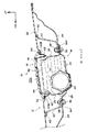
図1において、本実施の形態に係る車両用フードエアバッグ装置のフードへの組付け構造は、車両における例えばフロント側のフード12への車両用フードエアバッグ装置10の組付け構造に係り、該車両用フードエアバッグ装置10は、エアバッグモジュール14と、ドア18とを有している。
[First Embodiment]
In FIG. 1, the assembly structure of the vehicle hood airbag apparatus according to the present embodiment to the hood relates to the assembly structure of the vehicle
図1から図3において、エアバッグモジュール14は、インフレータ26からのガスの供給を受けて膨張展開するエアバッグ袋体16を有し、フード12におけるフードアウタパネル22とフードインナパネル24との間に該フードインナパネル24側から挿入され、該フードインナパネル24とフードアウタパネル22とを連結して補強するリインフォースメント40及びフードインナパネル24に対して組み付けられている。エアバッグ袋体16及びインフレータ26は、共にモジュールケース28内に収納されており、エアバッグ袋体16はインフレータ26からのガスの供給を受けてフードアウタパネル22の開口部22Aを通じてフード12外へ膨張展開するように構成されている。
In FIG. 1 to FIG. 3, the
モジュールケース28は、フードアウタパネル22の開口部22Aに対応して開口すると共に、車幅方向に長尺に形成された箱状部材であり、具体的には、車両前側の壁部材30と、車両後側の壁部材32と、底部部材34とを例えば溶接することで箱形状に形成されている。底部部材34には、壁部材30より車両前方及び壁部材32より後方に夫々延長されたフランジ部34Fが設けられている。即ちエアバッグモジュール14は、モジュールケース28のフランジ部34Fの部分において、ボルト36及びナット38を用いてフードインナパネル24に取り付けられ、リインフォースメント40と共締めされている。
The
リインフォースメント40は、例えば断面逆ハット形に形成され、フードアウタパネル22とフードインナパネル24との間に車幅方向に延設されている。またリインフォースメント40は、フードインナパネル24に対して直接的に結合されており、例えばマスチック42を介してフードアウタパネル22を支持するように構成されている。
The
インフレータ26は、モジュールケース28内に収納され、図示しない衝突体が車両の前部に衝突した際に、エアバッグ袋体16に対して膨張用のガスを供給するためのガス供給源であって、例えば、取付けブラケット44を用いることでモジュールケース28の車両前側の壁部材30寄りの底部部材34に固定されている。
The inflator 26 is housed in the
図3に示されるように、フードインナパネル24及びリインフォースメント40には、フードアウタパネル22の開口部22Aの車両前後方向の開口幅よりも大きく開口したエアバッグモジュール組付け用の挿入口70が形成されている。
As shown in FIG. 3, the hood
ドア18は、エアバッグモジュール14に対応してフードアウタパネル22に形成された開口部22Aを覆うと共に、エアバッグ袋体16の膨張時にその膨張力により展開して該開口部22Aを開放するように、該開口部22Aの周縁22Bに係止される蓋体であって、例えばアルミニウムや鉄の鋼板を成形したドアフレーム46の上から、合成樹脂製のカバー48を固着して構成され、図2に示されるように、フードアウタパネル22の開口部22Aの周縁22Bに、弾性変形することでフードアウタパネルから離脱可能な複数個のクリップ62により係止され、開口部22Aを覆う位置に保持されている。カバー48と周縁22Bとの間にはシール部材50が配設されている。クリップ62は、例えばドアフレーム46に固着されており、エアバッグ袋体16の膨張力がドア18に作用した際に弾性変形して、周縁22Bから離脱するようになっている。
The
図1,図3において、ヒンジ21は、フードインナパネル24に対して所定範囲内で相対変位可能となるように、該フードインナパネル24側の連結部材の一例たる段付きボルト52に連結され、ドア18の展開時に該ドア18を支持する部材であって、ドア18におけるドアフレーム46の後端側に、例えば該ドア18の長さ方向に沿って複数箇所設けられている。ヒンジ21のうち、段付きボルト52に連結される先端部21Bは、補強部材58により補強され、かつ先端部21B及び補強部材58には、段付きボルト52のスパン52Aが隙間をもって挿通される貫通穴60が形成されている。
1 and 3, the
段付きボルト52は、リインフォースメント40に固着された取付けブラケット54に、ナット56を用いて締結されており、ヒンジ21の車両上下方向及び車両前後方向への相対変位を所定範囲内で許容するスパン52Aを有している。
The stepped
ヒンジ21の先端部21Bに設けられた貫通穴60の形状は、少なくともヒンジ21の車両上下方向の相対変位を許容するように、例えば段付きボルト52の軸方向と直角方向、即ち略車両上下方向に長い長穴として形成されている。この貫通穴60の長さを大きく設定すると、先端部21Bとスパン52Aとの間の隙間が大きくなり、段付きボルト52におけるヒンジ21の車両上下方向の相対変位可能範囲を拡大させることができる。従って、貫通穴60の形状設定により、段付きボルト52におけるヒンジ21の車両上下方向の相対変位可能範囲内において、クリップ62をフードアウタパネル22から離脱させることも可能である。なお、貫通穴60の形状は、これに限られるものではなく、例えば車幅方向の相対変位を許容するように、貫通穴60の車幅方向径をより大きく設定してもよい。
The shape of the through
またヒンジ21は、例えばドア18のドアフレーム46の後端側に一体的に設けられ、ドア18の展開に伴って塑性変形し易いように該ドア18のドアフレーム46より低剛性に構成されている。更にヒンジ21は、余長部として構成された変形ストローク確保用の変形可能部21Aを有している。変形可能部21Aは、ヒンジ21の低剛性部分を折曲げて余長部としたものであり、ドア18の展開に伴って伸長するようになっている。なお、変形可能部21Aの折曲げ形状や余長量は、図示のものに限られない。
Further, the
(作用)
本実施形態は、上記のように構成されており、以下その作用について説明する。まず、フード12に対するドア18の組付けについて説明すると、図3において、ドアフレーム46にカバー48を固着すると共に、ヒンジ21の先端部21Bに補強部材58を固着してドア18としておき、該ドア18をフードアウタパネル22の上側から該フードアウタパネル22に嵌め込んで、クリップ62を開口部22Aの周縁22Bに係合させる(図2)。そして、図1,図3に示されるように、ヒンジ21の先端部21Bの貫通穴60に段付きボルト52を通し、該段付きボルト52を取付けブラケット54に固着されているナット56に締結することで、フードインナパネル24側に組み付ける。ドア18自体は軽い部品であるので、フード12に対する組付け作業性は良好である。
(Function)
This embodiment is configured as described above, and the operation thereof will be described below. First, the assembly of the
このとき、ドア18のヒンジ21は、段付きボルト52にフローティング状態で連結され、フードインナパネル24に対して所定範囲内、即ちスパン52Aと貫通穴60との間の隙間の範囲内、及びスパン52Aの長さの範囲内で相対変位可能となっているので、ドア18の位置を微調整することができ、ドア18の組付け時における開口部22Aと該ドア18との間の寸法のばらつきを、ヒンジ21が段付きボルト52に対して相対変位することで吸収することができる。
At this time, the
またドア18は、エアバッグモジュール14に対してはサブアッセンブリされないので、該サブアッセンブリ時の寸法ばらつきについては考慮する必要がない。このため、フードアウタパネル22の開口部22Aと該開口部22Aに設けられるドア18との意匠性を良好に維持して車両の外観品質を向上させることが可能である。また、ドア18をエアバッグモジュール14と分離しているので、エアバッグモジュール14にドア18が組み付けられている場合と比較して、上下振動によるドア18の車両上下方向の動き量を少なくできるので、該上下振動対策としてのフローティング量を抑制することが可能である。
Further, since the
次に、図3において、フード12に対するエアバッグモジュール14の組付けについて説明すると、モジュールケース28内にインフレータ26及びエアバッグ袋体16を収納して予めサブアッセンブリ化したエアバッグモジュール14を、エアバッグモジュール組付け用の挿入口70からフード12内に挿入し、フランジ部34Fをフードインナパネル24に当接させ、ボルト36をフードインナパネル24及びリインフォースメント40に通し、ナット38に対して締結すると、エアバッグモジュール14の組付けが完了する。
Next, the assembly of the
挿入口70とフードアウタパネル22の開口部22Aの車両前後方向の開口幅については、挿入口70の方が大きく設定されているので、エアバッグモジュール14の組付け作業性が向上するだけでなく、エアバッグモジュール14の前後寸法を大きく設定し、高さ寸法を相対的に小さく設定することが可能である。これにより、フードアウタパネル22の開口部22Aの車両前後方向の開口幅を、意匠性の観点から狭く設定しつつ、エアバッグモジュール14の高さ寸法を小さく設定できるので、車両への搭載性を向上させることが可能である。例えば、フード12が設けられるエンジンコンパートメント内の部品(図示せず)との位置関係により、フードアウタパネル22とフードインナパネル24の間の空間が制限される場合でも、該空間にエアバッグモジュール14を組み付けることが可能となる。なお、エアバッグモジュール14の前後寸法を大きく設定する場合には、エアバッグ16の膨張を考慮して、モジュールケース28の上部を、フードアウタパネル22の開口部22Aの開口幅と同等以下に絞り込むことが好ましい。
About the opening width of the
このように、車両用フードエアバッグ装置のフードへの組付け構造では、ドア18とエアバッグモジュール14とを別々に組み付けるようにしたので、エアバッグモジュール14及びドア18をフード12に組み付ける際の組付け作業性を大幅に向上させることができる。
As described above, in the assembly structure of the hood airbag apparatus for a vehicle to the hood , the
通常使用時においては、図2に示されるように、ドア18が複数個のクリップ62によりフードアウタパネル22の開口部22Aを覆う位置に保持されているので、開口部22Aはドア18により安定的に覆われた状態となっている。このため、通常使用時に開口部22Aとドアとの意匠性を良好に維持できる。
During normal use, as shown in FIG. 2, the
次に、衝突体が車両の前部に衝突した場合の作用について説明する。この場合、図1において、車両用フードエアバッグ装置10のインフレータ26が作動して、該インフレータ26から多量のガスがモジュールケース28内に折り畳み収納されているエアバッグ袋体16へ供給される。これによりエアバッグ袋体16が膨張し始めると、その膨張力によりドア18が開き、該エアバッグ袋体16がフード12の外へ膨張展開し、該エアバッグ袋体16に衝突体が当たることで、その衝撃が吸収される。
Next, an operation when the collision body collides with the front portion of the vehicle will be described. In this case, in FIG. 1, the
具体的には、図2において、エアバッグ袋体16の膨張時にその膨張力がドア18に作用し、該ドア18がエアバッグ袋体16の膨張力により押し上げられると、クリップ62が弾性変形してフードアウタパネル22から離脱し、ドア18が展開可能となる。このとき、ヒンジ21は、貫通穴60の下端が段付きボルト52に至るまで、該段付きボルト52に対して相対変位することができ、貫通穴60の下端が段付きボルト52に至ったところで先端部21Bが該段付きボルト52に係止される。ヒンジ21の先端部21Bは、補強部材58により補強されており、また段付きボルト52は、リインフォースメント40に対して配設されているので、段付きボルト52における先端部21Bの係止状態が安定している。
Specifically, in FIG. 2, when the
ヒンジ21の相対変位可能範囲の設定によっては、該相対変位可能範囲内においてクリップ62がフードアウタパネル22から離脱することができるので、ヒンジ21の存在がクリップ62の離脱の妨げになることを抑制でき、クリップ62をフードアウタパネル22から円滑に離脱させることができる。
Depending on the setting of the relative displaceable range of the
続いて、エアバッグ袋体16の膨張力によりドア18が押し上げられた際には、該ドア18よりも低剛性に構成されたヒンジ21が塑性変形することで該ドア18の展開が安定的に支持される。更に、余長部として構成された変形ストローク確保用の変形可能部21Aがドア18の展開に伴って伸長することで、例えばドア18が押し上げられて、すべてのクリップ62がフードアウタパネル22から離脱した後に、該ドア18がヒンジ21を中心としてフードアウタパネル22上へ反転するようにでき、安定したクリップ62の離脱を行うことで、ドア18を円滑に展開させることが可能である(展開状態については図示せず)。ドア18が展開することで、開口部22Aが開放され、該開口部22Aを通じてエアバッグ袋体16がフード12外へ膨張展開することが可能となる。
Subsequently, when the
なお、上記実施形態では、連結部材の一例として段付きボルト52を挙げたが、これに限られるものではなく、ヒンジ21をフローティング状態で連結できるものであれば、どのようなものを用いてもよい。また、ドアフレーム46の上からカバー48を固着することでドア18を構成するものとしたが、これに限られるものではなく、例えばカバー48を用いずに、ドアフレーム46自体がフードアウタパネル22の開口部22Aを覆うようにしてもよい。
In the above embodiment, the stepped
[第2実施形態]
図4において、本実施の形態に係る車両用フードエアバッグ装置のフードへの組付け構造は、車両における例えばフロント側のフード12への車両用フードエアバッグ装置20の組付け構造に係り、該車両用フードエアバッグ装置20は、エアバッグモジュール74と、ドア78とを有している。
[Second Embodiment]
In FIG. 4, the assembly structure of the vehicle hood airbag device according to the present embodiment to the hood relates to the assembly structure of the vehicle
エアバッグモジュール74は、インフレータ26からのガスの供給を受けて膨張展開するエアバッグ袋体16を有し、フード12におけるフードアウタパネル22とフードインナパネル24との間に該フードインナパネル24側から挿入され、該フードインナパネル24に対して組み付けられている。エアバッグ袋体16及びインフレータ26は、共にモジュールケース76内に収納されており、エアバッグ袋体16はインフレータ26からのガスの供給を受けてフードアウタパネル22の開口部22Aを通じてフード12外へ膨張展開するように構成されている。
The
モジュールケース76は、フードアウタパネル22の開口部22Aに対応して開口すると共に、車幅方向に長尺に形成された箱状部材であり、具体的には、略箱状に形成された底部部材84の車両前側に、上縁80Aにドア78の前縁78Aを係止するためのクリップ82が固着された壁部材80を、例えば溶接することで構成されている。底部部材84には、該底部部材84より車両前方及び後方にまで、具体的には挿入口70の車両前後方向の開口幅よりも車両前後方向に長く延びる取付けブラケット86が固着されている。即ちエアバッグモジュール74は、取付けブラケット86、ボルト36及びナット38を用いることでフードインナパネル24に取り付けられている。
The
インフレータ26の取付けブラケット44には、おねじ部88が設けられており、該おねじ部88は底部部材84及び壁部材80に挿通されている。該おねじ部88に対してナット90を締結することにより、インフレータ26がモジュールケース76に固定されると共に、底部部材84及び壁部材80が共締めされている。
The mounting
図5に示されるように、ドア78は、エアバッグモジュール74に予め組み付けられ、該エアバッグモジュール74に対応してフードアウタパネル22に形成された開口部22Aを覆うと共にエアバッグ袋体16の膨張時にその膨張力により展開して該開口部22Aを開放するように構成され、該開口部22Aの周縁22Bとの間にシール部材92を配設するためのシール面78Bを有している。具体的には、ドア78の後端部にはヒンジ96が設けられ、該ヒンジ96は底部部材84の後壁部84Eに例えばリベット94を用いて固定されている。ドア78の前縁78Aは、壁部材80の上縁80Aに設けられたクリップ82に係止されている。シール部材92は、ドア78とフードアウタパネル22との間の水密性を高めるための、例えばゴムシールである。
As shown in FIG. 5, the
ヒンジ96は、ドア78の展開に伴って塑性変形し易いように該ドア78より低剛性に構成され、かつ余長部として構成された変形ストローク確保用の変形可能部96Aを有している。変形可能部96Aは、ヒンジ96の低剛性部分を折曲げて余長部としたものであり、ドア78の展開に伴って伸長するようになっている。なお、変形可能部96Aの折曲げ形状や余長量は、図示のものに限られない。
The
図5に示されるように、エアバッグモジュール74がフード12に組み付けられる前の状態において、シール部材92は、フードアウタパネル22の開口部22Aの周縁22Bに設けられているが、これに限られず、エアバッグモジュール74側、即ちドア78のシール面78Bに設けてられていてもよい。
As shown in FIG. 5, in a state before the
なお、本実施形態では、エアバッグモジュール74を組み付けることで、フードアウタパネル22とフードインナパネル24とを連結して補強できるため、断面逆ハット形のリインフォースメントを配設していないが、これに限られず、該リインフォースメントを追加してもよい。
In the present embodiment, since the hood
他の部分は、第1実施形態と同様であるので、同一の部分には図面に同一の符号を付し、説明を省略する。 Since other parts are the same as those in the first embodiment, the same parts are denoted by the same reference numerals in the drawings, and description thereof is omitted.
(作用)
本実施形態は、上記のように構成されており、以下その作用について説明する。図5において、フード12に対するエアバッグモジュール74の組付けについて説明すると、予めモジュールケース76内にインフレータ26及びエアバッグ袋体16を収納しドア78を組み付けてエアバッグモジュール74をサブアッセンブリ化しておく。このエアバッグモジュール74をエアバッグモジュール組付け用の挿入口70からフード12内に挿入し、取付けブラケット86をフードインナパネル24に当接させる。そして、ボルト36をフードインナパネル24に通し、ナット38に対して締結すると、ドア78が開口部22Aを覆うと共に、シール面78Bがシール部材92に当接して、エアバッグモジュール74の組付けが完了する。
(Function)
This embodiment is configured as described above, and the operation thereof will be described below. 5, the assembly of the
このように、車両用フードエアバッグ装置のフードへの組付け構造では、ドア78が予め組み付けられたエアバッグモジュール74を、フードインナパネル24側からフード12内に挿入して組み付けるようにしたので、組付け作業時におけるフードアウタパネル22の外面の傷付きを防止することができ、これによってフード12の意匠性を良好に維持して車両の外観品質を向上させることができる。また、開口部22Aの周縁22Bとドア78のシール面78Bとの間にシール部材92を配設することで、エアバッグモジュール74をフードインナパネル24側からフード12内に挿入する際における該ドア78の傷付きを防止することができる。
Thus, in the assembly structure of the vehicle hood airbag apparatus to the hood, the
次に、衝突体が車両の前部に衝突した場合の作用について説明する。この場合、図4において、車両用フードエアバッグ装置20のインフレータ26が作動して、該インフレータ26から多量のガスがモジュールケース76内に折り畳み収納されているエアバッグ袋体16へ供給される。これによりエアバッグ袋体16が膨張し始めると、その膨張力によりドア78が開き、該エアバッグ袋体16がフード12の外へ膨張展開し、該エアバッグ袋体16に衝突体が当たることで、その衝撃が吸収される。
Next, an operation when the collision body collides with the front portion of the vehicle will be described. In this case, in FIG. 4, the
具体的には、エアバッグ袋体16の膨張時にその膨張力がドア78に作用し、該ドア78がエアバッグ袋体16の膨張力により押し上げられると、ドア78の前縁78Aが塑性変形しながらクリップ82から離脱し、該ドア78が展開可能となる。ドア78が展開する際には、該ドア78よりも低剛性に構成されたヒンジ96が塑性変形することで該ドア78の展開が安定的に支持される。更に、余長部として構成された変形ストローク確保用の変形可能部96Aがドア78の展開に伴って伸長することで、ドア78の前縁78Aがクリップ62から離脱した後に、該ドア78がヒンジ96を中心としてフードアウタパネル22上へ反転することができる。このため、ドア78を円滑に展開させることが可能である(展開状態については図示せず)。ドア78が展開することで、開口部22Aが開放され、該開口部22Aを通じてエアバッグ袋体16がフード12外へ膨張展開することが可能となる。
Specifically, when the
10 車両用フードエアバッグ装置
12 フード
14 エアバッグモジュール
16 エアバッグ袋体
18 ドア
20 車両用フードエアバッグ装置
21 ヒンジ
21A 変形可能部
22 フードアウタパネル
22A 開口部
22B 周縁
24 フードインナパネル
26 インフレータ
40 リインフォースメント
52 段付きボルト(連結部材)
54 取付けブラケット(連結部材)
62 クリップ
70 挿入口
74 エアバッグモジュール
76 モジュールケース
78 ドア
78B シール面
92 シール部材
96 ヒンジ
96A 変形可能部
DESCRIPTION OF
54 Mounting bracket (connecting member)
62
Claims (5)
該エアバッグモジュールに対応して前記フードアウタパネルに形成された開口部を覆うと共に、前記エアバッグ袋体の膨張時にその膨張力により展開して該開口部を開放するように、前記フードアウタパネルの上側から該開口部の周縁に係止されたドアと、を有し、
前記フードインナパネル及び前記リインフォースメントに、前記フードアウタパネルの前記開口部の車両前後方向の開口幅よりも大きく開口した前記エアバッグモジュール組付け用の挿入口が形成されていることを特徴とする車両用フードエアバッグ装置のフードへの組付け構造。 An airbag bag body that is inflated and deployed upon receiving a gas supply from an inflator, is inserted from the hood inner panel side between the hood outer panel and the hood inner panel in the hood, and the hood inner panel and the hood outer panel an air bag module is assembled against the cross-sectional reverse hat-shaped reinforcement and the inner hood panel to reinforce by connecting,
Together correspond to the airbag module cover the opening formed on the hood outer panel, so as to open the opening to expand by its expansion force upon inflation of the air bag body, an upper side of the hood outer panel And a door locked to the periphery of the opening ,
The vehicle hood inner panel and the reinforcement are formed with an insertion opening for assembling the airbag module that is wider than an opening width in the vehicle front-rear direction of the opening of the hood outer panel. Assembly structure for hood air bag device.
該ヒンジは、前記ドアの展開に伴って塑性変形し易いように該ドアより低剛性に構成され、かつ余長部として構成された変形ストローク確保用の変形可能部を有しており、前記リインフォースメントに対して配設された連結部材に、該リインフォースメントに対して所定範囲内で相対変位可能となるようにフローティング状態で連結されていることを特徴とする請求項1に記載の車両用フードエアバッグ装置のフードへの組付け構造。 Having a hinge for supporting the door when the door is deployed;
The hinge has a deformable portion for securing a deformation stroke, which is configured to be less rigid than the door so as to be easily plastically deformed as the door is expanded, and is configured as an extra length portion. 2. The vehicle hood according to claim 1, wherein the vehicle hood is connected in a floating state to a connection member arranged with respect to the reinforcement so as to be relatively displaceable within a predetermined range with respect to the reinforcement. Assembly structure of the airbag device to the hood .
該エアバッグモジュールに予め組み付けられ、該エアバッグモジュールに対応して前記フードアウタパネルに形成された開口部を覆うと共に前記エアバッグ袋体の膨張時にその膨張力により展開して該開口部を開放するように構成され、該開口部の周縁との間にシール部材を配設するためのシール面を有するドアと、を有し、
前記フードインナパネルに、前記フードアウタパネルの前記開口部の車両前後方向の開口幅よりも大きく開口した前記エアバッグモジュール組付け用の挿入口が形成されていることを特徴とする車両用フードエアバッグ装置のフードへの組付け構造。 It has an airbag bag body that inflates and deploys in response to the supply of gas from the inflator, and is inserted from the hood inner panel side between the hood outer panel and the hood inner panel in the hood, and assembled to the hood inner panel. An airbag module,
The air bag module is pre-assembled to cover the opening formed in the hood outer panel corresponding to the air bag module, and when the air bag body is inflated, the air bag is expanded by its inflating force to open the opening. And a door having a seal surface for disposing a seal member between the periphery of the opening , and
A hood airbag for a vehicle, wherein the hood inner panel is formed with an insertion opening for assembling the airbag module that is wider than an opening width in the vehicle front-rear direction of the opening of the hood outer panel. Assembly structure of the device to the hood .
該ヒンジは、前記ドアの展開に伴って塑性変形し易いように該ドアより低剛性に構成され、かつ余長部として構成された変形ストローク確保用の変形可能部を有して前記エアバッグモジュールに連結されていることを特徴とする請求項3に記載の車両用フードエアバッグ装置のフードへの組付け構造。 Having a hinge for supporting the door when the door is deployed;
The hinge module has a deformable portion for securing a deformation stroke, which is configured to be less rigid than the door so as to be easily plastically deformed with the deployment of the door, and is configured as an extra length portion. The structure for assembling the hood airbag device for a vehicle according to claim 3 to the hood .
前記エアバッグモジュールは、前記リインフォースメント及び前記フードインナパネルに対して組み付けられていることを特徴とする請求項3又は請求項4に記載の車両用フードエアバッグ装置のフードへの組付け構造。 Reinforcement with a cross-section reverse hat shape that connects and reinforces the hood inner panel and the hood outer panel,
The said airbag module is assembled | attached with respect to the said reinforcement and the said food inner panel, The assembly | attachment structure to the hood of the hood airbag apparatus for vehicles of Claim 3 or Claim 4 characterized by the above-mentioned.
Priority Applications (6)
| Application Number | Priority Date | Filing Date | Title |
|---|---|---|---|
| JP2006016596A JP4134328B2 (en) | 2006-01-25 | 2006-01-25 | Assembly structure of a vehicle hood airbag device to a hood |
| US12/160,238 US7913794B2 (en) | 2006-01-25 | 2007-01-04 | Hood airbag device for use in a vehicle |
| CN2007800031826A CN101374698B (en) | 2006-01-25 | 2007-01-04 | Hood airbag device for use in a vehicle |
| KR1020087018133A KR101027490B1 (en) | 2006-01-25 | 2007-01-04 | Hood airbag device for use in a vehicle |
| EP07700442A EP1976733B1 (en) | 2006-01-25 | 2007-01-04 | Hood airbag device for use in a vehicle |
| PCT/IB2007/000011 WO2007085918A1 (en) | 2006-01-25 | 2007-01-04 | Hood airbag device for use in a vehicle |
Applications Claiming Priority (1)
| Application Number | Priority Date | Filing Date | Title |
|---|---|---|---|
| JP2006016596A JP4134328B2 (en) | 2006-01-25 | 2006-01-25 | Assembly structure of a vehicle hood airbag device to a hood |
Publications (2)
| Publication Number | Publication Date |
|---|---|
| JP2007196798A JP2007196798A (en) | 2007-08-09 |
| JP4134328B2 true JP4134328B2 (en) | 2008-08-20 |
Family
ID=38002063
Family Applications (1)
| Application Number | Title | Priority Date | Filing Date |
|---|---|---|---|
| JP2006016596A Expired - Fee Related JP4134328B2 (en) | 2006-01-25 | 2006-01-25 | Assembly structure of a vehicle hood airbag device to a hood |
Country Status (6)
| Country | Link |
|---|---|
| US (1) | US7913794B2 (en) |
| EP (1) | EP1976733B1 (en) |
| JP (1) | JP4134328B2 (en) |
| KR (1) | KR101027490B1 (en) |
| CN (1) | CN101374698B (en) |
| WO (1) | WO2007085918A1 (en) |
Families Citing this family (13)
| Publication number | Priority date | Publication date | Assignee | Title |
|---|---|---|---|---|
| JP5029643B2 (en) * | 2009-03-31 | 2012-09-19 | 豊田合成株式会社 | Airbag device |
| DE102009023779A1 (en) * | 2009-06-03 | 2010-12-09 | GM Global Technology Operations, Inc., Detroit | Motor vehicle with windscreen airbag |
| EP2345564A1 (en) * | 2009-12-14 | 2011-07-20 | Ford Global Technologies, LLC | Airbag module |
| JPWO2011162122A1 (en) * | 2010-06-23 | 2013-08-19 | 本田技研工業株式会社 | Airbag device |
| DE102011085330A1 (en) | 2011-01-27 | 2012-08-02 | Takata-Petri Ag | Airbag arrangement for motor vehicle, has gas bag for protecting person located outside of vehicle along partial section of windscreen or other portion of exterior of motor vehicle |
| KR101198842B1 (en) * | 2011-05-23 | 2012-11-07 | 기아자동차주식회사 | External air bag module for vehicle and back beam for mounting external air bag module |
| DE102011088779B4 (en) | 2011-12-16 | 2021-12-23 | Bayerische Motoren Werke Aktiengesellschaft | Motor vehicle with an airbag |
| GB2516699B (en) * | 2013-07-30 | 2017-05-03 | Jaguar Land Rover Ltd | Airbag device for a vehicle bonnet |
| JP6406686B2 (en) * | 2014-02-19 | 2018-10-17 | 株式会社Subaru | Airbag device |
| US10246044B2 (en) * | 2016-02-12 | 2019-04-02 | Ford Global Technologies, Llc | Vehicle hood assembly with deployable pedestrian protection |
| JP7319958B2 (en) | 2017-07-28 | 2023-08-02 | ニューロ・インコーポレーテッド | Designing Adaptive Compartments for Autonomous and Semi-Autonomous Vehicles |
| US11731580B2 (en) | 2020-02-07 | 2023-08-22 | Nuro, Inc. | Methods and apparatus for activating multiple external airbags |
| WO2022051246A1 (en) * | 2020-09-03 | 2022-03-10 | Nuro, Inc. | Apparatus for implementing an external airbag |
Family Cites Families (15)
| Publication number | Priority date | Publication date | Assignee | Title |
|---|---|---|---|---|
| JP3245489B2 (en) | 1993-10-29 | 2002-01-15 | トヨタ自動車株式会社 | Waterproof structure of food airbag device |
| JPH0811662A (en) | 1994-06-27 | 1996-01-16 | Toyota Motor Corp | Lid mounting structure for air bag device |
| JP2003095044A (en) * | 2001-09-06 | 2003-04-03 | Takata Corp | External surface expanding air bag device |
| JP3791379B2 (en) | 2001-10-02 | 2006-06-28 | トヨタ自動車株式会社 | Hood airbag device |
| JP3975866B2 (en) * | 2002-08-30 | 2007-09-12 | 豊田合成株式会社 | Air bag device for pedestrian protection |
| JP4422454B2 (en) * | 2003-09-22 | 2010-02-24 | トヨタ自動車株式会社 | Vehicle hood structure |
| JP4269981B2 (en) | 2004-03-11 | 2009-05-27 | 豊田合成株式会社 | Pedestrian airbag device |
| JP4433845B2 (en) | 2004-03-23 | 2010-03-17 | 豊田合成株式会社 | Food panel |
| US7341274B2 (en) | 2004-03-17 | 2008-03-11 | Toyoda Gosei Co., Ltd. | Pedestrian airbag system |
| JP2005343198A (en) | 2004-05-31 | 2005-12-15 | Toyoda Gosei Co Ltd | Airbag device for pedestrian |
| JP4120673B2 (en) * | 2005-10-11 | 2008-07-16 | トヨタ自動車株式会社 | Airbag device for vehicle |
| JP4382740B2 (en) * | 2005-10-21 | 2009-12-16 | トヨタ自動車株式会社 | Hood airbag device |
| JP4187260B2 (en) * | 2006-01-25 | 2008-11-26 | トヨタ自動車株式会社 | Hood airbag device for vehicle |
| JP4113894B2 (en) * | 2006-01-25 | 2008-07-09 | トヨタ自動車株式会社 | Hood airbag device for vehicle |
| JP2007196789A (en) * | 2006-01-25 | 2007-08-09 | Takata Corp | Pedestrian protection airbag device |
-
2006
- 2006-01-25 JP JP2006016596A patent/JP4134328B2/en not_active Expired - Fee Related
-
2007
- 2007-01-04 CN CN2007800031826A patent/CN101374698B/en not_active Expired - Fee Related
- 2007-01-04 KR KR1020087018133A patent/KR101027490B1/en active IP Right Grant
- 2007-01-04 EP EP07700442A patent/EP1976733B1/en not_active Expired - Fee Related
- 2007-01-04 US US12/160,238 patent/US7913794B2/en not_active Expired - Fee Related
- 2007-01-04 WO PCT/IB2007/000011 patent/WO2007085918A1/en active Application Filing
Also Published As
| Publication number | Publication date |
|---|---|
| CN101374698A (en) | 2009-02-25 |
| JP2007196798A (en) | 2007-08-09 |
| KR20080080218A (en) | 2008-09-02 |
| KR101027490B1 (en) | 2011-04-06 |
| EP1976733A1 (en) | 2008-10-08 |
| US7913794B2 (en) | 2011-03-29 |
| WO2007085918A1 (en) | 2007-08-02 |
| US20090066069A1 (en) | 2009-03-12 |
| EP1976733B1 (en) | 2012-10-10 |
| CN101374698B (en) | 2011-06-08 |
Similar Documents
| Publication | Publication Date | Title |
|---|---|---|
| JP4134328B2 (en) | Assembly structure of a vehicle hood airbag device to a hood | |
| JP4113894B2 (en) | Hood airbag device for vehicle | |
| JP4382740B2 (en) | Hood airbag device | |
| US8128121B2 (en) | Steering column mounted knee airbag device | |
| US20100244416A1 (en) | Steering column mounted knee airbag device | |
| JP2007196789A (en) | Pedestrian protection airbag device | |
| JP2006205934A (en) | Air bag and non-occupant protection device | |
| JP4744278B2 (en) | Non-occupant protection device | |
| JP5044229B2 (en) | Airbag device | |
| JP4179302B2 (en) | Airbag device for vehicle | |
| JP4906700B2 (en) | Airbag device | |
| JP2005280556A (en) | Hood panel | |
| KR100836108B1 (en) | Headlining structure of air-bag module for vehicle | |
| JP4238755B2 (en) | Food panel | |
| JP4207823B2 (en) | Food panel | |
| JP4433470B2 (en) | Outside air bag apparatus | |
| JP2007168585A (en) | Vehicular hood air bag device | |
| JP4345579B2 (en) | Pedestrian airbag device | |
| JP5241646B2 (en) | Method for assembling airbag device | |
| JP2005343202A (en) | Airbag device for pedestrian | |
| JP4100428B2 (en) | Hood airbag device for vehicle | |
| JP2010208458A (en) | Knee airbag device attached to column | |
| JP2006096290A (en) | Airbag device for pedestrian | |
| JP2010228578A (en) | Mounting part structure of door mount airbag | |
| JP2005343203A (en) | Air bag device for pedestrian |
Legal Events
| Date | Code | Title | Description |
|---|---|---|---|
| A977 | Report on retrieval |
Free format text: JAPANESE INTERMEDIATE CODE: A971007 Effective date: 20071221 |
|
| A131 | Notification of reasons for refusal |
Free format text: JAPANESE INTERMEDIATE CODE: A131 Effective date: 20080108 |
|
| A521 | Request for written amendment filed |
Free format text: JAPANESE INTERMEDIATE CODE: A523 Effective date: 20080310 |
|
| TRDD | Decision of grant or rejection written | ||
| A01 | Written decision to grant a patent or to grant a registration (utility model) |
Free format text: JAPANESE INTERMEDIATE CODE: A01 Effective date: 20080415 |
|
| A01 | Written decision to grant a patent or to grant a registration (utility model) |
Free format text: JAPANESE INTERMEDIATE CODE: A01 |
|
| A711 | Notification of change in applicant |
Free format text: JAPANESE INTERMEDIATE CODE: A711 Effective date: 20080509 |
|
| A61 | First payment of annual fees (during grant procedure) |
Free format text: JAPANESE INTERMEDIATE CODE: A61 Effective date: 20080513 |
|
| A521 | Request for written amendment filed |
Free format text: JAPANESE INTERMEDIATE CODE: A821 Effective date: 20080509 |
|
| R151 | Written notification of patent or utility model registration |
Ref document number: 4134328 Country of ref document: JP Free format text: JAPANESE INTERMEDIATE CODE: R151 |
|
| FPAY | Renewal fee payment (event date is renewal date of database) |
Free format text: PAYMENT UNTIL: 20110613 Year of fee payment: 3 |
|
| FPAY | Renewal fee payment (event date is renewal date of database) |
Free format text: PAYMENT UNTIL: 20110613 Year of fee payment: 3 |
|
| S531 | Written request for registration of change of domicile |
Free format text: JAPANESE INTERMEDIATE CODE: R313531 |
|
| FPAY | Renewal fee payment (event date is renewal date of database) |
Free format text: PAYMENT UNTIL: 20110613 Year of fee payment: 3 |
|
| R350 | Written notification of registration of transfer |
Free format text: JAPANESE INTERMEDIATE CODE: R350 |
|
| FPAY | Renewal fee payment (event date is renewal date of database) |
Free format text: PAYMENT UNTIL: 20110613 Year of fee payment: 3 |
|
| FPAY | Renewal fee payment (event date is renewal date of database) |
Free format text: PAYMENT UNTIL: 20120613 Year of fee payment: 4 |
|
| R250 | Receipt of annual fees |
Free format text: JAPANESE INTERMEDIATE CODE: R250 |
|
| FPAY | Renewal fee payment (event date is renewal date of database) |
Free format text: PAYMENT UNTIL: 20120613 Year of fee payment: 4 |
|
| FPAY | Renewal fee payment (event date is renewal date of database) |
Free format text: PAYMENT UNTIL: 20130613 Year of fee payment: 5 |
|
| R250 | Receipt of annual fees |
Free format text: JAPANESE INTERMEDIATE CODE: R250 |
|
| R250 | Receipt of annual fees |
Free format text: JAPANESE INTERMEDIATE CODE: R250 |
|
| R250 | Receipt of annual fees |
Free format text: JAPANESE INTERMEDIATE CODE: R250 |
|
| R250 | Receipt of annual fees |
Free format text: JAPANESE INTERMEDIATE CODE: R250 |
|
| R250 | Receipt of annual fees |
Free format text: JAPANESE INTERMEDIATE CODE: R250 |
|
| R250 | Receipt of annual fees |
Free format text: JAPANESE INTERMEDIATE CODE: R250 |
|
| S111 | Request for change of ownership or part of ownership |
Free format text: JAPANESE INTERMEDIATE CODE: R313117 |
|
| R250 | Receipt of annual fees |
Free format text: JAPANESE INTERMEDIATE CODE: R250 |
|
| R350 | Written notification of registration of transfer |
Free format text: JAPANESE INTERMEDIATE CODE: R350 |
|
| R250 | Receipt of annual fees |
Free format text: JAPANESE INTERMEDIATE CODE: R250 |
|
| LAPS | Cancellation because of no payment of annual fees |