JP4132756B2 - Biochemical analyzer - Google Patents
Biochemical analyzer Download PDFInfo
- Publication number
- JP4132756B2 JP4132756B2 JP2001269280A JP2001269280A JP4132756B2 JP 4132756 B2 JP4132756 B2 JP 4132756B2 JP 2001269280 A JP2001269280 A JP 2001269280A JP 2001269280 A JP2001269280 A JP 2001269280A JP 4132756 B2 JP4132756 B2 JP 4132756B2
- Authority
- JP
- Japan
- Prior art keywords
- sample
- dry analytical
- spotting
- nozzle
- analytical element
- Prior art date
- Legal status (The legal status is an assumption and is not a legal conclusion. Google has not performed a legal analysis and makes no representation as to the accuracy of the status listed.)
- Expired - Fee Related
Links
Images


Landscapes
- Investigating Or Analysing Biological Materials (AREA)
- Automatic Analysis And Handling Materials Therefor (AREA)
- Apparatus Associated With Microorganisms And Enzymes (AREA)
Description
【0001】
【発明の属する技術分野】
本発明は、血液、尿等の検体を点着ノズルユニットにより比色タイプの乾式分析素子、電解質タイプの乾式分析素子などに点着し、検体中の所定の生化学物質の物質濃度、イオン活量等を求める生化学分析装置に関し、特に検体、乾式分析素子などを収容保持する機構に関するものである。
【0002】
【従来の技術】
従来より、検体の小滴を点着供給するだけでこの検体中に含まれている特定の化学成分または有形成分を定量分析することのできる比色タイプの乾式分析素子や検体に含まれる特定イオンのイオン活量を測定することのできる電解質タイプの乾式分析素子が開発され、実用化されている。これらの乾式分析素子を用いた生化学分析装置は、簡単かつ迅速に検体の分析を行うことができるので、医療機関、研究所等において好適に用いられている。
【0003】
比色タイプの乾式分析素子を使用する比色測定法は、検体を乾式分析素子に点着させた後、これをインキュベータ内で所定時間恒温保持して呈色反応(色素生成反応)させ、次いで検体中の所定の生化学物質と乾式分析素子に含まれる試薬との組み合わせにより予め選定された波長を含む測定用照射光をこの乾式分析素子に照射してその光学濃度を測定し、この光学濃度から、予め求めておいた光学濃度と所定の生化学物質の物質濃度との対応を表す検量線を用いて該生化学物質の濃度を求めるものである。
【0004】
一方、電解質タイプの乾式分析素子を使用する電位差測定法は、上記の光学濃度を測定する代わりに、同種の乾式イオン選択電極の2個1組からなる電極対に点着された検体中に含まれる特定イオンの活量を、参照液を用いてポテンシオメトリで定量分析することにより求めるものである。
【0005】
上記いずれの方法においても、液状の検体は検体容器(採血管等)に収容して装置にセットすると共に、その測定に必要な乾式分析素子を装置に供給し、検体容器から所定方向に移動が可能な点着ノズルを有する点着ノズルユニットを利用して、検体を吸引し点着位置に搬送された乾式分析素子に点着を行う。上記検体、乾式分析素子の装填、その他測定に必要な消耗品として多数のノズルチップ、希釈用の混合カップ、希釈液、参照液などを装置に装填する方法が種々提案されている(例えば、特開平8−43405号参照)。
【0006】
【発明が解決しようとする課題】
上記のような生化学分析装置においては、複数の検体を搭載して連続的に測定が行えるように設けることが、効率的にも、操作性の点でも好適であるが、そのために装置が大型化する問題がある。
【0007】
本発明はかかる点に鑑み、複数の検体とその測定項目に対応した乾式分析素子、ノズルチップ等の消耗品を搭載して効率よく測定が行える装置の小型化を図るようにした生化学分析装置を提供することを目的とする。
【0008】
【課題を解決するための手段】
本発明の生化学分析装置は、検体およびその測定に必要な乾式分析素子を搭載する円形のサンプラトレイと、該サンプラトレイに搭載した検体を吸引し乾式分析素子に点着する点着ノズルユニットと、検体が点着された乾式分析素子を恒温保持するインキュベータとを備えた生化学分析装置において、
前記サンプラトレイは円盤状の回転ディスクを備え、該回転ディスクに検体を収容した複数の検体容器、各検体の測定項目に対応する種類の複数の乾式分析素子、点着ノズルに装着するノズルチップ、希釈液を収容した希釈液容器、希釈用の混合カップを保持する各搭載部が配設され、
さらに、前記サンプラトレイは前記回転ディスクの中央部に非回転部を備え、該非回転部に参照液を収容した参照液容器を保持する参照液搭載部と、該参照液容器の開口部を開閉する蒸発防止蓋とを備えたことを特徴とするものである。
【0010】
前記サンプラトレイの内部には、前記乾式分析素子を前記回転ディスクの中心側から押し出して搬送する素子搬送部材を備え、さらに、前記回転ディスクには乾式分析素子の搭載部以外に、前記素子搬送部材の通過経路を備えたことを特徴とする。
【0011】
【発明の効果】
上記のような本発明によれば、サンプラトレイは円盤状の回転ディスクを備え、この回転ディスクに検体を収容した複数の検体容器、各検体の測定項目に対応する種類の乾式分析素子、点着ノズルに装着するノズルチップ、希釈液を収容した希釈液容器、希釈用の混合カップを搭載することにより、複数の検体とその測定項目に対応した乾式分析素子、ノズルチップ等の消耗品を搭載して効率よく測定が行え、オペレーターの作業負担が軽減できると共に、装置の小型化を図ることができる。
【0012】
前記サンプラトレイ中央の非回転部に参照液搭載部を設け、参照液容器の開口部を開閉する蒸発防止蓋を配設すると、この蒸発防止蓋の開閉を点着ノズルユニットの動作に連係して行う機構を簡易に構成することができる。
【0013】
【発明の実施の形態】
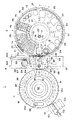
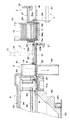
以下、本発明の実施の形態を図面に沿って説明する。図1は一例の生化学分析装置の概略機構を示す部分断面正面図、図2は生化学分析装置の点着ノズルユニットを除く要部機構の平面図、図3は乾式分析素子の搬送経路部分の断面正面図、図4は参照液搭載部分の断面図、図5は素子搬送機構の概略平面図、図6は検体容器搭載用の検体アダプタを示す分解斜視図である。
【0014】
生化学分析装置1は、サンプラトレイ2、点着部3、第1のインキュベータ4、第2のインキュベータ5、点着ノズルユニット6、素子搬送機構7、移送機構8、チップ廃却部9、素子廃却機構10などを備えてなる。
【0015】
サンプラトレイ2は円形で、検体を収容した検体容器11、未使用の乾式分析素子12(比色タイプの乾式分析素子および電解質タイプの乾式分析素子)を収容した素子カートリッジ13、消耗品(ノズルチップ14、希釈液容器15、混合カップ16および参照液容器17)を搭載する。なお、検体容器11は検体アダプタ18(図6参照)を介して搭載され、ノズルチップ14はチップラック19に多数収納されて搭載される。
【0016】
点着部3は、サンプラトレイ2の中心線の延長上に配置され、搬送された乾式分析素子12に血漿、全血、血清、尿などの検体の点着が行われるもので、点着ノズルユニット6によって比色測定タイプの乾式分析素子12には検体を、電解質タイプの乾式分析素子12には検体と参照液を点着する。この点着部3に続いてノズルチップ14が廃却されるチップ廃却部9が配置されている。
【0017】
第1のインキュベータ4は円形で、チップ廃却部9の延長位置に配置され、比色タイプの乾式分析素子12を収容して所定時間恒温保持し、比色測定を行う。第2のインキュベータ5(図2参照)は、点着部3の側方における隣接位置に配設され、電解質タイプの乾式分析素子12を収容して所定時間恒温保持し、電位差測定を行う。
【0018】
素子搬送機構7(図5参照)は、前記サンプラトレイ2の内部に配設され、このサンプラトレイ2の中心と第1のインキュベータ4の中心とを結び、点着部3およびチップ廃却部9を通る直線状の素子搬送経路R(図2)に沿って、サンプラトレイ2から第1のインキュベータ4に乾式分析素子12を搬送する。移送機構8は点着部3を兼ねて設置され、点着部3から第2のインキュベータ5に、素子搬送経路Rと直交する方向に、電解質タイプの乾式分析素子12を移送する。
【0019】
点着ノズルユニット6は上部に配設され、点着ノズル75が前述の素子搬送経路Rと同一直線上を移動し、検体および参照液の点着、希釈液による検体の希釈混合を行う。点着ノズル75は、先端にノズルチップ14を装着し、該ノズルチップ14内に検体、参照液等を吸引し吐出するもので、その吸引吐出を行う不図示のシリンジ手段が付設され、使用後のノズルチップ14はチップ廃却部9で外されて落下廃却される。
【0020】
素子廃却機構10(図2参照)は第1のインキュベータ4に付設され、測定後の比色タイプの乾式分析素子12を第1のインキュベータ4の中心部に押し出して落下廃棄する。なお、上記素子搬送機構7によって廃却することもできる。また、第2のインキュベータ5で測定した後の電解質タイプの乾式分析素子12は、前記移送機構8によって廃却穴69に廃棄される。
【0021】
また、サンプラトレイ2の近傍には、血液から血漿を分離する不図示の血液濾過ユニットが設置されている。
【0022】
次に、各部の構造を具体的に説明する。まず、前記サンプラトレイ2は、正転方向および逆転方向に回転駆動される円盤状の回転ディスク21と、その中央部の円盤状の非回転部22とを有する。
【0023】
回転ディスク21には、図2に示すように、各検体を収容した採血管等の検体容器11を検体アダプタ18を介して保持するA〜Eの5つの検体搭載部23と、これに隣接して各検体の測定項目に対応して通常複数の種類が必要とされる未使用の乾式分析素子12を積み重ねた状態で収容した素子カートリッジ13を保持する5つの素子搭載部24と、多数のノズルチップ14を保持孔に並んで収容したチップラック19を保持する2つのチップ搭載部25と、希釈液を収容した3つの希釈液容器15を保持する希釈液搭載部26と、希釈液と検体とを混合するための混合カップ16(多数のカップ状凹部が配置された成形品)を保持するカップ搭載部27とが円弧状に配置されている。
【0024】
また、非回転部22には、素子搬送経路Rの延長線上で点着ノズル75の移動範囲に、参照液を収容した参照液容器17を保持する筒状の参照液搭載部28を備え、この参照液搭載部28には、参照液容器17の開口部を開閉する蒸発防止蓋35(図4参照)が設置されている。
【0025】
前記回転ディスク21は、外周部の3カ所が支持ローラ31で支持され、中心部が支持軸32(図4参照)の外周に回転自在に保持されている。また、回転ディスク21の外周には、不図示のタイミングベルトが巻き掛けられ、駆動モータによって正転方向または逆転方向に回転駆動される。上記支持軸32は下端部が支持フレーム33に固定保持され、この支持軸32の上端部に円盤状の非回転部22の中心部が回転不能に取り付けられている。
【0026】
蒸発防止蓋35は、図4に示すように、参照液容器17の開口に圧接される蓋部材36が配設された揺動部材37を備え、この揺動部材37の下端がピン38によって非回転部22に揺動可能に枢支され、捩りバネ39によって閉方向に付勢されている。この蒸発防止蓋35は点着ノズルユニット6の移動に連係して開閉作動されるもので、揺動部材37の上端部に突出形成された係止部37aが、点着ノズルユニット6の移動フレーム72の下端角部72aと当接可能である。
【0027】
そして、点着ノズル75によって参照液を吸引するために、点着ノズルユニット6の移動フレーム72が参照液搭載部28上に移動した際には、その下端角部72aが蒸発防止蓋35の係止部37aに当接し、揺動部材37が鎖線で示すように開方向に揺動され、蓋部材36が上方に移動して参照液容器17を開口し、点着ノズル75によって参照液が吸引可能となる。移動フレーム72が点着部3の方向に移動した際には、捩りバネ39によって揺動部材37が閉方向に揺動し、蓋部材36が参照液容器17の開口部を閉塞して参照液の蒸発を防止し、その濃度変化による測定精度の低下を阻止する。
【0028】
素子搬送機構7は、サンプラトレイ2の内部における前記支持フレーム33に設置されている。この素子搬送機構7は、図5に示すように、サンプラトレイ2の半径方向に第1のインキュベータ4の中心位置に向けてスライド移動可能に配設された素子搬送部材41(搬送バー)を備え、この素子搬送部材41の前進移動制御によってその先端部で素子搭載部24の素子カートリッジ13から乾式分析素子12を押し出して点着部3に搬送し、点着後の乾式分析素子12を第1のインキュベータ4に搬送するように搬送距離が設定されている。
【0029】
また、前記サンプラトレイ2の回転ディスク21には、素子搭載部24以外に、例えばカップ搭載部27の下方位置に挿通孔29(図2参照)が開口され、素子搬送部材41の通過経路が設けられ、乾式分析素子12の詰まりなどが発生した際などの必要時に、乾式分析素子12の搬送を伴わない素子搬送部材41の前進移動が行えるようになっている。
【0030】
素子搬送部材41の後端部には、下方からスライダ43が固定され、このスライダ43は、支持フレーム33に素子搬送経路Rと平行に設置されたガイドロッド44に摺動自在に支持されると共に、支持フレーム33の前後に配設されたガイドプーリー45、搬送モータ49にて駆動される駆動プーリー46およびテンションプーリー47に巻き掛けられたベルト48の一部が固着されている。そして、搬送モータ49によって駆動プーリー46が回転駆動され、スライダ43の移動に伴って素子搬送部材41が前後方向に移動操作される。また、後退移動した素子搬送部材41は、後部がガイド部材42によって位置規制され、先端部は縦板34のガイド穴34a(図3参照)に挿入され、このガイド穴34aを摺動する。
【0031】
前記素子カートリッジ13は、図3に示すように、上部および側部が開放した箱状に設けられ、上方から未使用の乾式分析素子12が混在状態で通常複数枚重ねられて保持される。サンプラトレイ2の素子搭載部24に装填された素子カートリッジ13は、素子搭載部24の底壁24aに保持され、搬送面と同一高さに最下端部の乾式分析素子12が位置し、最下端部の前面側には1枚の乾式分析素子12のみが通過し得る開口13aが形成され、後面側には素子搬送部材41が挿通可能な開口13bが形成されている。
【0032】
また、図6に示すように、検体容器11をサンプラトレイ2に搭載する際に使用する検体アダプタ18は、筒状に形成され、上部から検体容器11が挿入される。外周にはフランジ部18aが形成されてサンプラトレイ2の検体搭載部23の穴に挿入された際にフランジ部18aが回転ディスク21の上面に係止して保持される。フランジ部18aより下方の筒部の前面には凸部18bが形成されて挿入方向が規制される。凸部18bの下部前面には4つの穴による識別部18cを有し、この識別部18cの穴に識別ピン18dを検体の種類(処理情報)、検体容器11の種類(サイズ)等に応じて選択的に装着し、分析の初期時点でサンプラトレイ2の外周部に配設された識別センサ30(図2)によってその識別が読み取られ、検体の希釈の有無、血漿濾過の有無などが判別されると共に、検体容器11のサイズに伴う液面変動量が算出され、それに応じた処理制御が行われる。
【0033】
上記アダプタ18の内底部には高さ調整部材51が挿入され、検体容器11の長さに応じて底部高さが調整可能である。血漿濾過が必要な検体容器11に対しては、アダプタ18に検体容器11を挿入した上に、濾過フィルターを備えたホルダー52がスペーサ53を介して装着される。
【0034】
上記のような検体容器11および素子カートリッジ13は任意に回転ディスク21のA〜Eの搭載部23,24に装填でき、測定前の入れ替えも可能で、緊急割り込みの検体を直ちに測定可能となっている。
【0035】
ここで、素子カートリッジ13に装填される乾式分析素子12について説明する。検体の呈色度合を測定するために使用される比色タイプの乾式分析素子12は矩形状のマウント内に試薬層が配設されてなり、マウントの中央に点着孔が形成され、点着孔に検体が点着される。検体のイオン活性を測定するために使用される電解質タイプの乾式分析素子12は、2箇所の液供給孔が形成されている。一方の液供給孔には検体が点着され、他方の液供給孔にはイオン活量が既知である参照液が点着される。また、イオン活量を測定するために電位差測定手段の電位測定用プローブと電気的に接続される3対のイオン選択電極対が形成されている。両乾式分析素子12の裏面には検査項目などを特定するための情報が記録された不図示のバーコードが付設されている。
【0036】
点着部3および移送機構8は、図2および図3に示すように、サンプラトレイ2と第1のインキュベータ4との間に素子搬送経路Rと直交する方向に長い支持台61を備え、その上に移動可能に摺動枠62が設置されている。この摺動枠62には、点着用開口63a(図3)が形成された主素子押え63および補助素子押え64が隣接して一体に移動可能に装着されている。主素子押え63(補助素子押え64も同様)は、支持台61に面する底面に、前記素子移動経路Rに沿って乾式分析素子12が搬送される凹部63bを有し、乾式分析素子12は支持台61上を滑るように移動する。また、摺動枠62は、一端部がガイドバー65に案内され、他端部側の長溝62aにピン66が係合され、素子搬送経路Rと直交方向に移動可能である。そのラックギヤ62bには駆動ギヤ67が噛合し、該駆動ギヤ67が駆動モータ68によって駆動されて摺動枠62が移動制御される。
【0037】
上記支持台61には、点着部3(点着位置)の側方位置(摺動枠62の移動方向の前方)に、第2のインキュベータ5が設置されると共に、さらに側方には廃却穴69が開口されている。
【0038】
そして、図2の通常状態では摺動枠62の停止位置は、主素子押え63が点着部3に位置し、サンプラトレイ2より搬送された乾式分析素子12に対する点着が行われ、点着後の比色タイプの乾式分析素子12は素子搬送部材41によって押し出されて第1のインキュベータ4に移送される。電解質タイプの乾式分析素子12への点着が行われると、摺動枠62が移動されて点着後の乾式分析素子12は主素子押え63に保持されたまま支持台61上を滑るように第2のインキュベータ5に移送され、電位差測定が行われる。その際には、摺動枠62の補助素子押え64が点着部3(点着位置)に移動し、その後に搬送される比色タイプの乾式分析素子12に対する検体の点着および第1のインキュベータ4への搬送が可能である。第2のインキュベータ5での測定が完了すると、摺動枠62がさらに移動されて測定後の乾式分析素子12を廃却穴69に移送して落下廃却する。
【0039】
点着ノズルユニット6(図1)は、固定フレーム70の水平ガイドレール71に、横方向に水平移動可能に保持された移動フレーム72を備え、この移動フレーム72の中央に設けられた縦ガイドレール73の両側に上下移動可能に2つのノズル固定台74が保持されている。この2つのノズル固定台74に、それぞれ棒状の点着ノズル75の上端部が上下方向に取り付けられている。
【0040】
上記ノズル固定台74には上方に延びる連結軸76が固着され、この連結軸76の上部は駆動伝達部材77に挿通され、ノズル固定台74と駆動伝達部材77との間の連結軸76の外周には圧縮バネ80が縮装されている。これにより、ノズル固定台74は駆動伝達部材77と一体に上下移動可能であると共に、点着ノズル75の先端部にノズルチップ14を装着する際に、圧縮バネ80を圧縮してノズル固定台74に対して駆動伝達部材77が下降移動可能であり、ノズルチップ14の装着力を得るようになっている。
【0041】
上記駆動伝達部材77は、上下のプーリ78に張設されたベルト79に固定され、不図示のモーターによるベルト79の走行に応じて上下移動する。なお、ベルト79の外側部位には、バランスウェイト99が取り付けられ、非駆動時の点着ノズル75の下降移動が防止される。
【0042】
また、移動フレーム72は不図示のベルト駆動機構によって横方向に駆動され、2つのノズル固定台74は独自に上下移動するように、その横移動および上下移動が制御され、2つの点着ノズル75,75は、一体に横移動すると共に、独自に上下移動するようになっている。例えば、一方の点着ノズル75は検体用であり、他方の点着ノズル75は希釈液用および参照液用である。
【0043】
両点着ノズル75は棒状に形成され、内部に軸方向に延びるエア通路が設けられ、下端にはピペット状のノズルチップ14がシール状態で嵌合される。この点着ノズル75にはそれぞれ不図示のシリンジポンプ等に接続されたエアチューブが連結され、吸引・吐出圧が供給される。使用後のノズルチップ14はチップ廃却部9で外されて落下廃却される。
【0044】
チップ廃却部9は、素子搬送経路Rにおける点着部3に続く位置に、乾式分析素子12の搬送面を上下方向に交差して設けられ、上部材81および下部材82を備える。このチップ廃却部9における前記支持台61には、楕円形に開口された落下口83が形成されている。上部材81は支持台61の上面に固着され、落下口83の直上部位には係合切欠き84が設けられ、下部材82は支持台61の下面に落下口83の下方を囲むように筒状に形成され、落下するノズルチップ14をガイドするようになっている。
【0045】
そして、ノズルチップ14が装着されている点着ノズル75を、上部材81内に下降させてから横方向に移動させ、その係合切欠き84にノズルチップ14の上端を係合してから、点着ノズル75を上昇移動させてノズルチップ14を抜き取り、外れたノズルチップ14は落下口83を通して落下廃却される。
【0046】
次に、比色測定を行う第1のインキュベータ4は、図1〜図3に示すように、外周部に円環状の回転部材87を備え、この回転部材87は内周下部に固着された傾斜回転筒88が下部のベアリング89に支持されて回転自在である。回転部材87の上部に上位部材90が一体に回転可能に配設されている。上位部材90の底面は平坦であり、回転部材87の上面には円周上に所定間隔で複数(図1の場合13個)の凹部が形成されて両部材87,90間にスリット状空間による素子室91が形成され、この素子室91の底面の高さは搬送面の高さと同一に設けられている。また、傾斜回転筒88の内孔は測定後の乾式分析素子12の廃却孔92に形成され、素子室91の中心側部分が廃却孔92に連通し、素子室91の乾式分析素子12がそのまま中心側に移動されて落下廃却される。
【0047】
上位部材90には図示しない加熱手段が配設され、その温度調整によって素子室91内の乾式分析素子12を所定温度に恒温保持する。また上位部材90には素子室91に対応して乾式分析素子12のマウントを上から押えて検体の蒸発防止を行う押え部材93が配設されている。上位部材90の上面には保温カバー94が配設される一方、この第1のインキュベータ4は全体が遮光カバー95によって覆われる。
【0048】
さらに、回転部材87の乾式分析素子12を収納する各素子室91の底面中央には測光用の開口91aが形成され、この開口91aを通して図1に示す位置に配設された測光ヘッド96による乾式分析素子12の反射光学濃度の測定が行われる。なお、回転部材87の一部には、不図示の濃度基準板が設置されている。
【0049】
第1のインキュベータ4の回転駆動は、回転部材87を支持する傾斜回転筒88の外周部分に不図示のタイミングベルトが巻き掛けられ、このタイミングベルトが駆動モータの駆動プーリー(共に不図示)に対しても巻き掛けられ、駆動モータの正逆回転駆動によって回転部材87の往復回転駆動を行うように構成されている。そして、第1のインキュベータ4の回転操作は、所定回転位置の下方に配設された測光ヘッド96に対して、まず、白黒色の濃度基準板の濃度を検出して校正を行った後に、順次素子室91に挿入されている乾式分析素子12の呈色反応の光学濃度の測定を行い、この一連の測定の後、逆回転して基準位置に復帰し、次の測定を行うように、所定角度範囲内で往復回転駆動を行うように制御される。
【0050】
第1のインキュベータ4に付設された廃却機構10(図1)は、外周側から中心方向に素子室91内に進退移動する廃却バー101を備えている。この廃却バー101は後端部が水平方向に走行するベルト102に固定され、駆動モータ103の駆動によるベルト102の走行に応じ、素子室91から測定後の乾式分析素子12を押し出して廃却する。なお、廃却孔92の下方には測定後の乾式分析素子12を回収する回収箱が配設される。
【0051】
また、イオン活量を測定する第2のインキュベータ5は、前述の摺動枠62の主素子押え63が上位部材となり、その凹部63bによって測定本体97の上面との間に1つの素子室が形成される。この第2のインキュベータ5には、図示しない加熱手段が配設され、その温度調整によって乾式分析素子12のイオン活量を測定する部分を所定温度に恒温加熱する。さらに、測定本体97の側辺部にはイオン活量測定のための3対の電位測定用プローブ98が出没して乾式分析素子12のイオン選択電極に接触可能に設けられる。そして、一方の液供給孔に検体が、他方の液供給孔に参照液が点着された乾式分析素子12では、イオン選択電極対の間にそれぞれ参照液と検体との間のイオン活量の差に対応する電位差が発生するため、電位測定用プローブ98により各イオン選択電極対から生ずる電位差を測定すれば検体中の各イオン活量が測定できる。
【0052】
なお、不図示の血漿濾過ユニットは、サンプラトレイ2に保持された検体容器11(採血管)の内部に挿入され上端開口部に取り付けられたガラス繊維からなるフィルターを有する前記ホルダー52を介して血液から血漿を分離吸引し、ホルダー52上端のカップ部に濾過された血漿を保持するようになっている。
【0053】
次いで、本実施形態の動作について説明する。まず、分析を行う前に、サンプラトレイ2の各搭載部23〜28に、各検体を収容した検体容器11を識別部18cがセットされた検体アダプタ18を使用して搭載すると共に、その測定項目に対応した種類の乾式分析素子12を装填した各素子カートリッジ13を測定する検体容器11に対応する位置に搭載し、さらに、消耗品であるノズルチップ14を収容したチップラック19、混合カップ16、希釈液容器15および参照液容器17を搭載して、測定準備を行う。
【0054】
その後、分析処理をスタートする。初期時点で、サンプラトレイ2の回転ディスク21を1回転させ、識別センサ30によって検体アダプタ18の識別部18cの設定を読み取り、搭載された各検体の希釈の有無、血漿濾過の有無などを判別する。
【0055】
まず、血漿濾過が必要な検体の場合には、血液濾過ユニットにより、検体容器11内の全血を濾過して血漿成分を得る。次に、回転ディスク21を回転させて測定する検体の素子カートリッジ13(素子搭載部24)を点着部3に対応する位置に停止させる。素子搬送部材41によりその素子カートリッジ13から乾式分析素子12を点着部3に搬送する。その搬送途中に乾式分析素子12に設けられたバーコードが読み取られ、乾式分析素子12の検査項目などを検出する。読み取られた検査項目がイオン活量測定の場合、希釈依頼項目の場合等に応じて異なる処理を行う。
【0056】
読み取られた検査項目が比色測定の場合は、サンプラトレイ2を回転させて点着ノズル75の下方にノズルチップ14を移動させ、点着ノズル75に装着する。続いて検体容器11を移動させ、点着ノズル75を下降してノズルチップ14に検体を吸引し、点着ノズル75を点着部3に移動して、乾式分析素子12に検体を点着する。
【0057】
そして、検体が点着された比色タイプの乾式分析素子12が第1のインキュベータ4に挿入される。次に、第1のインキュベータ4の素子室91を回転して、挿入された乾式分析素子12を順次測光ヘッド96と対向する位置に移動する。そして、測光ヘッド96による乾式分析素子12の反射光学濃度の測定が行われる。測定終了後、測定済みの乾式分析素子12は中心側に押し出して廃却する。測定結果を出力し、使用済みのノズルチップ14をチップ廃却部9で点着ノズル75から外して下方に落下廃却し、処理を終了する。
【0058】
次いで、検査項目が希釈依頼項目の場合、例えば血液の濃度が濃すぎて正確な検査を行うことができないような場合には、サンプラトレイ2を移動してノズルチップ14を点着ノズル75に装着する。次にサンプラトレイ2を移動して検体上で点着ノズル75を下降してノズルチップ14に検体を吸引する。サンプラトレイ2を移動して吸引した検体をノズルチップ14から混合カップ16に分注した後、使用済みのノズルチップ14を外す。次いで、新しいノズルチップ14を点着ノズル75に装着し、希釈液容器15からノズルチップ14に希釈液を吸引する。吸引した希釈液をノズルチップ14から混合カップ16に吐出する。そして、ノズルチップ14を混合カップ16内に挿入して吸引と吐出とを繰り返して撹拌を行う。撹拌を行った後、希釈した検体をノズルチップ14に吸引し、その点着ノズル75を点着部3に移動して、乾式分析素子12に検体を点着する。以下同様に、測光、素子廃却、結果出力およびチップ廃却を行って処理を終了する。
【0059】
次いで、検査項目がイオン活量の測定の場合について説明する。なお、イオン活量の測定の場合は、電解質タイプの乾式分析素子12が搬送される。まず、一方の点着ノズル75にノズルチップ14を装着し、検体を吸引する。次に、他方の点着ノズル75にノズルチップ14を装着し、参照液容器17から参照液を吸引する。次いで、一方の点着ノズル75により検体を乾式分析素子12の一方の液供給孔に点着し、さらに、他方の点着ノズル75により参照液を乾式分析素子12の他方の液供給孔に点着する。
【0060】
そして、検体および参照液が点着された乾式分析素子12が、点着部3から摺動枠62の移動によって第2のインキュベータ5に移送される。この乾式分析素子12が第2のインキュベータ5に挿入されると、電位差測定用プローブ98によってイオン活量の測定が行われる。測定終了後、測定後の乾式分析素子12を摺動枠62の移動によって廃却穴69に移送して廃却する。そして測定結果を出力し、両方の使用済みのノズルチップ14を両点着ノズル75から外して廃却し、処理を終了する。
【0061】
なお、本実施の形態では、乾式分析素子12を素子カートリッジ13を使用し回転ディスク21に搭載したが、必ずしも必要とせず、乾式分析素子12を直接に回転ディスク21に搭載する構成とすることで適用が可能である。
【0062】
上記のような実施の形態では、サンプラトレイ2の回転ディスク21に、複数の検体容器11とその測定用の乾式分析素子12を収容した素子カートリッジ13およびノズルチップ14、希釈液容器15、混合カップ16の消耗品を、非回転部22に参照液容器17をそれぞれ搭載するようにしたことにより、複数種類の検体を必要な乾式分析素子12と組にして装填することができ、装填操作が間違いなく容易に行え、緊急検体にも対応でき、オペレータの作業が容易となり、効率の良い測定処理がコンパクトな装置構成を確保しつつ行える。
【図面の簡単な説明】
【図1】本発明の一つの実施の形態における生化学分析装置の概略構成を示す部分断面正面図、
【図2】生化学分析装置の点着ノズルユニットを除く要部機構の平面図
【図3】乾式分析素子の搬送経路部分の断面正面図
【図4】参照液搭載部分の断面図
【図5】素子搬送機構の概略平面図
【図6】検体容器搭載用の検体アダプタを示す分解斜視図
【符号の説明】
1 生化学分析装置
2 サンプラトレイ
3 点着部
4 第1のインキュベータ
5 第2のインキュベータ
6 点着ノズルユニット
7 素子搬送機構
8 移送機構
9 チップ廃却部
11 検体容器
12 乾式分析素子
13 素子カートリッジ
14 ノズルチップ
15 希釈液容器
16 混合カップ
17 参照液容器
19 チップラック
21 回転ディスク
22 非回転部
23〜28 搭載部
29 挿通孔(通過経路)
35 蒸発防止蓋
41 素子搬送部材
75 点着ノズル
R 素子搬送経路[0001]
BACKGROUND OF THE INVENTION
In the present invention, a specimen such as blood or urine is spotted on a colorimetric type dry analytical element, an electrolyte type dry analytical element or the like by a spotting nozzle unit, and the concentration and ion activity of a predetermined biochemical substance in the specimen. More particularly, the present invention relates to a mechanism for accommodating and holding specimens, dry analytical elements, and the like.
[0002]
[Prior art]
Conventionally, a specific color component of a dry analytical element or sample that can quantitatively analyze a specific chemical component or formed component contained in this sample simply by spotting and supplying a small droplet of the sample An electrolyte type dry analytical element capable of measuring ion activity of ions has been developed and put into practical use. Biochemical analyzers using these dry analytical elements are suitable for use in medical institutions, laboratories and the like because they can easily and quickly analyze samples.
[0003]
In the colorimetric measurement method using a colorimetric type dry analytical element, after a sample is spotted on the dry analytical element, it is held at a constant temperature in an incubator for a color reaction (dye generation reaction), and then This dry analytical element is irradiated with measurement irradiation light containing a wavelength selected in advance by a combination of a predetermined biochemical substance in the sample and a reagent contained in the dry analytical element, and the optical density is measured. Thus, the concentration of the biochemical substance is obtained using a calibration curve representing the correspondence between the optical density obtained in advance and the substance concentration of the predetermined biochemical substance.
[0004]
On the other hand, the potential difference measurement method using an electrolyte type dry analytical element is included in a sample spotted on an electrode pair consisting of two pairs of the same kind of dry ion selective electrodes instead of measuring the above optical density. The activity of specific ions is determined by quantitative analysis with potentiometry using a reference solution.
[0005]
In any of the above methods, a liquid sample is accommodated in a sample container (such as a blood collection tube) and set in the apparatus, and a dry analytical element necessary for the measurement is supplied to the apparatus and moved in a predetermined direction from the sample container. Using a spotting nozzle unit having a possible spotting nozzle, the sample is sucked and spotted on the dry analytical element transported to the spotting position. Various methods have been proposed for loading the above-mentioned specimens, dry analytical elements, and other nozzle chips, diluting mixing cups, diluting liquids, reference liquids and the like as consumables necessary for measurement. (For example, see JP-A-8-43405) .
[0006]
[Problems to be solved by the invention]
In the biochemical analysis apparatus as described above, it is preferable to mount a plurality of specimens so that continuous measurement can be performed, which is preferable in terms of efficiency and operability. There is a problem.
[0007]
In view of the above, the present invention is directed to downsizing of a device capable of efficiently performing measurement by mounting consumables such as dry analysis elements and nozzle tips corresponding to a plurality of specimens and measurement items thereof. The purpose is to provide.
[0008]
[Means for Solving the Problems]
The biochemical analyzer of the present invention includes a circular sampler tray on which a sample and a dry analysis element necessary for the measurement are mounted, a spotting nozzle unit that sucks the sample mounted on the sampler tray and places it on the dry analysis element. In a biochemical analyzer equipped with an incubator that maintains a constant temperature of a dry analytical element on which a specimen is spotted,
The sampler tray includes a disk-shaped rotating disk, a plurality of sample containers containing samples on the rotating disk, a plurality of dry analysis elements of a type corresponding to the measurement item of each sample, a nozzle chip attached to a spotting nozzle, A diluent container containing a diluent, and each mounting portion for holding a mixing cup for dilution are arranged,
Further, the sampler tray has a non-rotating part at the center of the rotating disk, and opens and closes a reference liquid mounting part for holding a reference liquid container containing a reference liquid in the non-rotating part, and an opening part of the reference liquid container. With evaporation prevention lid It is characterized by this.
[0010]
The sampler tray includes an element conveying member that pushes and conveys the dry analytical element from the center side of the rotating disk, and the rotating disk has the element conveying member in addition to the dry analytical element mounting portion. It is characterized by having a passage route.
[0011]
【The invention's effect】
According to the present invention as described above, the sampler tray is provided with a disk-shaped rotating disk, a plurality of sample containers containing samples on the rotating disk, a dry analytical element of a type corresponding to the measurement item of each sample, and a spotting By mounting a nozzle tip to be mounted on the nozzle, a diluent container containing diluent, and a mixing cup for dilution, consumables such as multiple analytical samples and dry analysis elements corresponding to the measurement items, nozzle tips, etc. Measurement can be performed efficiently, the operator's workload can be reduced, and the device can be downsized.
[0012]
When a reference liquid mounting part is provided in the non-rotating part at the center of the sampler tray and an evaporation prevention lid for opening and closing the opening of the reference liquid container is provided, the opening and closing of the evaporation prevention lid is linked to the operation of the spotting nozzle unit. The mechanism to be performed can be configured easily.
[0013]
DETAILED DESCRIPTION OF THE INVENTION
Hereinafter, embodiments of the present invention will be described with reference to the drawings. FIG. 1 is a partial cross-sectional front view showing a schematic mechanism of an example biochemical analyzer, FIG. 2 is a plan view of a main mechanism excluding a spotting nozzle unit of the biochemical analyzer, and FIG. 3 is a transport path portion of a dry analytical element. FIG. 4 is a sectional view of a reference liquid mounting portion, FIG. 5 is a schematic plan view of an element transport mechanism, and FIG. 6 is an exploded perspective view showing a sample adapter for mounting a sample container.
[0014]
The
[0015]
The
[0016]
The
[0017]
The
[0018]
The element transport mechanism 7 (see FIG. 5) is disposed inside the
[0019]
The spotting
[0020]
The element discarding mechanism 10 (see FIG. 2) is attached to the
[0021]
Further, a blood filtration unit (not shown) that separates plasma from blood is installed in the vicinity of the
[0022]
Next, the structure of each part will be specifically described. First, the
[0023]
As shown in FIG. 2, the
[0024]
Further, the
[0025]
The
[0026]
As shown in FIG. 4, the
[0027]
When the moving
[0028]
The
[0029]
In addition to the
[0030]
A
[0031]
As shown in FIG. 3, the
[0032]
As shown in FIG. 6, the
[0033]
A
[0034]
The
[0035]
Here, the dry
[0036]
As shown in FIGS. 2 and 3, the
[0037]
The
[0038]
In the normal state of FIG. 2, the sliding
[0039]
The spotting nozzle unit 6 (FIG. 1) includes a moving
[0040]
A connecting
[0041]
The
[0042]
The moving
[0043]
Both the spotting
[0044]
The
[0045]
Then, the spotting
[0046]
Next, as shown in FIGS. 1 to 3, the
[0047]
The
[0048]
Further, an
[0049]
The rotational drive of the
[0050]
The disposal mechanism 10 (FIG. 1) attached to the
[0051]
Further, in the second incubator 5 for measuring the ion activity, the
[0052]
A plasma filtration unit (not shown) is inserted through the
[0053]
Next, the operation of this embodiment will be described. First, before performing the analysis, the
[0054]
Thereafter, the analysis process is started. At the initial time, the
[0055]
First, in the case of a specimen that requires plasma filtration, the whole blood in the
[0056]
When the read inspection item is colorimetric measurement, the
[0057]
Then, the colorimetric dry
[0058]
Next, when the inspection item is a dilution request item, for example, when the blood concentration is too high to perform an accurate inspection, the
[0059]
Next, the case where the inspection item is measurement of ion activity will be described. In the case of measuring the ion activity, the electrolyte type dry
[0060]
Then, the dry
[0061]
In the present embodiment, the
[0062]
In the embodiment as described above, the rotating
[Brief description of the drawings]
FIG. 1 is a partial cross-sectional front view showing a schematic configuration of a biochemical analyzer in one embodiment of the present invention;
FIG. 2 is a plan view of the main part mechanism of the biochemical analyzer excluding the spotting nozzle unit.
FIG. 3 is a cross-sectional front view of a transport path portion of a dry analytical element.
FIG. 4 is a cross-sectional view of a reference liquid mounting portion.
FIG. 5 is a schematic plan view of an element transport mechanism.
FIG. 6 is an exploded perspective view showing a sample adapter for mounting a sample container.
[Explanation of symbols]
1 Biochemical analyzer
2 Sampler tray
3 point landing
4 First incubator
5 Second incubator
6-point nozzle unit
7 Element transport mechanism
8 Transfer mechanism
9 Chip Disposal Department
11 Sample container
12 Dry analytical element
13 element cartridge
14 Nozzle tip
15 Diluent container
16 mixing cups
17 Reference solution container
19 tip rack
21 Rotating disc
22 Non-rotating part
23-28 mounted part
29 Insertion hole (passage route)
35 Evaporation prevention lid
41 Element conveying member
75 spot nozzle
R element transport path
Claims (3)
前記サンプラトレイは円盤状の回転ディスクを備え、該回転ディスクに検体を収容した複数の検体容器、各検体の測定項目に対応する種類の複数の乾式分析素子、点着ノズルに装着するノズルチップ、希釈液を収容した希釈液容器、希釈用の混合カップを保持する各搭載部が配設され、
さらに、前記サンプラトレイは前記回転ディスクの中央部に非回転部を備え、該非回転部に参照液を収容した参照液容器を保持する参照液搭載部と、該参照液容器の開口部を開閉する蒸発防止蓋とを備えたことを特徴とする生化学分析装置。A circular sampler tray that mounts the sample and the dry analytical element necessary for its measurement, a spotting nozzle unit that sucks the sample mounted on the sampler tray and places it on the dry analytical element, and a dry analysis in which the sample is spotted In a biochemical analyzer equipped with an incubator that keeps the element at a constant temperature,
The sampler tray includes a disk-shaped rotating disk, a plurality of sample containers containing samples on the rotating disk, a plurality of dry analysis elements of a type corresponding to the measurement item of each sample, a nozzle chip attached to a spotting nozzle, A diluent container containing a diluent, and each mounting portion for holding a mixing cup for dilution are arranged,
Further, the sampler tray has a non-rotating part at the center of the rotating disk, and opens and closes a reference liquid mounting part for holding a reference liquid container containing a reference liquid in the non-rotating part, and an opening part of the reference liquid container. A biochemical analyzer comprising an evaporation prevention lid .
Priority Applications (2)
| Application Number | Priority Date | Filing Date | Title |
|---|---|---|---|
| JP2001269280A JP4132756B2 (en) | 2001-09-05 | 2001-09-05 | Biochemical analyzer |
| US10/233,554 US7285245B2 (en) | 2001-09-05 | 2002-09-04 | Biochemical analysis method and apparatus |
Applications Claiming Priority (1)
| Application Number | Priority Date | Filing Date | Title |
|---|---|---|---|
| JP2001269280A JP4132756B2 (en) | 2001-09-05 | 2001-09-05 | Biochemical analyzer |
Publications (3)
| Publication Number | Publication Date |
|---|---|
| JP2003075453A JP2003075453A (en) | 2003-03-12 |
| JP2003075453A5 JP2003075453A5 (en) | 2006-04-06 |
| JP4132756B2 true JP4132756B2 (en) | 2008-08-13 |
Family
ID=19095129
Family Applications (1)
| Application Number | Title | Priority Date | Filing Date |
|---|---|---|---|
| JP2001269280A Expired - Fee Related JP4132756B2 (en) | 2001-09-05 | 2001-09-05 | Biochemical analyzer |
Country Status (1)
| Country | Link |
|---|---|
| JP (1) | JP4132756B2 (en) |
Families Citing this family (4)
| Publication number | Priority date | Publication date | Assignee | Title |
|---|---|---|---|---|
| JP5249988B2 (en) * | 2010-05-07 | 2013-07-31 | 株式会社日立ハイテクノロジーズ | Nucleic acid amplification apparatus and nucleic acid test apparatus using the same |
| CN104020309B (en) * | 2014-06-25 | 2015-12-30 | 长春迪瑞医疗科技股份有限公司 | The consumables pallet automatic loading device of Full-automatic chemiluminescence immunoassay analysis meter |
| CN104655865B (en) * | 2015-01-30 | 2017-04-26 | 重庆科斯迈生物科技有限公司 | Chemiluminescence immunoassay analyzer incubator |
| CN104634984B (en) * | 2015-02-10 | 2016-06-22 | 中国科学院苏州生物医学工程技术研究所 | A kind of full-automatic fluorescence immunoassay system |
-
2001
- 2001-09-05 JP JP2001269280A patent/JP4132756B2/en not_active Expired - Fee Related
Also Published As
| Publication number | Publication date |
|---|---|
| JP2003075453A (en) | 2003-03-12 |
Similar Documents
| Publication | Publication Date | Title |
|---|---|---|
| JP4132756B2 (en) | Biochemical analyzer | |
| JP2004239892A (en) | Automatic analysis device | |
| JP5634969B2 (en) | Biochemical analyzer and rotational conveyance method | |
| US20020031844A1 (en) | Biochemical analysis apparatus | |
| JP2002181834A (en) | Cartridge for biochemical analysis | |
| JP2003329695A (en) | Biochemical analyzer | |
| JP3850215B2 (en) | Biochemical analyzer | |
| JP3919107B2 (en) | Automatic analyzer | |
| JP3899370B2 (en) | Automatic analyzer | |
| JP4142278B2 (en) | Biochemical analyzer | |
| JP4475570B2 (en) | Centrifuge built-in analyzer | |
| JP2004219218A (en) | Automatic analyzer | |
| JP2005009868A (en) | Autoanalyzer | |
| JP4053222B2 (en) | Biochemical analyzer | |
| JP5587271B2 (en) | Interference prevention member separation device and biochemical analysis device | |
| JP3750772B2 (en) | Biochemical analyzer | |
| JP4094234B2 (en) | incubator | |
| JP3681885B2 (en) | Biochemical analyzer | |
| JP3853741B2 (en) | incubator | |
| JP2002207046A (en) | Incubator | |
| JP3682029B2 (en) | Biochemical analyzer | |
| JP2003075456A (en) | Spottedly sticking device for biochemical analyzer | |
| JP2002181832A (en) | Cartridge for biochemical analysis | |
| JP2003075452A (en) | Biochemical analyzer and specimen adaptor | |
| JPH11237386A (en) | Biochemical analyzer |
Legal Events
| Date | Code | Title | Description |
|---|---|---|---|
| A521 | Written amendment |
Free format text: JAPANESE INTERMEDIATE CODE: A523 Effective date: 20060215 |
|
| A621 | Written request for application examination |
Free format text: JAPANESE INTERMEDIATE CODE: A621 Effective date: 20060215 |
|
| A711 | Notification of change in applicant |
Free format text: JAPANESE INTERMEDIATE CODE: A712 Effective date: 20061204 |
|
| A977 | Report on retrieval |
Free format text: JAPANESE INTERMEDIATE CODE: A971007 Effective date: 20061207 |
|
| A131 | Notification of reasons for refusal |
Free format text: JAPANESE INTERMEDIATE CODE: A131 Effective date: 20080304 |
|
| A521 | Written amendment |
Free format text: JAPANESE INTERMEDIATE CODE: A523 Effective date: 20080501 |
|
| TRDD | Decision of grant or rejection written | ||
| A01 | Written decision to grant a patent or to grant a registration (utility model) |
Free format text: JAPANESE INTERMEDIATE CODE: A01 Effective date: 20080527 |
|
| A01 | Written decision to grant a patent or to grant a registration (utility model) |
Free format text: JAPANESE INTERMEDIATE CODE: A01 |
|
| A61 | First payment of annual fees (during grant procedure) |
Free format text: JAPANESE INTERMEDIATE CODE: A61 Effective date: 20080602 |
|
| FPAY | Renewal fee payment (event date is renewal date of database) |
Free format text: PAYMENT UNTIL: 20110606 Year of fee payment: 3 |
|
| R150 | Certificate of patent or registration of utility model |
Ref document number: 4132756 Country of ref document: JP Free format text: JAPANESE INTERMEDIATE CODE: R150 Free format text: JAPANESE INTERMEDIATE CODE: R150 |
|
| FPAY | Renewal fee payment (event date is renewal date of database) |
Free format text: PAYMENT UNTIL: 20110606 Year of fee payment: 3 |
|
| FPAY | Renewal fee payment (event date is renewal date of database) |
Free format text: PAYMENT UNTIL: 20120606 Year of fee payment: 4 |
|
| R250 | Receipt of annual fees |
Free format text: JAPANESE INTERMEDIATE CODE: R250 |
|
| FPAY | Renewal fee payment (event date is renewal date of database) |
Free format text: PAYMENT UNTIL: 20120606 Year of fee payment: 4 |
|
| FPAY | Renewal fee payment (event date is renewal date of database) |
Free format text: PAYMENT UNTIL: 20130606 Year of fee payment: 5 |
|
| R250 | Receipt of annual fees |
Free format text: JAPANESE INTERMEDIATE CODE: R250 |
|
| R250 | Receipt of annual fees |
Free format text: JAPANESE INTERMEDIATE CODE: R250 |
|
| R250 | Receipt of annual fees |
Free format text: JAPANESE INTERMEDIATE CODE: R250 |
|
| R250 | Receipt of annual fees |
Free format text: JAPANESE INTERMEDIATE CODE: R250 |
|
| R250 | Receipt of annual fees |
Free format text: JAPANESE INTERMEDIATE CODE: R250 |
|
| R250 | Receipt of annual fees |
Free format text: JAPANESE INTERMEDIATE CODE: R250 |
|
| R250 | Receipt of annual fees |
Free format text: JAPANESE INTERMEDIATE CODE: R250 |
|
| LAPS | Cancellation because of no payment of annual fees |